A9696. High End Universal Process Controller User Manual ABUS TECHNOLOGIES INC.
|
|
|
- Leon Fitzgerald
- 6 years ago
- Views:
Transcription


1 High End Universal Process Controller User Manual ABUS TECHNOLOGIES INC.
2 WARNING This manual should be passed on to the end user. The contents of this manual are subject to change without prior notice. All rights reserved. ABUS gives no warranty of any kind with regard to this manual, including, but not limited to, fitness for a particular purpose. If any question arises or errors are found, or if any information is missing from this manual, please inform your supplier or inform at info@abustek.com. The specifications mentioned in this manual are limited to those for the standard type under the specified model number break-down and do not necessarily apply for customized instruments. Please note that changes in the specifications, construction, or component parts of the instrument may not immediately be reflected in this manual at the time of change. If the customer or any third party is harmed by the use of this product, ABUS assumes no responsibility for any such harm owing to any defects in the product which were not predictable, or for any indirect damages. Although Warning hazards are related to personal injury, and Caution hazards are associated with equipment or property damage, it must be understood that operation of damaged equipment could, under certain operational conditions, result in degraded process system performance leading to personal injury or death. Therefore, comply fully with all Warning and Caution notices. Information in this manual is intended only to assist our customers in the efficient operation of our equipment. Use of this manual for any other purpose is specifically prohibited and its contents are not to be reproduced in full or part without prior approval of Technical Communications Department, ABUS Technologies HEALTH AND SAFETY To ensure that our products are safe and without risk to health, the following points must be noted: 1. The relevant sections of these instructions must be read carefully before proceeding. 2. Warning labels on containers and packages must be observed. 3. Installation, operation, maintenance and servicing must only be carried out by suitably trained personnel and in accordance with the information given. Any deviation from these instructions will transfer the complete liability to the user. 4. Normal safety precautions must be taken to avoid the possibility of an accident occurring when operating in conditions of high pressure and/or temperature. 5. Chemicals must be stored away from heat, protected from temperature extremes and powders kept dry. Normal safe handling procedures must be used. 6. When disposing of chemicals ensure that no two chemicals are mixed. Safety advice concerning the use of the equipment described in this manual or any relevant hazard data sheets (where applicable) may be obtained from the Company address on the back cover, together with servicing and spares information. ABUS TECHNOLOGIES INC. 2
3 . CATALOGUE Contents Page No. 1. Introduction 4 2. Presentation 1. Features 2. Technical Parameters 3. Dimensions 5 4. Ordering Details Connections 1. Electrical Connections 2. Routing of wires 6. Installation Panel 7. Configuration 1. Programming the indicator 2. Input Type Selection 3. Output and Digital Input Configuration 4. Alarm Configuration 5. Program security 6. Auto Tune 7. Ramp and Soak Profile Program 8. Serial Communication Safety Precautions Warranty 22 ABUS TECHNOLOGIES INC. 3
4 1. INTRODUCTION A9696 Big Digit Universal Process Controller is a real breakthrough in versatility for holding in one single instrument for all the major features required in the vast majority of industrial processes. With sophisticated and consistent software and its advanced truly universal circuitry, the A9696 accepts configuration of both input signal and control output through the front keyboard without any internal hardware change. Power supply for remote loop powered transmitters is standard and is a must for high-end applications. From the very simple applications as a temperature controller to the most complex systems of distributed control with PLC s or SCADA networks, the A9696 is the right answer to your needs for industrial or laboratory automation. 2. PRESENTATION 2.1 Features 1. Universal multi-sensor input without hardware change; 2. Sensor break protection in any condition; 3. Control outputs: relay, linear 4-20 ma, 0-20 ma, logic pulse; 4. Up to 4 alarms. Up to 2 timer relay alarms; 5. PV or SP 4-20mA or 0-20mA analog retransmission; 6. Auto/Manual bump less transfer; 7. Up to 2 digital inputs with 5 programmable functions; ma Remote Set-point input; 9. Programmable Soft Start (0 to 9999 seconds); 10. RS-485 digital communication; RTU MODBUS Protocol; 11. Firmware version displayed during power up; 12. Keyboard password protection; 13. RS-485, MODBUS RTU protocol, 1200 to bps; ABUS TECHNOLOGIES INC. 4
5 2.2 Technical Parameters Dimensions: 96 x 96 x 92 mm. Weight: 330 g Front panel: IP65, Polycarbonate UL94 V-2. Back panel: IP30, ABS+PC UL94 V-0 Panel cut-out: 93 x 93 mm ( mm) Terminal connection: 24 screws accepting 6.3 mm fork lugs Power: 85 to 265 Vac/dc, 50/60 Hz. Max. Consumption: 3 VA Environmental conditions: 0 to 55 C, humidity: 20 to 85 % Installation category II, pollution degree 2. Altitude < 2000 m Keyboard selection of input type Internal resolution: levels Display resolution: levels (from to 9999) Input sample rate: 5 per second Accuracy: Thermocouples J, K and T: 0.25 % of span 1 ºC Thermocouple N, R, S: 0.25 % of span 3 ºC Pt100, 4-20 ma, 0-50 mv, 0-5 Vdc: 0.2 % of span Input impedance: 0-50 mv, Pt100 and T/C: >10M 0-5 V: >1 M 4-20 ma: 100 Pt100 measurement: DIN standard (= ). Excitation current: 170 A. 3-wire circuit, cable resistance compensation. Analog output: 0-20 ma or 4-20 ma, 1500 levels, 550 max. Two SPDT relays: 3 A / 250 Vac (3 A / 30 Vdc); Two SPST relays: 3 A / 250 Vac (3 A / 30 Vdc); Isolated 0-20 ma or 4-20 ma control output or PV or SP retransmission, 1500 level resolution, 550 max. Load; Logic pulse for SSR drive: 0 or 20 ma; Any of the above can be selected as the main control output and the remaining outputs can be set as alarms; Programmable PWM cycle from 0.5 sec. and 100 sec.; Start up 3 seconds after power up; Up to 4 alarms can be set with 9 distinct functions for each one. 2 Timing alarms, programmable from 0 to 6500 sec., with advanced functions, ideal for servopositioning. Independent power-up inhibition of the 4 alarms. Programmable hysteresis for the 4 alarms. 3. DIMENSIONS PANEL DIMENSION CODE PANEL DIMENSION CASE DIMENSION HOLE CUTOUT DIMENSION W H W H D W H A ABUS TECHNOLOGIES INC. 5

6 4. ORDERING DETAILS The basic unit includes one universal input, two SPST relays, two SPDT relays, 24Vdc output for powering remote transmitters, one digital input, a 4-20 ma input for remote set-point and one 4-20 ma output which can also be used as a digital input or output. Option 1: RS485 digital communication interface with Modbus RTU protocol. 5. CONNECTIONS 5.1 Electrical Connections All electrical connections are made to the screw terminals at the rear of the controller. They accept wire sizes from 0.5 to 1.5 mm2 (16 to 22 AWG). The terminals should be tightened to a torque of 0.4 Nm (3.5 lb in) Routing of Wires To minimize the pick-up of electrical noise, the low voltage DC connections and the sensor input wiring should be routed away from high-current power conductors. If this is impractical, use shielded cables. In general, keep cable lengths to a minimum. ABUS TECHNOLOGIES INC. 6


7 Controller Main Wiring Thermocouple and Voltage Wiring RTD Input Wiring Current Wiring 0 ~ 5 DC Wiring SPDT Relay Wiring in I/O1 6. INSTALLATION Insert the unit into the panel cutout and slide the mounting clamp from the rear to a firm grip at the panel. Panel Panel Attributes ABUS TECHNOLOGIES INC. 7
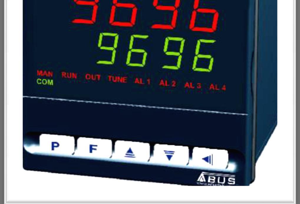
8 S.No. Parameters Description 1 A1-A4 Show active alarms. 2 COM Flashes when communication messages are sent by the controller. 3 TUNE Lights during the execution of PID automatic tuning. 4 MAN Lights when the controller is in manual. 5 RUN 6 OUT 7 P F Lights when the controller is active, with control and alarm outputs enabled. For relay or pulse control output, reflects the actual state of the output. If an analog output is assigned for control, lights continuously. Program Key: This key is used to access different displays with the programmable parameters of the device. Back Key: This key is used to go back to the previous parameter displayed in the menu cycle. UP / MAX Key: This key is used to increase parameter value, as well as to display maximum values stored in memory. DOWN / MIN Key: This key is used to decrease parameter value, as well as to display minimum values stored in memory. This special function key is used for pre-programmed functions as explained in the table below. 12 Display Shows the Process Variable (PV) and the programming prompts. 13 Display Shows the Set-Point Variable (SV) and the programming prompts. Pre-Programmed Functions S.NO. CYCLE ACCESS 1 Operation Free access parameters * 2 Tuning 3 R&S Program 4 Alarms Reserved access parameters ** 5 Input Configuration 6 I/Os 7 Calibration * These parameters can be viewed but not changed if the cycle is protected. ** Requires a key combination to access the cycle. ABUS TECHNOLOGIES INC. 8
9 7. CONFIGURATION 7.1 Programming the Indicator Operation Cycle PARAMETER PV Indication (Red) SV Indication (Green) avto PV Indication (Red) MV Indication (Green) Pr n rvn PROMPT PARAMETER DESCRIPTION PV AND SV INDICATION: The status display shows the present value of PV (Process Variable). The parameter display shows SV (Set Variable). The status display shows whenever PV exceeds the maximum range or there is no signal at the input. In case of hardware error the status display will show Ern, where n is the error code. CONTROL MODE: YES indicates automatic control mode (closed loop, PID or ON/OFF). NO indicates manual control mode (open loop). Bumpless transfer from auto to manual mode is available. If in doubt program YES. MANIPULATED VARIABLE VALUE (MV): The upper display shows PV value and the lower display shows the percentage of MV applied to the control output. When in manual control the MV value can be manually changed. When in auto mode the MV value can only be viewed. To distinguish the MV display from the SV display, the MV is shown flashing intermittently. RAMP AND SOAK PROGRAM SELECTION: Selects the ramp and soak program to be executed (7 programs possible). CONTROL ENABLE: YES means that the control output and alarms are enabled and NO means they are disabled Auto Tuning Cycle PARAMETER atvn Pb xyst PROMPT PARAMETER DESCRIPTION AUTO-TUNE: YES enables the auto tuning of the PID parameters and NO disables it. PROPORTIONAL BAND: Percentage of maximum input span. Select zero for ON/OFF control. CONTROL HYSTERESIS (in engineering units): This parameter is only shown for ON/OFF control (Pb=0). ir INTEGRAL RATE: Integral time constant in repetitions per minute (Reset). dt (t DERIVATIVE TIME: Derivative time constant, in seconds. CYCLE TIME: PWM period in seconds. Can only be viewed if proportional band is other than zero. bias Offset for MV (manual reset). Range: -100% to +100%. Default value: 0. ovll ovxl sfst OUTPUT LOW LIMIT: minimum percentage value for MV (Manipulated Variable) when in automatic control and PID. Default value: 0.0% OUTPUT HIGH LIMIT: Maximum percentage value for MV when in automatic control and PID. Default value: 100.0% SOFT START: Time in seconds during which the controller limits the MV value progressively from 0 to 100%. It is enabled at power up or when the control output is activated. If in doubt set zero. ABUS TECHNOLOGIES INC. 9
10 Sp.a1 ALARM 1 PRESET: Tripping point for alarm 1. Sp.a2 ALARM 2 PRESET: Tripping point for alarm 2. Sp.a3 ALARM 3 PRESET: Tripping point for alarm 3. Sp.a4 ALARM 4 PRESET: Tripping point for alarm Ramp and Soak Profile Programming Cycle PARAMETER tbas Pr n ptol Psp0 Psp7 Pt1 Pt7 Pe1 Pe7 lp tbas Pr n ptol Psp0 Psp7 Pt1 Pt7 Pe1 Pe7 lp PROMPT PARAMETER DESCRIPTION TIME BASE: Selects the time base for the ramp and soak. Valid for all profile programs. 0 - PT1 to PT7 values are in seconds; 1 - PT1 to PT7 values are in minutes; PROGRAM TO BE VIEWED: Selects the ramp and soak profile program to be edited/viewed in the following cycle prompts (7 programs available). RAMP AND SOAK TOLERANCE: maximum deviation between PV and SV. Whenever this deviation is exceeded the time counter is halted until deviation lowers to within the tolerance. Set zero to disable this function. RAMP AND SOAK SET POINTS (0 to 7): Set of 8 SV values which define the ramp and soak profile segments. See also PT1 to 7 and PE1 to 7 below. RAMP AND SOAK SEGMENTS TIME (1 to 7): Set of 7 time intervals for the 7 segments of the ramp and soak program. Up to 9999 seconds or minutes, according to tbas parameter. RAMP AND SOAK EVENT (1 to 7): Set of 7 values that define which alarms must be activated during a ramp and soak program segment. Alarm function depends on rs setting (Table ALARM FUNCTIONS). LINK TO PROGRAM: Number of the next profile program to be linked to follow the current profile. Profiles can be linked to make larger programs of up to 49 segments. TIME BASE: Selects the time base for the ramp and soak. Valid for all profile programs. 0 - PT1 to PT7 values are in seconds; 1 - PT1 to PT7 values are in minutes; PROGRAM TO BE VIEWED: Selects the ramp and soak profile program to be edited/viewed in the following cycle prompts (7 programs available). RAMP AND SOAK TOLERANCE: maximum deviation between PV and SV. Whenever this deviation is exceeded the time counter is halted until deviation lowers to within the tolerance. Set zero to disable this function. RAMP AND SOAK SET POINTS (0 to 7): Set of 8 SV values which define the ramp and soak profile segments. See also PT1 to 7 and PE1 to 7 below. RAMP AND SOAK SEGMENTS TIME (1 to 7): Set of 7 time intervals for the 7 segments of the ramp and soak program. Up to 9999 seconds or minutes, according to tbas parameter. RAMP AND SOAK EVENT (1 to 7): Set of 7 values that define which alarms must be activated during a ramp and soak program segment. Alarm function depends on rs setting (Table ALARM FUNCTIONS). LINK TO PROGRAM: Number of the next profile program to be linked to follow the current profile. Profiles can be linked to make larger programs of up to 49 segments. ABUS TECHNOLOGIES INC. 10
11 7.1.4 Alarm Cycle PARAMETER PROMPT PARAMETER DESCRIPTION Fva1 Fva2 Fva3 Fva4 ALARM 1 FUNCTION: Select options from Table ALARM FUNCTIONS. ALARM 2 FUNCTION: Select options from Table ALARM FUNCTIONS. ALARM 3 FUNCTION: Select options from Table ALARM FUNCTIONS. ALARM 4 FUNCTION: Select options from Table ALARM FUNCTIONS. bla1 bla2 bla3 bla4 xya1 ALARM BLOCK 1 TO 4: This function blocks the alarm at power-up when the unit is first energized. YES enables and NO inhibits this blocking function. When enabled the alarm will not be active at power-up waiting for PV (Process Variable) to reach a non-alarm situation. From this point on the alarm will be free to actuate should a new alarm situation occur. ALARM 1 HYSTERESIS: Defines the differential range between the PV value at which the alarm is turned on and the value at which it is turned off (in engineering units). xya2 ALARM 2 HYSTERESIS: Same as above. xya3 ALARM 3 HYSTERESIS: Same as above. xya4 ALARM 4 HYSTERESIS: Same as above. A1t1 A1t2 A2t1 A2t2 ALARM 1 TIME 1: Defines the time (6500 sec. max.) during which the alarm 1 output will be ON when alarm 1 is active. Program zero to disable this function. ALARM 1 TIME 2: Defines the OFF state time for the alarm 1 output, after being ON during the time selected on ALARM 1 TIME 1. Program zero to disable this function. ALARM 2 TIME 1: Defines the time (6500 sec. max.) during which the alarm 1 output will be ON when alarm 1 is active. Program zero to disable this function ALARM 2 TIME 2: Defines the time during which the alarm 2 output will be, after being ON during the time selected on ALARM 2 TIME 1. Program zero to disable this function. Table 4 shows the advanced features that can be achieved with these time functions. ABUS TECHNOLOGIES INC. 11
12 7.1.5 Configuration Cycle PARAMETER PROMPT PARAMETER DESCRIPTION type INPUT TYPE: Selects the input signal type to be connected to the process variable input. Refer to Table 1. This is the first parameter to be set. dppo DECIMAL POINT POSITION: For input types 16, 17, 18 or 19 only. Selects the decimal point position to be viewed in both PV and SV. vn I t TEMPERATURE INDICATION IN ºC OR ºF: Selects the display indication to be in ºC or ºF. Only available if input type is other than 16, 17, 18 or 19. offs SENSOR OFFSET: Offset value to be added to the PV to compensate sensor error. Default value: zero. spll SET POINT LOW LIMIT: - Linear inputs: Sets the lower range for SV and PV indication. - T/C and Pt100 inputs: sets the lower range for SV. spxl SET POINT HIGH LIMIT: - Linear inputs: Sets the upper range for SV and PV indication. - T/C and Pt100 inputs: sets the upper range for SV. rsll REMOTE SET POINT LOW LIMIT: Selects the lower range for indication of the Remote Setpoint. rsxl REMOTE SET POINT HIGH LIMIT: Selects the upper range for indication of the Remote Setpoint. bavd DIGITAL COMMUNICATON BAUD RATE SELECTION: 0: 1200bps; 1: 2400bps; 2: 4800bps; 3: 9600bps; 4: 19200bps. addr SLAVE ADDRESS SELECTION: Identifies a slave in the network. The possible address numbers are from 1 to 247. ABUS TECHNOLOGIES INC. 12
13 7.1.6 I/O Cycle PARAMETER I o 1 I o 2 I o 3 I o 4 I o 5 I o 6 f.fvnc PROMPT PARAMETER DESCRIPTION I/O 1 FUNCTION: Selects the I/O function to be used at I/O 1 (relay 1). Options 0 to 5 are possible for this output. Refer to Table 7.3 I/O channel functions for functions. I/O 2 FUNCTION: Selects the I/O function to be used at I/O 2 (relay 2). Options 0 to 5 are possible for this output. Refer to Table 7.3 I/O channel functions for functions. I/O 3 FUNCTION: Selects the I/O function to be used at I/O 3 (relay 3). Options 0 to 5 are possible for this output. Refer to Table 7.3 I/O channel functions for functions. I/O 4 FUNCTION: Selects the I/O function to be used at I/O 4 (relay 4). Options 0 to 5 are possible for this output. Refer to Table 7.3 I/O channel functions for functions. I/O 5 FUNCTION: Selects the I/O function to be used at I/O 5 (Analog Output). Functions 0 to 15 are available (See Table 7.3 I/O channel functions). This option is normally used for main control output or PV analog retransmission. I/O 6 FUNCTION: Selects the I/O function to be used at I/O 6 (Digital Input). Options 0, 6, 7, 8, 9 and 10 are possible for this input. Refer to Table 7.3 I/O channel functions for functions. F KEY FUNCTION: Selects the I/O function assigned to the front panel F key. Available functions are: 0 - Key not used; 6 - Manual/Automatic control selection; 7 - Start/Stop the controller (RUN function); 8 - Select remote setpoint; 9 - Execute/Hold ramp and soak profile; 10- Enable/Disable ramp and soak profile 1; Calibration Cycle All input and output types are factory calibrated. This cycle should only be accessed by experienced personnel. If in doubt do not press the or keys in this cycle. PARAMETER Inl( Inx( ovll Ovx( PROMPT PARAMETER DESCRIPTION INPUT LOW CALIBRATION: Sets the Process Variable low calibration (offset). Several keystrokes at or might be necessary to increment one digit. INPUT HIGH CALIBRATION: Sets the Process Variable span calibration (gain). OUTPUT LOW CALIBRATION: Sets the analog current output low calibration (offset). OUTPUT HIGH CALIBRATION: Sets the analog current output span calibration (gain). (j l COLD JUNCTION OFFSET CALIBRATION: Sets the cold junction offset calibration. Rsl( Rsx( REMOTE SET POINT LOW CALIBRATION: Sets the Remote Set Point low calibration (offset). Several keystrokes at or might be necessary to increment one digit. REMOTE SET POINT HIGH CALIBRATION: Sets the Remote Set Point span calibration (gain). ABUS TECHNOLOGIES INC. 13
14 7.2 Input Type Selection Select the input type (in parameter type ) from Table below. TYPE CODE CHARACTERISTICS J 0 Range: -50 to 760 C (-58 to 1400 ºF) K 1 Range: -90 to 1370 C (-130 to 2498 ºF) T 2 Range: -100 to 400 C (-148 to 752 ºF) N 3 Range: -90 to 1300 C (-130 to 2372 ºF) R 4 Range: 0 to 1760 C (32 to 3200 ºF) S 5 Range: 0 to 1760 C (32 to 3200 ºF) Pt100 6 Range: to C ( to ºF) Pt100 7 Range: -200 to 530 C (-328 to 986 ºF) 4-20 ma 8 J Linearization Programmable range: -110 to 760 C 4-20 ma 9 K Linearization Programmable range: -150 to 1370 C 4-20 ma 10 T Linearization Programmable range: -160 to 400 C 4-20 ma 11 N Linearization Programmable range: -90 to 1370 C 4-20 ma 12 R Linearization. Programmable range: 0 to 1760 C 4-20 ma 13 S Linearization Programmable Range: 0 to 1760 C 4-20 ma 14 Pt100 Linearization Prog. Range: to C 4-20 ma 15 Pt100 Linearization Prog. Range: -200 to 530 C 0-50 mv 16 Linear. Programmable indication to ma 17 Linear. Programmable indication to to 5Vdc 18 Linear. Programmable indication to ma 19 Square Root Extraction 7.3 Output and Digital Inputs Configuration The controller input/output channels can assume multiple functions, depending on configuration: control output, alarm output, digital output, digital input, and PV or SV analog retransmission. These channels are identified as I/O1, I/O2, I/O3, I/O4, I/O5 and I/O 6. The basic controller model comes loaded with: I/O1 and I/O2 I/O3 and I/O4 I/O5 I/O6 - Relay output SPDT; - Relay output SPST; - Analog output (0-20 or 4-20 ma), pulse, digital I/O; - Digital Input The function code of each I/O can be selected among the options on Table 2. Only valid function codes are displayed for each I/O (for example, I/O1, which is a relay, can be configured with ABUS TECHNOLOGIES INC. 14
15 functions 0 to 5 only; on the other hand, I/05 can perform all 16 functions). The description for the functions follows: CODE 0: No function - The I/O channel programmed with code 0 will not be used by the controller. It is available to be used by serial communication as digital output. CODES 1 to 4: Alarm output - Available for all I/O channels. The selected channel can be used as output to Alarms 1 to 4. CODE 5: PWM control output - Available for all I/O channels. CODE 6: Digital input - Available for I/O5 and I/O6 channels and key F. Closed: Opened: Manual control Automatic control I/O channel functions CODE I/O TYPE I/O FUNCTION 0 Digital Output Digital Output to be set by the serial comm. 1 Digital Output Alarm 1 Output 2 Digital Output Alarm 2 Output 3 Digital Output Alarm 3 Output 4 Digital Output Alarm 4 Output 5 Digital Output PWM Control Output 6 Digital Input Automatic/Manual mode change 7 Digital Input Run/Stop mode change 8 Digital Input Select Remote Set Point Input 9 Digital Input Executes/Holds selected ramp and soak profile 10 Digital Input Enable/Disable R&S profile 1 selection 11 Analog Output 0 ~ 20mA Analog control output 12 Analog Output 4 ~ 20mA Analog control output 13 Analog Output 0 ~ 20mA PV retransmission 14 Analog Output 4 ~ 20mA PV retransmission 15 Analog Output 0 ~ 20mA SP retransmission 16 Analog Output 4 ~ 20mA SP retransmission ABUS TECHNOLOGIES INC. 15
16 CODE 7: Digital input - Available for I/O5, I/O6 and key Yes / No). F. Start/Stop input ( rvn : Closed: Outputs Enabled Opened: Outputs Disabled CODE 8: Digital input - Available for I/O5, I/O6 and key F. Closed: Remote SP (4-20mA in remote SP input) Opened: Main SP (internal programmed SV) CODE 9: Digital input - Available for I/O5, I/O6 and key F. Closed: Enables R&S Program Opened: Holds R&S Program (the program resumes when the contact is closed again) CODE 10: Digital input - Available for I/O5, I/O6 and key F. Selects R&S program 1. Used to alternate between the main Set-point and a second Set-point defined by the R&S program 1. Closed: Selects Program 1 Opened: Uses Main Set-Point CODE 11: CODE 12: CODES 13 to 16: Analog control output - I/O5 only ma control output. Analog control output - I/O5 only ma control output. Analog retransmission -I/O5 only. Configures I/O5 to output a 0-20 ma or 4-20 ma analog signal proportional to PV or SP. 7.4 Alarm Configuration The controller has 4 alarms, with the front panel indicators. The alarms can the configured to operate in any of the nine functions listed on Table below ALARM TIMER FUNCTIONS Alarms 1 and 2 can be programmed to have timer functions. The 3 modes of operation are: * Pulse * Delayed actuation * Oscillator The desired function can be achieved programming the parameters A1t1, A1t2, A2t1 and A2t2.The LEDs associated to the alarms will light when the alarm condition is recognized, not following the actual state of the output, which may be temporarily OFF because of the temporization. ABUS TECHNOLOGIES INC. 16
17 7.4.2 ALARM FUNCTIONS TYPE PROMPT ACTION Disabled off No active alarm. This output can be used as a digital output to be set by the serial communication. Sensor Break (input Error) ierr Alarm will be ON if PV sensor breaks, input signal is out of range or Pt100 is shorted. Event Alarm (ramp and Soak) rs Can be activated at a specific segment of ramp and soak program. Heater break detection resistance fail rfail Detects a heater broken condition PV Low Alarm lo SPAn High Alarm ki PV SPAn PV LOW Differential difl Positive span SV + SPAn SV PV Negative span SV SV + SPAn PV HIGH Differential difk Positive span SV SV + SPAn Negative span SV + SPAn SV PV PV Differential dif Positive span SV - SPAn SV SV + SPAn PV Negative span SV - SPAn SV SV + SPAn Where SPAn means SPA1, SPA2, SPA2 and SPA4. ABUS TECHNOLOGIES INC. 17
18 Advanced Timer Alarm (for alarms 1 or 2): ALARM FUNCTION T1 T2 ACTION Normal 0 0 Delayed 0 1 s to 6500 s Pulse 1 s to 6500 s 0 Oscillator 1 s to 6500 s 1 s to 6500 s Alarm Output Alarm Output Alarm Output Alarm Event T2 Alarm Event T1 Alarm Event Alarm Output T1 T2 T1 Alarm Event ALARM INITIAL BLOCKING The initial blocking option inhibits the alarm from being recognized if an alarm condition is present when the controller is first energized. The alarm will actuate only after the occurrence of a nonalarm condition followed by a new occurrence for the alarm. The initial blocking is disabled for the sensor break alarm function SQUARE ROOT EXTRACTION Available when input type 19 is selected. The indicator displays the square root of the current signal input applied to terminals REMOTE SET-POINT The remote Set-point (SP) is enabled by an external digital signal in either I/O5 or I/O6, when programmed with code 8 (Select remote SP input) ANALOGUE RETRANSMISSION OF PV AND SP The analog output, when not used for control purposes, is available for retransmitting the SV and SP values in 0-20 or 4-20mA. This analog output is electrically isolated from other inputs and outputs. The analog output signal is scalable, with the output range determined by the values programmed in the parameters SPLL and SPkL. To obtain a voltage output, connect a resistor shunt to the current output terminals SOFT START Defines the time interval for the output to reach its maximum value (100%). The soft start value is programmed in SfSt. See also parameters ovll and ovkl. ABUS TECHNOLOGIES INC. 18
19 7.4.8 FUNCTION KEY AND DIGITAL INPUT (I/O6) FUNCTIONS Both the F key and the I/O6 digital input can be programmed to execute functions 7, 8, 9 and 10 shown in Table. The key function is configured in parameter ffvn. The digital input function is configured in parameter IO6. The digital input can also be configured for function 6: Auto/Manual mode change. 7.5 Program Security Each menu cycle can be locked (protected) by pressing and simultaneously for 3 seconds. Press and for 3 seconds to unlock. A short blink of the display confirms the lock/unlock change. This will alternately lock or unlock the and keys to avoid tampering. For further protection, the unlock operation through the keypad may be disabled by changing the position of an internal strap inside the controller: When PROT is OFF, the user is allowed to lock and unlock the cycles using the keypad as explained above. If PROT is ON, the cycles lock/unlock operation is disable. 7.6 Auto Tune During auto tune the process is controlled in ON/OFF mode at the programmed Set-Point Value (SV). Depending on the process characteristics large oscillations above and below SV may occur and auto tuning may take several minutes to be concluded. The recommended procedure is as follows: Disable the control output at the rvn prompt by selecting NO. Select auto mode operation at the Avto prompt by selecting YES. Disable the ramp and soak function (select NO) and program a new SV value other than the present PV (close to the desired set point). Enable auto tuning at the Atvn prompt by selecting YES. Enable the control output at the rvn prompt by selecting YES. During the auto tune procedure the soft-start function will not operate and large oscillations will be induced around the setpoint. Make sure the process can accept these oscillations and fast control output changes. If auto tuning results are not satisfactory refer to the table below for manual fine tuning procedure. Suggestions for manual tuning of PID parameters PARAMETER RESPONSE SOLUTION Proportional Band Integral Rate Derivative Time Slow Response Large Oscillation Slow Response Large Oscillation Slow Response or Instability Large Oscillation Decrease Increase Increase Decrease Decrease Increase ABUS TECHNOLOGIES INC. 19
 for the time intervals that follow the last segment to be executed.")


20 7.7 Ramp and Soak Profile Program Seven ramp and soak profiles with up to 7 segments each can be programmed. Longer profiles of up to 49 segments can be created by linking 2 or more profiles. Example of a complete ramp and soak profile To execute a profile with fewer segments just program 0 (zero) for the time intervals that follow the last segment to be executed. Example of a profile with fewer segments (T4 is set 0) The program tolerance Ptol defines the maximum deviation between PV and SV for the execution of the profile. If this deviation is exceeded, the program will be interrupted until the deviation falls to within the tolerance band. Programming 0 (zero) at this prompt disables the tolerance and the profile execution will not to be halted even if PV does not follow SV (time priority as opposed to SV priority). Example of two linked programs The ramp and soak event function is used to activate alarms at any segment of program 1. This applies only to program 1. To enable this event function the alarms to be activated must be selected for rs function and are programmed at the PE 0 to PE 7 prompts. The number to be programmed at the prompt defines the alarms to be activated. To configure and execute a ramp and soak program: Program the tolerance value, SV, time and event. If any event alarm is required program the ramp and soak event function. Set the control mode to automatic. Select ramp and soak program to be executed at prompt Prn (0 to 4) Start control at the run prompt rvn by selecting YES. ABUS TECHNOLOGIES INC. 20
21 Before executing the program the controller waits for PV to reach the first set point SP0 if PtoL is different than zero. Should any power failure occur, when the controller resumes at the beginning of the segment that it was previously executing. Event codes for ramp and soak CODE ALARM 1 ALARM 2 ALARM 3 ALARM X 2 X 3 X X 4 X 5 X X 6 X X 7 X X X 8 X 9 X X 10 X X 11 X X X 12 X X 13 X X X 14 X X X 15 X X X X 7.8 Serial Communication An optional RS485 serial communication interface is available which allows up to 247 controllers in a network to communicate to a master device RS485 Compatible signals with RS485 standard; Two-wire connection from master to up to 247 slave controllers in a multi-drop bus; Maximum communication distance: 1000 meters; General Characteristics Optically isolated serial interface Programmable Baud rate: 1200, 2400, 4800, 9600 or bps. Data Bits: 8 Parity: None Stop Bits: 1 ABUS TECHNOLOGIES INC. 21
22 8. SAFETY PRECAUTIONS 1. The unit should be powered for 15 minutes before use. 2. Use in ambient temperature of 0-60 C. 3. Avoid vibrations, shock, excessive dust, corrosive chemical materials or gaseous environment. 4. Input wire should not be too long. If measured signal have to be far away from the unit, please use 2-core shielded cable. 5. Use this instrument in the scope of its specifications, otherwise fire or malfunctions may result. 6. Contact of the instrument, with organic solvents or oils should be avoided. 7. Do not turn on the power supply until all of the wiring is completed. Otherwise electrical shock, fire or malfunction may result. 8. Do not disassemble, repair or modify the instrument. 9. All connections should be tightened properly. 10. Power supply should be constant, should not be fluctuating. 9. WARRANTY ABUS provides the original purchaser of this instrument a one (1) year warranty against defects in material and workmanship under the following terms: The one year warranty begins on the day of shipment as stated on the sales bill. During the warranty period all costs of material and labor will be free of charge provided that the instrument does not show any evidence of misuse. For maintenance, return the instrument with a copy of the sales bill to our factory. All transportation and insurance costs should be covered by the owner of the equipment. Should any sign of electrical or mechanical shock, abuse, bad handling or misuse be evident the warranty voids and maintenance costs will be charged. ABUS TECHNOLOGIES INC. info@abustek.com ABUS TECHNOLOGIES INC. 22
K Tc k Range: -150 a 1370 ºC (-238 a 2498 ºF) T N R S B E
 T N R S B E") UNIVERSAL PROCESS CONTROLLER INSTRUCTIONS MANUAL V3.0x SAFETY ALERTS The symbols below are used on the equipment and throughout this document to draw the user s attention to important operational and safety
UNIVERSAL PROCESS CONTROLLER INSTRUCTIONS MANUAL V3.0x SAFETY ALERTS The symbols below are used on the equipment and throughout this document to draw the user s attention to important operational and safety
UDC 1000 and UDC 1500 MICRO-PRO SERIES UNIVERSAL DIGITAL CONTROLLERS
 UDC 1000 and UDC 1500 MICRO-PRO SERIES UNIVERSAL DIGITAL CONTROLLERS EN0I-6041 12/99 PRODUCT SPECIFICATION SHEET OVERVIEW The UDC 1000 and UDC 1500 are microprocessor-based 1/16 DIN and 1/8 DIN controllers
Controller N960. UNIVERSAL CONTROLLER INSTRUCTIONS MANUAL V4.0x SAFETY SUMMARY RESOURCES INSTALLATION
 Controller N960 UNIVERSAL CTROLLER INSTRUCTIS MANUAL V4.0x SAFETY SUMMARY The symbols below are used on the equipment and throughout this document to draw the user s attention to important operational
1/32-DIN TEMPERATURE CONTROLLER INSTALLATION, WIRING AND OPERATION MANUAL FORM 3882
 1/32-DIN TEMPERATURE CONTROLLER INSTALLATION, WIRING AND OPERATION MANUAL FORM 3882 This manual is intended for use in support of installation, commissioning and configuration of the 1/32-DIN Temperature
Tempco Instruction Manual
 Tempco Instruction Manual 1/16 DIN Solid State Temperature Controller Relay Output Solid State Output For Heating Model Numbers: TEC-901, TEC-902, TEC-905 Temperature controls in this series are designed
UDC1200 and UDC1700 MICRO-PRO SERIES UNIVERSAL DIGITAL CONTROLLERS
 UDC1200 and UDC1700 MICRO-PRO SERIES UNIVERSAL DIGITAL CONTROLLERS 51-52-03-35 11/06 PRODUCT SPECIFICATION SHEET OVERVIEW The UDC1200 & UDC1700 are microprocessor-based 1/16 DIN and 1/8 DIN controllers
SX90 Process Controller
 Local regulations may restrict the use of this product to below the conditions quoted. In the interests of development and improvement of the product, we reserve the right to change the specification without
Digital Indicating Controllers. JC Series. High performance controllers...at the lowest prices anywhere! Toll Free
 Digital Indicating Controllers JC Series High performance controllers...at the lowest prices anywhere! www.mod-tronic.com Toll Free 1-800 794-5883 Standard Features Structure Units available in standard
- SELF-TUNING PID ALGORITHM - INTUITIVE COLOR DISPLAY WITH TEXT MESSAGING - UNIVERSAL PROCESS AND TC/RTD INPUTS - MULTI- FUNCTION RAMP- DWELL/PROCESS
 ELK. ETK COMPACT BASIC CONTROL - SELF-TUNING PID ALGORITHM - INTUITIVE COLOR DISPLAY WITH TEXT MESSAGING - UNIVERSAL PROCESS AND TC/RTD INPUTS - MULTI- FUNCTION RAMP- DWELL/PROCESS TIMER - SOFT START OUTPUT
/8 DIN Universal Process Indicator
 Data Sheet SS/_ High visibility LED display the clearest view of your process status.% measurement accuracy precise indication of process measurement Analog and relay outputs as standard alarm and retransmission
ABB Instrumentation. Specification DataFile COMMANDER 100. the-easy-to use 1. /8 DIN controller with extensive application capabilities
 COMMANDER Universal Process Controller Specification DataFile PID controller with one shot autotune single loop, heat/cool and ramp/soak as standard Quick code, front face or PC configuration easy commissioning
Universal power supply
 Honeywell UDC1200 and UDC1700 MICRO-PRO SERIES UNIVERSAL DIGITAL CONTROLLERS 51-52-03-35 5/03 PRODUCT SPECIFICATION SHEET OVERVIEW The UDC1200 & UDC1700 are microprocessor-based 1/16 DIN and 1/8 DIN controllers,
Operating Guide MODBUS (RTU) Communications Option IM/L150 MOD_2. Level Indicator L150 and L160
 Communications Option IM/L150 MOD_2. Level Indicator L150 and L160") Operating Guide MODBUS (RTU) Communications Option IM/L150 MOD_2 Level Indicator L150 and L160 Electrical Safety This equipment complies with the requirements of CEI/IEC 61010-1:2001-2 "Safety requirements
Operating Guide MODBUS (RTU) Communications Option IM/L150 MOD_2 Level Indicator L150 and L160 Electrical Safety This equipment complies with the requirements of CEI/IEC 61010-1:2001-2 "Safety requirements
User Guide IM/C250 MOD_3. Modbus (RTU) Communications Option C250 and V250
 Communications Option C250 and V250") User Guide IM/C250 MOD_3 Modbus (RTU) Communications Option C250 and V250 Electrical Safety This instrument complies with the requirements of CEI/IEC 61010-1:2001-2 "Safety requirements for electrical
User Guide IM/C250 MOD_3 Modbus (RTU) Communications Option C250 and V250 Electrical Safety This instrument complies with the requirements of CEI/IEC 61010-1:2001-2 "Safety requirements for electrical
/8 DIN Motorized Valve Controller
 Data Sheet SS/_5 Boundless motorized valve controller no need for slidewire feedback; improves reliability Two sealed 5A control relays suitable for direct connection to the valve, reducing installation
MRC 7000 Proven Recording Reliability that Became the Industry Standard!
 Data Sheet Recorder//Profiler DESCRIPTION The MRC7000 Recorder/ is a microprocessor based circular chart instrument capable of measuring, displaying, recording and controlling up to two process variables
JUMO Quantum PID100/PID200/PID300
 Data sheet 702020 Page 1/12 JUMO Quantum PID100/PID200/PID300 Universal PID Controller Series Brief description The Quantum series is available in the three DIN formats 48 mm x 48 mm, 48 mm x 96 mm, and
PXR Series Advanced Self-Tuning Temperature and Process Controllers
 PXR Series Advanced Self-Tuning Temperature and Process Controllers Key Features PID Description with fuzzy control of self-tuning 16 Ramp/soak segments Large LED display Auto-tune Timer function Heater
Trident and Trident X2 Digital Process and Temperature Panel Meter
 Sign In New User ISO 9001:2008 Certified Quality System Home Products Online Tools Videos Downloads About Us Store Contact Policies Trident and Trident X2 Digital Process and Temperature Panel Meter Products
Temperature/Process Controllers Manual
 3200 SERIES Temperature/Process Controllers Manual The innovative range of 3200 controllers offer precision control of temperature and other process variables together with a host of advanced features
Wall-/Pipe Mounted Universal Process Indicator
 Data Sheet SS/_8 Wall-/Pipe Mounted Universal Process Indicator High visibility LED display the clearest view of your process status 0.1% measurement accuracy precise indication of process measurement
12-36 VDC/12-24 VAC Power Option 4-Digit Display, 0.56 (14.2 mm) or 1.20 (30.5 mm)
 or 1.20 (30.5 mm)") 4-20 ma & Relay Output Features 4-20 ma, ± 10 V, TC & RTD Inputs 12-36 VDC/12-24 VAC Power Option 4-Digit Display, 0.56 (14.2 mm) or 1.20 (30.5 mm) 24 VDC @ 200 ma Transmitter Power Supply Options Type
4-20 ma & Relay Output Features 4-20 ma, ± 10 V, TC & RTD Inputs 12-36 VDC/12-24 VAC Power Option 4-Digit Display, 0.56 (14.2 mm) or 1.20 (30.5 mm) 24 VDC @ 200 ma Transmitter Power Supply Options Type
SINGLE-CHANNEL PROCESS INDICATOR series 8001
 SINGLE-CHANNEL PROCESS INDICATOR series 8001 Analog Inputs - all inputs available in one unit - Pt100 RTD type DIN 43 760 or GOST 6651-78 (range from 0 to +600 C) - TC type: J - range from 0 to +600 C
UDC1200 & UDC1700 Universal Digital Controllers Series Micro-Pro Specifications
 UDC1200 & UDC1700 Universal Digital Controllers Series Micro-Pro Specifications 51-52-03-35 June 2011 Overview The UDC1200 & UDC1700 are microprocessor-based 1/16 DIN and 1/8 DIN controllers, which combine
User Guide Supplement Modbus TM Serial Data Communications Option IM/C100 MOD_6. /8 DIN Process Indicators and Controllers C100, C150, C160 and V100
 User Guide Supplement Modbus TM Serial Data Communications Option IM/C100 MOD_6 1 /8 DIN Process Indicators and Controllers C100, C150, C160 and V100 Electrical Safety This equipment complies with the
Athena Series RMC Hot Runner Controller Configuration and Operation Manual
 Athena Series RMC Hot Runner Controller Configuration and Operation Manual Athena and CompuStep are registered trademarks, and Multi-Comm and SafeChange are trademarks of Athena Controls, Inc. MODBUS is
Omni. User Manual. Economic Self-Tune PID Temperature Controller. Omni 96. Omni 72 72X72. Omni ~ 265 V AC SUPPLY
 Omni Economic Self-Tune PID Temperature Controller Omni 7 Omni 4 6 5 4 3 1 7X7 7 1 11 5 ~ 65 V AC SUPPLY Omni 6 CONTENTS 1. PANEL MOUNTING & ELECTRICAL CONNECTIONS 1. FRONT PANEL : LAYOUT AND OPERATION
C160 Wall-/Pipe Mounted Universal Process Indicator
 Data sheet DS/ EN Rev. I Wall-/Pipe Mounted Universal Process Indicator reliable process indicator, wherever it s needed High visibility LED display the clearest view of your process status 0.1% measurement
H Series PLC. ! : Indicates Compulsion. EH-150 Analog input module EH-AXH8M Instruction manual. Safety precautions DANGER CAUTION COMPULSION
 H Series PLC EH-150 Analog input module EH-AXH8M Instruction manual Thank you for purchasing a Hitachi Programmable Logic Controller. To operate it safely, please read this instruction manual and all the
2 Table of Contents 1. TABLE OF CONTENTS. 1. Table of Contents Introduction Wiring Diagram Terminals Review...
 TPR-6 Temperature Protection Relay Instruction Manual Ver. June 1 st 2010 2 Table of Contents 1. TABLE OF CONTENTS 1. Table of Contents... 2 2. Introduction... 3 3. Wiring Diagram... 5 4. Terminals Review...
MLC 9000 Bus Compatible PID
 MLC 9000 Bus Compatible PID Modbus, DeviceNet, Profibus Compatable The MLC 9000 is a unique, stand alone PID control solution to use instead of discrete DIN controllers. Reduce Wiring Costs Clean up the
MODCELL 2050R Single Loop Controllers
 Isolated universal process and remote set-point input Four internal set-points No jumpers required to define instrument parameters Ratio/bias on process and remote set-point Totalizer Ramp/soak profile
Operating Manual. Dynisco /8 DIN Indicator Concise Product Manual
 Dynisco 1490 1/8 DIN Indicator Concise Product Manual 59476-9 Operating Manual -1- CAUTION: Installation should be only performed by technically competent personnel. Local Regulations regarding electrical
OLS VT10 SERIES STANDARD DUAL DISPLAY PID AUTOTUNE RAMP-TO-SETPOINT ULC, UL, CE (4810) AUTO / MANUAL 15 SECURITY OPTIONS UNIVERSAL INPUT
 AUTO / MANUAL 15 SECURITY OPTIONS UNIVERSAL INPUT") TEMPERATURE TURE CONTROLS OLS VT10 SERIES pg.1 STANDARD DUAL DISPLAY PID AUTOTUNE RAMP-TO-SETPOINT ULC, UL, CE (4810) AUTO / MANUAL 15 SECURITY OPTIONS UNIVERSAL INPUT OPTIONS DUAL OUTPUT ALARMS - 15 TYPES
TEMPERATURE TURE CONTROLS OLS VT10 SERIES pg.1 STANDARD DUAL DISPLAY PID AUTOTUNE RAMP-TO-SETPOINT ULC, UL, CE (4810) AUTO / MANUAL 15 SECURITY OPTIONS UNIVERSAL INPUT OPTIONS DUAL OUTPUT ALARMS - 15 TYPES
Omni + User Manual. Dual Setpoint Temperature Controller with Programmable Input & TIMER. Omni 96+ Omni 72+ Omni 48+ TMR TMR TMR
 Omni + Dual Setpoint Temperature Controller with Programmable Input & TIMER Omni 72+ Omni 48+ TMR TMR Omni 96+ TMR CONTENTS 1. PANEL MOUNTING & ELECTRICAL CONNECTIONS 1 2. FRONT PANEL : LAYOUT AND OPERATION
DUAL-LINE TEMPERATURE METER
 DUAL-LINE TEMPERATURE METER PROPLUS YPP7000 J, K, T, E, R, S, B, N, C Thermocouples 100 or 1000 Ω Platinum, 10 Ω Copper, 120 Ω Nickel RTDs 1 or 0.1 Resolution Averages up to 10 RTD Sensors Automatic Cold
Zenex-ultra Ultra Precision (0.01 C) Self-Tune PID Temperature Controller with Programmable Timer
 Self-Tune PID Temperature Controller with Programmable Timer") Ultra Precision (0.01 C) Self-Tune PID Temperature Controller with Programmable Timer CONTENTS 1. FRONT PANEL LAYOUT 1. BASIC OPERATION 3. PAGES & PARAMETERS 3 4. INSTALLATION PARAMETERS 5 5. CONFIGURATION
Ultra Precision (0.01 C) Self-Tune PID Temperature Controller with Programmable Timer CONTENTS 1. FRONT PANEL LAYOUT 1. BASIC OPERATION 3. PAGES & PARAMETERS 3 4. INSTALLATION PARAMETERS 5 5. CONFIGURATION
ESM H 77x35 DIN Size Heating Controller Digital, ON / OFF Temperature Controller
 Internal Buzzer ESM- 3711-H 77x35 DIN Size Heating Controller ESM-3711-H 77 x 35 DIN Size Digital, ON / OFF Temperature Controller - 3 Digits display - PTC Input or, J type Thermocouple Input or, K type
ControlMaster CM10, CM30 and CM50 Universal process controllers, 1 /8, 1 /4 and 1 /2 DIN
 User Guide Basic Functionality IM/CM/B EN Rev. Q ControlMaster CM10, CM30 and CM50 The Company We are an established world force in the design and manufacture of instrumentation for industrial process
ProVU 4 Advanced Temperature & Process Controller
 ProVU 4 Advanced Temperature & Process Controller 1/4 DIN Format Graphical / text LCD Display (red/green) Profiling option Datalogging option (data, alarms & events) 5 language (English, French, German,
HITACHI. EH-150 series PLC EH-RTD8 Resistance Temperature Detective input module Instruction manual. Safety precautions
 HITACHI EH-150 series PLC Resistance Temperature Detective input module Instruction manual Thank you for purchasing a Hitachi Programmable Logic Controller. To operate it safely, please read this instruction
DIGITAL INDICATING CONTROLLER
 DB1000 SERIES DIGITAL INDICATING CONTROLLER The DB1000 series is a 96 96mm digital indicating controller with the indicating accuracy of ±0.1% and the control cycle of approximately 0.1 seconds. Various
FY Series Digital PID Controller Operation Manual FY400 FY700 FY800 FY900 FY600
 FY Series Digital PID Controller Operation Manual FY101 90X90mm FY100 15X110mm FY400 FY00 FY800 FY900 FY600 48x48mm 2X2mm 48X96mm 96X96mm 96X48mm (DIN 1/) (DIN 3/) (DIN 1/8) (DIN 1/4) (DIN 1/8) February,
PD765 TRIDENT. Trident Series Process & Temperature Meters.
 PD765 Trident Series Process & Temperature Meters TRIDENT PROCESS & Temp 4-20 ma, ± 10 V, TC & RTD Inputs 4-Digit Display, 0.56 (14.2 mm) or 1.20 (30.5 mm) Type 4X, NEMA 4X, IP65 Front 1/8 DIN Shallow
The IQ240 panel mount load cell indicator is a precision digital indicator for load cell and strain gauge applications.
 IQ240 Panel Mount Load Cell Indicator Data sheet English 1.01 Introduction The IQ240 panel mount load cell indicator is a precision digital indicator for load cell and strain gauge applications. The high
D1000M SERIES FOR MODBUS SENSOR TO COMPUTER INTERFACE MODULES
 D1000M SERIES FOR MODBUS SENSOR TO COMPUTER INTERFACE MODULES D1000 FEATURES Complete sensor to RS-232/RS-485 interface. 500V rms analog input isolation. 15 bit measurement resolution. Continuous self-calibration;
TECHNICAL DATA SHEET. ProVU 4 Advanced Temperature Controller. Features. Description
 ProVU 4 Advanced Temperature Controller ¼ DIN Format Graphical / text LCD Display (red/green) Profiling option Datalogging option (data, alarms & events) 5 language (English, French, German, Italian, Spanish)
2. Terminal arrangement TEMPERATURE CONTROLLER KT2 COMMUNICATION INSTRUCTION MANUAL. (Fig. 2-1)
") COMMUNICATION INSTRUCTION MANUAL TEMPERATURE CONTROLLER No.KTC3E2 2006.08 To prevent accidents arising from the misuse of this controller, please ensure the operator receives this manual. For this product
COMMUNICATION INSTRUCTION MANUAL TEMPERATURE CONTROLLER No.KTC3E2 2006.08 To prevent accidents arising from the misuse of this controller, please ensure the operator receives this manual. For this product
Masibus Automation And Instrumentation Pvt. Ltd.
 Operator s Manual DIGITAL CONTROLLER 5006H Masibus Automation And Instrumentation Pvt. Ltd. B/30, GIDC Electronics Estate, Sector-25, Gandhinagar-382044, Gujarat, India Ph: 91 79 23287275-79 Fax: 91 79
The IQ300 wall mount load cell indicator is a precision digital indicator for load cell and strain gauge applications.
 IQ300 Wall Mount Load Cell Indicator Data sheet English 1.01 Introduction The IQ300 wall mount load cell indicator is a precision digital indicator for load cell and strain gauge applications. The high
PLC-24V10AL(-PT/-TH) Quick Start Manual (Rev.1.10)
 Quick Start Manual (Rev.1.10)") TEC (Peltier) Controller PLC-24V10AL(-PT/-TH) Quick Start Manual (Rev.1.10) Thank you for purchasing the TEC (Peltier) Controller PLC-24V10AL. Read these operating instructions carefully to ensure effective
TEC (Peltier) Controller PLC-24V10AL(-PT/-TH) Quick Start Manual (Rev.1.10) Thank you for purchasing the TEC (Peltier) Controller PLC-24V10AL. Read these operating instructions carefully to ensure effective
Temperature, Process &
 Temperature, Process & 150 For Temp. Units 1/32 DIN meter 195 with 2 control outputs User Friendly, Simple to Configure High Quality i/32 i/16 i/8 Extended 5-Year Warranty Powerful Features Free Software,
RXTH DUAL ROOM SENSOR / SWITCH
 DUAL ROOM SENSOR / SWITCH FOR TEMPERATURE AND RELATIVE HUMIDITY Mounting and operating instructions Table of contents SAFETY AND PRECAUTIONS 3 PRODUCT DESCRIPTION 4 ARTICLE CODES 4 INTENDED AREA OF USE
Universal Process Controller
 Data Sheet SS/_9 Universal Process ontroller Single output, Heat/ool or Motorized Valve control one controller for every PID control application 9 program, segment Ramp/Soak comprehensive set point profiling
H3 Series. Nanmac Corporation. Dual-Line 6-Digit Temperature Meter.
 H3 Series Dual-Line 6-Digit Temperature Meter Temperature J, K, T, E, R, S, B, N, C Thermocouples 100 or 1000 Ω Platinum, 10 Ω Copper, 120 Ω Nickel RTDs 1 or 0.1 Resolution Averages up to 10 RTD Sensors
TRACKER 240 SERIES. Load Cell and Weighing Indicators. A Precision Measurement Instrument with Outstanding Features
 TRACKER 240 SERIES Load Cell and Weighing Indicators A Precision Measurement Instrument with Outstanding Features TRACKER 240 SERIES INDICATORS Ratiometric Measurement Tare and Auto Transducer Excitation
100mm Process Indicator Recorder
 Data Sheet SS/_3 100mm Process Indicator Recorder One or two pen continuous line 100mm recorder universal input for thermocouple, RTD, mv, ma and V Clear, 5-digit LED display high visibility, wide viewing
TABLE OF CONTENTS INTRODUCTION. 3. Analog Input Analog Output Digital Input Digital Output OPERATIONAL DESCRIPITON.. 7 PROGRAMMING AND INITIAL SETUP.
 DIVERSIFIED HEAT TRANSFER SERIES 700 STEAM GENERATOR CONTROLLER INSTRUCTION MANUAL VISIT OUR WEBSITE AT SIGMACONTROLS.COM SERIES 700 DHT STEAM GENERATOR MANUAL 042514 2 TABLE OF CONTENTS INTRODUCTION.
PRODUCT SPECIFICATION. PC Board Relays. Series.
 PRODUCT SPECIFICATION PC Board Relays 26 Series www.wernerelektrik.com Technical Data... Specifications...2 Model Number Structure - Relays...3 Model Number Selection...4 Dimensions... 5-6 Accessories...7
Ultra Slim Relays 24
 Ultra Slim Relays 24 Technical Data... 1 Specifications.2 Model Number Structure - Relays...3 Model Number Selection...4 Accessories...5 Safety Precautions...6 Ultra Slim Relays WERNER`s embody the latest
Model HU-224/225. Technical Information TI.224/ Humidity Transduce r FOR ADDITIONAL INFORMATION SEE HU-224/225 DATA SHEET
 Model /225 FOR ADDITIONAL INFORMATION SEE /225 DATA SHEET SPECIFICATIONS Accuracy*: ± 2% / ± 3% RH Range: 0-100% RH Hysteresis: ± 1% Supply Voltage:12-40 VDC 12-35 VAC (VDC output units only) Supply Current:
DIGITAL PANEL THERMOMETER
 Love Controls DIGITAL PANEL THERMOMETER LCI108-1x LCI108J-1x INSTRUCTION MANUAL EDITION: January 2001 INTRODUCTION TO THE LOVE CONTROLS LCI108 SERIES This manual does not constitute a formal agreement.
Instructions for TPC Power Through Control Console
 Visionary Solutions for Industry Since 1972 ISO 9001 Certified Temperature Controllers & Sensors Heating Elements Process Heating Systems Instructions for TPC Power Through Control Console SPECIFICATIONS
The CAL range of temperature controllers
 The CAL range of temperature controllers CAL Temperature Controllers Auto-tuning P.I.D. Controllers with RS232/485 Communication, Charting and Logging Software The CAL range of temperature controllers
General Specifications. P2-08THM Analog Input
 General Specifications Operating Temperature Storage Temperature Humidity Environmental Air Vibration Shock Field to Logic Side Isolation Heat Dissipation Enclosure Type Agency Approvals Module Keying
5450 NW 33rd Ave, Suite 104 Fort Lauderdale, FL Fruitland Ave Los Angeles, CA SST7000 SST7100. Speed Switch / Transmitter
 5450 NW 33rd Ave, Suite 104 Fort Lauderdale, FL 33309 3211 Fruitland Ave Los Angeles, CA 90058 SST7000 SST7100 Speed Switch / Transmitter Installation and Operation Manual Rev. C P/N145F-13112 PCO 00009270
ControlMaster CM10, CM30 and CM50 Universal process controllers, 1 /8, 1 /4 and 1 /2 DIN
 User Guide Basic Functionality IM/CM/B-EN ControlMaster CM10, CM30 and CM50 The Company We are an established world force in the design and manufacture of instrumentation for industrial process control,
DXTH DUCT SENSOR / SWITCH FOR TEMPERATURE AND HUMIDITY. Mounting and operating instructions
 DUAL DUCT SENSOR / SWITCH FOR TEMPERATURE AND HUMIDITY Mounting and operating instructions Table of contents SAFETY AND PRECAUTIONS 3 PRODUCT DESCRIPTION 4 ARTICLE CODES 4 INTENDED AREA OF USE 4 TECHNICAL
LAUREL. Laureate RTD Temperature Panel Meter / Controller ELECTRONICS, INC. Features. Description. Specifications
 LAUREL ELECTRONICS, INC. Laureate RTD Temperature Panel Meter / Controller Features Factory calibrated for 100Ω platinum, 10Ω copper & 120Ω nickel RTDs 2, 3 or 4-wire connection with lead resistance compensation
PD765 TRIDENT. Trident Series Process & Temperature Meters.
 PD765 Trident Series Process & Temperature Meters TRIDENT PROCESS & Temp 4-20 ma, ± 10 V, TC & RTD Inputs 4-Digit Display, 0.56" (14.2 mm) or 1.20" (30.5 mm) Linear or Square Root with Low-Flow Cutoff
deltadue series DIN rail mounting modules for control and data acquisition
 DIN EN ISO 9001 : 2000 QA-Nr.: 041002000292 deltadue series DIN rail mounting modules for control and data acquisition S E R I E S Process controllers Temperature controllers Transmitters with alarms I/O
Genset Controller Unit Model EMS - GC10. Installation Manual Section
 Genset Controller Unit Model EMS - GC10 Installation Manual 00-02-0794 Section 75 2013-01-28 In order to consistently bring you the highest quality, full featured products, we reserve the right to change
LAUREL ELECTRONICS, INC.
 LAUREL ELECTRONICS, INC. Laureate RTD Temperature Panel Meter / Controller Features Factory calibrated for 100Ω platinum, 10Ω copper & 120Ω nickel RTDs 2, 3 or 4-wire connection with lead resistance compensation
D7000 SERIES MODBUS TCP/IP ETHERNET INTERFACE MODULES
 11/17 D7000 SERIES MODBUS TCP/IP ETHERNET INTERFACE MODULES D7000 FEATURES Complete data acquisition systems. Analog and Digital I/O models available. RJ-45 Ethernet 10/100MB interface. Modbus TCP/IP Ethernet
Operation Manual MODEL 2TX. 2-wire Isolated ph/orp Transmitter
 Operation Manual MODEL 2TX 2-wire Isolated ph/orp Transmitter 0 2TX CONTENTS INITIAL INSPECTION.....2 INTRODUCTION......2 ASSEMBLY...3 PREPARATION....4 CONNECTING THE ELECTRODE...4 CONNECTING THE TEMPERATURE
PD Helios Dual-Line 6-Digit Temperature Meter. Actual Size Digit
 PD2-7000 Helios Dual-Line 6-Digit Temperature Meter Actual Size Digit Temperature Large 1.80" Digits Dual-Line 6-Digit Display Readable from up to 100 Feet (30 Meters) Away Superluminous Sunlight Readable
MAXIMA + Series ROTARY LEVEL CONTROL
 Price $5.00 MAXIMA + Series ROTARY LEVEL CONTROL OPERATING INSTRUCTIONS PLEASE READ CAREFULLY Division of Garner Industries 7201 North 98th Street Lincoln, NE 68507-9741 (402) 434-9102 925-0268 Rev. A
PD7000. PROVU Dual-Line 6-Digit Temperature Meter SERIES.
 PD7000 PROVU Dual-Line 6-Digit Temperature Meter PR VU SERIES Temperature J, K, T, E, R, S, B, N, C Thermocouples 00 or 000 Ω Platinum, 0 Ω Copper, 0 Ω Nickel RTDs or 0. Resolution Averages up to 0 RTD
Instructions for Switched TPC Series Control Consoles
 Visionary Solutions for Industry Since 1972 ISO 9001 Certified Temperature Controllers & Sensors Heating Elements Process Heating Systems Instructions for Switched TPC Series Control Consoles SPECIFICATIONS
5450 NW 33rd Ave, Suite 104 Fort Lauderdale, FL Fruitland Ave Los Angeles, CA UM Channel Monitor.
 5450 NW 33rd Ave, Suite 104 Fort Lauderdale, FL 33309 3211 Fruitland Ave Los Angeles, CA 90058 UM-600 6-Channel Monitor Version 2 Installation and Operation Manual Rev. G P/N145F-12990 PCO 00007462 (c)
Iso DIN. User Manual. 1 channel Earth Fault Monitoring
 Page 1 of 5 2017 03 20 User Manual Iso DIN Iso DIN User Manual 1 channel Earth Fault Monitoring Megacon AB Ranhammarsvägen 20 S 168 67 Bromma Sweden Tel: 08 402 42 50 sales@megacon.se www.megacon.se eee
Installation, Operation and Maintenance Manual
 Document 481200 VGD-100 Vari-Green Drive Installation, Operation and Maintenance Manual Please read and save these instructions for future reference. Read carefully before attempting to assemble, install,
PRODUCT FAMILY: SOLO Controllers Number: AN-LC-009
 THIS INFORMATION PROVIDED BY AUTOMATIONDIRECT.COM TECHNICAL SUPPORT IS SUPPLIED "AS IS", WITHOUT ANY GUARANTEE OF ANY KIND. These documents are provided by our technical support department to assist others.
RXTP ROOM TEMPERATURE
 ROOM TEMPERATURE CONTROLLER WITH PI CONTROL Mounting and operating instructions Table of contents SAFETY AND PRECAUTIONS 3 PRODUCT DESCRIPTION 4 ARTICLE CODES 4 INTENDED AREA OF USE 4 TECHNICAL DATA 4
LLR-MOD Modbus Light Level and Occupancy Sensor
 Product sheet SN1.418 Type LLR-MOD LLR-MOD Modbus Light Level and Occupancy Sensor The LLR-MOD sensors are designed to measure Light Level (LUX) in the room spaces and have built-in RS485 Modbus communication
DCP250. Controller Programmer Presentation
 DCP250 Controller Programmer Presentation DCP250 Overview Controller and Programmer with Graphic Display 1/4 DIN (96x96mm) size One or two control loops Programmer (255 segments shared in up to 64 programs)
Operation Manual TX10 1/8 DIN Microcomputer Based ph/orp Controller
 Operation Manual TX10 1/8 DIN Microcomputer Based /ORP Controller 11751 Markon Drive Garden Grove, CA. 92841 U.S.A. pg. 1 CONTENTS GENERAL INTRODUCTION.....3 INITIAL INSPECTION......3 USING THE Sensorex
Series Temperature Controller Instruction Sheet
 2016/12/20 Series Temperature Controller Instruction Sheet Precaution Warning! Please comply with safety precautions in the manual. Failure to do so may cause controller or peripheral products malfunction,
DIGITAL PANEL THERMOMETER
 Love Controls DIGITAL PANEL THERMOMETER LCI108-2x LCI108J-2x INSTRUCTIONS MANUAL EDITION: February 2001 INTRODUCTION TO THE LOVE CONTROLS LCI108 SERIES This manual does not constitute a formal agreement.
Operating instructions. Speed monitor D / / 2014
 Operating instructions Speed monitor D200 80005257 / 00 05 / 2014 Contents 1 Preliminary note...4 1.1 Symbols used...4 1.2 Warning signs used...4 2 Safety instructions...5 2.1 General...5 2.2 Target group...5
Conductive Level Controller
 Conductive Level Controller 61F-D21T-V1 Ideal for level control for industrial facilities and equipment. Outputs can be set to self-hold at ON or OFF using self-holding circuits. Sensitivity adjustment
MYRIAD QLC 4-CHANNEL MONITOR/CONTROLLER INSTRUCTION MANUAL
 MYRIAD QLC 4-CHANNEL MONITOR/CONTROLLER INSTRUCTION MANUAL VISIT OUR WEBSITE SIGMACONTROLS.COM MYR QLC MANUAL 013114 2 TABLE OF CONTENTS INTRODUCTION 3 Ordering Information Specifications Features WIRING
MU110-6U. Analog output module 6 channel. User guide
 MU110-6U Analog output module 6 channel User guide MU110-6U_2016.12_0221_EN All rights reserved Subject to technical changes and misprints akytec GmbH Vahrenwalder Str. 269 A 30179 Hannover Тел.: +49 (0)
Temperature I/O Module HE800MIX963 / HE-MIX963* * HE- denotes plastic case.
 MAN0353-05 10 NOV 2006 PAGE 1 Temperature I/O Module HE800 / HE-* * HE- denotes plastic case. This datasheet also covers products starting with IC300. 1 SPECIFICATIONS Relay Outputs Number of Channels
WSK INTELLIGENT TEMPERATURE AND HUMIDITY CONTROLLER USER MANUAL
 WSK INTELLIGENT TEMPERATURE AND HUMIDITY CONTROLLER USER MANUAL WSK INTELLIGENT TEMPERATURE AND HUMIDITY CONTROLLER USER MANUAL v 1.0 Thanks for choosing the Intelligent temperature and humidity controller
SmartBlock I/O Module HE579MIX577/977 Isolated 4/8 Analog Inputs 2/4 Analog Outputs
 MAN0969-02 PAGE 1 Mix577/977 Module ` SmartBlock I/O Module HE579MIX577/977 Isolated 4/8 Analog Inputs 2/4 Analog Outputs 1 SPECIFICATIONS Analog Inputs High Resolution Steady State Current 120mA @ 24v
INSTALLATION MANUAL. LC 200 Electronic Overload Guard. Software versione PW0501 R 0.3
 INSTALLATION MANUAL LC 200 Electronic Overload Guard Software versione PW0501 R 0.3 CONTENTS MAIN FEATURES LC 200 TECHNICAL FEATURES Page 2 SYMBOLS Page 3 WARNINGS Page 3 IDENTIFICATION DATA PLATE Page
TC Type Range Conformity Error. J -210 C to +760 C (-347 F to F) ±0.09 C (±0.16 F) K -244 C to C (-408 F to F) ±0.1 C (±0.
 ±0.09 C (±0.16 F) K -244 C to C (-408 F to F) ±0.1 C (±0.") LAUREL ELECTRONICS, INC. Laureate Thermocouple Panel Meter / Controller Features Factory calibrated for thermocouple types J, K, T, E, N, R, S Entire range of each thermocouple in one scale Highly accurate
LAUREL ELECTRONICS, INC. Laureate Thermocouple Panel Meter / Controller Features Factory calibrated for thermocouple types J, K, T, E, N, R, S Entire range of each thermocouple in one scale Highly accurate
Chapter. Modbus. In This Chapter...
 Modbus Communication Chapter 7 In This Chapter... Modbus Protocol....7 2 Registers....7 2 Connection with the DirectLOGIC PLC....7 8 Connection with the C-more and C-more Micro HMI panels....7 10 Modbus
Soft Starter Remote Operator. Section 1.0 Introduction 1.1 Important user information General Manual description...2.
 Section 1.0 Introduction 1.1 Important user information... 2 1.2 General... 2 1.3 Manual description...2 Contents Section 2.0 Specification 2.1 General technical data...3 2.2 Dimensions...3 Section 3.0