2005 Pioneer Home Audio Seminar VSX49TX
|
|
|
- Charlotte Horn
- 6 years ago
- Views:
Transcription

1 2005 Pioneer Home Audio Seminar VSX49TX Pioneer Electronic Service, Inc. 2005
2
3 Introduction Why the VSX49TX? The VSX49TX is not current product, however it tends to be the most difficult to repair! What will be covered? The receiver in general; more specifically Display & System Micro Amplifier and Protection circuit. Power Supply DSP circuitry Trouble Shooting Tips
4 This seminar manual will be specifically about troubleshooting techniques, no operation instructions, no theory!
5 What will you get out of this? You will learn the most successful troubleshooting methods designed to get the unit on and off your bench as quickly as possible. You will learn more accurate repair techniques and avoid having to replace costly boards on out-of-warranty units. Replacing expensive boards can sometimes mean the difference between getting the repair or having the customer walk!
6 Topics we will cover Minor disassembly DSP circuitry Amplifier & Protection circuits System Microprocessor Display Microprocessor Power Supply Additional resources

7 Disassembly Remove no more than you have to! Use caution when removing the back panel screws. They are different! You are using your ESD wrist strap aren t you? ESD precautions are a fact of life! Why do your work over and over again due to static damaged components!
8 To start 1. Place unit as pictured and remove top, bottom and side covers. 2. Prop up unit as pictured for easy access. 3. Remove all screws holding the DSP boards, as well as any attached connectors or wire ties.


9 Remove only the screws necessary as shown below. Why spend more time than you have to?

10 Use caution when removing screws. There are 3 different types!

11 Keep track of the screw types. Correct place for screw with integral flat and attached star washer.

12 With the screws removed, gently pull back on the back panel, while extracting the DSP and DSP3 assemblies.

13 DSP boards removed
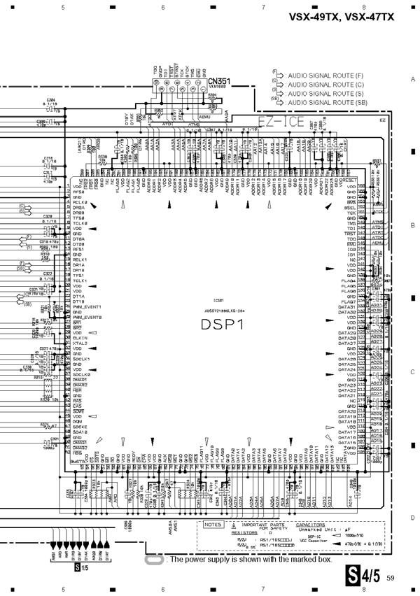
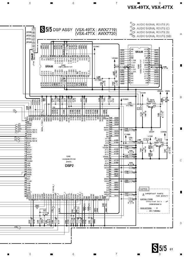
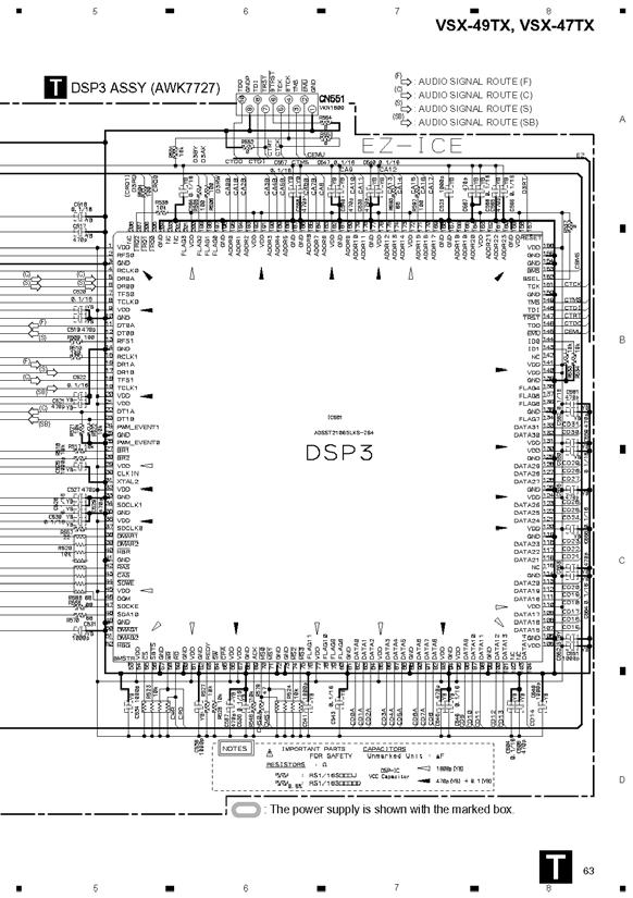
14 Digital Signal Processing The DSP circuit consists of 3 boards 1. AWK7719 DSP ASSY 2. AWK7727 DSP3 ASSY 3. AWK7725 DAC10 ASSY
15 DSP assemblies DAC10 ASSY #3 DSP3 ASSY #2 DSP ASSY #1
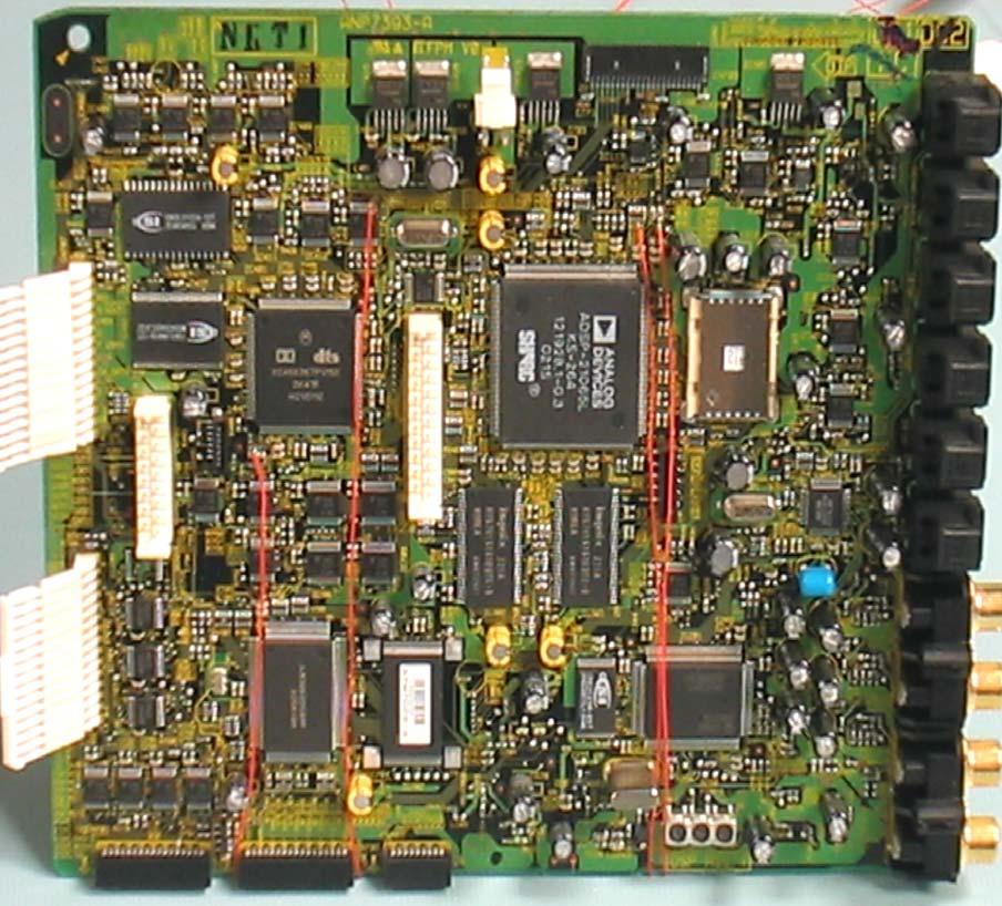
16 DSP ASSY
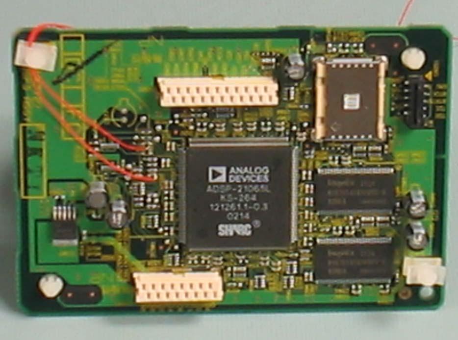
17 DSP3 ASSY

18 DAC10 ASSY
 Must use DVD with Surround information {Be sure to look at front panel display} For the purpose of this seminar, we will follow the")
19 Setup DVD Digital Input either Coaxial or Optical Speaker setup 5.1 or 5 channel(without Subwoofer) Must use DVD with Surround information {Be sure to look at front panel display} For the purpose of this seminar, we will follow the left surround channel only. Indicators must illuminate for all channels driven. No illumination, no audio!
, may vary by + or -.")
20 For your reference only Depending on the accuracy of your scope, this voltage, 5 volts (TTL level), may vary by + or -.5 volts.

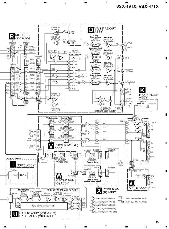
21 DSP Audio Block Diagram

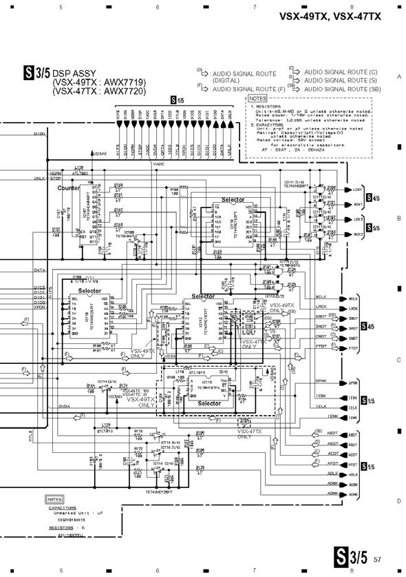
22 DSP Audio Circuit

23 DSP Audio Circuit continued

24 DSP Audio Circuit continued

25 DSP Audio Circuit continued

26 DSP Audio Circuit continued
27 DSP Audio Circuit continued
28 Test point DIR & DIT Pin 3 IC112 DIR & DIT Pin 3 In

29 Test point DIR&DIT IC101 Pin 3 More noise than signal IC101 Pin 3 DIR & DIT In
30 Test point DIR&DIT Pin 25 IC101 Pin 25 DIR&DIT Out

31 Test point DIR&DIT Pin 25 IC101 Pin 25 DIR&DIT Out
32 Test point Selector IC112 Pin 3 IC 112 Pin 3 Selector In

33 IC112 Pin 3 Selector In Test point IC112 Pin 3
34 Test point Selector IC112 Pin 4 IC112 Pin 4 Out

35 Test point Selector IC112 Pin 4 Test Point Pin 4 Out
36 IC301 DSP1 Pin 6 In Test point DSP1 IC301 Pin 6

37 Test point DSP1 IC301 Pin 6 Waveform very small. More noise than signal!
38 Test point DSP1 IC301 Pin 12 IC301 DSP1 Pin 12 Out

39 Test point DSP1 IC301 Pin 12
40 Test point DSP2 IC401 Pin 11 IC401 DSP2 Pin 11 In

41 Question How do I troubleshoot the DSP2 IC? It s located directly under the DSP3 ASSY. Answer.. Simply remove the DSP3 ASSY. There won t be any sound output from the unit, but you can scope the digital waveform none the less! DSP2 IC is under here.

42 Test point DSP2 IC401Pin 11 In
43 IC401 DSP2 Pin 5 Out DSP2 IC401 Pin 5 Out
44 DSP2 IC401 Pin 5 Out
45 DSP3 IC501 Pin 6 In IC501 DSP3 Pin 6 In

46 DSP3 IC501 Pin 6 In
47 DSP3 IC501 Pin 12 Out IC501 DSP3 Pin 12 Out

48 DSP3 IC501 Pin 12 Out
49 DAC10 CN6002 Pin 11 In DAC10 ASSY CN6002 Pin 11 In
50 DAC10 CN6004 Pin 10 Out DAC10 ASSY CN6004 Pin 10 Out

51 DAC10 CN6004 Pin 10 Out End of the line! Analog audio! Success!
52 Conclusion to DSP troubleshooting 1. Follow the digital signal into and out of DSP1, DSP2 and DSP3 ICs. Compare to waveforms seen in this presentation. 2. Look at the digital signal entering DAC10 ASSY. Look for analog signal to follow. 3. Loss of signal at any point requires back tracking to last good test point.
53 DSP Audio Flow Path Ideal path to follow(left Surround) JA107(DSP ASSY) IC101(DSP ASSY) IC112(DSP ASY) IC301(DSP1)(DSP ASSY) IC410(Selector)(DSP ASSY) IC401(DSP2)(DSP ASSY) CN402(DSP ASSY) CN501(DSP3 ASSY) IC501(DSP3)(DSP3 ASSY) CN501(DSP3ASSY) CN402(DSP ASSY) CN402(DSP ASSY) CN707(DSP ASSY) Continued
54 Continued DSP Path CN6002(DAC10) IC6061(DAC10) IC6303(DAC10) IC6305(DAC10) CN6004(DAC10) CN5813(MotherASSY) CN5818(Mother ASSY) CN5001(VR &Pre Out) IC5001(VR & Pre Out) IC5061(VR & Pre Out) CN5006(VR & Pre Out) CN4801(Power Amp) IC4401(Power Amp) JA4801(Power Amp) Speaker


55 DSP Socket Issues IC304 on DSP ASSY and IC504 on DSP3 ASSY. Cold solder connections on these sockets can cause loss of audio in DSP mode. For complete loss of audio, at times associated with these sockets, try resoldering socket to PCB first. At the same time, clean and coat pins of socket and IC with DeOxit, or similar compound. If this doesn t resolve the problem, remove the IC socket and solder the IC directly to the board.
56 DSP troubleshooting tips Complete loss of audio Step 1. Use Multi-Channel input jacks at rear. Step 2. Switch unit to Multi-Channel. Step 3. If audio returns, unit has a DSP ASSY problem. If still no audio, remove DSP ASSY board and repeat steps 1 and 2. If audio returns, probable cause DSP ASSY. Step 4. If unit still has no audio, probable cause is VR & PRE OUT ASSY and beyond. Step 5. To further isolate the problem, remove Main in/ Preout jumpers and insert audio directly into Main in, front channel. If still no audio, unit has amplifier problem. Don t forget to reinsert jumpers!
57 Easy tips for troubleshooting audio Loss of Analog audio Insert audio(signal Injector), or noise(put finger on Test Point to generate noise), to ensure continuation of signal past that point. Move forward or backward in the circuit as needed. Noise on Analog audio channel Use capacitor, or just short(if there is no DC voltage present) Test Point to ground at any point to silence the noise. From that point and beyond, the circuit is OK. Move forward or backwards in the circuit as needed. Please use caution and exercise good judgment!
58 Amplifier and Protection Circuit
59 Protection Circuit
60 Problem Unit shuts off Display reads AMP ERROR Probable cause Damaged amplifier components.
61 Can there be other causes? YES! How do I know if the amplifier is damaged for certain?

 denotes DC Offset and probable")
62 How to check for DC Offset CN5819 DC Detection, Pin 15. Should be low(0v + -.5V)in normal operation. A high(5v + -.5V) denotes DC Offset and probable Amplifier damage.
63 What if DC Offset is detected? How do I know which of the 7.1 channel(s) is bad?
64 Test points to narrow choices for DC Offset Please note: DC Offset at these Test points can only be measured when the Power Supply voltages are up to spec.

65 What if the voltage is within spec? Check these transistors for all channels. Possibly shorted!
66 None of those other parts bad? Last place to look!
67 Amplifier
68 Amplifier Failures 1. Voltage Amp Bad Voltage Amp IC. If after replacing damaged IC(s), the amplifier(s) still shows DC Offset, one or both of these resistor(s) may be open!
69 Amplifier Failures 1. Amplifier output Number 1 cause Always replace in pairs. Don t assume this is the only damage!

70 Amplifier Failures 2. Amplifier output If amplifier continues to have DC Offset after replacing output F.E.T.s, be sure to check these.1 Ohm resisters
71 System Microprocessor Basics
72 Standby Voltage On/Off RYCTRL= Relay Control Don t become confused! This output line controls the operation of the standby 5.6 V line, not the AC relays.

73 Energizing AC Relays If no DC Offset is present, Pins 58 and 60 will change state to control Port Expander IC. PIN 60 EXPOE2 Change of state enables Expander IC 1103 to allow data input. PIN 58 EXPDT2 Data output to Expander IC1103 to control AC1 and AC2 lines for AC relays.
74 Turn on signal for AC relays from Micro RAC1 & RAC2 To turn on AC Relays Tip Look for change of state Data and control lines
75 Mute Main and Multi-Room Pin 67 changes state to mute audio lines supplying MULTI-ROOM Outputs. Pin 66 changes state to mute all audio lines to MAIN amplifiers.
76 Display Microprocessor Basics
77 Turn on procedure Key Scan 1 line Key Scan in lines. Most important for Turn On, Key Scan 1. Look for low when pressing the Stand By button. This point, when statically measured, (when pushed) 14.9K Ohms to ground. IC3001
78 Communication between Micros Wake-Up output signal from IC3001, Pin 7, to input IC 5801, pin 20.
79 Volume up and down Volume up Look for change of state from high to low when turning volume up. Tip: Erratic voltage at Test point? Change Volume Encoder.
80 Volume down Look for change of state from high to low when turning volume down. Tip: Erratic voltage at Test point? Change Volume Encoder.
81 Changing inputs Look for change of state from high to low when turning the input knob to the left. Tip: Changing inputs by itself? 1. Look into bulletin SI-H04018-G.PDF 2. Change Input Encoder.
82 Changing inputs Look for change of state from high to low when turning the input knob to the right. Tip: Changing inputs by itself? 1. Look at bulletin SI-H04018-G.PDF 2. Change Input Encoder.
83 Things to keep in mind First and foremost, don t overlook the obvious! This is a very complex receiver. There are 16 fuses, A.K.A. IC Protectors, 11 regulator ICs and countless fusible resistors! There are published Tips related to nothing but blown fuses!
84 To aid in Troubleshooting First be sure the unit is not drawing more than 1.65 amps at 120 volts! Placing a short across C1002 will allow the unit to be run up slowly on a Variac.
 1.")
85 Normal Condition Unit at idle, no input, no load (Note: 2.5 amp scale) 1.65 amp + or 10%
86 Note to current draw Normal current draw after settling, 1.65 amps. Note: The unit will draw in excess of 7.5 amps as you run up the AC voltage. Look for the current to drop as soon as you stop increasing the voltage. If it doesn t, pull the plug! The unit is shorted!
87 Be sure to check all regulated supplies
88 Power supply voltages CN volts Digital volts Digital volts volts volts volts Tuner volts volts
89 Power supply voltages J Ground
90 Power supply voltages J volts 2. Ground volts volts 5. Ground volts
91 Power supply voltages Very important! Stand by 5.6 volts for the microprocessor
92 Please check on our Web Site for all Tips and Bulletins when repairing any product.
93 One brief note on ESD Located on our PioneerElectronics.com website under training 5S ESD Training The importance of ESD safe practice and preparation is vital to our mutual success. It s no longer business as usual in the Digital Environment. Precautions must be taken or damage WILL occur
94 Additional resources for ESD information 1. ESDsystems.com 2. Desco.com
95 We sincerely hope you will benefit from this information. Thank you
96
Installation instructions DC Protection and Delay unit, Version 1.2 The package should contain: A piece of normal gauge yellow wire for the AC connect
 Installation instructions DC Protection and Delay unit, Version 1.2 How does the unit work? Delay: Basically a capacitor is charged via a resistor, when the voltage of the capacitor reach a certain level,
Universal Keying Adapter 3+
 Universal Keying Adapter 3+ The Universal Keying Adapter Version 3+ kit will allow you to key nearly any transmitter or transceiver with a straight key, electronic keyer, computer serial or parallel port
TC-7533 Bushmaster Instruction Manual
 TC-7533 Bushmaster Instruction Manual Front Panel Stereo Audio Digital-to-Analogue Converter Overview The TC-7533 Bushmaster is a reference-quality digital-to-analogue audio converter featuring the latest
9 th Generation Plasma Display. Technical Information
 9 th Generation Plasma Display Technical Information 1 The technicians have express their needs and we listened. This presentation has been developed especially for the technicians involved in the repair
AirTest Model CN9000 Series Sensor Controller
 AirTest Model CN9000 Series Sensor Controller AirTest Model CN9000 Series Sensor Controller THEORY OF OPERATION A basic CN9000 configuration consists of Input/Process/Display combination modules, a 3 relay
Axiom Manufacturing. Users Manual. for PROJECT DEVELOPMENT BOARD AXM xiom anufacturing
 Axiom Manufacturing Users Manual for PROJECT DEVELOPMENT BOARD AXM-0295 xiom anufacturing 1999 2813 Industrial Ln. Garland, TX 75041 (972) 926-9303 FAX (972) 926-6063 support@axman.com Rev 1.0 web: http://www.axman.com
Beresford Capella Headphone amplifier
 Beresford Capella Headphone Amplifier Owner s Reference manual REV 1.7 Introduction The Capella is a high end headphone amplifier designed for audiophile listening. It can accept audio signals from an
Installation Instructions
 Installation Instructions This document provides information on: important pre-installation considerations power supply requirements installing the module connecting the wiring using the indicators for
Sierra Radio Systems. HamStack. Project Board Reference Manual V1.0
 Sierra Radio Systems HamStack Project Board Reference Manual V1.0 Welcome HamStack Project Board Reference Manual Revision 1.0.3 2011 George Zafiropoulos, KJ6VU and John Best, KJ6K This guide provides
Schematic Diagram: R2,R3,R4,R7 are ¼ Watt; R5,R6 are 220 Ohm ½ Watt (or two 470 Ohm ¼ Watt in parallel)
") Nano DDS VFO Rev_2 Assembly Manual Farrukh Zia, K2ZIA, 2016_0130 Featured in ARRL QST March 2016 Issue Nano DDS VFO is a modification of the original VFO design in Arduino Projects for Amateur Radio by
Nano DDS VFO Rev_2 Assembly Manual Farrukh Zia, K2ZIA, 2016_0130 Featured in ARRL QST March 2016 Issue Nano DDS VFO is a modification of the original VFO design in Arduino Projects for Amateur Radio by
DSI-4. DMX Optically Isolated 1x4 Splitter. D Series. DSI_4 Users Manual r3.lwp copyright 2009, 2010, 2011 ELM V. T. Inc.
 DSI-4 DMX Optically Isolated 1x4 Splitter D Series 1 Table Of Contents IMPORTANT SAFEGUARDS... DSI-4 OVERVIEW... CONNECTION... PCB BLOCK DIAGRAM... SERVICING... TROUBLESHOOTING... SPECIFICATIONS... 2 3
Blue Point Engineering
 Blue Point Engineering Board - Pro Module (E) Instruction Pointing the Way to Solutions! Controller I Version 2.1 The Board Pro E Module provides the following features: Up to 4 minutes recording time
Technical Guide Plasma (GPH10DU Chassis) Troubleshooting Handbook
 Troubleshooting Handbook") Technical Guide Plasma (GPH10DU Chassis) Troubleshooting Handbook Model : TH-42PX75U TH-50PX75U TH-42PX77U TH-50PX77U Panasonic Services Company National Training Prepared by Panasonic Service and Technology
Technical Guide Plasma (GPH10DU Chassis) Troubleshooting Handbook Model : TH-42PX75U TH-50PX75U TH-42PX77U TH-50PX77U Panasonic Services Company National Training Prepared by Panasonic Service and Technology
TC-7530DC with BMI-10
 TC-7530DC with BMI-10 Bushmaster MKI Instruction Manual Stereo Audio Digital-to-Analogue Converter Front Panel Overview The TC-7530DC Bushmaster is a reference-quality digital-to-analogue audio converter
RC Tractor Guy Controller V2.1 Assembly Guide
 RC Tractor Guy Controller V. Assembly Guide Features 0 Push button inputs Dual axis thumb sticks with built-in push button Rotary encoders with built-in push button MCU Socket to suit Meduino Mega 560
PDP One Point Repair Guide ~ 42 Inch Practice Inch Practice
 PDP One Point Repair Guide 1. 40 ~ 42 Inch Practice 2. 60 Inch Practice P6 cause : bad connection between Y-Board # 1, 2 drive board Connector pin Rework should be done P4 Y-Driver Board Y-Board P 6 P
Twisted Nitro Stunt Racing New Cabinet Design with Sintra Marquee Supplement to Operation & Service Manual
 Twisted Nitro Stunt Racing New Cabinet Design with Sintra Marquee Supplement to Operation & Service Manual Document Part #: 040-0271-01 Rev. C Your cabinet has a new design with a Sintra Marquee, stand-alone
Button Code Kit. Assembly Instructions and User Guide. Single Button Code Entry System
 Button Code Kit Single Button Code Entry System Assembly Instructions and User Guide Rev 1.0 December 2009 www.alan-parekh.com Copyright 2009 Alan Electronic Projects Inc. 1. Introduction... 4 1.1 Concept
Code Practice Oscillator (CPO)
") Code Practice Oscillator (CPO) Overview Many thanks for your purchase of this code practice oscillator or CPO, this guide is intended to allow you to quickly get operational. The CPO comprises an approx.
Code Practice Oscillator (CPO) Overview Many thanks for your purchase of this code practice oscillator or CPO, this guide is intended to allow you to quickly get operational. The CPO comprises an approx.
November 2000 Mixed-Signal Products SLOU086
 User s Guide November 2000 Mixed-Signal Products SLOU086 IMPORTANT NOTICE Texas Instruments and its subsidiaries (TI) reserve the right to make changes to their products or to discontinue any product or
Cumbria Designs T-1. C-1 Controller. User Manual
 Cumbria Designs T-1 C-1 Controller User Manual CONTENTS 1 INTRODUCTION 2 2 CIRCUIT DESCRIPTION 2 3 ASSEMBLY 3 4 CONNECTIONS AND CONFIGURATION 4 5 TESTING 6 Appendix A C-1 Circuit Diagram and PCB Component
SP-100. Service Manual Aug. 02
 SP-100 Service 2004. Aug. 02 1. Caution for maintenance and Service. Please take care below points when you do Service and Maintenance. (1) Service and Maintenance should be done under safety condition.
Installation/assembly manual for DCC/Power shield
 Installation/assembly manual for DCC/Power shield The DCC circuit consists of the following components: R1/R6 R2/R3 R4/R5 D1 C2 2 kω resistor ½ Watt (colour code Red/Black/Black/Brown/Brown) 10 kω resistor
Preface About this User's Guide... iv What you will learn from this user's guide... iv Conventions in this user's guide... iv
 Table of Contents Preface About this User's Guide... iv What you will learn from this user's guide... iv Conventions in this user's guide... iv Chapter 1 Introducing the PCI-PDISO8... 1-1 Overview: PCI-PDISO8
AUDIO AMPLIFIER PROJECT
 Intro to Electronics 110 - Audio Amplifier Project AUDIO AMPLIFIER PROJECT In this project, you will learn how to master a device by studying all the parts and building it with a partner. Our test subject:
NEDSP1068-PCBA NEDSP1068-PCBA-MIC DSP
 bhi Ltd PO Box 318, Burgess Hill, RH15 9NR England. Tel: +44 (0)1444 870333 Fax: +44 (0)845 217 9936 info@bhi-ltd.com, www.bhi-ltd.com NEDSP1068-PCBA NEDSP1068-PCBA-MIC DSP Noise Cancelling Modules With
What s in the Box. Table of Contents
 Table of Contents 1. What s in the Box 2. Warning 2. Overview 3. Quick Start Guide 4. Rear Panel 5. Front Panel 5. DC trigger 5. Logo trim tool 6. Troubleshooting Guide 7. Warranty and Service 8. Contact
PN59D7000FFXZA Fast Track Troubleshooting Manual, Rev. 1/11/12
 , Rev. 1/11/12 Y Buffer Spkr Y Main Buffer E HELP: 1-888-751-4086 (Tech Support) 1-866-894-0637 (FE) GSPN http://gspn3.samsungcsportal.com PLUS ONE http://my.plus1solutions.net/clientportals/samsung HOT
Plasma Panel Replacement Guide DU-42PX12X
 Plasma Panel Replacement Guide DU-42PX12X Panel Replacement: At this point, the panel has been determined to be defective and replacement is necessary. Upon receiving the replacement panel, it must be
KAA Watt x 2 Class-D Audio Amplifier Kit
 KAA10021 50 Watt x 2 Class-D Audio Amplifier Kit This amplifier kit uses Texas Instruments TPA3116D2 stereo audio amplifier IC for driving speakers up to 50 watts @ 4 ohm per channel in stereo mode and
Cursa 3 manual.qxd 10/12/ :23 Page 1. Contents
 Cursa 3 manual.qxd 10/12/2002 15:23 Page 1 Contents Introduction...1 Design Innovation...2 Installation...3 DC Protection...4 Pre-Amp Outputs...5 Input Connection...6-8 In Use...9-10 Input Selection...11
********SERVICE MANUAL******** MODELS:
 ********SERVICE MANUAL******** MODELS: 75211-10 Variable Speed Drive, 5000 RPM, 115 V 75211-15 Variable Speed Drive, 5000 RPM, 230 V, CE Mark 75211-60 Variable Speed Drive w/pump, 9000 RPM, 115 V 75211-62
Mercury Manual No. IM-M1000 Rev G
 Mercury 1000 Analog Output Encoder System Installation Manual and Reference Guide Manual No. IM-M1000 Rev G Introduction MicroE Systems was founded to advance encoder technology to a level never before
ARRL ETP Solder Hour Clock Kit Construction Manual
 ARRL ETP Solder 101 24-Hour Clock Kit Construction Manual Do a complete parts check cross checking the individual parts against the parts list. Pay particular attention to the color code for the resistors:
css Custom Silicon Solutions, Inc.
 css Custom Silicon Solutions, Inc. CSS555 EZ Programmer Operating Manual Version 1.0, May 2012 Contents Operating Instructions & Features.... 2 Programmer PCB Diagram.... 3 555 Timer Configuration Settings
CHAPTER 5. Voltage Regulator
 CHAPTER 5 Voltage Regulator In your robot, the energy is derived from batteries. Specifically, there are two sets of batteries wired up to act as voltage sources; a 9V battery, and two 1.5V batteries in
Resolver to Digital Expansion Board
 Resolver to Digital Expansion Board Catalog No. EXB009A01 Installation and Operating Manual 6/98 MN1313 Table of Contents Section 1 General Information............................. 1-1 Introduction....................................
Design Modular Planning
 Phys253 - Lecture 7, Part II Circuit Components & Layout Design Modular Planning Design by assembling simple circuit modules, such as filters or amplifiers Modules may be separated by buffers, where required
Elecraft K3 KPA3 Power Connector Replacement Revision B, June 30, 2017 Copyright 2017, Elecraft, Inc. All Rights Reserved
 Introduction Elecraft K3 KPA3 Power Connector Replacement Revision B, June 30, 2017 Copyright 2017, Elecraft, Inc. All Rights Reserved The connectors furnishing high current to the KPA3 module have failed
User's Guide. Model W 3-in-1 Switching DC Power Supply
 User's Guide Model 382260 80W 3-in-1 Switching DC Power Supply Introduction Congratulations on your purchase of the Extech 80W 3-in-1 Switching DC Power Supply. The Model 382260 has three output ranges
High Power (15W + 15W) Stereo Amplifier
 Stereo Amplifier") High Power (15W + 15W) Stereo Amplifier Build Instructions Issue 1.0 Build Instructions Before you put any components in the board or pick up the soldering iron, just take a look at the Printed Circuit
High Power (15W + 15W) Stereo Amplifier Build Instructions Issue 1.0 Build Instructions Before you put any components in the board or pick up the soldering iron, just take a look at the Printed Circuit
PRe6. Multi-Channel Analog Pre-Amplifier
 User's Guide and Warranty Information PRe6 Multi-Channel Analog Pre-Amplifier Bel Canto Design, LTD. 212 Third Avenue North Minneapolis, MN 55401 Phone: (612) 317.4550 Fax: (612) 359.9358 www.belcantodesign.com
Octagon Systems Corporation, the Octagon logo, the Micro PC log and Micro PC are trademarks of Octagon Systems Corporation.
 5974 PC 104 Card COPYRIGHT Copyright 1993 Octagon Systems Corporation. All rights reserved. However, any part of this document may be reproduced provided that Octagon Systems Corporation is cited as the
Installation Instructions
 Installation Instructions This document provides information on: important pre-installation considerations power supply requirements initial handling procedures installing the module using the indicators
VS. 4 Game Selector INSTALL GUIDE
 VS. 4 Game Selector INSTALL GUIDE Each DK Selector includes the following items: 1. VS. 4 Game Selector PWB 2. 4 power cables 12, 14, 16 & 18 3. Ribbon daisy chain cable 4. Mounting feet and screws Some
MP3 audio amplifier. Build Instructions. Issue 2.0
 MP3 audio amplifier Build Instructions Issue 2.0 Build Instructions Before you put any components in the board or pick up the soldering iron, just take a look at the Printed Circuit Board (PCB). The components
VG-305A AC Traffic Light Controller Kit
 Galak Electronics Electronic kits and components Website: GalakElectronics.com Email: sales@galakelectronics.com Phone: (302) 832-1978 VG-305A AC Traffic Light Controller Kit Thank you for your purchase
Zero Volt Monitor Installation, Operation and Maintenance
 TECHNICAL BULLETIN TB-6515 Zero Volt Monitor Installation, Operation and Maintenance Made in the United States of America strap properly, the monitor measures the loop resistance consisting of one wire
2001 Mixed-Signal Products SLOU091A
 User s Guide 2001 Mixed-Signal Products SLOU091A Preface How to Use This Manual This document contains the following chapters: Chapter 1 Introduction Chapter 2 Operation Related Documentation From Texas
DK 4 Game Selector INSTALL GUIDE
 DK 4 Game Selector INSTALL GUIDE Each DK Selector includes the following items: 1. DK Selector PWB 2. 4 power cables 12, 14, 16 & 18 3. Ribbon daisy chain cable 4. Mounting feet and screws Some of the
Thorlabs Model LD1100
 Thorlabs Model LD1100 Constant Power Laser Driver THORLABS, Inc. PO Box 366 435 Route 206N Newton, NJ 07860 (973) 579-7227 Phone (973) 383-8406 Fax http://www.thorlabs.com Page 1 of 15 Table of Contents
MXA2080. Stereo Power Amplifier. Owner s Manual
 MXA2080 Stereo Power Amplifier Owner s Manual CONTENTS Introduction 2 Installation and Safety 2 Power Inlet 3 Smart My-Link Input/output 3 Line Input 3 Line Output 3 Loudspeaker Output 3 Remote Trigger
Installation Instructions
 Installation Instructions This document provides information on: important pre-installation considerations power supply requirements initial handling installing the module using the indicators for troubleshooting
Fast Track Troubleshooting Manual Rev 6/25/12 SMPS SPEAKER- L SERVICE BULLETINS
 UN40EH5000FXZA Fast Track Troubleshooting Manual Rev 6/25/12 MAIN LVDS SMPS -FIRMWARE: 6/4/2012 Version 1012.3-2012 LED TV X9N Full HD Firmware (T-MX9FAUSC_1012.3) - Makes better picture quality and solves
INSTRUCTION MANUAL HIGH CURRENT DRIVER BOARD STAND ALONE
 Instruction Manual High Current Driver Board Stand Alone 1 INSTRUCTION MANUAL HIGH CURRENT DRIVER BOARD STAND ALONE Models: 1 AMP: HCDBSA1_0AMP 1.5 AMP: HCDBSA1_5AMP 2.0 AMP: HCDBSA2_0AMP 2.5 AMP: HCDBSA2_5AMP
DLA. DMX512 Analyzer. DLA Users Manual SV2_00 B.lwp copyright ELM Video Technology, Inc.
 DLA DMX512 Analyzer DLA DLA-HH 1 Table Of Contents IMPORTANT SAFEGUARDS... 2 DLA OVERVIEW... 3 CONNECTION... 3 OPERATION... 3 HARDWARE SETUP... 4 DLA-HH (PORTABLE) LAYOUT... 4 CHASSIS LAYOUT... 4 DLA MENU
Assembly Instructions for the KA Electronics Elliptic Equalizer
 Assembly Instructions for the KA Electronics Elliptic Equalizer Install IC sockets Elliptic Equalizer PC Board Stuffing Guide Place the PC Board on the work bench silkscreen side face up. Place twelve
Troubleshooting a K40 Laser Power Subsystem
 Troubleshooting a K40 Laser Power Subsystem This work is licensed under a Creative Commons Attribution-onCommercial 4.0 International License. The author(s) do not make any warranties about the completeness,
D115 The Fast Optimal Servo Amplifier For Brush, Brushless, Voice Coil Servo Motors
 D115 The Fast Optimal Servo Amplifier For Brush, Brushless, Voice Coil Servo Motors Ron Boe 5/15/2014 This user guide details the servo drives capabilities and physical interfaces. Users will be able to
Installation Instructions Model LPB
 Installation Instructions Model LPB Local Page Board (500-035200 / S24235-B5-A2) INTRODUCTION The LPB (Local Page Board) is used to connect the alarm microphone, mounted in the LVM (Live Voice Microphone),
SAT0003_REV3.0 Test Procedure Texas Instruments for TPS40422 EVM Module
 Texas Instruments SAT0003_REV3.1 Test Procedure April 23, 2013 Scott McElroy Note: The SAT0003_REV3.1 is an evaluation module for the TPS40422 using the MSP430G2553 to test the functionality of the PMBus.
output devices. connected to the controller. data communications link. relay systems. user program. MECH1500Quiz1ReviewVersion2 Name: Class: Date:
 Class: Date: MECH1500Quiz1ReviewVersion2 True/False Indicate whether the statement is true or false. 1. The number and type of I/Os cannot be changed in a fixed PLC. 2. In a PLC system, there is a physical
SERVICE MANUAL. Power Plant Premier APPLICABLE PRODUCTS. Serial numbers PPP-7J and earlier. Document # DSM-A Released 01/08
 SERVICE MANUAL Power Plant Premier APPLICABLE PRODUCTS Serial numbers PPP-7J and earlier Document # 11-037-01-1-DSM-A Released 01/08 BASIC DISASSEMBLY PROCEDURE 1) Place the unit upside down on a well
ple420p 4KHz 6KHz 15KH power in-dash 4 band parametric equalizer
 power 4KHz 6KHz 15KH owner s manual in-dash 4 band parametric equalizer www.pyleaudio.com congratulations... for choosing Pyle Audio, and congratulations on joining a select group of dedicated enthusiasts
KDR00101 DMX Controlled Relay Kit
 KDR00101 DMX Controlled Relay Kit This is a DMX512-A relay kit using ANSI approved RJ-45 connectors for DMX networks. Power requirements are 12 Vdc @ 100 ma. The relay contact rating is 10 Amp @ 120 or
HS-27-Mini. Headstage preamplifier providing 27 channels of unity gain amplification.
 HS-27-Mini Headstage preamplifier providing 27 channels of unity gain amplification. 9/16/2013 Neuralynx, Inc. 105 Commercial Drive, Bozeman, MT 59715 Phone 406.585.4542 Fax 866.585.1743 www.neuralynx.com
DELUXE STEREO AMPLIFIER KIT
 ESSENTIAL INFORMATION BUILD INSTRUCTIONS CHECKING YOUR PCB & FAULT-FINDING MECHANICAL DETAILS HOW THE KIT WORKS CREATE YOUR OWN SPEAKER DOCK WITH THIS DELUXE STEREO AMPLIFIER KIT Version 2.0 Build Instructions
Touch Sense Controller
 Touch Sense Controller Paul Boston May 11, 2011 (Modified May 22, 2014) (Modified Dec 28, 2015) The Touch Sense Controller is a microprocessor-controlled circuit designed to provide a switch closure when
EFE300 / EFE400 EFE300M / EFE400M
 EFE300 / EFE400 EFE300M / EFE400M AC/DC Power Supply Series APPLICATION NOTE 68892 EFE300_400 App note 8.doc Document Number 68892 Page 1 of 13 1. INPUT... 3 AC INPUT LINE REQUIREMENTS... 3 2. DC OUTPUT...
Technical Manual SMART TRAC PS Card
 Technical Manual SMART TRAC PS Card Contents Important Safety and Warranty Information 1 Warnings, Cautions and Notes...1 General Safety Precautions - Warnings...2 Important Warranty Information...2 Smart
HS-27 Manual 5/2/2013. Neuralynx, Inc. 105 Commercial Drive, Bozeman, MT Phone Fax
 5/2/2013 Neuralynx, Inc. 105 Commercial Drive, Bozeman, MT 59715 Phone 406.585.4542 Fax 866.585.1743 www.neuralynx.com support@neuralynx.com Table of Contents 1 Headstage 27 Overview... 3 2 Glossary...
DTMF-4HC. DTMF decoder board with four high current relays. Copyright 2004 Intuitive Circuits, LLC
 DTMF-4HC DTMF decoder board with four high current relays Copyright 2004 Intuitive Circuits, LLC D escription DTMF-4HC is an inexpensive, self contained, DTMF (dual tone multiple frequency) decoder board
Assembly Instructions for the KA Electronics IGFO Input Gain Filter Output Board
 Assembly Instructions for the KA Electronics IGFO Input Gain Filter Output Board IGFO PC Board Stuffing Guide Install IC sockets Place the PC Board on the work bench silkscreen side face up. Place ten
Model HM-535 Power Supply Installation and Service Instructions
 Model HM-535 Power Supply Installation and Service Instructions 430-535 0104 2004 Heritage MedCall, Inc SENTRY INSTALLATION & SERVICE INSTRUCTIONS POWER SUPPLY UNIT Model HM-535 IMPORTANT SAFETY INSTRUCTIONS
UCBB dual port breakout board user's manual
 UCBB dual port breakout board user's manual 1/14 Contents 1 Features 2 Dimensions 3 Connectors 3.1 Screw terminals 3.2 IDC ports 3.3 Powering 3.4 Outputs 3.5 Inputs 4 LED indicators 5 Example connections
OriGain Integrated Amplifier Owner s Manual
 OriGain Integrated Amplifier Owner s Manual Models: A250, AD250 Got a Question or Need Help? Email our technical support team at: support@miccatron.com for personalized assistance with the setup and use
KDR00301 DMX Controlled Relay Kit
 KDR00301 DMX Controlled Relay Kit This is a DMX512-A relay kit using ANSI approved RJ-45 connectors for DMX networks. Power requirements are 12 Vdc @ 200 ma. The relay contact rating is 10 Amp @ 120 or
Treadmill Embedded Touch Screen Won t Power Up
 Treadmill Embedded Touch Screen Won t Power Up E-TRe and E-TRxe This document contains the necessary information to troubleshoot a treadmill with an embedded touch screen that will not power up. Follow
BITSCOPE Mixed Signal Capture Engine. Kit Assembly Guide
 BITSCOPE Mixed Signal Capture Engine Kit Assembly Guide Kit Assembly Guide Bitscope Designs Suite 1A2, 410 Elizabeth St. Surry Hills NSW 2010 Australia Table of Contents 1 Parts Identification 1 1.1 Before
Q22 DATRAN II excel Owners Manual
 Q22 DATRAN II excel Owners Manual Manual Revision No. 1.03 Dated November 2001 Copyright 2000 to QTech Data Systems Limited Christchurch, NEW ZEALAND All rights reserved The circuit details and know how
LCI AUXILIARY I/O TERMINAL BOARD DS200DDTBG_A
 GEI-100219 LCI AUXILIARY I/O TERMINAL BOARD DS200DDTBG_A These instructions do not purport to cover all details or variations in equipment, nor to provide every possible contingency to be met during installation,
Trouble Shooting Leveling Control Box Electric Jacks. Touch Pad LED Probable Cause Solution
 Trouble Shooting Leveling Control Box 140-1224 Electric Jacks Copyright Power Gear Issued: January 2013 #82-L0524, Rev. OA Touch Pad LED Probable Cause Solution 1. On/Off LED will not light 2. Wait LED
Luxman DML replacement manual by PE1MMK (construction)
") Luxman DML replacement manual by PE1MMK (construction) 1. Dismantling Take your amplifier to a appropriate place to work on it, use a small cloth or plastic cover to place your amp on, otherwise you might
Luxman DML replacement manual by PE1MMK (construction) 1. Dismantling Take your amplifier to a appropriate place to work on it, use a small cloth or plastic cover to place your amp on, otherwise you might
SRI-02 Speech Recognition Interface
 SRI-02 Speech Recognition Interface Data & Construction Booklet The Speech Recognition Interface SRI-02 allows one to use the SR-07 Speech Recognition Circuit to create speech controlled electrical devices.
MADI-PC MADI RECORDING SYSTEM
 MADI-PC MADI RECORDING SYSTEM USER MANUAL V1.0 1 P a g e Table of Contents INTRODUCTION... 3 IMPORTANT SAFETLY PRECAUTIONS... 4 General Safety... 4 Caution... 4 Power Safety... 5 Installation Notes...
ABM International, Inc. Lightning Stitch Checklist 9/13/2013
 ABM International, Inc. Lightning Stitch Checklist 9/13/2013 1) Piggy backed board assembly (1) Piggy back board assembly tested? Yes No 24v passed XB passed XA passed YB passed YA passed SAFE passed S/S
12v Power Controller Project Board
 12v Power Controller Project Board 12 Volt Power Controller Introduction This board provides three functions... DC power gate Low voltage disconnect Voltage / current display The typical usage for this
Instruction Manual for BE-SP3 Circuit. 10/21/07
 Page 1 of 54 Instruction Manual for BE-SP3 Circuit. 10/21/07 Page 1 Index: Page 2 BE-SP3 Circuit Specifications. Page 3-4 Intro to the BE-SP3. Page 5 Basics of serial to parallel. Page 6-7 ASCII Code.
IST ULTRASTAB Power Supply for high precision transducers
 IST ULTRASTAB Power Supply for high precision transducers High performance 6-channel power supply for multi-channel laboratory measurement applications. Features Current output or ±0 V voltage output (see
10W LED PIN SPOT. User Manual LED-PS10D W. Innovation, Quality, Performance. Professional Entertainment Technology 11-
 Innovation, Quality, Performance 11-10W LED PIN SPOT LED-PS10D W User Manual Professional Entertainment Technology TABLE OF CONTENTS 1. Safety Instruction 2. Technical Specification 3. Installation 4.
Nemesis NSP Series. Owners Manual
 Nemesis NSP Series Owners Manual Bass Guitar Speaker Enclosures For All NSP Speakers Covering Models NSP2104(E), NSP2108(8), NSP4104(E), NSP4108(E), NSP115(E), NSP212(E), NSP810(E) 3/5/2005 U. S. Music
Alarm Circuits Explained. A Guide to Inputs and Outputs Used in Video Security
 A Guide to Inputs and Outputs Used in Video Security ev 1.1 Updated 11-Mar-2013 Content Content... 2 Introduction... 3 Useful Terminology... 3 Digital Input Circuits... 4 Opto-isolator Input... 4 Switch
Solder the Harlequin, Revision F, March Solder the Harlequin - please read carefully (also the addendum!) before starting
 before starting") Solder the Harlequin, Revision F, March 2014 Page 1 of 8 Solder the Harlequin - please read carefully (also the addendum!) before starting You should check the kit for completeness (see addendum). If you
Solder the Harlequin, Revision F, March 2014 Page 1 of 8 Solder the Harlequin - please read carefully (also the addendum!) before starting You should check the kit for completeness (see addendum). If you
HAND-HELD THERMOCOUPLE THERMOMETER SERVICE MANUAL. CATALOG NUMBERS , and , and PROPRIETARY
 HAND-HELD THERMOCOUPLE THERMOMETER SERVICE MANUAL CATALOG NUMBERS 600-1000, 600-1010 and 600-1020 91100-00, 91100-10 and 91100-20 PROPRIETARY Information contained in this manual is proprietary to COLE-PARMER
VLSI AppNote: VSx053 Simple DSP Board
 : VSx053 Simple DSP Board Description This document describes the VS1053 / VS8053 Simple DPS Board and the VSx053 Simple DSP Host Board. Schematics, layouts and pinouts of both cards are included. The
AX1300BT SPECIFICATIONS: MECHLESS AM/FM MULTIMEDIA PLAYER RECEIVER BLUETOOTH w BUILT-IN SPEAKERS DESIGNED FOR AUSTRALASIAN CONDITIONS
 MECHLESS AM/FM MULTIMEDIA PLAYER RECEIVER BLUETOOTH w BUILT-IN SPEAKERS SPECIFICATIONS: GENERAL: Mechless Fixed Face Panel Ultra Memory Power Backup Built-In Speakers ISO DIN Mounting ISO Wiring harness
LIFI LCD Projection TV Service Training Guide
 LIFI LCD Projection TV Service Training Guide LIFI series LIFI = LIght FIdelity Contents: Service Policy Board Access No Start Up Shutdown Service Mode Adjustments 720p PT-50LCX7 PT-56LCX7, 70 PT-56LCX7,
ADVANCED MICRO SYSTEMS
 Overview... 3 Included in the Box:... 3 Pinout... 4 Installation... 5 Power Supply... 6 Stepping Motors... 7 DIP Switch (JP1) Location... 8 Setting the Output Current (JP1)... 8 Microstep Resolution (JP1)...
DBK48. Multipurpose Isolated Signal-Conditioning Module. Description. Supports up to Sixteen 8B Modules
 DBK48 Multipurpose Isolated Signal-Conditioning Module Description 1 Safety Concerns 2 Hardware Setup 2 Installing 8B Modules 4 Installing Plug-in Resistors to Create 4 to 20 ma Loops 5 Making Terminal
Harbortronics Time-Lapse Package Troubleshooting Guide This document is intended to help diagnose any problems with your Time-Lapse Package.
 This document is intended to help diagnose any problems with your Time-Lapse Package. Power Everything in the Time-Lapse Package (TLP) is powered by the large Lithium-Ion Polymer battery pack, made specifically