PAA CNC Control Retrofit Kit for Flow Waterjet Pro 1313, 1318 and 2031 models with Higerman HI-800 controls
|
|
|
- Anthony Mitchell
- 6 years ago
- Views:
Transcription
1 PAA CNC Control Retrofit Kit Contents Overview... 2 Kit Contents... 2 Hardware... 2 Software... 2 Miscellaneous Small Parts... 2 Installation... 2 Tools and Materials... 2 Preparation... 3 Operator s Station... 3 CNC Control... 3 Cables... 4 Commissioning... 4 PLC... 4 Appendix A File-Based Write Filter (Windows Hard-Disk Protection)... 5 Older GUI... 5 Newer GUI... 6 Appendix B Adapter Cards... 9 Overview... 9 Axis Board... 9 Input / Output Boards Appendix C Photographs Kit Contents Enclosure, Front and Rear Views (before installation) HI800 CNC Control PA8000-LW CNC Control (as installed) Enclosure (Rear) After Installation Operator s Station (after installation) Appendix D Wiring Diagrams
2 PAA CNC Control Retrofit Kit Overview This kit replaces the Higerman HI-800 CNC Control and Higerman Operator s Control Station used in some early Flow Waterjet-Pro machines with a Power Automation PA-8000LW CNC Control and Power Automation CP-121 Control Panel. This kit is a Plug-And-Play solution; all components and cables simply plug together with no modifications required to the original enclosure or wiring. Kit Contents Hardware There are two (2) main hardware components of the kit: 1. A 17 x 17 panel containing the PA-8000LW CNC Control, a wiring harness, and plug-in boards (pre-installed) to adapt to the Higerman connectors used in the Flow Waterjet-Pro. 2. A replacement Operator s Control Station with CP-121 Control Panel (pre-installed), drilled and tapped to mount into the existing enclosure and accept the existing Higerman Operator s Switch Panel. Also included are the cables necessary to connect the PA-8000 CNC with the CP-121 Panel and a 2.5- meter long USB cable with screw cap that can be mounted in the existing keyboard cable hole in most WJP enclosures or in a 19mm hole elsewhere on the enclosure (to be drilled by the customer as desired). Software All necessary software is pre-installed per order and requires little or no configuration in the field (see Commissioning Instructions). The supplied PLC program is a very slightly modified version of the original Flow PLC (because Higerman numbered the Digital Input connectors IN-5 and IN-6 in reverse order compared to the Power Automation standard). Miscellaneous Small Parts A small bag of fasteners, wire ties, etc. is included with the kit. In it you will find: QTY Item Description Notes 4 #10 Flat Washer To attach Electrical Panel to Enclosure 4 #10 Split Lock Washer (as above) 4 #10-32 Hex Nut (as above) 15 4-inch Nylon Wire Tie 5 1-inch Adhesive Wire Tie Mount Installation Tools and Materials You will need the following tools to remove the Higerman components and install the kit: Small Yankee (flat) screwdriver, about 3/32 blade 2
3 PAA CNC Control Retrofit Kit Medium Yankee (flat) screwdriver, about 3/16 blade Large Yankee (flat) screwdriver, about 1/4 blade Medium (#2) Phillips screwdriver Nut-drivers or sockets for small SAE and Metric fasteners Magnetic pick-up tool (you KNOW you will drop a screw down in there somewhere!) Sharpie marker, blue painter s tape to label connectors, provide a third hand Included in the kit are all of the fasteners, wire-ties, etc. that you should need to complete a professional-looking installation. We have tried to provide details and photographs to guide you, but a few pictures snapped with your own phone before taking anything apart is always a good idea. While this job CAN be performed by one person (and a roll of duct tape) some things are just easier with an extra hand or two. Preparation READ THESE INSTRUCTIONS BEFORE STARTING. Some steps are unnecessarily difficult if performed in the wrong order. Remove the front, back and side panels of the enclosure. This will make it MUCH easier to both see and reach the fasteners and cables that need to be removed and replaced. Good, bright lighting is essential; a droplight and flashlight will be helpful. Operator s Station Disconnect the cables connected to the display (upper) portion of the Operator s Station. Leave all wires connected to the lower (switch panel) portion. Remove and save the screws holding the Switch Panel to Operator s Station. Gently pull the Switch Panel forward, then turn the top edge toward you and slip the Switch Panel through the hole in the Operator s Station. It can rest there for the next few steps. From the back side remove and save the screws holding the Operator s Panel to the Enclosure. The old Operator s Panel, with the Display attached, will be discarded. Now is a good time to remove the old CNC and mount the new Electrical Panel. Skip down to the next section (CNC Control) and come back here after mounting the Electrical Panel. Carefully run the mounting screws into the tapped holes in the new Operator s Station to clear any paint from the threads. This will make it MUCH easier to start the screws when the panel is in place. Remove the screws and mount the new Operator s Station to the front of the Enclosure. Carefully slip the Switch Panel through the cutout in the Operator s Station and secure with the original screws. CNC Control Remove and save the screws retaining the bracket with the power strip and set the power strip to the side (some of that tape will be handy now). 3
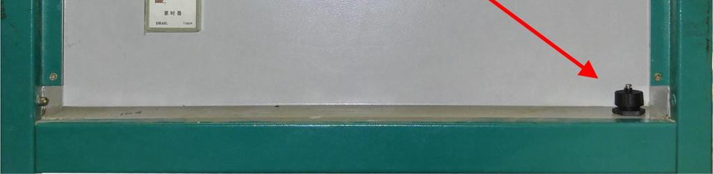
4 PAA CNC Control Retrofit Kit With marker and tape in hand, carefully remove and label each connector from the HI-800 CNC (the rectangular black box). Lay the cables to the sides so that you have unrestricted access to mount the new Electrical Panel (more tape!). Unbolt the HI-800 CNC and remove it from the Enclosure. Loosen the four (4) screws that will mount the Electrical Panel to the Enclosure. This allows the screws to wiggle a little and makes getting them into the slots in the Enclosure easier. Carefully lift the Electrical Panel into the Enclosure and guide the mounting screws into slots. Slip washers, lock-washers and nuts onto the screws but do not tighten them yet; first tighten the screws into the tapped holes in the Electrical Panel, then complete tightening the nuts. Cables Some repositioning of cables will be necessary because connector locations are different. Try to route cables so that they can be attached to the Enclosure with wire ties in such a way as to minimize the strain on the connectors and Converter Boards. Carefully secure the Axis connectors with the screws in the connectors shells. When connecting the 8-pole Euro connectors (IN5, IN6, OUT3, OUT4) try to squeeze them with your fingers rather than pushing, to avoid flexing the Converter Boards. The new Operator s Station Display requires different Video and Keyboard cables (included). Excess cable should be coiled and secured to the Enclosure with wire ties. The power cable for the CNC WILL reach if all restraining wire ties are cut and the cable rerouted. Alternatively, you can splice on an extra foot of cable. The power supply for the Operator s Station Display (LCD) is provided with a German (2-pin) plug. Although this can be plugged into the power strip in the Enclosure it is not recommended, as this power is not switched on and off with the CNC. A better solution is to cut off the plug and wire the cable to the same terminal blocks as the CNC power cable, or make a Y splice to power both the CNC and Display. The Display power supply can be secured to any convenient location with a wire tie or two. The supplied USB cable can be mounted in the existing hole in the Enclosure (see photo) and plugged into any USB port on the PA8000-LW CNC Control. Commissioning All appropriate configurations should have been pre-loaded before your kit was shipped. By convention backup copies of the configuration files are kept in various folders in the D:\PAData\ folder, and a master copy of the kit files is in the folder D:\Install\Configurations. A full set of Power Automation documentation (in PDF format) can be found in the folder D:\PA Documentation. PLC There are only two (2) options in the Flow WJP PLC, each controlled by setting a variable TRUE or FALSE, then compiling and installing the PLC: 4
 and no jumper on the connector then there will be a persistent error INLET WATER PRESSURE IS")
5 PAA CNC Control Retrofit Kit (*These are for configuration - enable both for Jplex with vac assist pressure control*) USE_WATER_SENSOR: BOOL:=TRUE; USE_TRISTATE_PRESSURE: BOOL:=FALSE; Water Pressure Sensor If there is no Water Pressure Sensor connected (to the INLET PRESSURE connector on the enclosure) and no jumper on the connector then there will be a persistent error INLET WATER PRESSURE IS TOO LOW.. To disable this test, change the variable USE_WATER_SENSOR to TRUE. Tri-State Pressure Control The LO/HI Water Pressure Button can be configured to act as either LO/HI (2 states) or OFF/LO/HI (3 states) depending on the value of the USE_TRISTATE_PRESSURE variable; FALSE = 2 States, TRUE = 3 States. NOTE! Read the following section concerning the FBWF before making any changes! Appendix A File-Based Write Filter (Windows Hard-Disk Protection) FBWF is a tool built into the Windows Operating System by Power Automation to reduce the chance of corrupting the Hard Disk Drive (volume C:, the System Drive). When enabled all writes to the disk are temporarily redirected to memory, and then discarded when the system is restarted. This prevents the system from becoming corrupted by viruses, unexpected shutdowns, careless users, etc. This means, however, that in order to make modifications to the system the FBWF must first be disabled, or all of your hard work will be discarded when you reboot! Older GUI Earlier builds of Windows Embedded automatically launch the Graphical User Interface (GUI) for the FBWF when you log in as Admin: 5
.")

6 PAA CNC Control Retrofit Kit Newer GUI More recent builds of Windows Embedded have an icon in the System Tray to launch the FBWF GUI, but you still must log into Windows as Admin in order to make changes to the FBWF. Disable / Enable the FBWF Log onto Windows using the Admin account (password PA009). In the lower-right corner of the screen is the System Tray area, in which you will find the Write Protect icon: Note that hovering your mouse over the padlock icon reveals the current state of the Write Filter; in the example to the left the C: drive is shown as Protected. Click the padlock icon to open the FBWF control panel. Note the first line ( State ) in the Overview: the Current setting is Enabled and the setting After Reset is also Enabled. This means that the FBWF will be enabled after rebooting. To make the state Disabled after the next reboot click the Configure button to open the FBWF Configuration Dialog. 6

7 PAA CNC Control Retrofit Kit Click the Filter state enabled checkbox to un-check it: Then click the OK button to return to the previous dialog. Note that now the After restart state is Disabled, although the Current state is still Enabled. Click the Close button. From the Start button select Restart to re-boot Windows. 7


8 PAA CNC Control Retrofit Kit When Windows restarts you can verify that the FBWF is not active by hovering your mouse over the padlock icon in the System Tray: Once you have made any changes and verified correct operation you should enable the FBWF by following the preceding steps, this time checking the Filter state enabled checkbox. After restarting Windows verify that the FBWF is actively protecting the C: drive by hovering your mouse over the padlock icon in the System Tray: Remember to instruct the customer to NEVER try to save ANYTHING to the C: drive! 8


 connectors are DB15-S sockets and carry ONLY the encoder signals and power.")

9 PAA CNC Control Retrofit Kit Appendix B Adapter Cards Overview The Higerman HI-800 CNC Control was built using core technology originally licensed from Power Automation, but with non-compatible hardware. In order to adapt standard Power Automation hardware to replace the Higerman HI-800 several electrical differences had to be addressed. PA I/O logic is sourcing ; outputs supply +24 VDC when active, inputs require +24 VDC to be turned on. Higerman logic is sinking ; outputs sink to 24-volt common, inputs are pulled to 24-volt common to be turned on. PA axis (encoder) connectors are DB15-S sockets and carry ONLY the encoder signals and power. Analog command signals are all on one (separate) plug-in connector. Higerman axis connectors are HD26-S sockets and carry, in addition to the encoder signals, the analog command for each axis and some miscellaneous digital I/O signals. Power Automation America has developed a set of converter boards that solve these connection and logic-level problems without the use of additional relays, breakout boards, etc. Axis Board 9
10 PAA CNC Control Retrofit Kit Input / Output Boards 10


11 PAA CNC Control Retrofit Kit Appendix C Photographs Flow built several variations of the Waterjet Pro series, and there seems to have been considerable variation in wire and cable routing from machine to machine, even of the same model. The photographs that follow, therefore, represent the general practices to be followed, not the exact appearance of any particular machine. Indeed, they are a compilation of several different models and builds. The pictures illustrate several stages of the retrofit project, starting with an un-modified WJP-1313 enclosure. Kit Contents 11


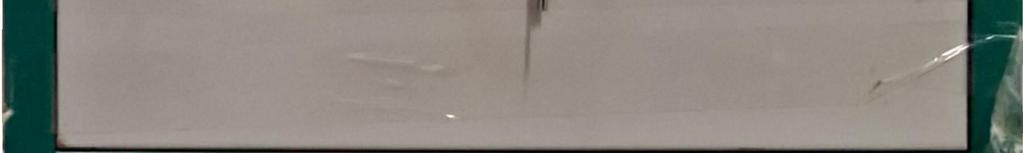
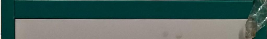


12 PAA CNC Control Retrofit Kit Enclosure, Front and Rear Views (before installation) 12


")
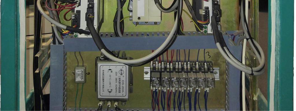
13 PAA CNC Control Retrofit Kit HI800 CNC Control PA8000-LW CNC Control (as installed) 13


")
14 PAA CNC Control Retrofit Kit Enclosure (Rear) After Installation 14


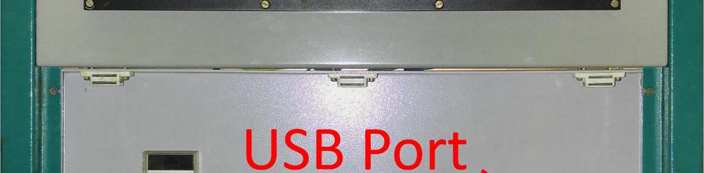
15 PAA CNC Control Retrofit Kit Operator s Station (after installation) 15
16 PAA CNC Control Retrofit Kit Appendix D Wiring Diagrams There are two (2) basic variations of this kit: without Gantry (3 axis motors and drives) and with Gantry (4 axis motors and drives). Currently these are for use with WJP-1313 and WJP-1318 (no Gantry) and WJP-2031 (with Gantry). The designs are substantially similar, but the non-grantry version uses a 5-volt Handwheel connected via the fourth RMS channel of the CNC whereas the Gantry version uses a 24-volt Handwheel connected via the digital inputs IN3.7 and IN3.8 (because all four RMS channels are used for motors). The diagrams for your version (with or without Gantry) are provided separately from this document. 16
A Axis M-Functions Level 1 A Axis Standard A Axis SMT Level 2. Each console includes the following:
 Hardware List The 3000M Crusader II Upgrade system has been custom configured to provide the necessary hardware required for installation on your machine. Verify that you have received all the correct
PracticeWire. Field Support: Page 1
 PracticeWire Field Support: 1-877-233-9114 Page 1 Table of Contents Required Tools Page 3 Software Hardware 1) Admin Login.... Page 3 2) Checking AT&T signal strength Page 3 3) Port test.. Page 4 1) Cradlepoint
Section. Service & Maintenance. - Core & Hard Disk Drive (HDD) - Amplifier - Monitor - UPS - Dollar Bill Acceptor - Fan Filter G - 1
 - Amplifier - Monitor - UPS - Dollar Bill Acceptor - Fan Filter G - 1") Section G Service & Maintenance - Core & Hard Disk Drive (HDD) - Amplifier - Monitor - UPS - Dollar Bill Acceptor - Fan Filter G - 1 Core Removal Core & HDD 1. Open the door. 2. Perform shutdown procedure.
Section G Service & Maintenance - Core & Hard Disk Drive (HDD) - Amplifier - Monitor - UPS - Dollar Bill Acceptor - Fan Filter G - 1 Core Removal Core & HDD 1. Open the door. 2. Perform shutdown procedure.
G12/G12x USER S MANUAL
 G12/G12x USER S MANUAL TABLE OF CONTENTS SECTION 1 SLIDE CONFIGURATION SECTION 2 SLIDE CONFIGURATION ACCESSORIES SECTION 3 TABLETOP CONFIGURATION SECTION 4 TABLETOP CONFIGURATION ACCESSORIES SECTION 5
Installing and Removing SDRAM and DRAM
 CHAPTER 4 This chapter explains how to remove and replace the main memory modules on the network processing engine or network services engine. For the location of the memory module you are replacing, find
Installation Guide. Retrofit Kit for USB Ready Intraoral Systems
 Installation Guide Retrofit Kit for USB Ready Intraoral Systems Table of Contents Wall-Mount Retrofit Kit... 2 Introduction... 2 Connecting the Articulating and Horizontal Arm Cables... 2 Installing the
Control Box Setup - PRSalpha
 888-680-4466 ShopBotTools.com Control Box Setup - PRSalpha Copyright 2016 ShopBot Tools, Inc. page 1 Copyright 2016 ShopBot Tools, Inc. page 2 Parts List: Hooking Up a PRSalpha Gantry Tool Powering the
REMOTE HEAD ADAPTER INSTALLATION GUIDE
 REMOTE HEAD ADAPTER INSTALLATION GUIDE The Remote Head adapter is a valuable accessory for the Uniden BC-780, 785 and 796 scanners. It allows the scanner's control panel to be removed from the radio and
EMC 10T "CE" Mechanical Upgrade Procedure
 EMC 10T "CE" Mechanical Upgrade Procedure Kit Part Number: 009866-01 This procedure upgrades a non-ce compliant machine to the mechanical requirements of a CE compliant machine. Properly upgraded machines
Replacing the Galaxy II CRT Monitor with a Flat Screen Monitor Kit # 42638
 Replacing the Galaxy II CRT Monitor with a Flat Screen Monitor Kit # 42638 This kit contains detailed instructions on removing a Galaxy II Daewoo monitor and replacing it with a 19 wide flat screen monitor.
imac Intel 27" EMC 2639 Hard Drive
 imac Intel 27" EMC 2639 Hard Drive Replacement Replace the Hard Drive in your imac Intel 27" EMC 2639. Written By: Walter Galan ifixit CC BY-NC-SA www.ifixit.com Page 1 of 26 INTRODUCTION Replacing the
TABLE OF CONTENTS SECTION 1 TABLETOP CONFIGURATION SECTION 2 TABLETOP CONFIGURATION ACCESSORIES SECTION 3 SLIDE CONFIGURATION
 S6 USER S MANUAL TABLE OF CONTENTS SECTION 1 TABLETOP CONFIGURATION SECTION 2 TABLETOP CONFIGURATION ACCESSORIES SECTION 3 SLIDE CONFIGURATION SECTION 4 SLIDE CONFIGURATION ACCESSORIES SECTION 5 RACK MOUNT
OnePlus 5 Screen and Digitizer Assembly Replacement
 OnePlus 5 Screen and Digitizer Assembly Replacement Follow this guide to replace the screen and digitizer for the OnePlus 5. This replaces the screen as well as the frame it is attached to. Written By:
Eaton LCD Lift Flat Panel Display System. Installation Guide
 Eaton LCD Lift Flat Panel Display System Eaton LCD Lift Flat Panel Display System Installation Guide Copyright 2011 Eaton Corporation, Worcester, MA, USA. All rights reserved. Information in this document
IMPORTANT AS YOU REMOVE THE CONNECTORS LABEL THE CONNECTOR WITH THE NAME OF PLUG WITH THE SHARPIE
 TOOLS REQUIRED : small flat head screwdriver no wider than ⅛ or 3mm wide, phillips head screwdriver, 3mm allen wrench, self tapping screws #6 x ½, ¼ hex head driver, electric drill, wire cutters, fine
AC300/AC400 SERIES DYNAMIC BRAKING and ADDITIONAL FORM C RELAY. INSTALLATION INSTRUCTIONS Document Number:
 Minarik Variable Speed AC Motor Drives AC300/AC400 SERIES DYNAMIC BRAKING and ADDITIONAL FORM C RELAY INSTALLATION INSTRUCTIONS Document Number: 250-0297 These instructions apply to models rated: 7.5 25
Installing a Power over Ethernet injector
 Installing a Power over Ethernet injector AlphaEclipse StreetSmart and RoadStar signs The instructions in this document explain how to install/replace a Power over Ethernet (PoE) injector in a StreetSmart
Upgrading a 2U CHP to an i7 Quad Core SBC
 Upgrading a 2U CHP to an i7 Quad Core SBC 1. Parts required: i7 SBC Slim line SATA DVD drive Combined SATA data and power cable for slim-line optical drive Serial port ribbon cable - 9way D male to 10
PS/IO Circuit Board Retrofit
 S&C 6800 Series Automatic Switch Controls PS/IO Circuit Board Retrofit Table of Contents Section Page Introduction Qualified Persons.... 2 Read this Instruction Sheet.... 2 Retain this Instruction Sheet....
Removing and Replacing Parts
 Removing and Replacing Parts Preparing to Work Inside the Computer Recommended Tools Screw Identification System Components Hard Drive Fixed Optical Drive Media Bay Devices Memory Modules Mini PCI Card
Revised: Page 1
 Brought To You By And Designed By: Revised: 2017-05-07 Page 1 Features Of The Universal PSU Kit: Fits all standard Apple II and /// Power Supply Enclosures. (all parts included, user supplies household
imac Intel 27" Retina 5K Display CPU Replacement
 imac Intel 27" Retina 5K Display CPU Replacement Replace or upgrade the CPU in your imac Intel 27" Retina 5K Display. Written By: Sam Lionheart ifixit CC BY-NC-SA www.ifixit.com Page 1 of 36 INTRODUCTION
TECHKNOW, INC. Kiosk Order Confirmation System INSTALLATION MANUAL. Revision Date: July 11, 2012 Part # Version 3.2
 document Page 1 of 18 TECHKNOW, INC Kiosk Order Confirmation System INSTALLATION MANUAL Revision Date: July 11, 2012 Part # Version 3.2 Techknow, Inc. 393 Mayfield Road Duncan, SC 29334 www.gotechknow.com
E1135C PDU and Pod Upgrade Procedure
 E4030-90010 Rev. B 12/2003 In this Document... Tools Needed, 2 Contents of the Upgrade Kits, 2 Installation Procedures, 4 Verifying the Power Option of the New PDU, 4 Removing the PDU from the Support
Figure 4-29 Removing the CPU compartment cover
 4 Replacement Procedures 4.9 CPU 4 4.9 CPU Removing the CPU To remove the CPU, follow the steps below. 1. Turn the computer upside down and remove two M2.5 4 security screws securing the CPU compartment
1. Carefully unpack the um260 s shipping carton and check the contents for damage.
 um260 Installation Manual um260 Installation Chapter 4 um260 MICRO MONITOR INSTALLATION This section of the um260 Micro Monitor Installation Manual describes the requirements and procedures for installing
Removal and Installation8
 8 Screw Types 8-4 Top Cover Assembly 8-5 Left Hand Cover 8-6 Right Hand Cover 8-10 Front Panel Assembly 8-14 Left Rear Cover 8-15 Right Rear Cover 8-16 Extension Cover (60" Model only) 8-17 Media Lever
Z-Truck (Vertical Moving) Z-truck Flag. Y-Truck (Horizontal Moving) FIGURE 1: VIEW OF THE Z-TRUCK. Flexshaft Assembly
 Z-truck Flag. Y-Truck (Horizontal Moving) FIGURE 1: VIEW OF THE Z-TRUCK. Flexshaft Assembly") Replacing the LCD Cable To remove and replace the LCD Cable you will need the following tools: #2 Phillips screwdriver (magnetic tip preferred) Socket wrench with 10mm socket Removing the Side Panel 1.
Replacing the LCD Cable To remove and replace the LCD Cable you will need the following tools: #2 Phillips screwdriver (magnetic tip preferred) Socket wrench with 10mm socket Removing the Side Panel 1.
DirectCommand Installation CASE IH SPX Ag Leader Technology. PN: Rev. E January 2014 Page 1 of 19
 Note: These installation instructions only cover installation on SPX 4420 Sprayers only. For installation on SPX 3230/3330 Sprayers refer to Installation Instructions P/N 2005945. For SPX 4430 refer to
TDM To MiniMech conversion ProceDure
 TDM To MiniMech conversion ProceDure (Model 9100 ATM) TDN 07102-00079 Apr 1 2009 CorporATe HeAdquArTers: 522 E. Railroad Street Long Beach, MS 39560 PHONE: (228) 868-1317 FAX: (228) 868-0437 COPYRIGHT
Treadmill Integrated LCD Screen Option. Cardio Theater Integrated Bracket Assembly Instructions
 Treadmill Integrated LCD Screen Option Cardio Theater Integrated Bracket Assembly Instructions Table of Contents 1 2 3 4 5 6 Before You Begin... 4 Obtaining Service... 4 Unpacking the Equipment... 4 Important
HARMONi G3. Quick Start Guide for HARMONi G3. imac Processor/FireWire Upgrade
 HARMONi G3 imac Processor/FireWire Upgrade imac and Operating System Compatibility The HARMONi G3 imac processor/firewire upgrade is compatible only with imac 233, 266, and 333 MHz models (Revisions A-D);
Assembly and Setup Manual
 M-12 Series Copyboard / C-12 Series Captureboard Assembly and Setup Manual This is the installation and assembly manual for the M-12 series Copyboard and C-12 series Captureboard. (The copyboard and/or
Cycles Integrated LCD Screen Option. Cardio Theater Integrated Bracket Assembly Instructions
 Recumbent Upright Cycles Integrated LCD Screen Option Cardio Theater Integrated Bracket Assembly Instructions Table of Contents 1 2 3 4 5 6 7 Before You Begin... 4 Obtaining Service... 4 Unpacking the
TASER Axon Dock Installation Manual IMPORTANT SAFETY INSTRUCTIONS
 TASER Axon Dock Installation Manual IMPORTANT SAFETY INSTRUCTIONS Read all warnings and instructions. Save these instructions. The most up-to-date warnings and instructions are available at www.taser.com
RAM Rail Mount Kit RAM 201U 5 Arm RAM 2461U Monitor Mount RAM 235U Base, Double U-Bolt
 Note: Indented items indicate parts included in an assembly listed above Part Name/Description Part Number Quantity DirectCommand Kit 4100800 1 Cable Installation Kit 2000901-1 1 Dielectric Grease 2002872
Installing the Server into a Rack
 Installing the Server into a Rack Note These instructions apply to multiple models; illustrations may vary slightly. Rack Mount Kit Inventory Before installing the chassis on a standard 4-post rack, make
SITRANS F. Flowmeters SysCom Upgrade Kit IP65 (NEMA 4X) Multi-Channel. Introduction 1. Installing/Mounting 2. Hardware Installation Instructions
 Multi-Channel. Introduction 1. Installing/Mounting 2. Hardware Installation Instructions") Introduction 1 Installing/Mounting 2 SITRANS F Flowmeters SysCom Upgrade Kit IP65 (NEMA 4X) Multi-Channel Hardware Installation Instructions 1/2010 A5E02518333A Revision 04 Legal information Warning notice
Introduction 1 Installing/Mounting 2 SITRANS F Flowmeters SysCom Upgrade Kit IP65 (NEMA 4X) Multi-Channel Hardware Installation Instructions 1/2010 A5E02518333A Revision 04 Legal information Warning notice
Plasma Panel Replacement Guide DU-42PX12X
 Plasma Panel Replacement Guide DU-42PX12X Panel Replacement: At this point, the panel has been determined to be defective and replacement is necessary. Upon receiving the replacement panel, it must be
Components. Tools for Setup. Installation Outline
 VANTAGE PRO AND VANTAGE PRO PLUS Fan-Aspirated ISS Retrofit Kit Installation Instructions Estimated Time Required: 60 Minutes These instructions describe how to install the Vantage Pro Fan-Aspirated Integrated
Phase Loss Protection Upgrade. Phase Loss Protection Upgrade. In this bulletin:
 Phase Loss Protection Upgrade In this bulletin: Introduction... 2 Purpose... 2 General... 2 Applicability... 2 HD3070 Phase Loss Protection Upgrade Kit Parts... 2 Preparation... 4 Install the Phase Loss
Smart Multivariable Transmitter (SMV 3000) Electronics Module Replacement Kit Instruction
 Electronics Module Replacement Kit Instruction") Smart Multivariable Transmitter (SMV 3000) Electronics Module Replacement Kit Instruction Electronics Module (Part number 51404208 503, -513) Document Form: 34-SM-33-01 Effective: 09-01 Supersedes: 34-SM-33-01,
Smart Multivariable Transmitter (SMV 3000) Electronics Module Replacement Kit Instruction Electronics Module (Part number 51404208 503, -513) Document Form: 34-SM-33-01 Effective: 09-01 Supersedes: 34-SM-33-01,
S E R V I C E N O T E
 IINFORMATIION ONLY S E R V I C E N O T E Supersedes: MSO8104A-05 MSO8104A Digitizing Oscilloscope Serial Numbers: MY00000000-MY46001900 SG00000000-SG46001900 The original scopes motherboard is no longer
Model ver INSTALLATION MANUAL Rev CHD Elektroservis
 Model 8-435 ver. 1.0 INSTALLATION MANUAL Rev. 2 7 2018 CHD Elektroservis Contents page 1 INTRODUCTION.................................................................. 3 1.1 MIDI INTERFACE KIT PARTS.......................................................
Cellular Shades MOTORIZED SKYLIGHT. Simplicity with rechargeable batteries. Installation & Care Instructions
 Cellular Shades MOTORIZED SKYLIGHT Simplicity with rechargeable batteries Installation & Care Instructions 152741B 7/2/2018 GETTING STARTED A few simple tools are required: - Measuring tape - Power drill,
Floppy Disk To USB. Converter Installation and. Operation Manual
 Floppy Disk To USB Converter Installation and Operation Manual Kit Price $125.00 Plus Shipping Why Should I Change My Floppy Drive To A USB Drive? You won't ever need floppies anymore and yet you'll be
Installation Instructions
 Time Commander II Electronic Time Lock Installation Instructions This Sargent & Greenleaf Time Commander II electronic time lock combines ease of operation with security. Advanced electronic circuit design
Pandora Assembly Instructions With Diamond Systems PC/104 CPUs (Athena, Elektra and Prometheus) November, 2006
 November, 2006") Pandora Assembly Instructions With Diamond Systems PC/104 CPUs (Athena, Elektra and Prometheus) November, 2006 Diamond Systems Corp. (650) 810-2500 www.diamondsystems.com This document describes how to
Pandora Assembly Instructions With Diamond Systems PC/104 CPUs (Athena, Elektra and Prometheus) November, 2006 Diamond Systems Corp. (650) 810-2500 www.diamondsystems.com This document describes how to
Assembly and Setup Manual
 M-11 Series Copyboard/C-11 Series Captureboard Assembly and Setup Manual This is the installation and assembly manual for the M-11 series/c-11 series. To the Customer Specialized techniques are required
Field Update Guide. for Raven Viper Pro
 Field Update Guide for Raven Viper Pro Introduction The field update kit (P/N 117-0171-467) is designed to allow the Raven Viper Pro to utilize the automatic power down feature without returning the console
V5420 Host Card Upgrade Kit for R3082D Quick Start Guide
 Quick Start Guide Upgrade kit contents The table below shows the contents of the V5420 Host Card Upgrade Kit (components are not shown to scale). Part Function Pieces V5420 Host Card 1 Host card bracket
Replacing the PanelMate Power Pro 1785 Series, PanelMate epro 7585x-8 and 7685x-8 Series Backlight Assembly
 Replacing the PanelMate Power Pro 1785 Series, PanelMate epro 7585x-8 and 7685x-8 Series Assembly Introduction The Replacement Kit provides a replacement backlight for the PanelMate Power Pro 1785 Series,
How to add a Second Drive to a Mac mini (2012) using the OWC Data Doubler SSD/2.5 Installation Kit
 using the OWC Data Doubler SSD/2.5 Installation Kit") Instructional Video Series How to add a Second Drive to a Mac mini (2012) using the OWC Data Doubler SSD/2.5 Installation Kit Skill Level: Challenging Time to Complete: Approximately 45 Minutes Required
Instructional Video Series How to add a Second Drive to a Mac mini (2012) using the OWC Data Doubler SSD/2.5 Installation Kit Skill Level: Challenging Time to Complete: Approximately 45 Minutes Required
Raven Adapter Harness
 Note: Indented items indicate parts included in an assembly listed above Quantity by System Part Name/Description Part Number With Switch Box With Built-in Switches Raven Harness Adapter Kit 4100504 1
WaveRider Installation
 WaveRider Installation Single Washer Serial Mode (MDC & Quantum) PREP FOR COIN CARD ONLY OPERATION Coin Box Mount 2115 Chapman Road, Suite 159, Chattanooga TN 37421 800.332.4835 Laundry Machine Types This
Written By: Walter Galan
 imac Intel 17" Power Supply Replacement Written By: Walter Galan ifixit CC BY-NC-SA www.ifixit.com Page 1 of 18 INTRODUCTION Power hungry? Keep those electrons flowing by replacing your power supply. TOOLS:
QUICK START GUIDE. Android or Windows Tablet. 1 Tower PC. Mount the RazorGage to your Own Table. Assembling the RazorGage ST with RazorGage Table
 QUICK START GUIDE Android or Windows Tablet If you have a Tablet Style Interface (PC or Android) then skip this step. 1 Mount monitor and attach legs to control tower using hardware provided and place
SERVICE PARTS MANUAL
 SERVICE PARTS MANUAL 8 SERIES SNOW PLOW FOR SERIAL NUMBERS AFTER 8D100000 00 Sno-Way International 9100G TABLE OF CONTENTS PAGE DEFLECTORS... POWER PACK... HYDRAULIC POWER UNIT... LIFT CYLINDER... ANGLE
Description: Detailed procedure on removing old bushing and installing new Brake Bushing Replacement Kit 10447
 Procedure: BRAKE BUSHING REPLACEMENT PROCEDURE Product: Document #: Rev: Page: MODEL 7000, 7000A, & 8000 GYRO 078 1 1 of 14 Description: Detailed procedure on removing old bushing and installing new Brake
Unpacking and Installing the Flora 2512 UV Printer. Steps 1: Unscrew the 10mm bolts holding the top. Then remove the top and put in a safe place.
 Unpacking and Installing the Flora 2512 UV Printer Steps 1: Unscrew the 10mm bolts holding the top. Then remove the top and put in a safe place. Step 2: Unscrew 10mm bolts holding the end panels. On the
GM NBS Truck CCD Backup Camera Kit Installation Guide
 CS GM1 GM NBS Truck 2007 2012 CCD Backup Camera Kit Installation Guide Thank you for your purchase! These instructions are intended for the do it yourselfer who decides to install the camera without professional
The guide for the replacement of a factory stock radio. Installation may vary if stock radio has been replaced.
 1_ INSTALLATION The guide for the replacement of a factory stock radio. Installation may vary if stock radio has been replaced. Included in Kit: Handle-Bar Control Module [HCM] Radio Conrtrol Module [RCM]
INSTALLATION MANUAL DATAVAULT DATAVAULT - BARE JOBSITE STORAGE SOLUTIONS
 JOBSITE STORAGE SOLUTIONS ALWAYS ON THE JOB INSTALLATION MANUAL 118-01 DATAVAULT 118-02 DATAVAULT - BARE Werner Co. 724-588-2000 93 Werner Rd. 888-523-3371 toll free/ llamada gratuita Greenville, PA 16125
Paramount Electronics Replacement Instructions
 Paramount Electronics Replacement Instructions Revision 1.7, October 2017 2017 Software Bisque, Inc. All rights reserved. Contents Replacing Paramount Electronics... 3 Step 1: Save Existing Control System
INSTALLATION INSTRUCTIONS
 INSTALLATION INSTRUCTIONS 19 20 21 01 07 22 23 13 10 12 08 17 18 11 02 14 15 04 03 16 WELCOME PARTS LIST Thank you for purchasing this HealthPoint Technology Cabinet from Humanscale! Before you begin installing
Written By: Walter Galan
 Replace a cracked screen on your iphone 4S. Written By: Walter Galan ifixit CC BY-NC-SA www.ifixit.com Page 1 of 32 INTRODUCTION Use this guide to replace the screen on your iphone 4S. After successfully
RAM Rail Mount Kit RAM 201U 5 Arm RAM 2461U Monitor Mount RAM 235U Base, Double U-Bolt
 DirectCommand Installation Ag Leader Technology Note: Indented items indicate parts included in an assembly listed above Part Name/Description Part Number Quantity DirectCommand Kit 4100852 1 Cable Installation
Rack Installation Instructions
 Rack Installation Instructions For System Storage EXP2512 and EXP2524 Express Storage Enclosures Use the instructions in this document to install an IBM System Storage EXP2512 Express Storage Enclosure
imac Intel 20" EMC 2266 Optical Drive
 imac Intel 20" EMC 2266 Optical Drive Replacement Replace the optical drive in your imac Intel 20" EMC 2266. Written By: Dozuki System 2017 guides.crucial.com Page 1 of 16 INTRODUCTION DVD writer not writing?
SSD Dual Drive Installation
 SSD Dual Drive Installation Replace the optical drive in your imac Intel 21.5". Written By: Dozuki System 2017 guides.crucial.com Page 1 of 18 INTRODUCTION imac won't read disks? Use this guide to replace
7" Touch Screen Display
 7" Touch Screen Display Installation Guide Contents Minimum Requirements...1 Select a Location...1 Initial Setup...2 Unboxing...2 Installation...3 Prepare the Panel...3 Install the Mounting Plate...3 Mount
Shop Fox Fence Kit Installation Instructions:
 Shop Fox Fence Kit Installation Instructions: Please note this installation kit is designed solely for installation on a Shop Fox Classic Fence. Accurate Technology manufactures kits for other saw fences
Installation Instructions. Ecast Mojo B75B Motherboard Upgrade Kit Kit #
 Installation Instructions Ecast Mojo B75B Motherboard Upgrade Kit Kit #26684501 This kit contains the parts and instruction to install the B75B Motherboard into your Ecast Mojo jukebox. Tools Required
Installation Instructions
 Installation Instructions Ecast EQ to AMI hardware conversion KIT #26683701 This kit is for use in Ecast EQ jukeboxes. Tools Required #2 Phillips screw driver, #1 Phillips screw driver, Small flat blade
apple Service Source Apple Cinema Display 22" LCD (ADC) 11 April Apple Computer, Inc. All rights reserved.
 11 April Apple Computer, Inc. All rights reserved.") apple Service Source Apple Cinema Display 22" LCD (ADC) 11 April 2003 2003 Apple Computer, Inc. All rights reserved. apple Service Source Take Apart Apple Cinema Display 22" LCD (ADC) 2003 Apple Computer,
apple Service Source Apple Cinema Display 22" LCD (ADC) 11 April 2003 2003 Apple Computer, Inc. All rights reserved. apple Service Source Take Apart Apple Cinema Display 22" LCD (ADC) 2003 Apple Computer,
C764i Integrated LCD Screen Option. Cardio Theater Integrated Bracket Assembly Instructions
 C764i Integrated LCD Screen Option Cardio Theater Integrated Bracket Assembly Instructions Table of Contents 1 2 3 4 5 6 7 Before You Begin... 3 Obtaining Service... 3 Unpacking the Equipment... 3 Important
Assembly Instructions
 Assembly Instructions Flat Screen Garage End User & IT Computer Cable Management May 2013 nylon zip-tie #2 (for computer wires) rear-access beam door (open) Figure 1 nylon zip-tie #1 (for #1 motor control
Oracle <Insert Picture Here>
 Slide 1 Oracle Slide 2 WZT-6509 version B Sun Fire Nehalem and Westmere Rack-Mount Server Installation and Replacement Welcome to the installation and replacement
Royal RVV-500 (B) Retrofit Kit
 Retrofit Kit") Optipay BV/RC/CC into a Non-Fascia Vending Machine This document contains information for installing and configuring the JCM Optipay DBV-01 Bill Validator, RC-10 Bill Recycler and A-66 Coin Changer into
Optipay BV/RC/CC into a Non-Fascia Vending Machine This document contains information for installing and configuring the JCM Optipay DBV-01 Bill Validator, RC-10 Bill Recycler and A-66 Coin Changer into
imac Intel 27" Retina 5K Display SATA Cable
 imac Intel 27" Retina 5K Display SATA Cable Replacement Written By: Dozuki System 2017 guides.crucial.com Page 1 of 32 INTRODUCTION Use this guide to replace the SATA cable on the back of the logic board
USBCNC USB Disk Key reader for CNC Controls Machine Mount instructions
 USBCNC USB Disk Key reader for CNC Controls Machine Mount instructions 2008-2015 Calmotion LLC, All rights reserved Calmotion LLC 21720 Marilla St. Chatsworth, CA 91311 www.calmotion.com Introduction This
INSTALLATION INSTRUCTIONS Version 2.4
 INSTALLATION INSTRUCTIONS Version 2.4 11/12/2012 Patient Point, LLC 8230 Montgomery Road, Suite 300 Cincinnati, Ohio 45236 1-800-287-0908 TABLE OF CONTENTS System Overview 2 Tool List. 3 Installation Process
Service Bulletin. MiTek. RoofTracker Roof Truss Roller Press. Machinery Affected: Adding an Operator Platform. Machinery Division
 MiTek Machinery Division Service Bulletin Machinery Affected: Document: Title: Applies To: RoofTracker Roof Truss Roller Press SB171 Adding an Operator Platform Frames 51 and Lower Copyright 2006 MiTek.
HGR-2488 Prism Installation Instructions
 HGR-2488 Prism Installation Instructions These installation instructions are applicable to the following models: TASCAM 2488 MK1 (original model) TASCAM 2488 MK II TASCAM 2488 NEO Page 1 of 8 Important
Mac Mini Mid 2011 SSD Dual Drive Installation
 Mac Mini Mid 2011 SSD Dual Drive Installation Install a second hard drive in your mid 2011 Mac Mini. Written By: Dozuki System 2017 guides.crucial.com Page 1 of 19 INTRODUCTION Use this guide to install
SERVICE PARTS MANUAL
 SERVICE PARTS MANUAL DX SERIES SNOW PLOW FOR SERIES SNOW PLOWS SERIAL NUMBERS AFTER DX0000 00 Sno-Way International 0G TABLE OF CONTENTS Page HYDRAULIC SYSTEM (DX)... POWER PACK FRAME... 3 BLADES... LIFT
Note: These installation instructions are only for the 4430/4440 Sprayer. For other SPX models please refer to P/N , &
 DirectCommand Installation Ag Leader Technology Note: These installation instructions are only for the 4430/4440 Sprayer. For other SPX models please refer to P/N 2005944, 2005945 & 2006383. Part Name/Description
PowerView Model PV485. Installation Manual Section 78
 PowerView Model PV485 Installation Manual 00-02-1018 2017-05-23 Section 78 In order to consistently bring you the highest quality, full-featured products, we reserve the right to change our specifications
Whitebox TM Developer s Guide
 Whitebox TM Developer s Guide Revision 1.0 April 22, 2016 c 2016 Arx Pax Labs, Inc. 1 Contents 1 Introduction 3 2 Equipment Not Included 3 3 How to Disassemble the Whitebox 4 4 ESC Programming 9 5 Teensy
Optional Accessories 6 2
 Accessories Chapter 6 Table of Contents Optional Accessories 6 2 Finger Guards 6 2 Remote Touchscreen 6 3 RJ45 to RJ12 Adapter 6 5 Serial Modbus Communication Splitter 6 5 Communication Modules 6 7 Replacement/Spare
To connect the AC adapter:
 Replacing the AC Adapter Replacing the AC Adapter 3 Plug the power cord into a wall outlet. The power indicator turns on. To connect the AC adapter: Connect the power cord to the AC adapter. Power indicator
When you are ready to build your computer you will have the following materials to work with.
 Copyright 2009 BOSMA Enterprises Chapter 3 Putting the Computer Together When you are ready to build your computer you will have the following materials to work with. 1. One motherboard. 2. One ribbon
Encore XT Manual Gun Upgrade Kit
 Instruction Sheet P/N 1600823-01 Encore XT Manual Gun Upgrade Kit 1600834 Introduction Follow these instructions to upgrade your Encore manual spray gun to the improved design of the Encore XT spray gun.
into the EMU E4 Classic and E4 Platinum Samplers
 Installing the CF-CARD SCSI Card Reader/Writer Drive into the EMU E4 Classic and E4 Platinum Samplers Thank you for purchasing the CF-CARD Internal Card Reader Drive Installation Kit from SCSICardReaders.com.
Reference Manual VL-ENCL-5. Development Enclosure DOC. REV. 4/9/2013
 Reference Manual DOC. REV. 4/9/2013 VL-ENCL-5 Development Enclosure WWW.VERSALOGIC.COM 12100 SW Tualatin Road Tualatin, OR 97062-7341 (503) 747-2261 Fax (971) 224-4708 Contents Copyright 2013 All Rights
Navigator II INstallatIoN MaNUal For static and PaN/tIlt configurations
 Navigator II Installation MANUAL For Static and Pan/Tilt Configurations Document Number: 432-0001-00-12, rev 100 FLIR Systems, Inc., 2008. All rights reserved worldwide. No parts of this manual, in whole
imac Intel 27" EMC 2546 Adhesive Strips
 imac Intel 27" EMC 2546 Adhesive Strips Replacement Reattach your display with a set of adhesive foam strips. Written By: Andrew Optimus Goldberg ifixit CC BY-NC-SA www.ifixit.com Page 1 of 18 INTRODUCTION
System Storage EXP3000 Rack Installation Instructions
 System Storage EXP3000 Rack Installation Instructions Review the documentation that comes with your rack cabinet for safety and cabling information. When you install the IBM System Storage EXP3000 in a
SKYLEVEL INSTALLATION Manual
 SKLEVEL INSTALLATION Manual Southwest Windpower, Inc. 80 West Route 66 Flagstaff, Arizona 8600 USA Phone: 928-779-9463 Fax: 928-779-485 www.skystreamenergy.com June 2009 Southwest Windpower, Inc. All Rights
PoE/FPR Kit for Auto-Sync Time Clock. The Auto-Sync Time Clock is a validated time system with a Web interface and auto discovery.
 ASTCPOEK PoE/FPR Kit for Auto-Sync Time Clock The Auto-Sync Time Clock is a validated time system with a Web interface and auto discovery. The ASTCPOEK Kit provides Power over Ethernet with Full Power