ADP15 Versatile Indicator/Controller
|
|
|
- Tyler Houston
- 6 years ago
- Views:
Transcription

1 ADP15 Versatile Indicator/Controller User Manual
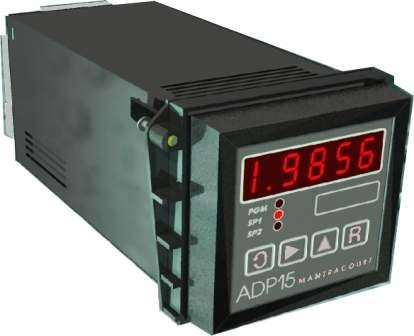
2 The ADP15 Quick User Guide The Front Control Panel All user controls, displays and indicators are mounted on the front panel which provides a 4.5 digit, LED display four flush mounted keys and three LED indicators. The front panel components are identified as follows:- D1-1/2 digit D2 - Decade 1 D3 - Decade 2 D4 - Decade 3 D5 - Decade 4 PGM - Program Mode SP1 - Set Point 1 SP2 - Set Point 2 Front Panel Guide d b Used to scroll through and change the set up data by displaying mnemonics for each configurable parameter, followed by the appropriate data. When in programming mode it should be noted that the first digit in the display may not be visible, but the program indicator light PGM will be flashing to indicate that the instrument is in programming mode, even though no digits can be seen to be flashing. The d key has a secondary function when not in programming mode. In conjunction with the b key a print function can be initiated. (If a print option is fitted.) The d key has a secondary function when not in programming mode. In conjunction with the b key a print function can be initiated. (If a print option is fitted.) Selects the display digit required. Selection value is indicated by a flashing digit and flashing PGM indicator light. It also operates as a control key in conjunction with: The d key for a print function from the rear panel remote. The c key for Peak Hold / Latched Relay Reset The a key for an Count Reset function. c a Increments each selected display digit 0-9. Pressing the c key under programming conditions will display the leading digit as either 1, -1, or a blank display for zero. The secondary function operates as a Peak Hold / Latched Relay Reset in conjunction with the b key. Resets the display to the input variable and enters new data in the ADP15-FPT memory. Returns the display to the current value after Hold. The secondary function operates an Count Reset in conjunction with the b key NOTE: Secondary functions require the b key to be pressed and released, followed within 1 second by the appropriate function key. b then d for Print Select b then c for peak Hold/Latched Relay Reset b then a for Count Reset If during the programming sequence, selection is not completed, the display will revert to the input variable after 30 seconds. The display module is fitted with 2 security links which, when removed, allows the user to disable keypad programming. The Configurable Parameters These parameters or programmable functions are provided in the ADP to allow the user good flexibility for monitor and control applications. Parameters are included as constants in the ADP database and are accessed and checked via the keypad or the communications port. Data which is entered by the user is retained by EEPROM for up to 10 years without back up power. New data, when entered, overwrites previous entries when the a or d key is pressed unless the EEPROM has been disabled via the communications port. 1 Mantracourt Electronics Limited ADP User Manual
3 Configurable Parameters DISPLAY FUNCTION RANGE FUNCTION SP1 Set Point 1 ±19999 Sets first output trip or control SP2 Set Point 2 ±19999 Sets second output trip or control HYS OL OA Hysteresis Output Latch Output Action (Inversion) of SP1 & SP in real display units Latch set by Code in Range 0-3 Output Latch Codes SP1 Unlatched Latched Unlatched Latched Action set by Code in Range 0-15 Sets hysteresis applied to SP1 & SP2 when used for ON/OFF control units Allows SP1 &/or SP2 to be latched until reset externally or via communications port. SP2 Unlatched Unlatched Latched Latched Code Sets output relay action. Can be set to normal or inverted operation for either or both set points. Gives fail safe operation of any alarm combination, High-High, High-Low, Low-High & Low-Low. Also selects whether analogue outputs controlled by display module or PID element in CPU. Inversion of the analogue output. The value of the OA to be entered in the algebraic sum of the following components:- SP1 Inverted =1 SP2 Inverted =2 PID on Analogue Output =4 AN-OP Inverted =8 Pb Proportional Band 0 to 1024 'O' Selects 'Ont'. 'Offt' or 'da' mode Selects PID mode and value of proportional band, in displayed units Selects Integral 'It' only control Ont Or (It) Output on delay Integral to 6000 When PID is not used, (PB=0) the mnemonic (Ont) sets a delay on time for SP1 & SP2 set in seconds. Selects integral value for PID control in seconds/repeat. 0= Proportional only control OFFt Or (dt) Output off Delay Derivative Time 0 to to 255 When PID is not used, (PB=0) the mnemonic (Offt) sets a delay off time for SP1 SP2 set in seconds. Selects derivative value for PID control. derivative) 0 = OFF (no da Display Averaging & Peak Hold 0 to 15 When PID is not used, (PB=0) the mnemonic, (da) sets a display averaging update rate. Readings may be averaged over a number of updates and can be set as follows: Display update time 0 = 1 readings (standard) approx 0.4S 1 = 2 readings approx 0.8S 2 = 4 readings approx 1.6S 3 = 8 readings approx 3.2S 4 = 16 readings approx 6.4S 5 = 32 readings approx 12.8S 6 = 64 readings approx 25.6S 7 = Fast update mode approx S A peak hold function, which will display the highest recorded value of the measured input, can be set by adding 8 to any of the above settings. To reset Peak Hold press the b key, then within 1 second, press the c key. Can also be reset externally or via comms. Mantracourt Electronics Limited ADP User Manual 2
4 Or (ct) Cycle time 1 to 255 Set time in seconds for one complete power cycle output of PID power (time proportioned through SP1). IPL Or (IpOf) Input Low Offset (Preset) to to For linear analogue inputs, used to set the required display reading when an analogue input is at its minimum value. Also provides an OFFSET for value for nonlinear analogue inputs. For rate/totaliser inputs, the value provides an offset or for totaliser, a count reset value. IPH Or (IpSf) Input High Scale Factor ± For linear analogue inputs, used to set the required display reading when an analogue input is at its maximum value. Applies a variable gain to the rate/totaliser reading 000 for unity ( to halve the display value.) OPL Output Low ±19999 Used to set the display value at which the minimum analogue output is required. OPH IP Output High Input Select ± to 65 Used to set the display value at which the maximum analogue output is required. Used to set up the ADP15 for the input to be monitored. Linear Input Codes IP = 0 Scaling Between ±19999 IP = 1 Scaling divide by 10, ±1999 Thermocouple Input Codes Thermocouple Code ADP15 Range B +400ºC to +1820ºC Readout Resolution Range Centigrade Fahrenheit E -230ºC to +1000ºC Centigrade Fahrenheit J -170ºC to +760ºC Centigrade Fahrenheit K N -230ºC to +130ºC -200ºC to +1300ºC Centigrade Fahrenheit Centigrade Fahrenheit R 0ºC to 1760ºC Centigrade Fahrenheit S 0ºC to 1760ºC Centigrade Fahrenheit T -220ºC to +400ºC Centigrade Fahrenheit Mantracourt Electronics Limited ADP User Manual
5 Resistance Thermometer Input Codes Display Limits Resolution Code Fahrenheit Fahrenheit Centigrade Centigrade Input Codes for Frequency & RPM Type Code Divide by 10 Period in ms Period in µs Frequency RPM ( resolution) RPM Totaliser Input Codes Selection of the totaliser function is achieved by the selection of the IP code 64 (65 for divide by 10) and also by setting DIL switches. For details, see setting up procedures in the instruction manual. Display Function Range Function dp-r Decimal Point & Reset Range 0 to 61 Code to set the required position of the decimal point on the dp display and to set the rear contact actions for count reset Position &/or peak hold & Reset latched relay &/or reset & /or Print Or any combinations of these To make reset input active on any or all of the following add to dp-r No. as follows: Reset totaliser count Reset latched relays or peak hold (Note: Latched relays are not available with peak hold). Activate print cp Comms Protocol = Printer = 'FAST' MANTRABUS = 'ASCII' SdSt or (Prnt) (Lab) Ln (Inp) Serial Device Station Input Variable Set by code in range 0 to 254 Option 0-9* Option ,999 Used to set individual address of each ADP when communications port is used. NB: changes can only be made via the keypad. Details of the printer mode and print format. Appropriate data will be supplied with the printer. Label number to print engineering units. To set Log number. Reset on power up. Automatically returns the ADP15 to the input again after scrolling sequence is completed and updates permanent memory. Note: Invalid parameter values - Should an invalid figure be entered against any parameter, it will be rejected and the display will return to show the parameters mnemonic. * This number range will increase as new printer options become available. Mantracourt Electronics Limited ADP User Manual 4
6 Contents Pages Chapter 1 Introduction to ADP Figure 1.1 A Typical ADP15 with Full Complement of Modules...10 The CPU Module...10 The Display Module...10 The Input Modules...11 Table 1.1 Input Module...11 Table 1.2 Analogue Output Module Summary...12 Figure 1.2 Analogue Input/Output Scaling...13 Digital Output Modules...13 Table 1.3 Digital Output Module Summary...13 Chapter 2 Installing the ADP Environmental Requirements...15 Unpacking...15 Equipment...15 Terminal Boards...15 Figure 2.1 Fixed Terminal Board (Panel Mounted)...16 Figure 2.2 Dimensions for Panel Mounting...16 Figure 2.3 DIN Rail Mounted Terminal Board (DIN 1 & DIN 3)...16 Figure 2.4 Dimensions of DIN Connector...16 Connecting the Power Supply...17 Connecting the Outputs...17 Reset Terminals...17 Connecting the Inputs...17 Chapter 3 The ADP15 Controls & Parameters...18 The Front Control Panel...18 Figure 3.1 Front Control Panel...18 The Configurable Parameters...18 Front Control Panel Guide...18 Table Figure 3.2 Keypad Security Links...19 Table 3.2 Configurable Parameters...20 Chapter 4 Section 1 Linear Analogue Inputs...23 Setting the Conditions for Linear Inputs...23 Input Scaling...23 Figure Analogue Input...24 Method of Calculating IPL & IPH from any known Input and Display Values...24 Connecting the Inputs...25 Figure Input Connections...25 Pressure Input...25 Hardware Configuration...26 Auto Calibration...26 Figure Pressure Input Connection...27 Figure ADP Module Layout...27 Figure Analogue Output Gain and Offset Adjustment...27 Chapter 4 Section 2 Temperature Inputs...28 Temperature Inputs...28 Thermocouple Cold Junction Compensation...28 Setting Up Codes for Thermocouples...28 Figure Thermocouple Connectors...28 Table Thermocouple Input Codes...29 Connecting the Thermocouple...30 Figure Thermocouple Connectors...30 Resistance Thermometers...30 Setting up Codes for Resistance Thermometers...30 Connecting the Resistance Thermometer...31 Figure RTD Connections...31 Chapter 4 Section 3 Rate/Totaliser Mantracourt Electronics Limited ADP User Manual
7 General Description...32 Setting up the Rate/Totaliser Module...32 Figure ADP Module Layout...32 Setting up the Input...32 Table Table Input Configuration...33 Setting the Prescaler...33 Table Connecting the Rate/Totaliser Input...33 Totaliser Measurement...34 Totaliser Input Code Selection...34 Rate Measurement...34 Period (Time measurement between pulses)...34 Input Code...34 Table (i) Period in mseconds...34 Table Period ms Fixed Scale...34 (ii) Period in µseconds...35 Table Period µs Unity Scale (IPSF 000)...35 Frequency...35 Table Figure Frequency Unity Scale Inputs...35 RPM...35 Table RPM Unity Scale...35 Figure RPM Unity Scale Range...36 Count/Rate Scaling...36 Scaling/Rate...36 Scaling Example: RTL Module Inputs...37 Chapter 4 Section 4 TLQ Quadrature Input Module...38 Introduction...38 TLQ Quadrature Input Specifications...38 Figure Connecting the Quadrature Input...39 Chapter 4 Section 5 C69C LVDT Supplementary Information...40 Figure LVDT Rear Panel Connections...40 Figure LVDT Switch Settings...40 Chapter 5 Relay Output Module...41 General Description...41 Table Module Functions...41 Set Points (SP)...41 Hysteresis (HYS)...41 Latching Outputs (OL)...42 Table 5.2 Output Latch Codes (OL)...42 Output Action (OA)...42 Table Delay Timers...42 Delay On Timer...42 Delay Off Timer...42 PID Functions...43 PID Empirical Tuning...43 Chapter 6 Analogue Outputs...44 Module Types...44 Table 6.1 Analogue Output Modules...44 Specification for Analogue Outputs Modules - A1, A2, A4 and A Specification for Analogue Outputs Module - A Specification for Analogue Outputs Module - V1, V2, V3 and V Specification for Analogue Outputs Module V Mantracourt Electronics Limited ADP User Manual 6
8 Pulse Output Module (F1)...46 Table Output Scaling...46 Figure 6.1 Analogue Output...46 Method of Calculating OPL & OPH from any known Output and Display Values...47 Chapter 7 The Communications Port...48 Introduction...48 Serial Communication Protocol...48 MANTRABUS - selected when CP is Operation...48 Updating...48 Communications Commands...49 COMMAND 1 Request For All Data:...49 Response to COMMAND 1 from ADP...50 COMMAND 2 Request Display Data...50 Response to COMMAND 2 from ADP...50 COMMANDS 3 TO 18: Write Data to ADP Parameter...51 Response to COMMAND 3 to COMMAND 19: EEPROM Enable/Disable...51 COMMAND 20: Output Relay Reset...52 COMMAND 21: Totalized Count Reset...52 COMMAND 22: Peak Hold Reset...52 Example of a Basic Code to Communicate with MANTRABUS...53 ASCII Format - Selected when CP = Instruction Set for ASCII Serial Communications...54 Data Sent to ADP Data Returned from ADP...54 Table ADP15 Printer Format...54 Additional Mnemonics for the Printer Operation:...55 Figure 7.1 COM 1 Isolated RS232/485 Communications Module...56 Figure 7.2 COM 1 Isolated RS232/485 Communications Module...57 Figure 7.3 Connecting Multiple Units on RS Figure 7.4 RS232 Mode to Printer...57 Figure 7.5 RS232 Mode to PC...58 SO1-20m Amp Current Loop Communications Module:...58 SO1 (Current Loop)...58 Table Figure 7.6 Connecting Multiple ADP s...59 Chapter 8 Trouble Shooting Guide...60 Chapter 9 ADP15 Specifications & Order Codes...61 Table Table Table Table Table Table Operation...64 Power Supplies...64 Base ADP...65 Display...65 Controls...65 Environmental...65 CE Approvals...65 Physical...65 Order Codes...66 Software Options on Output...67 Outputs - Communications...67 Outputs Alarm Control Mantracourt Electronics Limited ADP User Manual
9 Power Supplies...67 Mounting...67 Accessories...67 Instrument Setup Record Sheet...68 W A R R A N T Y...68 Chapter 1 Introduction to ADP15 The ADP15 provides high accuracy monitoring and loop control for a wide variety of industrial applications. The system uses a powerful micro processor together with an extremely accurate A-D converter to give high resolution, full digital linearisation and scaling of input variables, conversion to real engineering units and simplified setting of operational parameters. Depending upon the build configuration, the ADP15 can accommodate analogue or pulse inputs, outputs consisting of analogues for conditioning, re-transmission and control: digital signals for alarm and control functions and a communications facility for data exchange for up to 254 ADPs connected to one host computer or PLC. The ADP15 is designed to suit the characteristics of all commonly used industrial transducers. This feature, in conjunction with the facility to choose from a number of input modules, ensures compatibility with a wide range of input sources. Applications An Indicator - displaying in real engineering units, the precise value of the input variable on a 4.5 digit display. As a Limit Alarm/Controller - operating relays if the monitored process moves out of limits. The range of control being from simple ON/OFF operation to full 3 term PID with time proportioning and valve control. Trip values (set points), Hysteresis, relay operation and time delays are preset from the keypad. These values are set in real engineering units. A Signal Conditioner - converting the input signal to an opto-isolated analogue current or voltage output. The conditioning circuits allow the display and output to be scaled to the full input range or only part of it, achieving very high resolution. Scaling is carried out via the keypad. A Communications Module - with the capacity to link 254 ADP units via a serial connection to a host computer or PLC, either as data acquisition units or local elements in a distributed control network. A Printer Driver - A printer version of the ADP15 enables the ADP15 to print its current display value to a printer via its communications port. This display value can either be assigned a date and time stamp and/or log number depending on the user set options entered and the type of printer selected. Easy to Use The ADP15 is supplied fully calibrated and the microprocessor provides the user with built in fixed linearisation for all thermocouples, PT100 and COS Ø power factor inputs. Alternatively, linear inputs can be scaled by simply entering two known input values from which the ADP15 will display the complete range of the input variable in real engineering terms. This feature enables simple replication of data by copying parameters from one ADP to another without the need for instrument readjustment. When copying across, performance characteristics, accuracy and resolution are precisely the same as the original. System Configuration The ADP15 consists of individual base units plus appropriate supplementary modules. Each base unit is fitted with a CPU, dedicated input module and power supply specified by the user. Output modules are optional and consist of any combination of analogue, alarm /control and communications facility. ADP15 modules are mounted on a backplane contained in a moulded Noryl case with removable fascia. Mantracourt Electronics Limited ADP User Manual 8
10 All connections to the ADP15 are made via screw terminals on the rear of the unit. Installation options include panel mounting or standard DIN rail mounting. The Basic Indicator In its simplest form, an ADP15 operates as a passive indicator, providing a continuous display of the input variables. The basic ADP15 indicator provides programmable functions, input scaling and linearisation, set point indicators and a display of the input variable. Operating parameters such as range limits and set points are entered via a simple keypad on the front of the unit. Display is by 4.5 digit, red LEDs with a range of to which show user-entered information and the value of the monitored input. The display can be scaled in real engineering units for which a selection of legend labels are provided. Preset data can be accessed and displayed at any time without affecting monitoring or control functions. (Display freeze and peak hold features are available and are accessed from the keypad). ON/OFF status indications of control set points are displayed by two red LEDs below the 4.5 digit display. A third red LED will indicate when the ADP is in program mode. All parameters entered by the user are stored in EEPROM for up to 10 years even when power is disconnected. No back up power supply being required. Operational security is ensured by the use of disabling links which prevent unauthorized keypad entries. These storage and security features allow the ADP to operate as an indicator for prolonged periods without attention. The Base Unit All basic ADP15 units are fitted with modules for data processing, display, input and power supply functions. All output module functions and communications module are optional. The layout of an ADP with a typical complement of modules is shown in Figure 1.1 Signal Transmitter and Limit Alarms If the ADP15 is required to perform analogue output and alarm/control functions, the base unit configuration is extended to include the appropriate output modules. These are chosen from a range of analogue modules, alarm control modules and a communications module. All input and output modules are fully isolated which allows the user to maximize the choice of grounding points, so avoiding earth loops and minimizing the effects of interference. An ADP can accommodate one of each type of module up to a maximum of three modules - see Figure 1.1 Multiple ADP Applications Up to 254 ADP15 units can be installed at different locations and linked to a host computer. Most PC or main frame computers are suitable for this purpose. Alternatively a PLC can be used. Control and monitoring facilities are then available to the host enabling all user configurable parameters to be read or modified and controller status to be examined. To achieve communications, it is necessary to fit the communications module option to the ADP. See Figure Mantracourt Electronics Limited ADP User Manual
11 Figure 1.1 A Typical ADP15 with Full Complement of Modules The Power Supply Each ADP unit can be supplied to operate from any of the following power supplies: 220/230V AC 10W 110V AC 10W 18-60V DC 10W All power supply inputs are transformer isolated by the ADP power supply module. Incoming power supply cables are connected to the appropriate terminals provided on the unit mounting accessories. Note: (All supplies should be externally protected (fused).) The CPU Module The CPU controls all input/output functions, processes non linear inputs, provides conversion to any chosen engineering unit and facilitates the entry of programmable functions. Non linear inputs are digitally linearised using a polynomial technique for high accuracy and resolution. A pre-programmed database provides scaling and linearisation for all common types of non linear transducers. Constants and required values entered via the keypad or communications module are held in EEPROM which provides storage for up to 10 years without back up power. A code for each transducer and input module type is entered from the keypad and is used to set up the CPU. In response to this, the CPU produces the appropriate scaling and conversion data to match the transducer. The CPU continuously scans the input module and every 400mS linearises, scales and displays the input variable. The A-D converter on analogue input modules is controlled by the CPU; data collection and digitization being carried out as the CPU cycles round. The Display Module The display module consists of a keypad, digital display and status LEDs. Mantracourt Electronics Limited ADP User Manual 10
12 The keypad has four square, flush mounted keys behind a protective membrane, providing mode selection and data entry. The ADP can then be programmed for the appropriate transducer and the operating parameters can be preset. The digital display consists of five, seven segment, red LEDs to form a 4.5 digit indicator. The left hand digit will indicate 1, -1 or - and a blank display, the remaining four digits displaying digits 0 to 9. Security links are fitted to the display module to allow the user to disable the keypad after programming or to allow only viewing of the parameters. The Input Modules Input modules are selected by the user to suit the appropriate applications. Selection is from a range of linear analogue modules (voltage or current), non linear analogue modules (temperature measurement) or digital input modules (rate, frequency, totalise, quadrature). All signal conditioning and excitation appropriate to the input is carried out by the ADP. The analogue input modules carry an A-D converter and associated circuits, selected to suit the type of input transducer signal. The digital input modules are fitted with prescaler circuits to give unity, divide by 10, 100, 1000 and 10,000. Scaled outputs cater for different input ranges. Input levels are Logic AC or DC. Variable input scaling is a function of software. Table 1.1 summarises the range of input modules available. Table 1.1 Input Module Input Source Range Minimum Range Maximum Module Ref Linear Analogue Inputs DC voltage DC voltage DC voltage DC voltage DC voltage DC current DC current DC current DC current AC voltage AC voltage AC voltage AC voltage AC current Potentiometer Pressure mV mV V V V mA 3.5mA mA mA R 0.95mV/V mV mV V V V mA 20.5mA mA mA mV V V V A 100R-10K +3.8mV/V DCV1 DCV2 DCV3 DCV4 DCV5 DCA1 DCA2E DCA3 DCA4 ACV1 ACV2 ACV3 ACV4 ACA RL PS All linear analogues can be keypad scaled to any desired display range. Non-Linear Analogue Inputs Thermocouple type B Thermocouple type E Thermocouple type J Thermocouple type K Thermocouple type N Thermocouple type R Thermocouple type S Thermocouple type T Resistance sensor PT to -230 to -170 to -230 to -200 to 0 to 0 to -220 to -190 to All non-linear analogues can be keypad set for ºC, ºF or ºK with º or º resolution ºC ºC +760 ºC ºC ºC ºC ºC +400 ºC +850 ºC T6 T8 T2 T1 T7 T3 T4 T5 PT Mantracourt Electronics Limited ADP User Manual
13 Input Source Range Minimum Range Maximum Module Ref Digital or Pulse Input Period Frequency RPM Pulse totalising Quadrature/position totalising µs 0.48Hz 28.8RPM mS 50kHz 3,000,000RPM ±I65000 RTL RTL RTL RTL TLQ All input rates can be scaled to any desired range via the keypad and input prescaler switch. Note: Complete ordering codes are given in Chapter 9 Output Modules Output modules are selected by the user to suit the appropriate application. Selection is from a range of analogue modules providing linearised voltage or current outputs, digital modules producing alarm/control or triac outputs, printer, pulse and a communications module. Analogue Output Modules A wide range of analogue output modules are available offering five DC current ranges, four DC voltage and a frequency output, summarized in Table 1.2. All outputs are fully linearised, opto isolated and digitally generated. Analogue output signals are generated by the CPU from the displayed input variable. Thus, output signals are normally related to displayed input values except where PID is used. A software option is included to provide control on the analogue output from the PID element in the CPU so that when programmed by the user, outputs are related to PID power levels and NOT to the displayed input signal. In this mode, the analogue output cannot be scaled. Table 1.2 Analogue Output Module Summary Output Range Module Ref DC Voltages DC Current Frequency Output 0V to 1V 0V to 5V 1V to 5V 0V to 10V 0 to 1mA 0 to 20mA 4 to 20mA 10 to 50mA 0 to 5mA Hz to Hz (1) V1 V2 V3 V4 A1 A2 A3 A4 A5 Note (1). With coarse adjustment from prescaler for divide by 1,2,4,8,16,32,64 or 128 selectable by internal DIL switches. For ordering codes see Chapter 9 Input/Output Scaling Principles Example: - 2V to +2V input with min input value =-10,000, max input value = to 20mA output, with low output value =0, high output value =7000 Mantracourt Electronics Limited ADP User Manual 12
14 Figure 1.2 Analogue Input/Output Scaling Analogue input/output scaling, showing the effect of user settable variables for input high, input low and output low. Digital Output Modules Several digital output modules are available, consisting of relay driver types with ON/OFF or PID control. If required, latching outputs can be selected via the keypad; reset action being achieved by keypad, contact closure from the rear panel or via the communications module. Set points and hysteresis can also be set via the keypad. Relay and triac outputs can also be inverted via the keypad. Adjustable time delays are provided, selected via the keypad for independent ON and OFF control actions. These relay operations are controlled by set point values, Hysteresis values, output inversion time delays or by the PID time proportioning output on set point 1. Table 1.3 Digital Output Module Summary Type Function Module Ref SPCO DPCO SPCO SPCO DPCO 1 relay on Set Point 1 1 relay on Set Point 1 2 relays on Set Points 1 and 2 1 relay on Set Point 2 1 relay on Set Point 2 R1 R2 R3 R4 R5 13 Mantracourt Electronics Limited ADP User Manual
15 Chapter 2 Installing the ADP15 In order to maintain compliance with the EMC Directive 2004/108/EC the following installation recommendations should be followed. Inputs: Comms Port: Analogue Output: Use individually screened twisted multipair cable. (e.g. FE ) The pairs should be : pins 1 & 6 pins 2 & 5 pins 3 & 4 Terminate all screens at pin 1 of the input. The screens should not be connected at the transducer end of the cables. Use individually screened twisted multipair cable. (e.g. FE ) The pairs should be: -Tx & +Tx -Rx & +Rx Terminate screens at SCR (pin 1 of the input on ADP15). The screens should not be connected at the host port. Use screened twisted pair cable. (e.g. RS ) Terminate screen at pin 1 of the input. The screen should not be connected at the host port. Pin 1 of the input should be connected to a good Earth. The Earth connection should have a cross-sectional area sufficient enough to ensure a low impedance, in order to attenuate RF interference. Cable Information (For Reference only) Country Supplier Part No Description UK Farnell Individually shielded twisted multipair cable (7/0.25mm)- 2 pair Tinned copper drain. Individually shielded in polyester tape. Diameter: 4.1mm Capacitance/m: core to core 115 pf & core to shield 203 pf UK Farnell Individually shielded twisted multipair cable (7/0.25mm)- 3 pair Tinned copper drain. Individually shielded in polyester tape. Diameter: 8.1mm Capacitance/m: core to core 98 pf & core to shield 180 pf UK RS Braided shielded twisted multipair cable (7/0.2mm)- 1 pair Miniature- twin -round Diameter: 5.2 mm Capacitance/m: core to core 230 pf & core to shield 215 pf Mantracourt Electronics Limited ADP User Manual 14
16 Environmental Requirements ADP15 units can operate in any industrial environment provided the following limits are not exceeded at the point of installation: Temperature: -10 ºC to 50 ºC Humidity: 95 % non condensing Three power supply options are available and must be specified on ordering. Units can operate from any one of the following 220/230V AC, 50/60Hz 10W 110V AC, 50/60Hz 10W 9 32V DC, 10W (start up current - 3Amps for 20mS) Unpacking Carefully remove the ADP15 unit from its packing and ensure that the module configuration code is as ordered (see Chapter 9). Check that the unit, mounting and connection accessories are complete and undamaged. Equipment The ADP15 equipment consists of the following: i. ADP15 unit ii. A terminal board to suit the installation iii. Installation clamps to suit the installation iv. Appropriate legend card v. Securing screws (These are normally fitted to the installation clamps) Terminal Boards Connection between the ADP15 unit and input/output signals, including power supplies, are made via a terminal board at the rear of the unit. Two types of board are available, the choice depending upon the method of unit installation. Panel and DIN rail terminal boards P and D are shown in figures 2.1 and Mantracourt Electronics Limited ADP User Manual
 Figure 2.")
17 Figure 2.1 Fixed Terminal Board (Panel Mounted) Figure 2.2 Dimensions for Panel Mounting Figure 2.3 DIN Rail Mounted Terminal Board (DIN 1 & DIN 3) Figure 2.4 Dimensions of DIN Connector Mantracourt Electronics Limited ADP User Manual 16
18 Connecting the Power Supply Connect power supplies as follows: 110 / 230V AC Live to / 230V AC Neutral to 1 DC Positive to 2 DC Negative to 1 Connecting the Outputs 1 Analogue Outputs Connect the analogue output cable to the + and - AN O/P terminals on the terminal board. NOTE: If it is required to earth the analogue output, it should be done via the -ve terminal. 2 Relay Outputs Setpoint Connection (1) RL1 1 SPCO relay on SP1 1 COM 1 NC NO (2) RL2 1 DPCO relay on SP1 1 COM 1 NC NO 1 COM 2 NC NO (3) RL3 2 SPCO relay on SP1 & SP2 1 COM 1 NC NO 2 COM 2 NC NO (4) RL4 SPCO relay on SP2 2 COM 2 NC NO (5) RL5 DPCO relay on SP2 2 COM 1 NC NO 2 COM 2 NC NO Reset Terminals 3.If a signal is to be used to reset latched relays or Peak Hold or Count Reset, it should be connected to the reset terminals. The reset signal must be derived from a volt free contact or NPN transistor. Observing the following limits. Voltage: 5v dc Positive applies to the contact (RESET) from the ADP15 Current: 5mA Maximum Duration: 0.5 seconds Minimum The reset can also be used for print triggering on printer drive option. Connecting the Inputs 1 Linear Analogue Inputs-See Chapter 4 Section 1 2 Temperature Inputs-See Chapter 4 Section 2 3 Rate/Totalizer Inputs-See Chapter 4 Section 3 17 Mantracourt Electronics Limited ADP User Manual
19 Chapter 3 The ADP15 Controls & Parameters The Front Control Panel All user controls, displays and indicators are mounted on the front panel which provides a 4.5 digit, LED display four flush mounted keys and three LED indicators. Figure 3.1 Front Control Panel The figure below shows the layout. The functions are summarized in table 3.1 For simplicity, the front panel components shown in Figure 3.1 are identified as follows: The Configurable Parameters D1-1/2 digit D2 - Decade 1 D3 - Decade 2 D4 - Decade 3 D5 - Decade 4 SP1 - Set Point 1 SP2 - Set Point 2 PGM - Program A series of parameters or programmable functions are provided in the ADP15 to allow the user good flexibility for monitor and control applications. These parameters are included as constants in the ADP15 database and are accessed and checked via the keypad or the communications port. Data which is entered by the user is retained by EEPROM for up to 10 years without back up power. New data, when entered, overwrites previous entries when the a or the d key is pressed unless the EEPROM has been disabled via the communications port. (See Table 3.1) Front Control Panel Guide d b Table 3.1 Used to scroll through and change the set up data by displaying mnemonics for each configurable parameter, followed by the appropriate data. When in programming mode it should be noted that the first digit in the display may not be visible, but the program indicator light PGM will be flashing to indicate that the instrument is in programming mode, even though no digits can be seen to be flashing. The d key has a secondary function when not in programming mode. In conjunction with the b key a print function can be initiated. (If a print option is fitted.) Selects the display digit required. Selection value is indicated by a flashing digit and flashing PGM indicator light. It also operates as a control key in conjunction with: The d key for a print function from the rear panel remote (ii) The c key for Peak Hold / Latched Relay Reset (iii) The a key for a Count Reset function. Mantracourt Electronics Limited ADP User Manual 18
20 c a Increments each selected display digit 0-9. Pressing the c key under programming conditions will display the leading digit as either 1, -1, or a blank display for zero. The secondary function operates as a Peak Hold / Latched Relay Reset in conjunction with the b key. Resets the display to the input variable and enters new data in the ADP15 memory. Returns the display to the current value after Hold. The secondary function operates an Count Reset in conjunction with the b key. NOTE: Secondary functions require the b key to be pressed and released, followed within 1 second by the appropriate function key. b then d for Print Select b then c for peak Hold/Latched Relay Reset b then a for Count Reset If during the programming sequence, selection is not completed, the display will revert to the input variable after 2 minutes. The display module is fitted with 2 security links which, when removed, allows the user to disable keypad programming. (see figure 3.2) To gain access to the security links a removable fascia is fitted to the case front. This also provides access for fitting the legend label. Remove link A to disable all four keys. Remove link 'B' (figure 3.2) to disable the b and c keys, allowing all parameters to be viewed but not changed. Figure 3.2 Keypad Security Links IMPORTANT NOTE: Never fit a link across the two middle pins. Once the fascia is removed the ADP15 electronics assembly can be withdrawn leaving the case and field wiring in place. 19 Mantracourt Electronics Limited ADP User Manual
21 Table 3.2 Configurable Parameters Display Function (In order of Display) SP1 Set Point 1 Range to Function Sets first output trip or control (Chapter 5 refers) SP2 Set Point to Sets second output trip or control (Chapter 5 refers) HYS Hysteresis 0 to in real display units Sets hysteresis applied to SP1 and SP2 when used for ON/OFF control units (Chapter 5 refers) OL Output Latch Latch set by code in range0-3 as shown in Table 5.1 Allows SP1 and/or SP2 to be latched until reset externally, from the keypad or via communications port. OA Pb Output Action (Inversion) of SP1 & SP2 Proportional Band Action set by code in range0-15 as shown in Table to 1024 Sets output relay action. Can be set to normal or inverted operation for either or both set points. Gives fail safe operation of any alarm combination, High-High, High-Low, Low- High & Low-Low. (Chapter 5 refers) Also selects whether analogue outputs controlled by display module or PID element in CPU Inversion of the analogue output 'O' Selects 'Ont'.'Offt' or 'da' function Selects PID mode and value of proportional band, in displayed units Selects Integral 'It' only control Ont Output on delay 0 to 255 When PID is not used, (PB=0) the mnemonic (Ont) sets a delay on time for SP1 & SP2. Set in seconds. Or (It) Integral 0 to 6000 Selects integral value for PID control in seconds/repeat. 0= Proportional only control. OFFt Output off delay 0 to 255 When PID is not used,(pb=0) the mnemonic (Offt) sets a delay off time for SP1 & SP2 set in seconds. Or (dt) Derivative Time 0 to 255 Selects derivative value for PID control. 0 = OFF (no derivative) da Display Averaging & Peak Hold 0 to 15 When PID is not used,(pb=0) the mnemonic (da) sets a display averaging update rate. Readings may be averaged over a number of updates and can be set as follows: Mantracourt Electronics Limited ADP User Manual 20
22 Display update time 0 = 1 readings (standard) approx. 0.4S 1 = 2 readings approx. 0.8S 2 = 4 readings approx. 1.6S 3 = 8 readings approx. 3.2S 4 = 16 readings approx. 6.4S 5 = 32 readings approx. 12.8S 6 = 64 readings approx. 25.6S 7 = Fast update mode approx. S A peak hold function, which will display the highest recorded value of the measured input, can be set by adding 8 to any of the above settings. To reset Peak Hold press the b key, then within 1 second, press the c key. Can also be reset externally or via comms. Or (ct) Cycle time 1 to 255 Set time in seconds for one complete power cycle output of PID power (time proportioned through SP1). IPL Input Low to For linear analogue inputs, used to set the required display reading when an analogue input is at its minimum value. Also provides an OFFSET for value for non linear analogue Inputs. Or (IpOf) Offset Factor to For rate/totaliser inputs, the value provides an offset or for totaliser, a count reset value. IPH Input High to For linear analogue inputs, used to set the required display reading when an analogue input is at its maximum value. Or (IpSf) Scale Factor Applies a variable gain to the rate /totaliser reading 000 for unity ( to halve the display value.) OPL Output Low to Used to set the display value at which the minimum analogue output is required. OPH Output High to Used to set the display value at which the maximum analogue output is required. IP Input Select 0 to 65 Used to set up the ADP15 for the input to be monitored.(see Chap 4) 21 Mantracourt Electronics Limited ADP User Manual
23 dp-r Decimal Point & Reset range 0 to 61 Code dp Position To set the required position of the decimal point on the display and to set the rear contact actions for count reset &/or peak hold &/or latched relay reset &/or print. Or any combination of these. To make reset input active on any or all of the following add to dp-r No. as follows: Reset totaliser count Reset latched relays or peak hold Activate print (Note: Latched relays are not available with peak hold) cp Comms Protocol 0 to 127 = Printer 127 = Continuous ASCII stream of display data transmitted on every display update. 128 = 'Fast' MANTRABUS 129 = 'ASCII' SdSt Serial Device Station Set by code in range 0 to 254 Used to set individual address of each ADP when communications port is used. NB: changes can only be made via the keypad (Chapter 7 refers). (Lab) Option 0-75 Label number to print engineering units. (See Chapter 7) Ln 0-19,999 To set Log number. Reset on power up. rs Sets display resolution 0 & 1 = Resolution of 1 least significant digit = Resolution setting of last digits. Inp Input Variable Automatically returns the ADP to the input again after scrolling sequence is completed and updates permanent memory. Note: Invalid parameter values - Should an invalid figure be entered against any parameter, it will be rejected and the display will return to show the parameter. * This number range will increase as new printer options become available. Mantracourt Electronics Limited ADP User Manual 22
24 Chapter 4 Section 1 Linear Analogue Inputs ADP offers the following range of pre calibrated, linear analogue inputs. Input Source Range Minimum Range Maximum Resolutions Module Code DC Voltage DC Voltage DC Voltage DC Voltage DC Voltage mV mV V V V mV mV V V V 1µV 10µV 100µV 1mV 10mV DCV1 DCV2 DCV3 DCV4 DCV5 DC Current DC Current DC Current DC Current mA mA mA mA mA +20.5mA mA mA 100nA 425nA 1µA 10µA DCA1 DCA2E DCA3 DCA4 AC Voltage AC Voltage AC Voltage AC Voltage mV V V V 5µV 50µV 500µV 5mV ACV1 ACV2 ACV3 ACV4 AC Current 0 A 25µA ACA 5Hz to 6KHz Potentiometer 0R 100R - 10K % RL Pressure (10V Excitation) 0.5mV/V 200 mv/v % PS Setting the Conditions for Linear Inputs To monitor the analogue input, the unit must be programmed for the appropriate input module and select the required resolution. The two input code (IP) options offer scaling of the input for: IP = 0. Scaling between to IP = 1. Scaling divide by 10, to Input Scaling Input scaling factors are set by the user and determine the display range over which the analogue module operates.(ipl) Input Low - This sets the displayed value at the modules minimum input.(iph) Input High - This sets the displayed value at maximum input. If the calculated display is outside the range defined by IPL and IPH, the analogue input will be over-ranged. Example: Assume a 4-20mA input module is required to provide an input of 4mA at 100 and 20mA at Set IPL at 100 and IPH at 1500 It will be necessary to determine IPL and IPH by graphical or mathematical means if the known display values do not coincide with the minimum and/or maximum analogue input. 23 Mantracourt Electronics Limited ADP User Manual
25 Figure Analogue Input Method of Calculating IPL & IPH from any known Input and Display Values IPL = Low Display -(Display span) (Low input - Min input) (High input - Low input) IPH = High Display +(Display Span) (Max input - High input) (High input - Low input) High Input = Known high input value Low Input = Known low input value Min Input = Lowest measurable value of input PBC fitted Max Input = Highest measurable value of input PCB fitted Display span = Highest required display value minus lowest required display value. Example: Using a 4.20mA input PCB, requiring a display of 200 at 6mA and 8000 at 12mA Display Value Input Value Minimum Known Low Known High Maximum IPL IPH 4mA 6mA 12mA 20mA IPL = ( (7800) (6-3.5) = (7800 x 2.5) (12-6) ( 6 ) IPL = IPL = IPH = (7800) ( ) = (7800 x 8.5) (12-6) ( 6 ) IPH = IPH = Note 1: If IPL or IPH are greater than ± 19999, then divide both IPL and IPH by 10. This will give less resolution. Note 2: Decimal point can be placed anywhere to suit reading. Mantracourt Electronics Limited ADP User Manual 24
26 Connecting the Inputs WARNING: ENSURE POWER IS SWITCHED OFF BEFORE MAKING CONNECTIONS TO THE ADP Connect AC, DC, pressure or potentiometer inputs as shown in Figure Note: AC and DC floating inputs should be earthed via terminals 3 or 5. Potentiometer floating inputs should be grounded via terminals 5 or 6. Figure Input Connections Pressure Input The input module provides for direct connection to any pressure or strain sensor. A 10 volt excitation is provided and it is monitored to compensate for any variation due to supply drift, load regulation or voltage drop in the cable between the sensor and the ADP. The supply current is 150mA. Inductive and capacitive filters are used on all input excitation to give high noise immunity. Sensitivity is pre set via DIL switches to 0.5, 0.8,, 1.25, 1.5, 2.0, 2.5, 3.5, 5, 10, 20, 50, 100 and 200mV/V. SW1 mv/v x x - - x x x x x x - x x x - - x x x x x x - x x x x x x x x x x = ON - = OFF mv/v = ±mv/v nominal full range gain within ±3% Mantracourt Electronics Limited ADP User Manual
27 Hardware Configuration The ADP15 is supplied set to ±2.5mV/V maximum output. To check that the pressure transducer and application is within this range, apply the following formula: Maximum Pressure x transducer output voltage Pressure transducer rated range From the resultant figure select the next highest mv/v setting from the table. Before any calibration can be set, it will be necessary to decide upon the calibration values and place the decimal point in the appropriate position. To do this, scroll through the parameters, entering the password as appropriate, until the decimal point parameter is reached (dp-r). Once the decimal point is set, the auto calibration parameters can be set in real engineering terms. Auto Calibration Connect transducer, switch on the ADP15. The display will light up. Allow a warm up period of 10 minutes before carrying out the procedure as follows; a) Press the d key until PASS appears. b) Enter the password using b and c keys, then press d key. c) Keep pressing the d key until CALL (Cal Low) appears. d) Press the b key and check that the program light flashes.* *IMPORTANT NOTE: Always ensure that the programmer indicator flashes, even though the displayed value may not need to change. e) Check that the displayed value agrees with the low calibration pressure applied to the transducer (this may be zero). If this is not correct, alter the display value by pressing the b & c keys. Ensure that the strain gauge is free from disturbance and press the d key to capture and calibrate the CALL value. f) CALH (Cal High) now appears on the display. g) Press the b key and check that the program light flashes. h) Apply the known higher value pressure. Check that the displayed value agrees with the high calibration pressure applied to the transducer. If this is not correct, alter the display value by pressing the b & c keys. Ensure that the transducer is free from disturbance and press the a key. The display will now indicate the transducer auto calibrated high value. Note 1: Note 2: Note 3: Note 4: Note 5: Note 6: Note 7: The Calibration value is not entered into the memory until either the d key or the a key is pressed. CALH must always be greater than CALL, in both weight and entered values. Pressing the a key at any time will return the display to normal operation. For best accuracy and resolution, the calibration pressure should be approximately 75% of the transducer capacity. For range check before Auto Cal, set CAL H to O and display will be that of the A/D counts. It is important that the A/D span between the CALL pressure and CALH pressure, is greater than the span of the values entered for CALL and CALH, otherwise the display resolution will not be 1digit. CALH can be set before CALL if required. CALH and CALL can be programmed individually with any time period between provided that the a reset key is pressed to store the value. Mantracourt Electronics Limited ADP User Manual 26

28 Figure Pressure Input Connection Figure ADP Module Layout Figure Analogue Output Gain and Offset Adjustment 27 Mantracourt Electronics Limited ADP User Manual
29 Chapter 4 Section 2 Temperature Inputs Temperature Inputs The ADP15 provides very accurate temperature measurement from thermocouple or resistance thermometer inputs. The microprocessor linearises the input signal with accuracy ensured by the application of a polynominal expression. This arrangement provides a high resolution digital readout in units of Centigrade, Fahrenheit or Kelvin, as required. Resolution of either or degree can be selected from the keypad. The input type must be selected on ordering as detailed in the ordering codes (see Chapter 9). Thermocouple Cold Junction Compensation Cold junction compensation is provided for the ADP15 by the inclusion of an external sensor. Alternatively, the sensor can be fitted internally or remotely if required. For maximum accuracy, the junction compensation should be installed as close as possible to the junction of copper or non thermocouple connector cables. The ADP is normally supplied with the junction compensation fitted to the terminal board (See fig 4.2.2). Table summarises the most commonly used thermocouples and the associated ADP input modules which should be selected. Setting Up Codes for Thermocouples To monitor temperature inputs from a thermocouple, set the (IP) code to select the pre calibrated analogue input module, together with the required display value and resolution (See Table ). (IPL) must be set to zero for any of these display options. However, if any offset factor is required e.g. to compensate for minor temperature discrepancies between cold junction and thermocouple cable, set the (IPL) to the required offset value. Alternatively, small offsets may be applied via the offset potentiometer which can be accessed through the top of the ADP case. (See Figure ) Should a display be required in degrees Kelvin, it will be necessary to select the (IP) on 0ºC and set the (IPL) to +273ºC. Figure Thermocouple Connectors Mantracourt Electronics Limited ADP User Manual 28
30 Table Thermocouple Input Codes Thermocouple Type ADP Range Readout Resolution Code Module Centigrade 26 B +400ºC 27 to+1820ºc Fahrenheit ADP Input T6 E -230ºC to+1000ºc Centigrade Fahrenheit T8 J -170ºC to+760ºc Centigrade Fahrenheit T2 K -230ºC to +1300ºC Centigrade Fahrenheit T1 N -200ºCto +1300ºC Centigrade Fahrenheit T7 R 0ºC to 1760ºC Centigrade Fahrenheit T3 S 0ºC to 1760ºC Centigrade Fahrenheit T4 T -220ºC to +400ºC Centigrade Fahrenheit T5 29 Mantracourt Electronics Limited ADP User Manual
31 Connecting the Thermocouple WARNING: ENSURE POWER IS SWITCHED OFF BEFORE MAKING CONNECTION TO THE ADP 1. Connect the thermocouple to the ADP terminal board as shown in Figure Note: If the thermocouple has a floating input, connect terminal 1 to ground. 2. The external cold junction sensor is always connected between input terminals 4 and 6. If no external sensor is used, link terminals 4 & 6 3. Normally, thermocouple burnout is indicated by upscale overrange. If downscale indication is required, link terminals 2 & 3 Figure Thermocouple Connectors Resistance Thermometers This is normally a PT100 type of RTD. Resistance thermometer connections to the ADP depend upon the lead configuration, which is itself determined by the required level of accuracy. For applications where a high accuracy measurement is not required a 2 or 3 wire installation is adequate. For high accuracy, a 4 wire connection should be used to compensate for lead resistance and connector losses. Setting up Codes for Resistance Thermometers To monitor temperature inputs from an RTD, set the IP code to select the pre calibrated analogue input module, together with the required display value and resolution as summarised below. Display Units Resolution Code Centigrade Centigrade Fahrenheit Fahrenheit IPL must be set to zero for any of these display options, however, if any offset factor is required e.g. to compensate for minor temperature discrepancies between cold junction and thermocouple cable, set the (IPL) to the required offset value. Alternatively, small offsets may be applied via the offset potentiometer, which can be accessed through the top of the ADP15 case. See Figure Should a display be required in degrees Kelvin, it will be necessary to select the (IP) on 0ºC and set the (IPL) to+273ºc. Mantracourt Electronics Limited ADP User Manual 30
32 Connecting the Resistance Thermometer Connect the resistance thermometer to the ADP terminal board as shown in Figure using the terminals appropriate to 2, 3 and 4 wire connections. Note: It is recommended that 4 core screened cable is used for this connection with terminal 6 used for screen and ground. If, however, this is not practical, terminal 2 may be used for guard and ground. Figure RTD Connections 31 Mantracourt Electronics Limited ADP User Manual

33 Chapter 4 Section 3 Rate/Totaliser General Description The module allows the monitoring of frequency, RPM, period or pulse totalising from a wide range of transducers, the details of which are shown in Table The module can be configured for any of the functions referred to in Table and transducer types, by DIL switches keypad set parameters and connections. See Table Setting up the Rate/Totaliser Module Unclip the fascia, remove the screws under the display module and withdraw the back-plane until the rate/totaliser module is identified. Figure ADP Module Layout Setting up the Input The types of input chosen will depend upon the sensor requirements and can be determined from the table: Table Type DCV ACV1 ACV2 High Pulse Level 5-30V ±30mV to 35V ±3V to 35V Threshold Hysteresis Input Impedance 3.5V 1.5V Typical 100K min or 5K6 *20mV-2V *5mV 5K min to180mv *2.5V-35V *120mV- 2.0V 5K min Excitation 5V, 50mA 5V, 50mA 5V, 50mA AC/DCmV ±15mV - 5V 8mV 2mV 10M 5V, 50mA NAMUR 2.5 to 17mA 1.6mA 90uA 680R 8.3V, 50mA *Adjustable by potentiometer. When selecting the type of input required by the sensor, from Table 4.3.1, set the DIL switches on SW1, as shown in Table (The ADP layout diagram Fig refers.) Mantracourt Electronics Limited ADP User Manual 32
34 Table Input Configuration Type ACV1 ACV2 AC/DC mv NAMUR DCV (pull up for volt free or contact type inputs) DCV (pull down for voltage fed inputs up to 30V) DCV (Standard CMOS type input) SW1) Switch Settings * * x x x x x x x 0 1 Legend 1 - Switch on 0 - Switch off x - See Note 1 - See Note 2 Note 1: Switch 6 selects a low pass filter with a 10uS time constant on DCV Input only Note 2: For totalising, set switch 7 'on' and 8 'off' on all ranges Setting the Prescaler Depending upon the rate of the frequency, RPM or period to be measured or the maximum desired count of the totaliser, it will be necessary to select the prescaler by setting the DIL switches on SW2 as shown in the Table below. Table Prescaler (SW2) Switch Settings Legend Divide x 1 Divide x 10 Divide x 100 Divide x 1,000 Divide x 10, x x x x x Switch on 0 - Switch off x - Not used Note 1: Select only one switch to the on position Note 2: It will be necessary to increase the prescale divide factor by setting the switch to a higher position if the input is overrange. Connecting the Rate/Totaliser Input WARNING: ENSURE THE POWER IS SWITCHED OFF BEFORE MAKING CONNECTIONS TO THE ADP Connect the appropriate input to the terminal block as indicated on next page: The 5 volt ±10% excitation voltage is rated at 50mA maximum via a 10 Ohm protection resistor. The 8V3 ±1% excitation voltage is rated at 50mA maximum and is short circuit protected. 33 Mantracourt Electronics Limited ADP User Manual
35 Totaliser Measurement Totaliser measurement is obtained by a count of input pulses which can be scaled to the desired display range by setting scale and offset factors, together with the prescaler set from DIL switches on the module. The pulse totaliser provides an incremental totalising count, with a display maximum of 19,999 and a count maximum of 65,535 after the application of the prescaler. The count can be keypad scaled using scaling and offset factors. See Scaling section on page 37 A count can be reset by a keypad sequence, an external volt free contact, (by adding 8 to the DP-r value) the communications module or a reset on power up. The maximum input frequency after prescaler is 8KHz. Totaliser Input Code Selection Selection of the totaliser function is achieved by the selection of the IP code 64 (65 for divide by 10) and also by setting DIL switches (SW1) ensure 7 is on and 8 is off. Rate Measurement Rate measurements are achieved by measuring the period between input signals. From this, period measurements, frequency and RPM can be derived. These measurements can be scaled to any desired display range by setting scale and offset factors from the keypad together with a prescaler set from DIL switches on the module. SW1 7 off, 8 on, and IP set by key pad to table Period (Time measurement between pulses) Period measurements from 20µS to mS can be monitored by means of prescaler and is divided into 2 ranges: Input Code The input code (IP) sets the type of rate measurement required i.e. Period, Frequency, RPM and is selected from the table below:- Table Type Code Divide by 10 Frequency RPM High Resolution RPM Period in ms Period in µs (i) Period in mseconds Table Period ms Fixed Scale Prescale Divide by 1 Divide by 10 Divide by 100 Divide by 1000 Divide by Input 0.2mS to 0.02mS 0.02mS 20µS to1999.9µs 20µS mS to199.99ms to19.999ms to199.99µs Resolution Noise ms ms 0.01mS 0.01mS 0.001mS 0.001mS µs µs 0.01µS 0.01µS Mantracourt Electronics Limited ADP User Manual 34
36 (ii) Period in µseconds Table Period µs Unity Scale (IPSF 000) Prescale Divide by 1 Divide by 10 Divide by 100 Input 150µS to 20µS to 20µS to 19999µS 999.9µS µS Resolution Noise µs 3.0µS µs 0.3µS 0.01µS 0.03µS NB: These tables only apply when the scale factor is set to unity and the offset is zero. Frequency Frequency measurements from 0.48Hz to 50KHz can be monitored be means of prescaler. Table Prescale Range Full input Range Optimum Input Range Divide by 1 Divide by 10 Divide by 100 Divide by Hz to199.99hz 0.48Hz to100.00hz 4.8Hz to1999.9hz 4.8Hz to 1KHz Figure Frequency Unity Scale Inputs 48Hz to19.999khz 48Hz to 10KHz 480Hz 50KHz 480Hz 50KHz Worst noise level = 3 x resolution for the same input frequency Note: This applies when the scale factor is set to unity and the offset is zero. RPM RPM measurements from 28.8 to 3 million can be monitored be means of prescaler and high resolution range and represented by 1 pulse per revolution. Table RPM Unity Scale Prescale Range Divide by 1 High () Divide by 1 Divide by 10 Divide by 100 Divide by 1000 Full Input Range Resolution 28.8 to to to x x x x 1000 Optimum to to 7000 Mantracourt Electronics Limited ADP User Manual 28.8 x 10 to 700 x x 100 to 7000 x x x 1000
37 Figure RPM Unity Scale Range Count/Rate Scaling Scaling/Rate Input RPM Worst Noise Level = 3 x resolution for the same input The count/rate input can be represented over any display range by applying keypad set parameters known as scale and offset factors. The actual count/rate would be displayed when the scale factor is unity (000) and offset factor is zero. The scale factor applies a variable gain to the count/rate and is set by the mnemonic (IPSF) IPSF is calculated as follows: IPSF = Required change in display digits Change in count/rate value IPSF has a range of to The offset factor is added to or subtracted from zero offset displayed value and is set by the mnemonic (IPOF). IPOF is calculated as follows: IPOF = Required display digits - (IPSF x required count/rate value) IPOF has a range from to Scaling Example:- For a low frequency input of 139Hz, a display of 46 litres per minute is required for a high frequency input of 710Hz, a display of 250 litre per minute is required. Scale Factor - IPSF = = 571 = Therefore IPSF = Offset Factor - IPOF = ( x 710) = Therefore IPOF = Mantracourt Electronics Limited ADP User Manual 36
38 RTL Module Inputs The RTL module can accept four types of input as follows:- Notes : Minimum period equals 20µS : For ACV2 inputs over 6V with greater than 50% 'Mark' use ACV1. 37 Mantracourt Electronics Limited ADP User Manual
39 Chapter 4 Section 4 TLQ Quadrature Input Module Introduction This module is used with incremental rotary shaft or linear encoders. Information is obtained from incremental encoders by counting; the disc pattern in this case consists of a number of radial lines, equally spaced to give a specified number of 'increments' per revolution. The number of increments can be selected according to the information required i.e. 360 lines will give 1 count per mm. Alternatively, if one complete revolution produces 100mm of linear movement, 1000 lines would give 1 count per mm. The output form an incremental encoder can take three forms. Square wave is the most commonly used format but sine wave and pulsed output are also available. In its simplest form the incremental encoder with sine or square wave outputs has only one channel (A). This allows position and speed to be calculated, but direction of travel cannot be determined, This is often referred to as 'tachometer output'. In order to derive direction, a second channel (B) is added and 90 degree phase shift between A & B channels allows direction sensing to be carried out. Channel A will lead channel B for a clockwise rotation and vice versa for counter clockwise. Sometimes, due to restrictions in size, the disc pattern is unable to produce sufficient resolution for a particular application. To overcome this problem, a multiplication method can be used. With pulse multiplication, the disc resolution can be increased 1, 2 or 4 times by generating pulses on the leading and falling edges of the original quadrature signals. On this module, four edge detections will give one display count. When using this method, direction sensing is also carried out with pulses appearing on specific channel according to the direction of rotation, or linear movement. TLQ Quadrature Input Specifications Inputs: Quadrature, 2 inputs A and B phase shifted, for up/down count. Suitable for 5 volt logic, open collector NPN or PNP. Input Voltage Level: Input Frequency: Input Impedance: Maximum Input Counts (Edges): Scaling - Division Factor (DF) Fine scale factor = Maximum preset (ISOF) = Low less than 1V0.High greater than 3V0 0-8KHz (125µs between edges) 1 Kohm to +5V or 0V (linked via the rear connector) 268 million 0 = 1 = 2 = = x 0.04 x (inset by (IPSF) = 400 to 19999, (10,000 being unity) ) With a scale factor of unity, 1 display count given for each input edge. ± 12,000 Mantracourt Electronics Limited ADP User Manual 38
40 Mnemonics SP1- Set Point 1 SP2 - Set Point 2 HYS - Hysteresis OL - N/A (always zero) OA - Output Action DF- Division Factor IPOF- Display Preset IPSF- Fine Scale Factor OPL- Output Low OPH- Output High IP- N/A (always zero) DP- Decimal Point Position CP- Communictions Protocol Fast MANTRABUS format only) SDST- Comms Station Number Figure Connecting the Quadrature Input 39 Mantracourt Electronics Limited ADP User Manual


41 Chapter 4 Section 5 C69C LVDT Supplementary Information Excitation voltages 2.6 volts RMS ± / 5 volts Excitation frequency 1, 2, 3, 4, or 5 KHz selected by DIL switches Sensitivity 20mV, 50mV, 100mV, 200mV, 500mV, 1V, 2V, 5V and 10V. Full range operation for a full scale reading of the ADP, preset to within 5%, selected by DIL switches. Calibration By software, auto calibration, no user adjustable potentiometers. Accuracy ±2 display digits as set in calibration mode, subject to change with temperature and non-linearity as detailed below. Offset Adjustment Initially achieved by auto calibration. In addition, user offset using keypad and display. Gain drift 75 ppm per degree C typical, 200 ppm per degree C, maximum. Offset drift For sensitivity Typical ppm/ºc Max ppm/ºc 20mV mV mV mV mV V-10V Non linearity ±/0.05% FS typical, ±/% FS maximum Drive impedance 68 ohms minimum Connection 4 wires. 2 for primary, 2 for secondary Wired in series with a common floating. 1 x zero volt for screen/earth Protection Input protected against short circuit NB. Please refer to the ADP15 details for all setting up, connections and communications. 'In Flight' compensation values are not required with an LVDT and no PID control is offered Figure LVDT Rear Panel Connections Figure LVDT Switch Settings Mantracourt Electronics Limited ADP User Manual 40
ADW15 Mantraweigh Weighing Indicator / Controller
 ADW15 Mantraweigh Weighing Indicator / Controller User Manual mantracourt.com The ADW15 Quick User Guide The Front Control Panel All user controls, displays and indicators are mounted on the front panel
ADW15-FPT Fast Input Weighing Indicator / Controller. User Manual
 ADW15-FPT Fast Input Weighing Indicator / Controller User Manual www.mantracourt.co.uk The ADW15 Quick User Guide The Front Control Panel All user controls, displays and indicators are mounted on the front
1/32-DIN TEMPERATURE CONTROLLER INSTALLATION, WIRING AND OPERATION MANUAL FORM 3882
 1/32-DIN TEMPERATURE CONTROLLER INSTALLATION, WIRING AND OPERATION MANUAL FORM 3882 This manual is intended for use in support of installation, commissioning and configuration of the 1/32-DIN Temperature
LCI Load Cell Junction Box with Fault Monitor
 LCI Load Cell Junction Box with Fault Monitor User Manual www.mantracourt.co.uk The LCI Load Cell Failure Alarm Manual Chapter 1 Introduction to the LCI...2 Chapter 2 Installing the LCI...3 Figure 2.1
The PM1000 series is a universal 4 digit LED plug-on display for transmitters with 4-20mA 2 wire output and fitted with DIN43650 connector.
 PM1000 SERIES PLUG-ON DISPLAY BRIGHT LED DISPLAY INDICATION RANGE -999 TO +9999 FITS TO DIN 43650 CONNECTOR PLUG-ON TO ANY TRANSMITTER WITH 4-20MA OUTPUT EASY TO SCALE ON SITE ROBUST DESIGN SET POINT OPTION
LCA15 Weighing Amplifier/Digitiser Module
 LCA15 Weighing Amplifier/Digitiser Module User Manual mantracourt.com Quick Guide b d Front Panel Guide Used to scroll through and change the set up data by displaying mnemonics for each configurable parameter,
LCI User Manual mantracourt.com
 LCI User Manual mantracourt.com LCI Load Cell Junction Box with Fault Monitor Contents Chapter 1 Introduction to the LCI... 2 Chapter 2 Installing the LCI... 3 Chapter 3 Setting up the LCI... 4 Sequence
TRACKER 220 SERIES. Digital Panel Indicators. A Complete Range of Universal Input Digital Panel Indicators for Temperature and Process Measurement
 TRACKER 220 SERIES Digital Panel Indicators A Complete Range of Universal Input Digital Panel Indicators for Temperature and Process Measurement TRACKER 220 SERIES INDICATORS Universal Input Analogue Output
The Tracker 220 Series A Complete Range of Universal Input Digital Panel Indicators for Temperature and Process Measurement
 Acquisition Measurement Control The Tracker 220 Series A Complete Range of Universal Input Digital Panel Indicators for Temperature and Process Measurement TRACKER 220 SERIES INDICATORS Universal Input
/8 DIN Universal Process Indicator
 Data Sheet SS/_ High visibility LED display the clearest view of your process status.% measurement accuracy precise indication of process measurement Analog and relay outputs as standard alarm and retransmission
TRACKER 240 SERIES. Load Cell and Weighing Indicators. A Precision Measurement Instrument with Outstanding Features
 TRACKER 240 SERIES Load Cell and Weighing Indicators A Precision Measurement Instrument with Outstanding Features TRACKER 240 SERIES INDICATORS Ratiometric Measurement Tare and Auto Transducer Excitation
SX90 Process Controller
 Local regulations may restrict the use of this product to below the conditions quoted. In the interests of development and improvement of the product, we reserve the right to change the specification without
LAUREL ELECTRONICS, INC.
 LAUREL ELECTRONICS, INC. Laureate RTD Temperature Panel Meter / Controller Features Factory calibrated for 100Ω platinum, 10Ω copper & 120Ω nickel RTDs 2, 3 or 4-wire connection with lead resistance compensation
/8 DIN Motorized Valve Controller
 Data Sheet SS/_5 Boundless motorized valve controller no need for slidewire feedback; improves reliability Two sealed 5A control relays suitable for direct connection to the valve, reducing installation
C160 Wall-/Pipe Mounted Universal Process Indicator
 Data sheet DS/ EN Rev. I Wall-/Pipe Mounted Universal Process Indicator reliable process indicator, wherever it s needed High visibility LED display the clearest view of your process status 0.1% measurement
Wall-/Pipe Mounted Universal Process Indicator
 Data Sheet SS/_8 Wall-/Pipe Mounted Universal Process Indicator High visibility LED display the clearest view of your process status 0.1% measurement accuracy precise indication of process measurement
ABB Instrumentation. Specification DataFile COMMANDER 100. the-easy-to use 1. /8 DIN controller with extensive application capabilities
 COMMANDER Universal Process Controller Specification DataFile PID controller with one shot autotune single loop, heat/cool and ramp/soak as standard Quick code, front face or PC configuration easy commissioning
MODCELL 2050R Single Loop Controllers
 Isolated universal process and remote set-point input Four internal set-points No jumpers required to define instrument parameters Ratio/bias on process and remote set-point Totalizer Ramp/soak profile
Isolated Wideband Voltage Input 3B40 / 3B41 FEATURES APPLICATIONS PRODUCT OVERVIEW FUNCTIONAL BLOCK DIAGRAM
 Isolated Wideband Voltage Input 3B40 / 3B41 FEATURES Interfaces, amplifies, protects& filters wide-bandwidth (h0 khz) single-channel analog voltage inputs. Module provides simultaneous precision voltage
OBSOLETE. Isolated, Linearized, Thermocouple Input 3B47 FEATURES APPLICATIONS PRODUCT OVERVIEW FUNCTIONAL BLOCK DIAGRAM
 FEATURES Interfaces, amplifies, filters, isolates, & linearizes analog input voltages from a J, K, T, E, R, S or B-type thermocouple Thermocouple input signal is internally linearized High accuracy internal
Wide Bandwidth Strain Gage Input 3B18 FEATURES APPLICATIONS PRODUCT OVERVIEW FUNCTIONAL BLOCK DIAGRAM
 Wide Bandwidth Strain Gage Input 3B18 FEATURES Wideband (20 khz) single-channel signal conditioning module. Module Bandwidth is user-selectable between 20 khz and 100Hz, with user-supplied filter caps
LAUREL. Laureate RTD Temperature Panel Meter / Controller ELECTRONICS, INC. Features. Description. Specifications
 LAUREL ELECTRONICS, INC. Laureate RTD Temperature Panel Meter / Controller Features Factory calibrated for 100Ω platinum, 10Ω copper & 120Ω nickel RTDs 2, 3 or 4-wire connection with lead resistance compensation
100mm Process Indicator Recorder
 Data Sheet SS/_3 100mm Process Indicator Recorder One or two pen continuous line 100mm recorder universal input for thermocouple, RTD, mv, ma and V Clear, 5-digit LED display high visibility, wide viewing
LAUREL. Laureate Digital Panel Meter for Process and Ratiometric Signals ELECTRONICS, INC. Features. Description
 LAUREL ELECTRONICS, INC. Laureate Digital Panel Meter for Process and Ratiometric Signals Features Reads process signals from ±200 mv to ±600V or ±2 ma to ±5A full scale Ratiometric mode for bridges and
TC Type Range Conformity Error. J -210 C to +760 C (-347 F to F) ±0.09 C (±0.16 F) K -244 C to C (-408 F to F) ±0.1 C (±0.
 ±0.09 C (±0.16 F) K -244 C to C (-408 F to F) ±0.1 C (±0.") LAUREL ELECTRONICS, INC. Laureate Thermocouple Panel Meter / Controller Features Factory calibrated for thermocouple types J, K, T, E, N, R, S Entire range of each thermocouple in one scale Highly accurate
LAUREL ELECTRONICS, INC. Laureate Thermocouple Panel Meter / Controller Features Factory calibrated for thermocouple types J, K, T, E, N, R, S Entire range of each thermocouple in one scale Highly accurate
MICRO SERIES PROCESS DISPLAYS LARGE DIGIT MODELS
 The MICRO SERIES PROCESS DISPLAYS LARGE DIGIT MODELS Mighty-5 DPM MODELS Micro-P & Mighty-1 Mighty-1 Micro-P ELECTRO-NUMERICS, INC. Introduction The Electro-Numerics family of Digital Panel Meters and
UDC 1000 and UDC 1500 MICRO-PRO SERIES UNIVERSAL DIGITAL CONTROLLERS
 UDC 1000 and UDC 1500 MICRO-PRO SERIES UNIVERSAL DIGITAL CONTROLLERS EN0I-6041 12/99 PRODUCT SPECIFICATION SHEET OVERVIEW The UDC 1000 and UDC 1500 are microprocessor-based 1/16 DIN and 1/8 DIN controllers
Temperature/Process Controllers Manual
 3200 SERIES Temperature/Process Controllers Manual The innovative range of 3200 controllers offer precision control of temperature and other process variables together with a host of advanced features
Isolated Voltage Input 3B30 / 3B31 FEATURES APPLICATIONS PRODUCT OVERVIEW FUNCTIONAL BLOCK DIAGRAM
 Isolated Voltage Input 3B30 / 3B31 FEATURES Interfaces, amplifies, & filtersanalog input voltages. Narrow-bandwidth (3Hz) single-channel single conditioning. Module provides simultaneous precision voltage
CJ1W-PTS/PDC/PH41U/AD04U
 CJ-series Process Analog I/O Unit A Single Unit Handling All Types of Inputs such as Temperature Sensor Inputs and Analog Signal Inputs (e.g., 4 to 20 ma or 1 to 5 V) A Unit supports four input channels,
SINGLE-CHANNEL PROCESS CONTROLLERS & TEMP. DISPLAYS D3820/D3830 Series
 The Digitec Series D3800 Panel Meters offer many features and performance capabilities to suit a wide range of industrial applications. The D3820 and D3830 are available in the ranges of 4-20mA, 0-10 VDC,
LAUREL. Laureate Digital Panel Meter for Load Cell & Microvolt Input ELECTRONICS, INC. Features. Description
 Description LAUREL ELECTRONICS, INC. Features Laureate Digital Panel Meter for Load Cell & Microvolt Input 20, 50, 100, 250 & 500 mv ranges Span adjust from 0 to ±99,999, zero adjust from -99,999 to +99,999
Contents. Temperature & Process Measurement Indicators Setup Guide
 Contents Introduction... 2 Installation... 3 Connections... 5 Connecting the Sensor... 6 Powering the Instrument... 7 Operator Functions... 8 The Setup Menus... 9 Configuration Menu Map... 12 Menu Options...
USER INSTRUCTION MANUAL FOR LOADCELL TRANSMITTER MODEL TDC/I/0550 (SOFTWARE: VER2A) INDEX
 INDEX") USER INSTRUCTION MANUAL FOR LOADCELL TRANSMITTER MODEL TDC/I/0550 (SOFTWARE: VER2A) INDEX DOCUMENT NO: TDC 0550 MANUAL - 2 1.0) INTRODUCTION. PAGE 2 1.1) ABOUT THIS MANUAL. PAGE 2 1.2) INTRODUCTION. PAGE
USER INSTRUCTION MANUAL FOR LOADCELL TRANSMITTER MODEL TDC/I/0550 (SOFTWARE: VER2A) INDEX DOCUMENT NO: TDC 0550 MANUAL - 2 1.0) INTRODUCTION. PAGE 2 1.1) ABOUT THIS MANUAL. PAGE 2 1.2) INTRODUCTION. PAGE
Instruction Manual. Instrument Amplifier HE 017
 Instruction Manual Instrument Amplifier HE 017 List of contents INSTRUCTION MANUAL: HE 017 Date: 20.4.99 Art.-No.: 320999 S General Safety Instructions.......................................... S 1 General
Tempco Instruction Manual
 Tempco Instruction Manual 1/16 DIN Solid State Temperature Controller Relay Output Solid State Output For Heating Model Numbers: TEC-901, TEC-902, TEC-905 Temperature controls in this series are designed
Ultra-Accurate Temperature Measurement Instruments
 TEMPpoint Temperature Measurement Instruments Ultra-Accurate Temperature Measurement Instruments TEMPpoint is a series of precision temperature measurement instruments designed for high accuracy and industrial
GUIDE PROGRAMMABLE PANEL METER M905
 USER S GUIDE PROGRAMMABLE PANEL METER M905 Please read instructions carefully. 30727265 03/2018 Force Torque Pressure Acceleration - Standard Sensors and Custom Specials! MEAS France SAS, a TE Connectivity
Data Sheet. RS Datascan data acquisition system
 Data Pack D Issued March 1997 1502323737 Data Sheet RS Datascan data acquisition system Introduction The RS Datascan range of distributed data acquisition modules provides a flexible, easy to use, cost
Digital Indicating Controllers. JC Series. High performance controllers...at the lowest prices anywhere! Toll Free
 Digital Indicating Controllers JC Series High performance controllers...at the lowest prices anywhere! www.mod-tronic.com Toll Free 1-800 794-5883 Standard Features Structure Units available in standard
Measurement Systems Datascan Installation and User Guide
 Measurement Systems Datascan Installation and User Guide Supplied By Contents Contents 1. INTRODUCTION... 1 1.1 GENERAL... 1 1.2 DATASCAN MODULE RANGE... 1 1.2.1 Measurement Processors... 1 1.2.2 Analog
Safety Barriers. CEAG safety barriers can be used for all kinds of instrumentation applications.
 Safety Barriers Description Safety barriers limit the energy fed to an intrinsically safe circuit so that neither sparks nor thermal effects (hot surfaces) can cause an explosion. CEAG safety barriers
DIGITAL PANEL THERMOMETER
 Love Controls DIGITAL PANEL THERMOMETER LCI108-1x LCI108J-1x INSTRUCTION MANUAL EDITION: January 2001 INTRODUCTION TO THE LOVE CONTROLS LCI108 SERIES This manual does not constitute a formal agreement.
Multi-functional precision thermometer CTR3000
 Calibration technology Multi-functional precision thermometer CTR3000 WIKA data sheet CT 60.15 Applications Pharmaceutical industry Industry (laboratory, workshop and production) Temperature sensor and
Y800 Plus Frequency, Rate & Period Meter With dual, independently field-scalable channels
 Y800 Plus Frequency, Rate & Period Meter With dual, independently field-scalable channels Description Features Frequencies from 0.005 Hz to 1 MHz 6-digit resolution at update rates up to 25/s Selectable
Temperature measurement board, optically isolated, 16/8/4 channels for thermocouples, Pt100, RTD, 18-bit
 Temperature measurement board, optically isolated, 16/8/ channels for thermocouples, Pt100, RTD, 18-bit APCI-3200 Up to 16 channels for thermocouples or 8 inputs for resistance temperature detectors (RTD)
AMC 8 & IOC 8T. Analog Monitoring Card Type AMC 8 and Input / Output Card Type IOC 8T FEATURES
 Analog Monitoring Card Type AMC 8 and Input / Output Card Type IOC 8T FEATURES Two cards providing 8 channels of temperature and process monitoring for VM 600 systems 8 channels of software selectable
MTL830 SERIES. Cuts installation and cable costs for all IS hazardous-area circuits
 830 SERIES Cuts installation and cable costs for all IS hazardous-area circuits Reduce the cost of installing hazardous-area cabling Save installation time, space and weight Highlight problems quickly
INSTALLATION MANUAL. LC 200 Electronic Overload Guard. Software versione PW0501 R 0.3
 INSTALLATION MANUAL LC 200 Electronic Overload Guard Software versione PW0501 R 0.3 CONTENTS MAIN FEATURES LC 200 TECHNICAL FEATURES Page 2 SYMBOLS Page 3 WARNINGS Page 3 IDENTIFICATION DATA PLATE Page
DS 96/48 PK. Digital indicator. Manual 42/33-90 EN Rev. 00 DIM
 DS 96/48 PK Digital indicator Manual 42/33-90 EN Rev. 00 A1 A2 DIM E DS 96/48 PK Digital Indicator Manual Document No. 42/33-90 EN Edition 06.01 Revision 00 Manufacturer: ABB Automation Products GmbH Höseler
General Specifications. P2-08THM Analog Input
 General Specifications Operating Temperature Storage Temperature Humidity Environmental Air Vibration Shock Field to Logic Side Isolation Heat Dissipation Enclosure Type Agency Approvals Module Keying
Eurotherm advanced controllers providing solutions for simple to demanding applications...
 Eurotherm advanced controllers providing solutions for simple to demanding applications......with unique levels of control and flexibility Eurotherm 2604-2704 Unique Levels of Flexibility Setpoint Programmer
Strip Chart Recorders Specification Sheet
 4101C, 4101M 4102C, 4102M MODELS Continuous Pen Recording 1, 2, 3 or 4 Pens Multi-point Recording Providing 6 Colour traces High Visibility Display 4101C, 4101M Clear Analogue Scale 4102C, 4102M Large
MIC-2 MKII, Multi-instrument DATA SHEET
 MIC-2 MKII, Multi-instrument DATA SHEET Measurements All 3-phase AC measurements True RMS 4-Quadrant energy Power Quality Analysis Replaces analogue meters RS-485 Modbus RTU protocol TCP/IP Modbus (optional)
BlueWave ~ Intelligent Energy Control. Installation and User Manual for BW2/C and BW3/C versions. Quick Guide
 BlueWave ~ Intelligent Energy Control Installation and User Manual for BW2/C and BW3/C versions Quick Guide Press button to override or activate Channel 1 Press button to override or activate Channel 2
CONTENTS. Chapter 1...Description. Chapter 2...Installation. Chapter 3...Operation. Chapter 4...Calibration. Chapter 5...
 CONTENTS Chapter 1...Description Chapter 2...Installation Chapter 3...Operation Chapter 4...Calibration Chapter 5.....Doric Viewer Chapter 6.Specifications Description Chapter 1 The Series 5000 is designed
The IQ240 panel mount load cell indicator is a precision digital indicator for load cell and strain gauge applications.
 IQ240 Panel Mount Load Cell Indicator Data sheet English 1.01 Introduction The IQ240 panel mount load cell indicator is a precision digital indicator for load cell and strain gauge applications. The high
Intrinsically Safe Barriers
 Intrinsically Safe Barriers Description Page No. Safety Barriers 464-472 Din Rail Isolated Barriers 473-488 477 Intrinsically Safe Barriers Product Overview We have simplified intrinsic safety! Cooper
TR150 Digital Readout Unit SL755. Impact Test Equipment Ltd & User Guide. User Guide
 TR150 Digital Readout Unit SL755 Impact Test Equipment Ltd www.impact-test.co.uk & www.impact-test.com User Guide User Guide Impact Test Equipment Ltd. Building 21 Stevenston Ind. Est. Stevenston Ayrshire
Universal Process Controller
 Data Sheet SS/_9 Universal Process ontroller Single output, Heat/ool or Motorized Valve control one controller for every PID control application 9 program, segment Ramp/Soak comprehensive set point profiling
Omni. User Manual. Economic Self-Tune PID Temperature Controller. Omni 96. Omni 72 72X72. Omni ~ 265 V AC SUPPLY
 Omni Economic Self-Tune PID Temperature Controller Omni 7 Omni 4 6 5 4 3 1 7X7 7 1 11 5 ~ 65 V AC SUPPLY Omni 6 CONTENTS 1. PANEL MOUNTING & ELECTRICAL CONNECTIONS 1. FRONT PANEL : LAYOUT AND OPERATION
Isolated Process Current Input with Loop Power 7B35
 Isolated Process Current Input with Loop Power 7B35 FEATURES Single-channel signal conditioning current input module that interfaces with two-wire transmitters. Module provides a precision output of either
The IQ300 wall mount load cell indicator is a precision digital indicator for load cell and strain gauge applications.
 IQ300 Wall Mount Load Cell Indicator Data sheet English 1.01 Introduction The IQ300 wall mount load cell indicator is a precision digital indicator for load cell and strain gauge applications. The high
output devices. connected to the controller. data communications link. relay systems. user program. MECH1500Quiz1ReviewVersion2 Name: Class: Date:
 Class: Date: MECH1500Quiz1ReviewVersion2 True/False Indicate whether the statement is true or false. 1. The number and type of I/Os cannot be changed in a fixed PLC. 2. In a PLC system, there is a physical
- SELF-TUNING PID ALGORITHM - INTUITIVE COLOR DISPLAY WITH TEXT MESSAGING - UNIVERSAL PROCESS AND TC/RTD INPUTS - MULTI- FUNCTION RAMP- DWELL/PROCESS
 ELK. ETK COMPACT BASIC CONTROL - SELF-TUNING PID ALGORITHM - INTUITIVE COLOR DISPLAY WITH TEXT MESSAGING - UNIVERSAL PROCESS AND TC/RTD INPUTS - MULTI- FUNCTION RAMP- DWELL/PROCESS TIMER - SOFT START OUTPUT
Isolated Process Current Input 7B32 FEATURES APPLICATIONS PRODUCT OVERVIEW FUNCTIONAL BLOCK DIAGRAM
 Isolated Process Current Input 7B32 FEATURES Interfaces, amplifies and filters a process-current input. Module provides a precision output of either +1 V to +5 V or 0 V to +10 V, linear with temperature.
Isolated, Process Current Output 7B39 FEATURES APPLICATIONS PRODUCT OVERVIEW FUNCTIONAL BLOCK DIAGRAM
 Isolated, Process Current Output 7B39 FEATURES Interfaces, isolates and filters a 0 V to + 10 V or +1 V to +5 V input signal. Provides an isolated process current output of 0 ma to 20 ma or 4 ma to 20
Programmable Logic Controllers
 OpenNet Controller FCA-CPK FCA-CPS OpenNet Controller (with memory card connector) Flash memory card ready Digital I/O -,, and point cards - inputs and outputs, with expansion power supply Analog I/O -
BA505C 2-wire 4/20mA manual setpoint station Issue 6
 BA505C 2-wire 4/20mA manual setpoint station Issue 6 Issue: 6 3 rd December 2010 2 CONTENTS 1. Description 2. Operation 3. Electrical Systems Design 3.1 4/20mA loop 3.2 Optional Backlights 3.2.1 Separately
DIGITAL PANEL THERMOMETER
 Love Controls DIGITAL PANEL THERMOMETER LCI108-2x LCI108J-2x INSTRUCTIONS MANUAL EDITION: February 2001 INTRODUCTION TO THE LOVE CONTROLS LCI108 SERIES This manual does not constitute a formal agreement.
ControlMaster CM10, CM30 and CM50 Universal process controllers, 1 /8, 1 /4 and 1 /2 DIN
 User Guide Basic Functionality IM/CM/B EN Rev. Q ControlMaster CM10, CM30 and CM50 The Company We are an established world force in the design and manufacture of instrumentation for industrial process
MIC-2 Multi-instrument DATA SHEET
 Measurements All 3-phase AC measurements True RMS 4-Quadrant energy Power Quality Analysis Replaces analogue meters RS-485 Modbus RTU protocol TCP/IP Modbus (optional) Profibus DP (optional) I/O modules
Temperature, Process &
 Temperature, Process & 150 For Temp. Units 1/32 DIN meter 195 with 2 control outputs User Friendly, Simple to Configure High Quality i/32 i/16 i/8 Extended 5-Year Warranty Powerful Features Free Software,
JUMO ecotrans ph 03 Microprocessor transmitter/ switching device for ph/redox voltage and temperature
 Page 1/7 JUMO ecotrans 03 Microprocessor transmitter/ switching device for /Redox voltage and temperature with a 2-line LCD for mounting on a 35 mm DIN rail Brief description Depending on the configuration,
Model No Universal Input Indicator Start-up Guide
 Model No. 1480 Universal Input Indicator Start-up Guide Contents 1. Setting up a unit straight out of the box... 3 1.1. Entry into Configuration mode... 3 1.2. Scrolling through Parameters and s... 3 1.3.
Digital Panel Meters
 Digital Panel Meters For, Process, Voltage and Current DP63000 Starts at 81 DP63000B-E, 90, Thermocouple Inputs RTD Inputs Programmable Offset Selectable F or C with 1 or 0.1 Degree Resolution 3 Selectable
Operating Manual. Dynisco /8 DIN Indicator Concise Product Manual
 Dynisco 1490 1/8 DIN Indicator Concise Product Manual 59476-9 Operating Manual -1- CAUTION: Installation should be only performed by technically competent personnel. Local Regulations regarding electrical
Controller module. Brief description. Features. Block structure. Page 1/7. Data Sheet
 JUMO GmbH & Co. KG Delivery address:mackenrodtstraße 14, 36039 Fulda, Germany Postal address: 36035 Fulda, Germany Phone: +49 661 6003-0 Fax: +49 661 6003-607 E-mail: mail@jumo.net Internet: www.jumo.net
PLC PL User Manual
 PLC PL - 300 User Manual Contents list 1. Data acquisition module PL300... 3 1.1 Introduction... 3 1.2 Frontal panel... 5 1.3 Size and installation... 6 1.4 Electrical wirings... 7 1.4.1 Examples of sensors
MIC-2 MKII & MIC-2 MKII DIN, Multi-instrument DATA SHEET
 & DIN, Multi-instrument DATA SHEET Measurements All 3-phase AC measurements True RMS 4-Quadrant energy Power Quality Analysis Replaces analogue meters RS-485 Modbus RTU protocol TCP/IP Modbus (optional)
Controller module. Brief description. Features. Block structure. Data Sheet Page 1/7
 M. K. Juchheim GmbH & Co UK USA Jumo Instrument Co. Ltd. Jumo Process Control Inc. 36035 Fulda, Germany Temple Bank, Riverway 735 Fox Chase Phone (0661) 6003-0 Harlow, Essex CM20 2TT Coatesville, PA 19320
User s Guide DP20. Economical Multisignal Meter for Process, Temperatures and Electrical signals. Shop online at omega.com
 TM User s Guide Shop online at omega.com e-mail: info@omega.com For latest product manuals: www.omegamanual.info DP20 Economical Multisignal Meter for Process, Temperatures and Electrical signals U.S.A.
Isolated Process Current Output 3B39 FEATURES APPLICATIONS PRODUCT OVERVIEW FUNCTIONAL BLOCK DIAGRAM
 Isolated Process Current Output 3B39 FEATURES Interfaces, isolates, & filters a 0 to +10V or -10V to +10V input signal and provides an isolated process current output across loads of 0 to 850Ω.. Intended
MP-2000 Dual Channel LVDT/RVDT Readout/Controller
 Large backlit dual channel display Menu driven setup and calibration 100 to 240 VAC line powered MIN, MAX, TIR, A+B and A-B functions 2.5, 3.3, 5 and 10kHz selectable excitation Analog and RS232 outputs
LCM SYSTEMS. TR150 Portable Battery Powered Indicator. Instruction Manual. Software version V2.XX
 TR50 Portable Battery Powered Indicator Instruction Manual Software version V2.XX CONTENTS What is TEDS? Basic concept How it works Advantages Introduction User operation Electrical connection information
Answers to Chapter 2 Review Questions. 2. To convert controller signals into external signals that are used to control the machine or process
 Answers to Chapter 2 Review Questions 1. To accept signals from the machine or process devices and to convert them into signals that can be used by the controller 2. To convert controller signals into
5450 NW 33rd Ave, Suite 104 Fort Lauderdale, FL Fruitland Ave Los Angeles, CA SST7000 SST7100. Speed Switch / Transmitter
 5450 NW 33rd Ave, Suite 104 Fort Lauderdale, FL 33309 3211 Fruitland Ave Los Angeles, CA 90058 SST7000 SST7100 Speed Switch / Transmitter Installation and Operation Manual Rev. C P/N145F-13112 PCO 00009270
IPM650 Intelligent Panel-Mount Display
 Quick Start Guide IPM650 Intelligent Panel-Mount Display Sensor Solutions Source Load Torque Pressure Multi Component Calibration Instruments Software www.futek.com Getting Help TECHNICAL SUPPORT For more
CPU 224. The compact high-performance CPU With 24 inputs/outputs on board Expandable with up to 7 expansion modules Design
 CPU 224 The compact high-performance CPU With 24 inputs/outputs on board Expandable with up to 7 expansion modules Design The CPU 224 is equipped with the following: Integral 24 V encoder/load current
ProSense DPM2 Series. Digital Panel Meter. User Manual. for process, temperature and resistance input signals. Models: DPM2-AT-HL DPM2-AT-2R-HL
 User Manual ProSense DPM2 Series Digital Panel Meter for process, temperature and resistance input signals Models: DPM2-AT-HL DPM2-AT-2R-HL Scan or click the QR code for a series of Configuration and Programming
Trident and Trident X2 Digital Process and Temperature Panel Meter
 Sign In New User ISO 9001:2008 Certified Quality System Home Products Online Tools Videos Downloads About Us Store Contact Policies Trident and Trident X2 Digital Process and Temperature Panel Meter Products
7561-PSD Manual Portable Battery Powered Indicator
 7561-PSD Manual Portable Battery Powered Indicator Lebow Products Inc. 1728 Maplelawn Drive P.O. Box 1089 Troy, Michigan 48084-1089 (800) 803-1164 Phone: (248) 643-0220 FAX: (248) 643-0259 Visit our web
AMC8 and IOC8T Analog monitoring card and input / output card
 Analog monitoring card and input / output card FEATURES AMC8» From the Vibro-Meter product line» Two cards providing 8 channels of temperature and process monitoring for VM600 systems» 8 channels of software
From lab to production, providing a window into the process. Dynisco's ATC990 and UPR900 Applications and Setup
 From lab to production, providing a window into the process Dynisco's ATC990 and UPR900 Applications and Setup Introduction UPR900 Indicator Is ¼ Din (96x96mm) size, 117mm depth behind the panel. It has
JUMO itron 04/08/16/32 Compact microprocessor controllers
 JUMO GmbH & Co. KG Delivery address:mackenrodtstraße 14, 36039 Fulda, Germany Postal address: 36035 Fulda, Germany Phone: +49 661 6003-0 Fax: +49 661 6003-607 e-mail: mail@jumo.net Internet: www.jumo.net
12-36 VDC/12-24 VAC Power Option 4-Digit Display, 0.56 (14.2 mm) or 1.20 (30.5 mm)
 or 1.20 (30.5 mm)") 4-20 ma & Relay Output Features 4-20 ma, ± 10 V, TC & RTD Inputs 12-36 VDC/12-24 VAC Power Option 4-Digit Display, 0.56 (14.2 mm) or 1.20 (30.5 mm) 24 VDC @ 200 ma Transmitter Power Supply Options Type
4-20 ma & Relay Output Features 4-20 ma, ± 10 V, TC & RTD Inputs 12-36 VDC/12-24 VAC Power Option 4-Digit Display, 0.56 (14.2 mm) or 1.20 (30.5 mm) 24 VDC @ 200 ma Transmitter Power Supply Options Type
D1000M SERIES FOR MODBUS SENSOR TO COMPUTER INTERFACE MODULES
 D1000M SERIES FOR MODBUS SENSOR TO COMPUTER INTERFACE MODULES D1000 FEATURES Complete sensor to RS-232/RS-485 interface. 500V rms analog input isolation. 15 bit measurement resolution. Continuous self-calibration;
MiG2 CONTROLLERS. 2 & 4 Stage General Purpose Controllers, with Air-conditioning Facilities
 MiG2 CONTROLLERS 2 & 4 Stage General Purpose Controllers, with Air-conditioning Facilities The MiG2 controllers incorporate: 2 Inputs (Configurable as Resistive, 0 10V, 0 20mA or 4 20mA) 2 or 4 Relay Outputs
Isolated Voltage Input 7B31 FEATURES APPLICATIONS PRODUCT OVERVIEW FUNCTIONAL BLOCK DIAGRAM
 Isolated Voltage Input 7B31 FEATURES Interfaces, amplifies, and filters unipolar and bipolar voltage inputs. Module provides a precision output of either +1 V to +5 V or 0 V to +10 V, linear with temperature.
OpenNet Controller. Electrical Specifications. Hardware Features. ONC Capabilities
 OpenNet Controller Electrical Specifications FCA-CPK, -CPKM* FCA-CPS, -CPSM* Rated Voltage Maximum Input Current Reverse Polarity Protection Operating Temperature Storage Temperature Relative Humidity