Badger Meter Europa GmbH. INSTRUCTION MANUAL Deluxe LCD display for the MN series. September Version MN-Deluxe LCD display-09/01-e
|
|
|
- Luke Fields
- 6 years ago
- Views:
Transcription
1 Badger Meter Europa GmbH INSTRUCTION MANUAL Deluxe LCD display for the MN series September 2001 Version MN-Deluxe LCD display-09/01-e
2 Content Content Page 1. To the owner 1 2. Important information 1 3. Description 2 4. Specifications 4 5. Change of battery 5 6. LC display view 6 7. Meter keys view 6 8. Operation view 7 9. Normal operation mode Operation Automatic operation mode Fill quantity operation Fault indicator Calibration constant Select measuring unit Connections diagram Amplifier diagram Example applications Summary tables Warranty 18
3 To the owner Page 1/18 1. To the owner Thank you for purchasing a deluxe liquid crystal display. Please take a few minutes to read through this manual before installing and operating your display. If you have any problems with the display, refer to the maintenance and trouble shooting sections of this manual. This manual contains connection and operating instructions for the deluxe liquid crystal display. If you need further assistance, contact your local representative or us. The deluxe LC display is available on specific MN5, MN10, MN40 and MN50 series models. It is also available as an accessory so it can be used as a remote mounted display for any MN series meter model supplied without a display, e.g. MN1, MN2, etc. 2. Important information Please read this information carefully before use! Before use, confirm the fluid to be used is compatible with the meter (refer to the fluid compatibility chart) or consult your local representative for advice. Ensure that the inlet/outlet pipework is correctly aligned. Stress due to misalignment will damage the liquid meter. Shock pressure should not exceed the nominal pressure on the name plate. Excess pressure may damage the meter. Keep solvents away from keys and liquid crystal display. Do not clean electronic register with organic solvents. Amplifier, meter and other external equipment should only be installed and maintained by qualified personnel. Operators should have suitable instructions and training as to the systems operation. Electrical power should only be applied when the system has been tested and certified for use. Check all connections for tightness.
4 Important information Page 2/18 For use in hazardous locations! Observe certificate of conformity and operating instructions. The replacement of the battery must take place outside of the hazardous area. This is essential. Avoid electrostatic charge in both, the installation of the equipment and during operation. Only clean with a conductive damp cloth. For automatic operation in hazardous locations, only use approved amplifiers. EEx ia IIC T6 - Specification for explosion proof apparatus PTB Nr. EX-93.C.4033X - Certificate of conformity number 3. Description Normal operation The quantity of liquid passing through the meter will be measured and displayed (partial quantity counter). No additional devices are necessary. Automatic operation (presettable batch controller) A preset quantity can be transferred in automatic operation. In order to control valves, the motor of the pump and/or other similar devices by the meter, an amplifier according to NAMUR signals is required. The amplifier transforms the control signal from the meter into relay signals. For transferring foaming liquids or if shock pressures are too high The meter enables a measuring operation of a liquid in 3 steps. For this it is necessary to use 2 valves. Step 1: Both valves are open. Step 2: One valve closes (precise measuring operations starts). Step 3: The second valve closes.
 If the OFF signal (close) is displayed, there will be a time lag before the valve will be closed.")
5 Description Page 3/18 1 amplifier with 2 output signals, 2 valves and a regulating valve are required. Leakage quantity (time lag of the valves) If the OFF signal (close) is displayed, there will be a time lag before the valve will be closed. During this time an unknown quantity of liquid will pass through the meter. This quantity is called leakage quantity. The leakage quantity is measured by the meter during each measuring operation and it is taken into account when starting the next measuring operation. The current leakage quantity always depends on the previous measuring operation. Factory calibration Factory calibration is not protected and can be changed by the user. Calibration constant is entered prior to shipment. MN4 = 0089 MN5 = 0123 MN7 = 0192 MN10 = 0278 MN40 = 0689 MN50 = 1500
6 Specifications Page 4/18 4. Specifications Measuring unit : Can be set to litres, US gallons or imperial gallons. Imperial gallons = IMP GAL = litres. US gallons = US GAL = litres. Calibration constant : 10 different constants can be recorded. Each constant can be set by keys within the range of to Only the 4 points after the decimal point are displayed. Partial quantity counter : 7-digit display; litres maximum gallons maximum. No overflow indication (the counter starts again at zero). Resettable to 0 by special combination of keys only. Totaliser : 7-digit display without decimal point; litres maximum gallons maximum. Automatic range of presetting (Relative automatic operation) : To be set to 99.99, or 9999 litres/gallons. Preset quantity (Relative automatic operation) : 10 different preset quantities can be set. The preset quantity can be within the predetermined range (automatic range of presetting). Presignal quantity (Relative automatic operation) : The set presignal quantity is valid for all preset quantities. The presignal quantity can be set between 0.0 and 9.9 litres/gallons.

. NOTE: The battery has to be replaced within one minute.")
7 Specifications Page 5/18 Cycle counter (Relative automatic operation) : No overflow indication (the counter starts again at zero). If the preset quantity is changed, this counter will reset to 0 automatically. 5. Change of battery In order to change the battery you have to remove the electronic display unit from the meter. Replacement of the battery must take place outside of the hazardous area (if applicable). Remove the 4 slotted screws and carefully take off the electronic display unit (refer to fig. 2). Unplug pulse from connection block 2 and replace battery (refer to fig. 3). NOTE: The battery has to be replaced within one minute. If the battery has not been replaced within one minute, all calibration constants will reset to , all preset quantities will reset to 0 and all counters will reset to 0. If the battery has not been replaced within one minute, remove the battery again and short-circuit PIN 8 and PIN 9 on the connection block ST2 for at least 3 minutes in order to ensure a safe start-up of the electronics. A new battery may then be fitted.

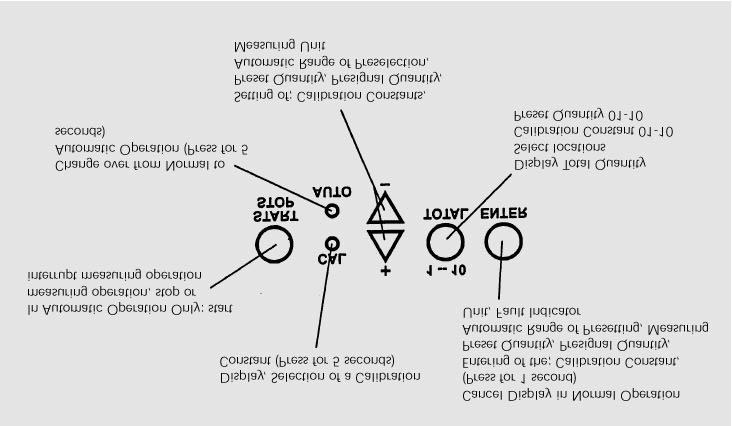
8 LC display view Page 6/18 6. LC display view 7. Meter keys view


9 Operation view Page 7/18 8. Operation view 9. Normal operation mode To perform the following procedures in normal operation mode, refer to - Cancel total quantity (fig. 4) - Display flow rate (fig. 5)


10 Operation Page 8/ Operation Display is flashing; change respective setting by + ; - or The setting will be confirmed by pressing ENTER. 11. Automatic operation mode To perform the following procedures in automatic operation mode, refer to - Cancel total quantity (only possible in normal operation mode) - Display flow rate (fig. 6)


 key 1--10 The display preset quantity will be confirmed")


11 Fill quantity operation Page 9/ Fill quantity operation Automatic operation mode Before pressing the keys At the first press of + or - the display starts flashing After pressing the keys Preset quantity is changed by pressing + or - ; depress for speed input. A change of the preset quantity will reset the cycle counter to 0 A register can be selected by pressing the (TOTAL) key The display preset quantity will be confirmed by pressing the key ENTER. The meter switches automatically over to setting of the presignal quantity. Set precise quantity by + or - A change of the presignal quantity will not reset the cycle counter. The display presignal quantity will be confirmed by pressing the key ENTER. The meter switches automatically over to the preset quantity. Start filling cycle by the key START/STOP Filling cycle: - OFF changes to ON - Cycle counter increases - COUNT is flashing during measuring - Preset quantity is counted to 0 - ON changes to OFF - The leakage quantity is measured for 2 seconds - The set preset quantity is displayed again
12 Fault indicator Page 10/ Fault indicator Fault indicator is flashing! "FFFF" Press the key "Enter" Clear fault Fault The presignal quantity plus the automatically measured leakage quantity are higher than the total filling quantity. Fault indicator is static! "FFFF" Increase total filling quantity or reduce presignal quantity or use higher speed valves (reduce leakage quantity) Press the key "Enter" remaining filling quantity is displayed. Continue measuring operation of the remaining filling quantity by pressing the key "Start/Stop" or No flow has been measured for 5 seconds Press again "Enter" back to the preselection quantity Refill tank or container with liquid Check amplifier, pump and valves for function Rotors do not turn (due to dirt, wear, etc.) Pulse is defective


13 Calibration constant Page 11/ Calibration constant Selection or changes to the calibration constant can be effected in the normal or automatic operation mode. Press CAL for more than 5 seconds Briefly pressing + or - changes the calibration by Depress for speed input. The display constant will be set by pressing the key ENTER. The meter switches automatically back to the previous mode (normal or automatic operation).

14 Select measuring unit Page 12/ Select measuring unit If the measuring unit is changed, all recorded calibration constants will be converted into the new unit. All recorded preset quantities will reset to 0. If the automatic range of presetting is changed, all recorded preset quantities will reset to 0. This mode can be set in normal and automatic operation mode: Press CAL. Then press simultaneously the keys + and -. Keep all three keys pressed for more than 5 seconds. Select the desired measuring unit by pressing the key + and -. The displayed measuring unit will be confirmed by pressing the key ENTER. The meter switches automatically over to the selection of the automatic range of presetting. Select the desired range by pressing the key + or -. The display range will be confirmed by pressing the key ENTER. The meter switches automatically back to the previous mode (normal or automatic operation).
 Outlet to amplifier 2/4 On/Off (main signal) (HS+) Outlet to amplifier")
15 Connections diagram Page 13/ Connections diagram Back view of the LCD electronic: ST2 Connection block 2 2/1 No function 2/2 No function 2/3 Presignal (VS+) Outlet to amplifier 2/4 On/Off (main signal) (HS+) Outlet to amplifier 2/5 No function 2/6 External pulse Input for reed switch (1) Transmission by +3 Volts pulses (ST 2/9) 2/7 External Start/Stop (See example of application 2) 2/8 Minus (GND) 2/9 + 3 Volts reed switch (2) 3 Volt Note: The battery has to be removed when using the extended battery (refer to diagram above).


16 Amplifier diagram Page 14/ Amplifier diagram Amplifier with 1 output 2 amplifiers with 1 output signal Amplifier with 2 output signal for installation into for installation into a switch board. signals for installation into a switch board. a switch board. 18. Example applications Connections and diagrams are typical. Actual installations may vary from those shown in this booklet. Example 1 Electronic display mounted on liquid meter; amplifier with 1 output signal for installation into a switchboard for controlling 1 valve. Refer to fig. 7. Necessary cable connections: A. Control cable from meter to amplifier. B. Voltage cable from amplifier to meter. Example 2 Electronic display mounted on liquid meter; amplifier with 1 output signal for installation into a switchboard for controlling 1 valve; external Start/Stop device. Refer to fig. 8.


17 Example applications Page 15/18 Necessary cable connections: A. Control cable from LC display to amplifier. B. Control cable from external Start/Stop to meter. Supply voltage cable from amplifier to valve. The cable has to be run from PIN 3 to 7 (in this case the presignal cannot be used).
. B. Control cable from quick action tap to amplifier. C. Supply voltage cable from amplifier to valve.")
18 Example applications Page 16/18 Example 3 Electronic display mounted onto quick action tap; amplifier with 1 output signal for installation into a switchboard controlling 1 valve. Liquid meter without display unit. Refer to fig. 9. Necessary cable connections: A. Pulse cable from LC display to quick action tap (max. 12m). B. Control cable from quick action tap to amplifier. C. Supply voltage cable from amplifier to valve.
19 Summary tables Page 17/ Summary tables Summary table for normal operation: If the battery has not been removed within one minute, all registered constants will be reset to Factory calibration on location 01 with calibration fluid Location No. Location No. 01 Factory set (see above) MN4=0089, MN5=0123, MN7=0192, MN10=0278, MN40=0689, MN50=1500 Summary table for automatic operation Presignal Calibration constant 01 to 10 Filling quantity 01 to 10 Location No. Location No. Location No. Location No
20 Warranty Page 18/ Warranty Badger Meter warrants that the products will be free from any defects caused by faulty material or workmanship for a period of twelve (12) months from the date of sale of the products to the enduser (the warranty period ) PROVIDED THAT, during the warranty period: 1. Badger Meter receives notice setting out full details of any defect in any product and details of the time and place of purchase of the product and 2. the enduser returns the product to Badger Meter or its nearest representative at its own costs. Badger Meter shall, as its option, repair or replace the product found defective by its inspection or refund the price paid by the enduser for that product. Badger Meter's liability and the enduser s rights under this warranty shall be limited to such repair, replacement or refund and, in particular, shall not extend to any direct, special, indirect or consequential damage or losses of any nature. Note: This warranty does not form part of, nor does it constitute, a contract between Badger Meter and the enduser. It is additional to any warranty given by the seller of the products and does not exclude, limit, restrict or modify the rights and remedies conferred upon the enduser, or the liabilities imposed on the seller, by any statute or other laws in respect of the sale of the product.
21 Hotline Tel or -31 Fax Badger Meter Europa GmbH Subsidiary of Badger Meter, Inc. Karlstrasse Beuren (Germany)
Intrinsically safe batch controller Batching Master 110i
 Intrinsically safe batch controller Batching Master 110i Installation Guide BVS 04 AT E 172 Revision 12.2 IBS BatchControl GmbH Im Sträßchen 2-4 Tel.: ++49 2441 9199 801 53925 Kall Fax.: ++49 2441 9199
Speaker Selectors Models SSW-L4 EX and SSW-L6 EX. User Manual. SSW-L4 EX (bottom) and SSW-L6 EX (top)
 and SSW-L6 EX (top)") Speaker Selectors Models SSW-L4 EX and SSW-L6 EX User Manual SSW-L4 EX (bottom) and SSW-L6 EX (top) Table of Contents Important Safety Precautions...2 What s Included...2 Introduction... 3 Front Panel...
Speaker Selectors Models SSW-L4 EX and SSW-L6 EX User Manual SSW-L4 EX (bottom) and SSW-L6 EX (top) Table of Contents Important Safety Precautions...2 What s Included...2 Introduction... 3 Front Panel...
Models VSP12824V & VSP12860V
 Programmable Voltage Interface Unit Models VSP12824V & VSP12860V Installation & Programming Manual PREFACE Important Installation Information It is the purchasers responsibility to determine the suitability
Badger Meter Europa GmbH. LMS Baby System. Oil management system USER MANUAL. May Firmware v v3.9. LMS_Baby System_BA_02_1005
 Badger Meter Europa GmbH LMS Baby System Oil management system USER MANUAL May 2010 Firmware v2.21 - v3.9 bcccc Contents Page 1. Basic safety recommendations... 1 2. General description... 2 2.1 Technical
Installation Manual. Flow Max 110
 Installation Manual Flow Max 110 OPERATION Turn on Console by depressing ON. NOTE: This Console is equipped with a Power Down feature. The Power Down feature turns OFF the Console if no flow is sensed
Sonic Ruptor 400. User Manual
 Sonic Ruptor 400 User Manual Data herein has been verified and validated. It is believed adequate for the intended use of the instrument. If the instrument or procedures are used for purposes over and
MOD. KBC HEAD KONTAX BATCH CONTROLLER
 MOD. KBC HEAD KONTAX BATCH CONTROLLER THE INSTRUMENT DESCRIBED IN THIS MANUAL COMPLIES WITH STANDARDS EMC LIKE ESTABLISHED FROM DIRECTIVE THE EEC AND THE 89/336 DIRECTIVE LOW TENSION THE EEC 73/23 2/2/27
PTB 01 ATEX 2064 U, IECEx PTB U. Example / Beispiel / Exemple: Type Operating Instructions
 , Equipment protection fuse with Ex mb II C Gb approval Geräteschutzsicherung mit Zulassung Ex mb II C Gb Fusible de protection d appareil avec homologation Ex mb II C Gb Example / Beispiel / Exemple:
ODYS Xound Mini - 1 -
 V1.0 Important Safety Instructions 1) Read these instructions. 2) Keep these instructions. 3) Heed all warnings. 4) Follow all instructions. 5) Do not use this apparatus near water. 6) Clean only with
Model 8702 DP-CALC Micromanometer
 Ventilation Testing/Balancing Model 8702 DP-CALC Micromanometer Operation and Service Manual 1980260, Revision F July 2006 Model 8702 DP-CALC Micromanometer Operation and Service Manual 1980260, Revision
MODEL 245 / 345 High Range
 MODEL 245 / 345 High Range PRESSURE TRANSMITTER INSTALLATION DATA MANUAL 199 Fire Tower Drive Tonawanda, NY 14150 Toll Free: 1-800-688-0030 International: 716-629-3800 Fax: 716-693-9162 www.viatran.com
Q09 Display Owner s Manual
 Q09 Display Owner s Manual Q09 Display (Shown on 1 inch NPT QSE Meter) 03/2018 TABLE OF CONTENTS INTRODUCTION... 1 IMPORTANT NOTICE... 2 SAFETY... 2 INSTALLATION... 2 OPERATION... 4 Display... 4 Batch
UÊ, Ê* - 1 Ê Ê Ê " /",Ê
 Instruction Manual VDV Distance Meter VDV501-089 ENGLISH Español pg. 6 Français pg. 12 User RG-6 Cat3 RG-11 Cat5e RG-59 Cat6 Short ft m Voltage! pf/ READY www.kleintools.com ENGLISH VDV Distance Meter
MODEL 245 / 345 DigiComp
 MODEL 245 / 345 DigiComp PRESSURE TRANSMITTER INSTALLATION DATA MANUAL 3829 Forest Parkway, Suite 500 Wheatfield, NY 14120 Toll Free: 1-800-688-0030 International: 716-629-3800 Fax: 716-693-9162 www.viatran.com
VELOCICALC Air Velocity Meter
 ENERGY AND COMFORT Ventilation Testing VELOCICALC Air Velocity Meter Model 9525 Operation and Service Manual Copyright TSI Incorporated / May 2007 / All rights reserved. Address TSI Incorporated / 500
Model P4017 Single Channel USB Oscilloscope. Quick Start Guide
 Model P4017 Single Channel USB Oscilloscope Quick Start Guide General Warranty BNC warrants that the product will be free from defects in materials and workmanship for 3 years from the date of purchase
EXTENDER DIGITAL-ANALOG AUDIO. pulseaudio1.com vanco1.com DIGITAL AND ANALOG AUDIO EXTENSION OVER A SINGLE CAT5E/6 CABLE
 DIGITAL-ANALOG AUDIO EXTENDER PART NUMBER PA-EXTDA DIGITAL AND ANALOG AUDIO EXTENSION OVER A SINGLE CAT5E/6 CABLE pulseaudio1.com vanco1.com 800.626.6445 DEAR CUSTOMER Thank you for purchasing this product.
POWER SERIES Plus Watt-VAR / Watt-Power Factor Digital Switchboard Meter User s Manual IM2492WVPF-1
 POWER SERIES Plus Watt-VAR / Watt-Power Factor Digital Switchboard Meter User s Manual General Description The POWER SERIES Plus digital switchboard meters incorporate the latest DSP microprocessor technology.
VDI Pro Voltage & Dry Contact Interface Installation and programming Guide MODEL VDI MK2
 VDI Pro Voltage & Dry Contact Interface Installation and programming Guide MODEL VDI MK2 1 of 18 PREFACE Important Installation Information It is the purchasers responsibility to determine the suitability
CQM1 I/O Terminal Block Conversion Adapter. Easy and secure replacement by reusing the I/O terminal block wiring.
 CQM1 I/O CSM_CJ1W-AT4 DS_E_1_1 Easy and secure replacement by reusing the I/O terminal block wiring You can replace CQM1(H) Series with CJ Series, efficiently using your assets. Time for wiring works and
DuoFern Multiple Wall Controller
 DuoFern Multiple Wall Controller 9494-1 Instruction manual for the electrical connection and for commissioning Item no. 3250 19 74 / Type: 9494-1 (surface-mounted with battery) VBD 663-2 (12.16) Dear Customer,
Installation Instructions
 LUCCI Slim Line Fan Remote Control SKU# 210012 Rated Voltage 220-240V~ 50Hz Thank you for purchasing this quality Lucci product. To ensure correct function and safety, please read and follow all instructions
T100&JY15-12 Series Variable Speed Peristaltic Pump Operating Manual
 T100&JY15-12 Series Variable Speed Peristaltic Pump Operating Manual 2013-6 Contents 1 General Information... 1 1.1 Precaution... 1 1.2 Warranty and Service... 1 1.2.1 Warranty Service... 1 1.2.2 Maintenance
VK-3iX WARRANTY REGISTRATION FORM
 VK-3iX WARRANTY REGISTRATION FORM Unit Serial Number: Customer Name: Address: Date of Purchase: Purchased From: Dealer Name: Address: IMPORTANT NOTE: In order to receive the full five year product warranty,
Model 8732 IAQ-CALC TM Indoor Air Quality Meter
 Indoor Air Quality Model 8732 IAQ-CALC TM Indoor Air Quality Meter Operation and Service Manual 1980393, Revision D October 2004 Model 8732 IAQ-CALC TM Indoor Air Quality Meter Operation and Service Manual
The Next-generation Sensor Networking Units That Revolutionize the Workplace from Introduction and Startup though Operation. Fiber Units.
 Sensor Communications Unit CSM DS_E_1_1 The Next-generation Sensor Networking Units That Revolutionize the Workplace from Introduction and Startup though Operation Low initial cost achieved by distributed
MODEL ATV 4/6 BATTERY POWERED DIGITAL VACUUM INSTRUMENT
 MODEL ATV 4/6 BATTERY POWERED DIGITAL VACUUM INSTRUMENT Contains Operating and Programming Information Model ATV 4/6 Battery Powered Digital Vacuum Instrument ã 1996, Teledyne Electronic Technologies,
Name No. of I/O points Model Safety inputs: 12, test outputs: 4
 Safety I/O s DST1 Series CSM_DST1 Series_DS_E_7_3 Distributed Safety s That Reduce Wiring. Lineup includes four models to accommodate various I/O types and number of I/O points. Monitor the safety system
Operator s Manual Fault Finder and Fault Finder / Remote
 Operator s Manual Fault Finder and Fault Finder / Remote WaRRanty InstRuctIOns LIMITED WARRANTY - A Fault Finder or Fault Finder / Remote Warranty is provided to the original purchaser for a period of
Product Documentation
 Product Documentation Emanate PowerPath TM TempTag PPT-300 Date: April 12, 2016 Document Number: PPT200-001 R1.4 Emanate Wireless, Inc. 11145 Windsor Rd. Ijamsville, MD 21754 Telephone: 844-EMANATE Email:
Speaker Selectors Models SSW-4 and SSW-6. User Manual
 Speaker Selectors Models SSW-4 and SSW-6 User Manual (SSW-4) (SSW-6) Table of Contents Important Safety Precautions... 2 What s Included... 2 Introduction... 3 Front Panel... 3 Rear Panel... 3 Typical
2 CHANNEL, CLASS D AMPLIFIERS PA2X25 PA2X60 PA2X125 PA2X150. pulseaudio1.com vanco1.com
 2 CHANNEL, CLASS D AMPLIFIERS PA2X25 PA2X60 PA2X125 PA2X150 pulseaudio1.com vanco1.com 800.626.6445 DEAR CUSTOMER Thank you for purchasing this product. For optimum performance and safety, please read
Operating Instructions
 Model No.: HDIP01_02 Operating Instructions Thanks for purchasing our product. Please be sure to read this instruction manual Carefully before using our product. Introduction The HDMI-IP Extender allows
Continuous Wave Single Frequency Lasers. Concerto Series. 442nm 25, 50, 75 & 100mW
 User Manual Continuous Wave Single Frequency Lasers Concerto Series 442nm 25, 50, 75 & 100mW Copyright 2012, KLASTECH GmbH. All rights reserved. Information presented herein is believed to be accurate
PRO Owner's Manual
 PRO 3600 Owner's Manual Feature Overview The Pro 3600 operates normally in a standard reference mode where level is displayed as 0.00. However, a new reference point for 0.00 can easily be established
Before starting the system, please carefully read this manual and keep it safely for future reference.
 800-663-3412 Leading Manufacturer of Heavy Duty Engineered Technical Furniture Motor-Control f o r M a x F l e x S e r i e s Before starting the system, please carefully read this manual and keep it safely
DIGITAL VOLTAGE INDICATOR
 DIGITAL VOLTAGE INDICATOR Instruction Manual US Patent 6,998,832 HD ELECTRIC COMPANY 1475 LAKESIDE DRIVE WAUKEGAN, ILLINOIS 60085 U.S.A. PHONE 847.473.4980 FAX 847.473.4981 website: www.hdelectriccompany.com
User's Guide. Model High Precision Quad Output DC Power Supply
 User's Guide Model 382270 High Precision Quad Output DC Power Supply Introduction Congratulations on your purchase of the Extech 382270 DC Power Supply. The Model 382270 can be used for many applications
Solid-state Timer H3FA. Model Number Structure. DIP Model Timer for PC Board Use Provides Contact and Solid-state Output
 Solid-state Timer H3FA Please read and understand this catalog before purchasing the products. Please consult OMRON representative if you have any questions or comments. Refer to Warranty and Application
Series ST. User s Guide DIGITAL TORQUE TOOL TESTERS. .com. Series ST Torque Tool Testers. User s Guide
 Series ST DIGITAL TORQUE TOOL TESTERS.com Mark-10 Corporation has been an innovator in the force and torque measurement fields since 1979. We strive to achieve 100% customer satisfaction through excellence
2/4/6 WAY LED POOL LIGHT CONTROL BOX USER MANUAL
 2/4/6 WAY LED POOL LIGHT CONTROL BOX USER MANUAL USER MANUAL Thank you for choosing the Sunline LED Pool Light Control Box. Before installation, please read this user manual carefully in order to correctly
FA-2448 SIX POSITION Filter Wheel
 15 Discovery Way, Acton, MA 01720 Phone: (978)263-3584, Fax: (978)263-5086 Web Site: www.acton-research.com Operating Instructions Acton Research Corporation FA-2448 SIX POSITION Filter Wheel Rev. 3.05.17
HDMI Extender over Cat5e/6
 Statement Thanks for purchasing this product, please read this user manual carefully before using this product.in the constant effort to improve our product, we reserve the right to make functions or parameters
Conductive Level Controller
 Conductive Level Controller 61F-D21T-V1 Ideal for level control for industrial facilities and equipment. Outputs can be set to self-hold at ON or OFF using self-holding circuits. Sensitivity adjustment
G3NE. Model Number Structure. Solid State Relays. Model Number Legend. Compact, Low-cost, SSR Switching 5 to 20 A
 Solid State Relays CSM DS_E_4_1 Compact, Low-cost, SSR Switching 5 to 20 A Wide load voltage range: 75 to 264 VAC. Both 100-V and 200-V loads can be handled with the same model. Dedicated, compact aluminum
USER S MANUAL ENTITY. Energy Meter TRINITY. Entity Operational Manual
 USER S MANUAL ENTITY Energy Meter This document contains the latest technical information about ENTITY which is a micro-controller based Energy Meter. The unit is tested against latest "MTE" Standard Model
SATA II HDD Canister KISS DA 435 Quick Reference Guide
 SATA II HDD Canister KISS DA 435 Quick Reference Guide If it s embedded, it s Kontron 1. Table of Contents SATA II HDD Canister KISS DA 435 1. Table of Contents 1. Table of Contents... 1 2. Important Information...
PRO 360. Owner's Manual
 One-Year Limited Warranty If, within one year from the date of original purchase, the Pro 360 Digital Protractor fails to function because of defects in materials or workmanship, the manufacturer will,
Model 2460-KIT. Screw Terminal Connector Kit. Description / September 2014 *P * 1
 Keithley Instruments 28775 Aurora Road Cleveland, Ohio 44139 1-800-935-5595 http://www.keithley.com Model 2460-KIT Screw Terminal Connector Kit Description The Model 2460-KIT Screw Terminal Connector Kit
Lotus DX. sit-stand workstation. assembly and operation instructions. MODEL # s: LOTUS-DX-BLK LOTUS-DX-WHT
 Lotus DX assembly and operation instructions sit-stand workstation MODEL # s: LOTUS-DX-BLK LOTUS-DX-WHT safety warnings 13.6 Kg 30 lbs. 2.2 Kg 5 lbs. safety instructions/warning Read and follow all instructions
Installation Instructions
 Lucci Remote Fan Control Non Dimming SKU# 210019 Rated Voltage 240V~ 50Hz Thank you for purchasing this quality Lucci product. To ensure correct function and safety, please read and follow all instructions
DCM Digital Control Modules
 DCM Digital Control Modules TECHNICAL MANUAL Version 1.2 November 2011 Safety Precautions Caution Read Instructions: Read and understand all safety and operating instructions before using the equipment.
E2K-F. Flat Capacitive Sensor with a Thickness of Only 10 mm. Flat Proximity Sensor. Ordering Information. Sensors [Refer to Dimensions on page 4.
 Flat Proximity Sensor EK-F CSM_EK-F_DS_E Flat Capacitive Sensor with a Thickness of Only mm Flat Sensor with excellent space efficiency. (Model with built-in Amplifier is only mm thick.) Direct mounting
OPERATING AND SERVICE MANUAL. Universal Interface Device 47
 OPERATING AND SERVICE MANUAL Universal Interface Device 47 MAGNA-POWER ELECTRONICS, INC. 39 ROYAL ROAD, FLEMINGTON, NJ 08822 May 24, 2012 SAFETY NOTICE Universal Interface Device 47 (UID46) connects
INDOOR/OUTDOOR SPEAKER WITH BLUETOOTH WIRELESS TECHNOLOGY PART NUMBER PA360 EXPERIENCE 360 OF SOUND. pulseaudio1.com vanco1.com
 INDOOR/OUTDOOR SPEAKER WITH BLUETOOTH WIRELESS TECHNOLOGY PART NUMBER PA360 EXPERIENCE 360 OF SOUND pulseaudio1.com vanco1.com 800.626.6445 DEAR CUSTOMER Thank you for purchasing this product. For optimum
Operating Instructions. Intrinsically Safe Isolation Relay for Switches Model: REL manual_rel-6_0505
 Operating Instructions Intrinsically Safe Isolation Relay for Switches Model: REL-6003 manual_rel-6_0505 1. Contents 1. Contents...2 2. Note...3 3. Instrument Inspection...3 4. Regulation Use...3 5. Operating
R & D SPECIALTIES SERIES 100 RO CONTROLLER USERS MANUAL. 2004, by R & D Specialties, Inc. All Rights Reserved.
 R & D SPECIALTIES 2004, by R & D Specialties, Inc. All Rights Reserved. No part of this document may be copied or reproduced in any form or by any means without the prior written permission of R & D Specialties.
PTB 01 ATEX Example / Beispiel / Exemple. Type Operating Instructions
 Device with II 2G EX i approval Geräte mit II 2G EX i Zulassung Appareils avec mode de protection II 2G EX i Example / Beispiel / Exemple Type 6106 Operating Instructions Bedienungsanleitung Manuel d utilisation
INDOOR/OUTDOOR SPEAKER WITH BLUETOOTH WIRELESS TECHNOLOGY PART NUMBER PA360 EXPERIENCE 360 OF SOUND. pulseaudio1.com vanco1.com
 INDOOR/OUTDOOR SPEAKER WITH BLUETOOTH WIRELESS TECHNOLOGY PART NUMBER PA360 EXPERIENCE 360 OF SOUND pulseaudio1.com vanco1.com 800.626.6445 DEAR CUSTOMER Thank you for purchasing this product. For optimum
PMDX-105. I/O Option Riser Board User s Manual. Document Revision: 1.1 Date: 7 September 2004 PCB Revision: PCB-443A
 PMDX-105 I/O Option Riser Board User s Manual Date: 7 September 2004 PMDX Web: http://www.pmdx.com 7432 Alban Station Blvd., A105 Phone: +1 (703) 912-4991 Springfield, VA 22150-2321 USA FAX: +1 (703) 912-5849
G3B/G3BD. Model Number Structure. Ordering Information. Solid State Relays Model Number Legend. List of Models
 Solid State Relays G3@-VD CSM_G3B_G3BD_DS_E_5_1 International Standards for G3B Series, Same Profile as MK Power Relays Shape-compatible with mechanical relays. Certified by UL, CSA, and VDE (models numbers
WA4204-G2/G3 and WA4304-G2/G3
 WA4204-G2/G3 and WA4304-G2/G3 WORKABOUT PRO Multi-Dock User Manual January, 2017 PN 400092-001 2017 Symbol Technologies LLC, a subsidiary of Zebra Technologies Corporation. All Rights Reserved. Return-to-Factory
Exposure Monitoring. Model 8560 INSPECTAIR CO 2. Meter. Operation and Service Manual , Revision B June 2006
 Exposure Monitoring Model 8560 INSPECTAIR CO 2 Meter Operation and Service Manual 1980265, Revision B June 2006 Model 8560 INSPECTAIR CO 2 Meter Operation and Service Manual June 2006 P/N 1980265 Rev.
Table of Contents. 3.1 Front/Rear Panel and User Interface Front Panel Rear Panel User Interface...
 General Warranty OWON warrants that the product will be free from defects in materials and workmanship for a period of 2 years (1 year for accessories) from the date of purchase of the product by the original
BatteryCheck USER MANUAL BATTERY MANAGEMENT TECHNOLOGY THAT POWERS YOUR ADVENTURES.
 BatteryCheck USER MANUAL BM PRO - 19 Henderson Road, Knoxfield 3180, Victoria, Australia Phone +61 3 9763 0962 Fax +61 3 9763 8789 Email sales@teambmpro.com Web www.teambmpro.com BATTERY MANAGEMENT TECHNOLOGY
COOPER POWER SERIES. RS-485 digital communications accessory board installation and operation instructions. Voltage Regulators MN225074EN
 Voltage Regulators MN225074EN Effective March 2017 Supersedes January 2012 (S225-40-7) RS-485 digital communications accessory board installation and operation instructions COOPER POWER SERIES DISCLAIMER
Connecting Sockets, Mounting Brackets, DIN Rails
 Connecting Sockets, Mounting Brackets, DIN Rails CSM_ConnectionSocket_DS_E_3_1 Durable, Easy-to-handle Connecting Sockets and Mounting Brackets Highly reliable Track-mounted and Back-connecting Sockets
DICKSON FH320/325 & FT300/325 DICKSON. Temperature/Humidity Recorder. Specifications. Applications & Product. Product. Contents: Getting Started
 FH320/325 & FT300/325 Temperature/Humidity Recorder Contents: and Instrument Anatomy Accessories Warranty / Accessories, & Calibration FH325 Remote Probe Temperature & Humidity FT325 Remote Probe 2 Channel
Electronic SD1, AS 8, ASR 14, ASR 20
 Electronic SD1, AS 8, ASR 14, ASR 20 2 Electronic SD1, AS 8, ASR 14, ASR 20 Contents Page List of contents..................................................... 3 Function and characteristics.........................
G3FM. Model Number Structure. Ordering Information. Solid State Relays. Model Number Legend. List of Models
 Solid State Relays CSM DS_E_5_3 100-μA-max. Leakage Current, No Bleeder Resistor Required Reduces wiring work by 60% when combined with the PFY-08- PU Push-In Plus Socket (according to actual OMRON measurements).
Temperature & Humidity Datalogger
 R6030 Temperature & Humidity Datalogger Instruction Manual Table of Contents Introduction... 2 Product Quality... 3 Safety... 3 Features... 3 Included... 3 Specifications... 4 Instrument Description...
B2800 FLOW MONITOR. - For Liquid Meters - PROGRAMMING & INSTALLATION MANUAL Simplified Version
 B2800 FLOW MONITOR - For Liquid Meters - PROGRAMMING & INSTALLATION MANUAL Simplified Version 8635 Washington Avenue Racine, Wisconsin 53406 Technical Toll-Free: 877.722.4631 Sales Toll-Free: 800.235.1638
Aton C6. Bedienungsanleitung. User Manual Mode d emploi Istruzioni per l uso
 Aton C6 Bedienungsanleitung User Manual Mode d emploi Istruzioni per l uso CONTENT Getting started.....................................................................3 Safety Precautions................................................................3
CK3W-PD048 CSM_CK3W-PD048_DS_E_DITA_1_2
 CK3W Power Supply Unit CK3W-PD048 CSM_CK3W-PD048_DS_E_DITA_1_2 Supplies power to the CK3M Controller CK3W-PD048 Features 24 VDC input The power supply status indicator shows operating status 1 Ordering
PWRguard PLUS Spring City Drive Waukesha, WI
 PWRguard PLUS www.westmountainradio.com 1020 Spring City Drive Waukesha, WI 53186 262-522-6503 sales@westmountainradio.com 2016, All rights reserved. All trademarks are the property of their respective
COBEX RECORDERS, INC.
 INSTALLATION, OPERATION AND SERVICE INSTRUCTIONS FOR CIRCULAR CHART RECORDERS COBEX RECORDERS, INC. CAUTION: IT IS IMPORTANT THAT THESE INSTRUCTIONS BE READ BEFORE INSTALLING THE INSTRUMENT. KEEP THESE
MIYAWAKI ULTRASONIC TESTER PM11 OPERATOR S MANUAL. Be sure to read this manual for safe and proper operation. Store this manual carefully after use.
 GB MIYAWAKI ULTRASONIC TESTER PM11 OPERATOR S MANUAL Be sure to read this manual for safe and proper operation. Store this manual carefully after use. TABLE OF CONTENTS TO THE OWNER GB-0-2 1. SYMBOL INDICATION
Profibus DP Expansion Board
 Profibus DP Expansion Board Catalog No. EXBD04 Installation and Operating Manual 10/02 MN1393 Table of Contents Section 1 General Information................................................... 1 1 Introduction.......................................................
Series STA DIGITAL TORQUE TOOL TESTERS. User s Guide
 Series STA DIGITAL TORQUE TOOL TESTERS User s Guide Series STA Torque Tool Testers Thank you! Thank you for purchasing a Mark-10 Series STA Digital Torque Tool Tester. We are confident that you will get
AirPro Surveyor 2 Manual
 AirPro Surveyor 2 Manual AirPro Surveyor Specifications Table of Contents Size 3/8 x 7 1/2 x 4 3/8 Weight 4.6 lbs. 2094 g Dynamic Range 1-1000 ml/min. total flow/constant flow Flow Capacity (8 Hrs.) 1000
THECHARGEHUB.COM. User Manual. For Square & Round Models
 THECHARGEHUB.COM User Manual For Square & Round Models User Manual THECHARGEHUB.COM 7-Port USB Universal Charging Station Table of Contents General Safety Information...2 Care and Maintenance...3 Introduction...4
Manual. NanoTron Dual Timer. Installation Maintenance Repair Manual
 Manual NanoTron Dual Timer Installation Maintenance Repair Manual Advantage Controls P.O. Box 1472 Muskogee, OK 74402 Phone: 800-743-7431 Fax: 888-686-6212 www.advantagecontrols.com email: support@advantagecontrols.com
User s Guide. Series CT CLOSURE TORQUE TESTER. User s Guide
 User s Guide Series CT CLOSURE TORQUE TESTER User s Guide Series CT Closure Torque Testers User s Guide Thank you! Thank you for purchasing a Mark-10 Series CT Torque Tester. We are confident that you
DVI Detective. User Manual EXT-DVI-EDIDN. Release A3
 DVI Detective EXT-DVI-EDIDN User Manual Release A3 Important Safety Instructions 1. Read these instructions. 2. Keep these instructions. 3. Heed all warnings. 4. Follow all instructions. 5. Do not use
COOPER POWER SERIES. Input/Output (I/O) module installation instructions. Voltage Regulators MN225067EN
 module installation instructions. Voltage Regulators MN225067EN") Voltage Regulators MN225067EN Effective November 2016 Supersedes June 2014 (S225-70-13) COOPER POWER Input/Output (I/O) module installation instructions SERIES DISCLAIMER OF WARRANTIES AND LIMITATION OF
Voltage Regulators MN225067EN Effective November 2016 Supersedes June 2014 (S225-70-13) COOPER POWER Input/Output (I/O) module installation instructions SERIES DISCLAIMER OF WARRANTIES AND LIMITATION OF
Inductive sensor Dual sensors with extended temperature range NI4-DSU35TC-2Y1X2/S97
 ATEX category II 2 G, Ex zone 1 ATEX category II 1 D, Ex-zone 20 for temperatures up to -25 C SIL2 acc. to IEC 61508 Rectangular, housing DSU35 Plastic, PP-GF30-VO Two outputs for monitoring the position
PDS8u POWER DISTRIBUTION SYSTEM USER'S MANUAL
 PDS8u POWER DISTRIBUTION SYSTEM USER'S MANUAL 1 IMPORTANT SAFETY INSTRUCTION READ FIRST This symbol, whenever it appears, alerts you to the presence of uninsulated dangerous voltage inside the enclosure-voltage
NIMBUS a personal dashboard for your digital life
 INVENTED BY REAL PEOPLE LIKE YOU Ryan Pendleton NIMBUS a personal dashboard for your digital life OVERVIEW Part of the Quirky + GE collection of smart products, Nimbus is a highly customizable 4-dial clock
Quick Start Guide CJB1950ALAAB
 Quick Start Guide 1 CJB1950ALAAB www.sar-tick.com This product meets applicable national SAR limits of 2.0W/kg. The specific maximum SAR values can be found in the section of this user guide. When carrying
Introduction. Package Contents. System Requirements
 VP6230 Page 1 Page 2 Introduction Congratulations on your purchase of the Blu-Link Folding Bluetooth Keyboard. This innovative portable folding keyboard connects via Bluetooth technology to provide a wireless
POWER SERIES Plus. 3 in 1 AC Voltage. Digital Switchboard Meter. User s Manual IM2493VVV-2
 POWER SERIES Plus 3 in 1 AC Voltage Digital Switchboard Meter User s Manual General Description The POWER SERIES Plus digital switchboard meters incorporate the latest DSP microprocessor technology. Careful
WCC100 IN-VEHICLE CHARGING CRADLE OWNER S MANUAL
 WCC100 IN-VEHICLE CHARGING CRADLE OWNER S MANUAL 128-9237B WCC100 In-Vehicle Charging Cradle 12 03 13.indd 1 12/4/2013 10:38:04 AM 128-9237B WCC100 In-Vehicle Charging Cradle 12 03 13.indd 2 12/4/2013
Sensing method Appearance Connection method Sensing distance Model. Pre-wired (2 m) Power supply Application Appearance Function Model
 Power supply Application Appearance Function Model") Small Spot/Mark (Separate Amplifier) EC-VS/VM CSM_EC-VS/VM_DS_E_6_ Extremely thin beam ideal for detection of minute objects and marks Ideal for detection of small objects and slight color differences
Small Spot/Mark (Separate Amplifier) EC-VS/VM CSM_EC-VS/VM_DS_E_6_ Extremely thin beam ideal for detection of minute objects and marks Ideal for detection of small objects and slight color differences
ACL 350 Digital Static Locator
 ACL 350 Digital Static Locator OPERATION MANUAL Meter is warranted for one year from the date of purchase on parts and labor. Calibration is recommended every twelve months. 840 W. 49 th Place Page 1 of
PS8 - II. Professional Power Sequencer. User s Manual
 PS8 - II Professional Power Sequencer User s Manual IMPORTANT SAFETY INSTRUCTIONS READ FIRST This symbol, whenever it appears, alerts you to the presence of uninsulated dangerous voltage inside the enclosure.
Number of input channels
 Safety Relay Unit (Sensor Connector Type) CSM DS_E_3_1 Less Wiring Required with Safety Light Curtain Sensor connector allows direct connection to OMRON 3SJ Safety Light Curtains with PNP outputs. Reduces
Model A7BS
 Thumbwheel Switch ABS/ABL CSM_ABS/ABL_DS_E Wide Range of Locking-type s Available Character height of.8 or. mm makes for easy-toview display. Installation is easy with snap-in mounting. The series includes
NE1A-SCPU Series. Safety Network Controller. Achieve Safety Control through Programming. Ordering Information. Specifications.
 Safety Network Controller NEA-SCPU Series CSM_NEA-SCPU_Series_DS_E Achieve Safety Control through Programming. Compact Safety Controller. The NEA-SCPU-V provides built-in safety inputs and 8 built-in safety
Series CTA CAP TORQUE TESTERS. User s Guide
 Series CTA CAP TORQUE TESTERS User s Guide Series CTA Cap Torque Testers Thank you! Thank you for purchasing a Mark-10 Series CTA Cap Torque Tester. We are confident that you will get many years of service
NJ NJ-series NJ501 SECS/GEM CPU Unit. Allows SECS/GEM communications in a short time with a simple configuration. Feature
 NJ-series NJ501 SECS/GEM CPU Unit NJ501-1340 CSM_NJ501-1340_DS_E_3_1 Allows SECS/GEM communications in a short time with a simple configuration. The NJ501 SECS/GEM CPU Unit is a NJ-series machine automation