ARM programmer and daughter board
|
|
|
- Melina James
- 6 years ago
- Views:
Transcription

1 ARM programmer and daughter board EB185


2 Contents About this document 3 Board layout 3 General information 4 Circuit description 4 Protective cover 5 Circuit diagram 6 2 Copyright

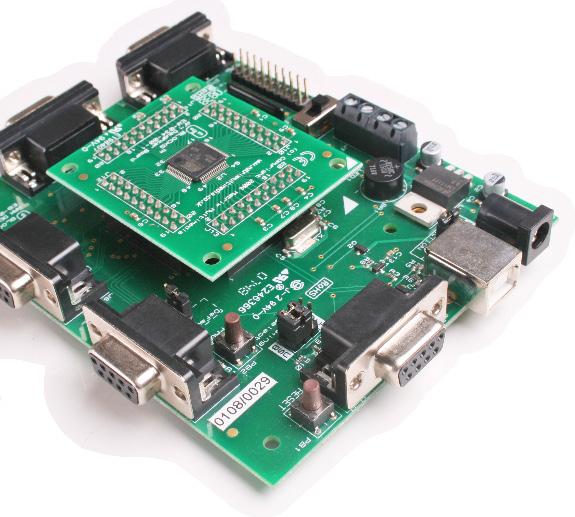
3 About this document This document concerns the EB185 E-blocks ARM programmer and daughter board. 1. Trademarks and copyright PIC and PICmicro are registered trademarks of Arizona Microchip Inc. E-blocks is a trademark of Matrix Technology Solutions Ltd. 2. Disclaimer The information provided within this document is correct at the time of going to press. Matrix TSL reserves the right to change specifications from time to time. 3. Testing this product It is advisable to test the product upon receiving it to ensure it works correctly. Matrix provides test procedures for all E-blocks, which can be found in the Support section of the website. 4. Product support If you require support for this product then please visit the Matrix website, which contains many learning resources for the E-blocks series. On our website you will find: How to get started with E-blocks - if you are new to E-blocks and wish to learn how to use them from the beginning there are resources available to help. Relevant software and hardware that allow you to use your E-blocks product better. Example files and programs. Ways to get technical support for your product, either via the forums or by contacting us directly. Board layout Screw terminals 2. Power connector 3. USB connector 4. Power selector link block 5. Port E I/O 6. Reset switch 7. Port A I/O 8. Port B I/O 9. Port C I/O 10. Port D I/O 11. JTAG interface 12. Power switch 13. ARM daughter board 14. Programming selector link block 15. Programming switch 16. Recovery selector link block Copyright
4 General information This E-block board is a development tool for the powerful AT91 SAM 7 microcontroller from Atmel. The SAM 7 is a 32 bit RISC device running at an interval frequency of 36MHz, and having 128k ROM and 32K static RAM as well as 2 USARTs, 4 x 10 bit A/D converters and a native USB bus. This incredibly powerful microcontroller can be used for a range of advanced E-blocks projects. The board has five E-blocks ports and the processor itself is housed on a removable daughter board (Atmel ARM processors are only available in SMD technology) so that the ARM can be incorporated into custom PCBs. 1. Features 32 bit RISC processor with 128K ROM and 32K SRAM USB programmable with boot loader 5 x E-blocks ports, 32 I/O lines Compatible with most downstream boards Native USB and SPI buses Removable crystal Circuit description The ARM board solution is made up of two parts: A mother board (ARM board EB031) that allows ARM devices to be programmed and the program to be executed seamlessly. The ARM daughter board (EB034) that houses the ARM device on a simple to use board. This allow the user to program the device using the ARM board (EB031) and then either use this daughter board in either the ARM board (EB031) for development, or to easily use the ARM daughter board in another project. 1. Power supply The board is normally operated from an external regulated DC power supply of 6V - 9V. This allows full operation including programming. The board has two modes of power supply; either from an external regulated DC power supply or powered using the computer via the USB port. The external power supply is specified as 6-9V regulated DC power supply. When using the USB port to power the board, the user must be aware of the limitations for the use of this USB port - for example the limited current that can be supplied via USB (approx. 100mA). The jumper link system, J16, allows the user to decide on the source of the power supply. If using an external power supply the jumper should be positioned to the left hand side of the jumper system labelled PSU. If using USB power place the jumper on the right hand 4 side of the jumper system. LED1 indicates that power is supplied to the board from either the external power supply or the USB cable. Please note that both USB and the PSU cables should be removed for the ARM board before changing the position of this jumper. Remember that other E-blocks will have to receive 3.3V by placing a connecting wire from the +V screw terminal of the ARM board to the +V screw terminal of each E-block that requires a voltage. Also the user should ensure that all the E-blocks that they are using are 3.3V compatible. 2. Programming (hardware) The ARM board connects to a personal computer via the USC socket. Any USB socket on the PC can be used. The host ARM device is set-up to communicate with the USB bus and the programming circuitry. The board uses MOSFET transistors to detect the USB bus, which allows the board to be programmed. The board has a connection ( DIL PCB header pins) that allows the ARM device to be programmed via an external programmer using the JTAG pins available on the ARM device. This is a standard JTAG connection. DIL sockets and I/O ports The ARM board uses an external ARM daughter board. This daughter board enables the ARM board to be both a development board and a programmer. This means Copyright
5 that the user can either use the ARM daughter board in the ARM board for development, or for programming the daughter board which can then be used in other projects. The ARM board connects to the ARM daughter board (EB034) via four DIL PCB sockets ( ). These connect all the ARM device signals to the ARM daughter board, thus allowing programming and use of all the functions available on the ARM device. The ARM board has five I/O ports, in the form of 9-way D-type connectors. These allow the ARM board to be fully compatible with the E-blocks range. The first four D-type connectors (J5-8) connect all 32 general-purpose I/O from the ARM device. Most of these general-purpose I/O pins have multiple functions - such features as SPI. USART communication and analogue to digital converters. Please see the datasheet of the actual ARM device that you are using for complete list of functions ( 4. Reset push button PB1 provides a reset by pulling the NRST pin low. This will reset the ARM device thus enabling any program to restart. Please note that the NRST can be programmed so that the reset pin will not function as a reset. See the datasheet for the ARM device that you are using for more details on disabling the NRST as a reset. 5. Frequency selection The clock signal for this board is generated from either an internal RC clock signal or the on-board external crystal. The on-board crystal is set to MHz as this enables the USB synchronisation speed to be correct - as stated by the software specification. The device can also use an internal PLL to set the frequency for the device. Please see the datasheet of the device for further information regarding using the PLL. The ARM device has four dedicated analogue to digital converters and four general-purpose I/O with analogue functionality. Therefore all these either signals have been grouped together, on the fifth D-type connector (J9), which can be used as a fully analogue port. Please note that the four general-purpose I/O are also available on the another D-type connector (J8) and care must be taken to ensure that these signals are not connected to any other device whilst using them on these fully analogue port (J9). A full table of I/O connections is provided on page Programming (software) There are two ways of getting the ARM board into programming mode: With the power to the board on press and hold down the PROG button switch. Then quickly press and release the RESET button switch. If your drivers are set up then you will hear Windows give a double tone to indicate a USB device has been discovered. If you have used D4 or B5 as an output then you may find that the driver gets disassociated. In this case you can use this alternate method: Turn power to the ARM board off using SW 1. Press and hold the PROG button switch down. Turn power on with SW1, and less than half a second after release the PROG button switch. 5 Copyright

6 Re-flashing the ARM board 1. When to re-flash Re-flashing is only required if the Matrix ARM OS has been deleted or overwritten, or if an updated Matrix OS file has been released. Re-flashing should only be carried out when specifically required as errors and complications may cause the ARM board to stop functioning until properly re-flashed. In our experience the device can need re-flashing if you reset the ARM half way through a programming cycle to prevent this please ensure that you give the PC sufficient time to download your program. The symptoms here are that the ARM board appears to be dead and a PROG button with RESET button activation does not work, and 2 neither does a power up PROG button activation work. General programming is performed without requiring re-flashing. Please refer to the mloader documentation for general programming instructions. If the ARM is a new device it may require the default ARM drivers. These drivers are installed by SAM-BA. Please install SAM-BA before installing the USB drivers for the ARM board. 2. Required items: SAM-BA ARM re-flash software. Available on ELSAM 2.0 or later and from ATMEL ( Re-flash programs (ARM_MM.bin and test.bin) 3. Set-up The ARM board requires re-flashing to put the Matrix ARM OS onto the ARM board. 1. Re-flashing can be done with USB power only. 2. Check J16 power selector set to USB. 3. Check J18 programming jumper set to USB. 4. Check J15 TST jumper set to Default. 5. Plug the board into the PC and turn the power switch SW1 to ON. 6. Check that the Green Power LED is lit. 2. Move SW1 to OFF and replace the TST jumper to the Default position. 3. Move SW1 to ON. 4. Open SAM-BA. 5. Find the USB board in SAM-BA. Select - AT91SAM7S128-EK and click on USB connection. A programming dialogue should not appear. 6. In the middle of the dialogue are the Browse button (1) to locate files, the memory address location (2), and the Send button Send the test file: Browse to (1) and open file test.bin in the C:\ program files \ Matrix Technology Solutions \ mloader \ Reflasher files folder. Set the memory location (2) to 0x Send the file. Select OK to any Unlock zone / regions messages. 8. Send the main file: Browse to (1) and open file ARM-MM.bin in the C:\ program files \ Matrix Technology Solutions \ mloader \ Reflasher files folder. Set the memory location (2) to 0x Send the file Select OK to any Unlock zone messages. 9. Move SW1 to OFF. 10. Add LED boards. 11. Move SW1 to ON. 12. The LEDs should now be showing alternate pairs creating a to pattern. The ARM board should now be ready for testing Re-flashing process 1. Place the TST jumper (J15) to test position - i.e. the bottom pins, straddling the Default box border. Leave for at least 8-10 seconds. 6 Copyright
7 Port and pin list E-blocks ports ARM pin name ARM pin Notes A0 PA0 48 A1 PA1 47 A2 PA2 44 A3 PA3 43 A4 PA4 36 A5 PA5 35 A6 PA6 34 A7 PA7 32 B0 PA8 31 B1 PA9 30 B2 PA10 29 B3 PA11 28 B4 PA12 27 B5 PA13 22 USB Pin B6 PA14 21 B7 PA15 20 C0 PA24/RTS1 23 C1 PA26 26 C2 PA27 37 C3 PA28 38 C4 PA25/CTS1 25 C5 PA23 15 C6 PA22/TXD1 14 C7 PA21/RXD1 11 D0 PA17/AD0 9 Also on E0 - Analogue Pin D1 PA18/AD1 10 Also on E1 - Analogue Pin D2 PA19/AD2 13 Also on E2 - Analogue Pin D3 PA20/AD3 16 Also on E3 - Analogue Pin D4 PA16 19 USB Pin D5 PA29 41 D6 PA30 42 D7 PA31 52 E0 PA17/AD0 9 Also on D0 - Analogue Pin E1 PA18/AD1 10 Also on D1 - Analogue Pin E2 PA19/AD2 13 Also on D2 - Analogue Pin E3 PA20/AD3 16 Also on D3 - Analogue Pin E4 AD4 3 Analogue Pin E5 AD5 4 Analogue Pin E6 AD6 5 Analogue Pin E7 AD7 6 Analogue Pin 1. Notes The ARM has a 32 bit I/O register and 8 analogue input lines On the E-blocks ARM board the 32 bit register has been broken down into four ports - Ports A, B, C and D. The pin to port allocation does not correspond directly 0-31 with Ports A-D due to the need to place serial communications pins on the same port (Port C). Please refer to the table on the left when working with the 32 bit I/O register. Four of the analogue lines use pins in the 32 bit digital I/O port. Four of the analogue lines are separate only lists. Port E contains the 8 analogue input lines. This means that Port E pins E0-E3 duplicate those of Port D pins D0-D3. Pins E4-E7 are analogue lines only, not general I/O. Pins B5 and D4 are used in USB communications. Signals on these lines may affect the USB bus causing erroneous activations of the USB New device added wizard. To prevent this either do not use Pins B5 and D4, or move the Programming Pin Select jumper (J18) to the I/O position whilst running the program (move it back to USB for programming). 7 Copyright


8 Protective cover Most of the boards in the E-blocks range can be fitted with a plastic cover as an optional extra. These covers are there to protect your E-blocks board therefore extending the life of the board. The covers also prevent the removal of external components while still allowing for the adjustment of applicable parts on the board. 12mm M3 spacers, anti-slip M3 nuts and 25mm M3 bolts can be used to attached the cover to the board. These are not included but can be bought separately from our website. The order code for the EB003 multimedia board is EB Copyright
9 Circuit diagram 9 Copyright
10 Circuit diagram 10 Copyright
11 Circuit diagram 11 Copyright


12 Matrix Technology Solutions Ltd. The Factory 33 Gibbet Street Halifax, HX1 5BA, UK t: +44 (0) e: EB
ARM programmer and daughter board EB Technical datasheet
 ARM programmer and daughter board EB185-00-1 Technical datasheet Contents 1 About this document...2 2 General information...3 3 Description...3 4 Board layout...4 5 Testing this product...5 6 Circuit description...7
Sensor board. EB003
 Sensor board www.matrixtsl.com EB003 Contents About this document 3 Board layout 3 General information 4 Circuit description 4 Protective cover 5 Circuit diagram 6 2 Copyright About this document This
Power board. EB011
 Power board www.matrixtsl.com EB011 Contents About this document Board layout General information Circuit description Protective cover Circuit diagram 2 3 3 5 5 6 Copyright Matrix Technology Solutions
Opto-isolator board. EB035
 Opto-isolator board www.matrixtsl.com EB035 Contents About this document Board layout General information Circuit description Protective cover Circuit diagram 2 3 3 4 4 5 5 Copyright Matrix Technology
Motor angle (servo) trainer board
 trainer board") Motor angle (servo) trainer board www.matrixtsl.com EB097 Contents About this document Board layout General information Protective cover Circuit description Circuit diagram 2 3 3 5 Copyright Matrix Technology
Motor angle (servo) trainer board www.matrixtsl.com EB097 Contents About this document Board layout General information Protective cover Circuit description Circuit diagram 2 3 3 5 Copyright Matrix Technology
VGA multimedia board
 VGA multimedia board www.matrixtsl.com EB071 Contents About this document 3 Board layout 3 General information 4 Circuit description 5 Protective cover 5 Circuit diagram 6 2 Copyright About this document
CPLD board. EB020
 CPLD board www.matrixtsl.com EB020 Contents About this document Board layout General information Circuit description Protective cover Circuit diagram 2 4 5 7 Copyright About this document This document
TFT LCD multimedia board with touchscreen
 TFT LCD multimedia board with touchscreen www.matrixtsl.com EB076-LCD32T Contents About this document 3 Board layout 3 General information 4 Circuit description 5 Circuit diagram 6 2 Copyright About this
USB232 board. EB039
 USB232 board www.matrixtsl.com EB039 Contents About this document 3 Board layout 3 General information 4 Circuit description 4 Protective cover 5 Circuit diagram 6 2 Copyright About this document This
Wireless LAN board. EB069
 Wireless LAN board www.matrixmultimedia.com EB069 Contents About this document 3 Board layout 3 General information 4 Protective cover 4 Testing the product 5 Circuit description 6 Circuit diagram 7 2
OLED graphical LCD board
 OLED graphical LCD board www.matrixtsl.com EB057 EB058 Contents About this document Board layout General information Circuit description Protective cover Circuit diagram 2 4 4 5 6 Copyright Matrix Technology
LCD board. EB005
 LCD board www.matrixtsl.com EB005 Contents About this document 3 Board layout 3 General information 4 Circuit description 6 Protective cover 6 Circuit diagram 7 2 Copyright About this document This document
LED board. EB004
 LED board www.matrixmultimedia.com EB004 Contents About this document 3 Board layout 3 General information 4 Circuit description 4 Protective cover 4 Circuit diagram 5 2 Copyright About this document This
ECIO base board. EB061
 ECIO base board www.matrixmultimedia.com EB061 Contents About this document 3 Board layout 3 General information 4 Circuit description 4 Circuit diagram 5 2 Copyright Matrix Multimedia Ltd. About this
SPI memory and D/A board
 SPI memory and D/A board www.matrixtsl.com EB013 Contents About this document 3 Board layout 3 General information 4 Circuit description 4 Protective cover 6 Circuit diagram 7 2 Copyright About this document
Wireless LAN board. EB069
 Wireless LAN board www.matrixmultimedia.com EB069 Contents About this document 3 Board layout 3 General information 4 Circuit description 4 Protective cover 5 Circuit diagram 6 2 Copyright Matrix Multimedia
PS/2 and SVGA board. EB033
 PS/ and SVGA board www.matrixtsl.com EB033 Contents About this document 3 Board layout 3 General information 4 Circuit description 4 Circuit diagram 6 Copyright About this document This document concerns
Accelerometer board. EB068
 Accelerometer board www.matrixtsl.com EB0 Contents About this document Board layout General information Testing this product Circuit description 5 Circuit diagram Copyright 0 Matrix TSL About this document
TFT Graphical LCD Board
 TFT Graphical LCD Board www.matrixtsl.com EB084 Contents About This Document 2 General Information 3 Board Layout 4 Testing This Product 5 Circuit Description 6 Circuit Diagram EB084 7 Circuit Diagram
IR/IrDA transceiver board
 IR/IrDA transceiver board www.matrixtsl.com EB01 Contents About this document 3 Board layout 3 General information 4 Circuit description 5 Protective cover 7 Circuit diagram 8 Copyright About this document
Raspberry Pi board. EB080
 Raspberry Pi board www.matrixmultimedia.com EB080 Contents About this document 3 Board layout 3 General information 4 Circuit description 4 Circuit diagram 5 2 Copyright Matrix Multimedia Ltd. About this
Atmel AVR datasheet. Matrix Multimedia Atmel AVR Board EB Contents
 Atmel AVR datasheet Contents 1. About this document 2. General information 3. Board overview 4. Getting Started 5. Block schematic and description Appendix A. Circuit diagram B. Compatible AVR device C.
1. About this document General information Board layout Testing this product Circuit description...
 dspic / PIC24 Multiprogrammer datasheet EB064-00 00-1 Contents 1. About this document... 2 2. General information... 3 3. Board layout... 4 4. Testing this product... 5 5. Circuit description... 6 Appendix
CPLD board datasheet EB
 CPLD board datasheet EB020-00-3 Contents. About this document... 2 2. General information... 3 3. Board layout... 4 4. Testing this product... 5 5. Circuit description... 6 Appendix Circuit diagram Copyright
CPLD board datasheet EB
 CPLD board datasheet EB020-00- Contents. About this document... 2 2. General information... 3 3. Board layout... 4 4. Testing this product... 5 5. Circuit description... 6 Appendix Circuit diagram Copyright
ECIO Base Board datasheet EB061-00
 ECIO Base Board datasheet EB061-00 00-2 Contents 1. About this document... 2 2. General information... 3 3. Board layout... 4 4. Circuit description... 5 Appendix 1 Circuit diagram Copyright Matrix Multimedia
PICmicro Microcontroller Lite programmer datasheet
 PICmicro Microcontroller Lite programmer datasheet Contents 1. About this document 2. General information 3. Board overview 4. Getting Started 5. Block schematic and description Appendix A. Circuit diagram
PICmicro MCU multiprogrammer
 PICmicro MCU multiprogrammer www.matrixtsl.com EB006V9 Contents About this document General information Board layout Circuit description Protective cover PICmicro microcontroller pin out details Bus connections
LIN bus board datasheet EB
 LIN bus board datasheet EB027-00-1 Contents 1. About this document... 2 2. General information... 3 3. Board layout... 4 4. Testing this product... 5 5. Circuit description... 7 Appendix 1 Circuit diagram
Card Reader Board EB037-00
 Card Reader Board EB037-00 00-1 Contents 1. About this document... 2 2. General information... 3 3. Board layout... 4 4. Testing this product... 5 5. Circuit description... 6 Appendix 1 Circuit diagram
eblocks A Adaptor Board datasheet Matrix Multimedia Adaptor Board Contents
 Adaptor Board datasheet version 2 board adaptor D E eblocks A C B Contents 1. About this document 2. General information 3. Board Layout 4. Getting Started 5. Circuit description Appendix o Circuit Diagram
SPI Memory and D/A board datasheet EB
 SPI Memory and D/A board datasheet EB013-00-2 Contents 1. About this document...2 2. General information...3 3. Board layout...4 4. Testing this product...5 5. Circuit description...6 Appendix 1 Circuit
Opto-isolator board datasheet EB
 Opto-isolator board datasheet EB-035-00-1 CONTENTS 1. About this document 2 2. General Information 3 3. Board layout. 4 4. Testing this product... 4 5. Circuit description. 5 Appendix 1 Circuit diagram
Motor driver board. EB022
 Motor driver board www.matrixmultimedia.com EB022 Contents About this document 3 Board layout 3 General information 4 Circuit description 5 Circuit diagram 6 2 Copyright About this document This document
RS485 board datasheet EB062-00
 RS485 board datasheet EB062-00 00-1 Contents 1. About this document... 2 2. General information... 3 3. Board layout... 4 4. Testing this product... 5 5. Circuit description... 6 Appendix 1 Circuit diagram
Home Automation Board datasheet
 Home Automation Board datasheet Contents 1. About this document 2. General information 3. Board Layout 4. Getting Started 5. Circuit Description Appendix 1 Circuit Diagram Copyright 2004 Matrix Multimedia
Internet board datasheet EB
 Internet board datasheet EB023-00-1 Contents 1. About this document... 2 2. General information... 3 3. Board layout... 4 4. Testing this product... 5 5. Circuit description... 9 Appendix 1 Circuit diagram
USB232 board EB Technical datasheet
 USB232 board EB039-00-1 Technical datasheet Contents 1. About this document...2 2. General information...3 3. Board layout...4 4. Testing this product...5 5. Circuit description...7 Appendix 1 Circuit
4D Picaso Touchscreen Display board datasheet EB
 4D Picaso Touchscreen Display board datasheet EB076-00 00-1 CONTENTS 1. About this document. 2 2. General Information.. 3 3. Board layout... 3 4. Testing this product... 4 5. Circuit description.. 4 Appendix
Bluetooth board EB Technical datasheet
 Bluetooth board EB024-00-2 Technical datasheet Contents 1. About this document... 2 2. General information... 3 3. Board layout... 4 4. Testing this product... 5 5. Circuit description... 7 Appendix 1
Locktronics PICmicro getting started guide
 Page 2 getting started guide What you need to follow this course 2 Using the built-in programs 3 Create your own programs 4 Using Flowcode - your first program 5 A second program 7 A third program 8 Other
Graphical LCD Display Datasheet EB
 Graphical LCD Display Datasheet EB043-00-1 Contents 1. About this document... 2 2. General information... 3 3. Board layout... 6 4. Testing this product... 7 5. Circuit description... 8 Appendix 1 Circuit
M32 Development Board
 M32 Development Board User Guide Document Control Information This Document Release Date: 12th March 2006 This Document Version: 1.0 Document History Author Release Date Reference Release Notes JSL 23rd
FPGA starter pack. EB940
 FPGA starter pack EB940 General information This starter pack is a flexible training solution for learning FPGA and CPLD programming and for project work. 1. Benefits A complete learning solution including
SBAT90USB162 Atmel. SBAT90USB162 Development Board User s Manual
 SBAT90USB162 Atmel AT90USB162 Development Board User s manual 1 1. INTRODUCTION Thank you for choosing the SBAT90USB162 Atmel AT90USB162 development board. This board is designed to give a quick and cost-effective
Dwarf Boards. DB057 : 40-pin controller board
 Dwarf Boards DB057 : 40-pin controller board PICmicro, In-Circuit Serial Programming and ICSP are registered trademarks of Microchip Technology Inc. DB057 for USB PIC DB057 for non-usb PIC Introduction
AKKON USB CONTROLLER BOARD
 TN002 AKKON USB CONTROLLER BOARD USB Microcontroller board with the PIC18F4550 * Datasheet Authors: Gerhard Burger Version: 1.0 Last update: 20.01.2006 File: Attachments: no attachments Table of versions
ARDUINO M0 PRO Code: A000111
 ARDUINO M0 PRO Code: A000111 The Arduino M0 Pro is an Arduino M0 with a step by step debugger With the new Arduino M0 Pro board, the more creative individual will have the potential to create one s most
Bolt 18F2550 System Hardware Manual
 1 Bolt 18F2550 System Hardware Manual Index : 1. Overview 2. Technical specifications 3. Definition of pins in 18F2550 4. Block diagram 5. FLASH memory Bootloader programmer 6. Digital ports 6.1 Leds and
DSP Audio Training Solution
 DSP Audio Training Solution Now compatible with EB650 General information This solution provides a motivating solution for learning about digital signal processing (DSP) technology, audio effects and frequency
SBR The Chameleon Converter II
 SBR 0981 The Chameleon Converter II Security Engineering 2003-2015 The Chameleon converter II: Concept: The Chameleon converter II is a one-fits-all protocol conversion PCB that is designed to host one
Getting Started with STK200 Dragon
 Getting Started with STK200 Dragon Introduction This guide is designed to get you up and running with main software and hardware. As you work through it, there could be lots of details you do not understand,
IrDA Board datasheet. Matrix Multimedia IrDA Board. Contents
 IrDA Board datasheet Contents 1. About this document 2. General information 3. Board Layout 4. Getting Started 5. Circuit Description Appendix 1 Circuit Diagram Copyright 2004 Matrix Multimedia Limited
Combined Serial and Parallel Programming System for Atmel AVR Microcontrollers AVR2-ST GETTING STARTED
 Combined Serial and Parallel Programming System for Atmel AVR Microcontrollers AVR2-ST GETTING STARTED (Revision 1.03) Copyright Information Equinox guarantees that its products will be free from defects
LBAT90USB162 Atmel. LBAT90USB162 Development Board User s Manual
 LBAT90USB162 Atmel AT90USB162 Development Board User s manual 1 1. INTRODUCTION Thank you for choosing the LBAT90USB162 Atmel AT90USB162 development board. This board is designed to give quick and cost-effective
StrongARM** SA-110/21285 Evaluation Board
 StrongARM** SA-110/21285 Evaluation Board Brief Datasheet Product Features Intel offers a StrongARM** SA-110/21285 Evaluation Board (EBSA-285) that provides a flexible hardware environment to help manufacturers
EB-51 Low-Cost Emulator
 EB-51 Low-Cost Emulator Development Tool for 80C51 Microcontrollers FEATURES Emulates 80C51 Microcontrollers and Derivatives Real-Time Operation up to 40 MHz 3.3V or 5V Voltage Operation Source-Level Debugger
Getting Started Guide
 Introduction Flowcode is an Integrated Development Environment (IDE) for programming microcontrollers such as 8, 16 and 32bit PIC, Arduino and ARM devices. It achieves this by using flowcharts instead
XNUCLEO-F030R8, Improved STM32 NUCLEO Board
 XNUCLEO-F030R8, Improved STM32 NUCLEO Board STM32 Development Board, Supports Arduino, Compatible with NUCLEO-F030R8 XNUCLEO-F030R8 Features Compatible with NUCLEO-F030R8, onboard Cortex-M0 microcontroller
Sensor Board datasheet
 Sensor Board datasheet Contents 1. About this document 2. General information 3. Board Layout 4. Getting Started 5. Circuit description Appendix 1 Circuit Diagram 2 Sensors Copyright 2005 Matrix Multimedia
Zigbee training solution
 Zigbee training solution Now compatible with EB284 General information Zigbee provides a motivating solution for learn-ing about Zigbee wireless area network communications technology, system construction,
Figure 1-1 ISPAVRU1 application
 ISP AVR Programmer through USB Main Features AVR Studio Interface (AVR Studio 4.12 or later) Supports all AVR Device with ISP interface, refer to AVR Studio Programs both Flash and EEPROM Supports Fuse
Arduino Uno. Arduino Uno R3 Front. Arduino Uno R2 Front
 Arduino Uno Arduino Uno R3 Front Arduino Uno R2 Front Arduino Uno SMD Arduino Uno R3 Back Arduino Uno Front Arduino Uno Back Overview The Arduino Uno is a microcontroller board based on the ATmega328 (datasheet).
2214 EVENT LOGGER MODULE FOR THE VX2200 SYSTEM
 2214 EVENT LOGGER MODULE FOR THE VX2200 SYSTEM CONTENTS PAGE Manual Introduction 3 Product Overview 3 Operation and Connection 3 RS232 Connection 3-4 RS485 Connection 3-4 2214 PCB layout 5 RS485 Bus Terminal
8051 Intermidiate Development Board. Product Manual. Contents. 1) Overview 2) Features 3) Using the board 4) Troubleshooting and getting help
 Overview 2) Features 3) Using the board 4) Troubleshooting and getting help") 8051 Intermidiate Development Board Product Manual Contents 1) Overview 2) Features 3) Using the board 4) Troubleshooting and getting help 1. Overview 2. Features The board is built on a high quality FR-4(1.6
8051 Intermidiate Development Board Product Manual Contents 1) Overview 2) Features 3) Using the board 4) Troubleshooting and getting help 1. Overview 2. Features The board is built on a high quality FR-4(1.6
Mega128-DEVelopment Board Progressive Resources LLC 4105 Vincennes Road Indianapolis, IN (317) (317) FAX
 (317) FAX") Mega128-DEVelopment Board Progressive Resources LLC 4105 Vincennes Road Indianapolis, IN 46268 (317) 471-1577 (317) 471-1580 FAX http://www.prllc.com GENERAL The Mega128-Development board is designed for
Mega128-DEVelopment Board Progressive Resources LLC 4105 Vincennes Road Indianapolis, IN 46268 (317) 471-1577 (317) 471-1580 FAX http://www.prllc.com GENERAL The Mega128-Development board is designed for
Breeze Board. Type A. User Manual.
 Breeze Board Type A User Manual www.dizzy.co.za Contents Introduction... 3 Overview Top... 4 Overview Bottom... 5 Getting Started (Amicus Compiler)... 6 Power Circuitry... 7 USB... 8 Microcontroller...
UM2461 User manual. SPC584B-DIS Discovery Board. Introduction
 User manual SPC584B-DIS Discovery Board Introduction The SPC584B-DIS is a low-cost development board to evaluate and develop applications with the microcontroller SPC584B70E1 in etqfp 64-pin package. This
AVR- M16 development board Users Manual
 AVR- M16 development board Users Manual All boards produced by Olimex are ROHS compliant Rev. C, January 2005 Copyright(c) 2009, OLIMEX Ltd, All rights reserved Page1 INTRODUCTION AVR-M16 is header board
Figure 1. JTAGAVRU1 application The JTAGAVRU1 is supported by AVR Studio. Updated versions of AVR Studio is found on
 JTAG AVR Emulator through USB Main Features AVR Studio Compatible Supports AVR Devices with JTAG Interface Emulates Digital and Analog On-Chip Functions Data and Program Memory Breakpoints Supports Assembler
RKP08 Component List and Instructions
 RKP08 Component List and Instructions PCB layout Constructed PCB RKP08 Scematic RKP08 Project PCB Page 1 Description The RKP08 project PCB has been designed to use PIC microcontrollers such as the Genie
The FED PIC Flex 2 Development Boards
 The FED PIC Flex 2 Development Boards THE FED PIC Flex Development board offers a host for 28 or 40 pin devices and includes LED's, switches, transistor switches, USB interface, serial port, support circuitry,
AVR Development Board
 CAMPUS COMPONENT Pvt. Ltd. 1 DISCLAIMER Information furnished is believed to be accurate and reliable at the time of publication. However, Campus Component Pvt. Ltd. assumes no responsibility arising from
Cerebot Nano Reference Manual. Overview. Revised April 15, 2016 This manual applies to the Cerebot Nano rev. A
 1300 Henley Court Pullman, WA 99163 509.334.6306 www.digilentinc.com Cerebot Nano Reference Manual Revised April 15, 2016 This manual applies to the Cerebot Nano rev. A Overview The Cerebot Nano is the
I2C and SPI Foundation
 Revision 30 September 2010 Release I2C and SPI Foundation 17 March 2018 changed ref: command f to x Introduction I2C (I squared C) and SPI (Serial peripheral Interface) are two main ways that microcontrollers
Polmaddie6 User Manual. Issue 1.0
 Polmaddie6 User Manual Issue 1.0 2 Foreword PLEASE READ THIS ENTIRE MANUAL BEFORE PLUGGING IN OR POWERING UP YOUR POLMADDIE6 BOARD. PLEASE TAKE SPECIAL NOTE OF THE WARNINGS WITHIN THIS MANUAL. Trademarks
FiO Lite Datasheet FEATURES SAMPLE APPLICATIONS. FiO Lite
 FiO Lite Datasheet FEATURES Built-in RapidSTM native-support bootloader. ARM -bits Cortex TM M Processor (STMF0R) - 0MIPS maximum speed - 0 KBytes SRAM - 5 GPIO - channels -bit, µs ADC - USART, SPI, I
User Manual For CP-JR ARM7 USB-LPC2148 / EXP
 CP-JR ARM7 USB-LPC2148 / EXP 38 CR-JR ARM7 USB-LPC2148 which is a Board Microcontroller ARM7TDMI-S Core uses Microcontroller 16/32-Bit 64 Pin as Low Power type to be a permanent MCU on board and uses MCU
NEDSP1068-PCBA NEDSP1068-PCBA-MIC DSP
 bhi Ltd PO Box 318, Burgess Hill, RH15 9NR England. Tel: +44 (0)1444 870333 Fax: +44 (0)845 217 9936 info@bhi-ltd.com, www.bhi-ltd.com NEDSP1068-PCBA NEDSP1068-PCBA-MIC DSP Noise Cancelling Modules With
TEMIC 51T (Temic) EMULATION
 EMULATION") Note: To use with frequencies above 40Mhz it will be required to use an emulator board that has been specially modified to obtain high frequency operation and will work only with the POD-51Temic. The EPROM
Note: To use with frequencies above 40Mhz it will be required to use an emulator board that has been specially modified to obtain high frequency operation and will work only with the POD-51Temic. The EPROM
Part Number: PCB-STM32-F4B1 (unpopulated PCB with Discovery module sockets, no other parts) STM32-F4B1 (assembled board, not presently available)
 STM32-F4B1 (assembled board, not presently available)") PCB-STM32-F4B1 Development baseboard for the STMicro Discovery-F4 module (STMicro part# STM32F4DISCOVERY) PCB Rev 1.00 shown. PCB Rev 1.20 has on-board RS232 drivers. Part Number: PCB-STM32-F4B1 (unpopulated
PCB-STM32-F4B1 Development baseboard for the STMicro Discovery-F4 module (STMicro part# STM32F4DISCOVERY) PCB Rev 1.00 shown. PCB Rev 1.20 has on-board RS232 drivers. Part Number: PCB-STM32-F4B1 (unpopulated
Manual of Board ET-PIC STAMP 18F8722-K22 ET-PIC STAMP 18F8722-K22
 ET-PIC STAMP 18F8722-K22 ET-PIC STAMP 18F8722-K22 is Board Microcontroller in a series of PIC18F87K22 80-Pin TQFP from Microchip. It designs I/O of MCU on board to interface with CONNECTOR in the format
PICmicro MCU Multiprogrammer EB Technical datasheet
 PICmicro MCU Multiprogrammer EB006-00-5 Technical datasheet Contents 1. About this document...2 2. General information...3 3. Board layout...5 4. Testing this product...6 5. Circuit description...9 6.
Introduction to ARM LPC2148 Microcontroller
 Introduction to ARM LPC2148 Microcontroller Dr.R.Sundaramurthy Department of EIE Pondicherry Engineering College Features of LPC2148 in a Nut Shell CPU = ARM 7 Core Word Length = 32 Bit ROM = 512 KB RAM
PCB-STM32-F3U. Development baseboard for the STMicro Discovery-F3 module (STMicro part# STM32F3DISCOVERY)
") PCB-STM32-F3U Development baseboard for the STMicro Discovery-F3 module (STMicro part# STM32F3DISCOVERY) Part Number: PCB-STM32-F3U (unpopulated PCB with Discovery module sockets, no other parts) STM32-F3U
PCB-STM32-F3U Development baseboard for the STMicro Discovery-F3 module (STMicro part# STM32F3DISCOVERY) Part Number: PCB-STM32-F3U (unpopulated PCB with Discovery module sockets, no other parts) STM32-F3U
ARM Microcontroller Interfacing - Warwick A. Smith ISBN Elektor. Table of Contents
 Table of Contents Introduction...6 Target Audience...6 Prerequisites...7 Introduction to the ARM Microcontrollers used in this Book...7 AT91SAM7S256 basic features:...7 Hardware Requirements...9 Summary
AVR-P20 development board Users Manual
 AVR-P20 development board Users Manual All boards produced by Olimex are ROHS compliant Revision A, October 2005 Copyright(c) 2009, OLIMEX Ltd, All rights reserved Page 1 INTRODUCTION: The AVR Microcontrollers
AVR-P development board Users Manual
 AVR-P40-8515 development board Users Manual All boards produced by Olimex are ROHS compliant Revision A, January 2002 Copyright(c) 2009, OLIMEX Ltd, All rights reserved Page 1 INTRODUCTION: The AVR Microcontroller
MegaAVR-DEVelopment Board Progressive Resources LLC 4105 Vincennes Road Indianapolis, IN (317) (317) FAX
 (317) FAX") MegaAVR-DEVelopment Board Progressive Resources LLC 4105 Vincennes Road Indianapolis, IN 46268 (317) 471-1577 (317) 471-1580 FAX http://www.prllc.com GENERAL The MegaAVR-Development board is designed for
MegaAVR-DEVelopment Board Progressive Resources LLC 4105 Vincennes Road Indianapolis, IN 46268 (317) 471-1577 (317) 471-1580 FAX http://www.prllc.com GENERAL The MegaAVR-Development board is designed for
SimPLC. User Manual.
 SimPLC User Manual www.dizzy.co.za Contents Introduction... 4 Overview Top... 5 Power Circuitry... 6 Microcontroller... 7 Real-Time Calendar and Clock (RTCC)... 7 Reset Button... 7 Oscillator Socket...
C S Technology Ltd. cstech.co.uk. DTMF display 32 kit with 2 line x 16 LCD display
 C S Technology Ltd cstech.co.uk DTMF display 32 kit with 2 line x 16 LCD display Our DTMF display can display up to 32 characters (16 per line). The display can be cleared by a button (not supplied) or
Rapid28iXL PIC Prototyping PCB User Manual
 Description Features This is a PCB designed to facilitate the rapid prototyping of a device based on a 28 pin Microchip PIC microcontroller. To allow users to focus on their application, we take care of
AVR Development Board
 AVR Development Board Campus Component Pvt. Ltd. DISCLAIMER Information furnished is believed to be accurate and reliable at the time of publication. However, Campus Component Pvt. Ltd. assumes no responsibility
Rapid40i PIC Prototyping PCB User Manual
 Description This is a PCB designed to facilitate the rapid prototyping of a device based on a 40 pin Microchip PIC microcontroller. To allow users to focus on their application, we take care of key housekeeping
AT91 ARM Thumb-based Microcontroller. Application Note. AT91SAM7X and AT91SAM7XC Microcontroller Series Schematic Check List. 1.
 AT91SAM7X and AT91SAM7XC Microcontroller Series Schematic Check List 1. Introduction This application note is a schematic review check list for systems embedding Atmel s AT91SAM7X and AT91SAM7XC families
ESPino - Specifications
 ESPino - Specifications Summary Microcontroller ESP8266 (32-bit RISC) WiFi 802.11 (station, access point, P2P) Operating Voltage 3.3V Input Voltage 4.4-15V Digital I/O Pins 9 Analog Input Pins 1 (10-bit
Doc: page 1 of 6
 Nanocon Reference Manual Revision: February 9, 2009 Note: This document applies to REV A-B of the board. 215 E Main Suite D Pullman, WA 99163 (509) 334 6306 Voice and Fax Overview The Nanocon board is
KPIC-0818P (V050919) Devices Included in this Data sheet: KPIC-0818P
 Devices Included in this Data sheet: KPIC-0818P") Devices Included in this Data sheet: KPIC-0818P Features: Carefully designed prototyping area Accepts 8 pin PIC12 series micro-controllers Accepts 14 and 18 Pin PIC16 series Accepts some 8,14 and 18 pin
Devices Included in this Data sheet: KPIC-0818P Features: Carefully designed prototyping area Accepts 8 pin PIC12 series micro-controllers Accepts 14 and 18 Pin PIC16 series Accepts some 8,14 and 18 pin
PB-MC-AVR28 28 Pin AVR Full Size Development Board
 PB-MC-AVR28 28 Pin AVR Full Size Development Board PB-MC-AVR28-UG TABLE OF CONTENTS 1. OVERVIEW... 1 1.1. Introduction... 1 1.2. References... 1 1.2.1. Referenced Documents... 1 1.2.2. Acronyms and Abbreviations...
ARDUINO MEGA ADK REV3 Code: A000069
 ARDUINO MEGA ADK REV3 Code: A000069 OVERVIEW The Arduino MEGA ADK is a microcontroller board based on the ATmega2560. It has a USB host interface to connect with Android based phones, based on the MAX3421e