1000A 3-Phase Power Analyzer/Datalogger
|
|
|
- Lily Weaver
- 6 years ago
- Views:
Transcription
")
1 User Guide 1000A 3-Phase Power Analyzer/Datalogger Model (60Hz) Model (50Hz)
2 Introduction Congratulations on your purchase of the Extech / A 3-Phase Power Analyzer Datalogger. Model is for use with 60Hz power systems. Model is for use with 50Hz power systems. This package includes four (4) clamp-on meters and four (4) alligator clip leads that connect to the analyzer/datalogger. When the clamps and test leads are connected to the circuit under test the user can view up to ten power measurement displays. Also, up to 20,000 data sets can be automatically stored by the analyzer/datalogger. Stored readings can later be transferred to a PC. Real-time logging (readings recorded and transferred to PC at the same time) is also supported. Careful use of these instruments will provide years of reliable service. Features Ten display LCD screens capable of showing a multitude of power quality parameters simultaneously Up to four current probes can be connected to the analyzer Measure single-phase 2-wire, single-phase 3-wire, three-phase 3-wire and three-phase 4- wire systems True-RMS sensing for V, A, KW, KVAR, KVA, PF, θ, Hz, KWh, KVARh and KVAh measurements Phase sequence indicator Backlit display Manual and Automatic Datalogging PC interface with 3-phase voltage/current waveform display & harmonic analysis Easy-to-use push-button operation Light weight and portable 2
3 Safety This Operation Manual provides information and warnings essential for operating the Model / in a safe manner. Before using this meter, be sure to carefully read the following safety information. DANGER During high voltage measurements, incorrect measurement procedures could result in injury or death, as well as damage to the meter. Please read this manual carefully and be sure to understand its contents before using the meter. Do not use the meter if the test leads appear damaged Use extreme caution when working around bare conductors or bus bars, Accidental contact with the conductor could result in electric shock To avoid damage to the meter do not exceed the specified maximum input limits Use the meter only as specified in this manual to ensure that the protection provided by the meter is not impaired SAFETY SYMBOLS This symbol printed on the meter alerts the operator to consult corresponding manual topics before using related meter functions Dangerous voltages Meter is protected throughout by double insulation or reinforced insulation. When servicing, use only specified replacement parts. Complies with EN , IEC DANGER: Indicates that incorrect operation presents extreme danger of accident resulting in death or serious injury to the user. WARNING: Indicates that incorrect operation presents significant danger of accident resulting in death or serious injury to the user. CAUTION: Indicates that incorrect operation presents possibility of injury to the user or damage to the meter. NOTE: Denotes items of advice related to the performance of the meter or to its correct operation. 3
4 Installation Safety CAUTION The meter is designed for indoor use and can be safely used at temperatures ranging from 32 to 104 o F (0 to 40 o C). Do not store or use the meter where it will be exposed to direct sunlight, high temperature, high humidity, or condensation. If exposed to such conditions, the meter may be damaged, the insulation may deteriorate, and/or the meter may no longer meet the published specifications. The meter is not waterproof or dustproof Do not use the unit where it may be exposed to corrosive or explosive gases Preparation Safety WARNING To prevent electrical shock, do not allow the meter to become wet and do not handle the meter with wet hands. When working with live circuits, take all suitable precautions against accidents, including the use of electrical safety gear such as rubber gloves, rubber boots, and safety helmets. Connection Safety WARNING To prevent electrical shock, turn the power off before connecting the test leads. In order to prevent electrical shock and short-circuits, shut off the power to the line under test before connecting the line under test to the voltage input terminals. CAUTION The measurement input and synchronizing input are not isolated from each other. Connecting either one means that the other is exposed and live with a danger of electrical shock present. To avoid electrical shock, connect both terminals. WARNING To avoid electrical shock and/or meter damage, use caution when connecting test leads to live components. The jaws of alligator clips can create a short circuit between closely spaced live parts. Avoid making connections to feeder conductors or bus bars at elevated potentials. Follow all city, state, and local codes. Obey posted instructions. Never assume that a circuit is de-energized, check it first. Always set up the measurement first and then connect test leads to the circuit. Make connections to the meter first, before connecting leads to a live circuit. Connect the ground lead first, then the voltage leads and the current probe. Disconnect in reverse order. 4
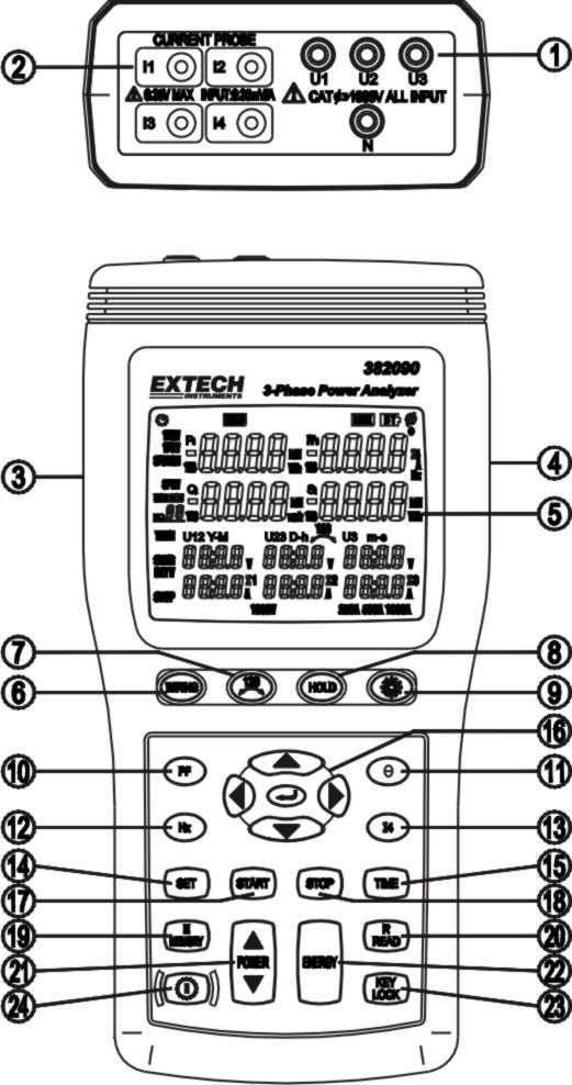
5 Analyzer Description 5
6 1. Input jacks for test leads (U1, U2, U3, N) 2. Input jacks for current probes (I1, I2, I3, I4) 3. Plug for external AC adaptor 4. Optical RS232 PC interface output 5. LCD display 6. WIRING key Select the type of electrical system under test using the WIRING key. Select 1P2W (for signal-phase two-wire power lines), 1P3W (for signal-phase three-wire power lines), 3P3W2M (for three-phase three-wire power line without neutral using the two power meter method; use this selection when measuring three-phase power with 2- current probe measurement only) and 3P4W (for three-phase four-wire power lines with neutral) 7. key Phase sequence detection function key. In the 3P4W mode, press and hold this key to display the phase detection results as follows: Normal phase Reverse phase 8. HOLD key Data hold function key, press HOLD key to freeze displayed reading (the HOLD icon will appear). Press HOLD again to exit Hold function. 9. key Backlight function key, press to turn backlight on or off. The backlight will switch off automatically after 30 seconds. 10. PF key Press to view the power factor value (the PF icon is displayed) 11. Θ key Press to view the measured phase angle value (ψ icon is displayed) 12. Hz key Press to display the measured frequency (the Hz icon is displayed) 13. I4 key Press to display the I4 current probe value (the I4 icon is displayed) 14. SET key Press and hold the TIME key then press the SET key to enter the time set mode and datalogger sampling rate set mode 15 TIME key Press to display the current date and time 16. Used when setting the date and time. Also used to recall manually recorded data 17. START key Press to start the automatic datalogging function 18. STOP key Press to stop/pause the automatic datalogging function. Press START to resume recording. 19. MEMORY Press key to store one reading (set), the M icon and the memory address will display (total manual memory size is 99 sets) 20. READ key Press to recall a manually stored data set 21. POWERPress to display the measured power. Use this button to cycle through the Pt123, Qt123 and St123 displays 22. ENERGY Press to display the total integrated power energy 23. KEY Lock Press to lock all of the keys except the and keys 24. key Power on-off key 6

7 Display Description : Auto power off indicator HOLD : Display hold mode LOCK : Lock-out mode BT : Low battery indication ψ: Phase angle display : Phase angle unit of measure (degrees) 1P2W: Single-phase two-wire power line indicator 1P3W: Single-phase three-wire power line indicator 3P3W2M: Three-phase three-wire power line indicator 3P4W: Three-phase four-wire power line indicator P1: Phase 1 active power indicator P2: Phase 2 active power indicator P3: Phase 3 active power indicator Pt: Total active power indicator and total active energy indicator KW: Active power unit of measure (kilo-watt) KWh, MWh: Active energy units of measure (kilo-watt hours and Mega-watt hours) PF1: Phase 1 power factor indicator PF2: Phase 2 power factor indicator PF3: Phase 3 power factor indicator PFt: Total power factor indicator I4: Current probe No. 4 measurement indicator Hz: Frequency unit of measure (hertz) DATA No.: Manually datalogged memory address (01~99) M : Datalog record indicator; M displays momentarily each time a data set is recorded DATA R No.: Memory address for recalled reading DATA M : Auto datalogging indicator; M flashes each time a data set is recorded. 01 ~ 10: Memory blocks (20,000 max. data sets can be stored) 7
8 FF: Memory full indicator (when 10 memory blocks or 20,000 readings are filled) Q1: Phase 1 reactive power indicator Q2: Phase 2 reactive power indicator Q3: Phase 3 reactive power indicator Qt: Total reactive power indicator and total reactive energy indicator Kvar: Reactive power unit of measure Kvarh, Mvarh: Reactive energy unit of measure S1: Phase 1 apparent power indicator S2: Phase 2 apparent power indicator S3: Phase 3 apparent power indicator St: Total apparent power indicator and total apparent energy indicator KVA: Apparent power unit of measure (Kilo-volt/amps) KVAh: Apparent energy unit of measure (kilo-volt amp hours) MVAh: Apparent energy unit of measure (mega-volt amp hours) TIME: Current date and time indication Y-M D-h m-s: Date and time INTV: Automatic datalogging sampling interval setting indicator START: Energy calculation start-time indicator STOP: Energy calculation stop-time indicator U1, V, A: Single-phase two-wire (1P2W) U1 voltage and I1 current measurement U1, V, A, U2, V, A: Single-phase three-wire (1P3W) U1, U2 voltage and I1, I2 current measurement U12, V, I1, A, U23, V, I2, A: Three-phase, three-wire, two-power method (3P3W2M); U12, U23 voltage and I1, I2 current measurement U1, V, A, U2, V, A, U3, V, A: Three-phase, four-wire (3P4W) U1, U2, U3 voltage and I1, I2, I3 current measurement V: Voltage unit of measure A: Current unit of measure (ampere) 1000V: Voltage range indication 250A, 500A, 1000A: Current range indication (Autoranging) 8
9 Operation CAUTION: Turn the meter off before connecting to the equipment under test. DANGER: Voltage input connectors U1 to U3 are common to input connector N. Input connectors are not insulated; remove all unnecessary test leads. DANGER: Voltage input connectors U1 to U3 are common to input connector N. Input connectors are not insulated; remove all unnecessary test leads. DANGER: Voltage input connectors U1 to U3 are common to input connector N. Input connectors are not insulated; remove all unnecessary test leads. WARNINGS Always set up the measurement first and then connect the test leads to the circuit. Make connections to the instrument first, before connecting leads to a live circuit. Connect the ground lead first and then the voltage leads and current probe; disconnect in reverse order. Remove all test leads that are not in use. Single-Phase 2-Wire (1P2W) Power System Measurement U1 must be connected to the voltage source during the measurement of U2, U3, I1, I2 and I3 since U1 is the main signal source for the entire meter measurement system. A: Line, N: Neutral, G: Ground; Face the arrow toward the load. 1P2W Wiring Connection Diagram 1. Press key to turn the meter on 2. Press the WIRING key to select 1P2W, the 1P2W annunciator will be displayed. 3. Connect the voltage test leads and current probe to the meter. Connect the black voltage test lead to the N terminal. Connect the red voltage test lead to the U1 terminal. Connect the I1 current probe output plug to the I1 jack. To measure ground leakage current, connect the I4 current probe output plug to the I4 jack. 9
10 4. Connect the voltage test leads and current probe to the electrical equipment under test. CAUTION: Turn the meter off before connecting the voltage test leads and the current probe to the electrical equipment under test. Connect the black voltage alligator clip to the Neutral Line N. Connect the red voltage alligator clip to Line A. Press the I1 current probe trigger to open the jaw and then fully enclose Line A. To measure ground leakage current, press the I4 current probe trigger to open the jaw and then fully enclose the Ground Line G. 5. To measure frequency, press the Hz key. To measure the phase angle, press the Θ key. To measure the ground leakage current, press the I4 key. To measure the power factor, press the PF key. 6. To measure energy, press the ENERGY key, the Pt, Qt, St and PFt or ψt annunciators and energy integration start time will display. The energy integration value and the current time will continually update. Press the key to pause the energy calculation; the HOLD annunciator will display. Press the HOLD key to exit the energy measurement mode. 10
11 Single-Phase 3-Wire (1P3W) Power System Measurement U1 must be connected to the voltage source during the measurement of U2, U3, I1, I2 and I3 since U1 is the main signal source for the entire meter measuring system. A, B: Line, N: Neutral, G: Ground; Face the arrow toward the load. 1. Press the key to turn the meter on 1P3W Wiring Connection Diagram 2. Press the WIRING key to select 1P3W, the 1P3W annunciator will display. 3. Connect the voltage test leads and the current probe to the meter. Connect the black voltage test lead to the N terminal. Connect the red voltage test lead to the U1 terminal. Connect the yellow voltage test lead to the U2 terminal. Connect the I1 current probe output plug to the I1 jack. Connect the I2 current probe output plug to the I2 jack. To measure ground leakage, connect the I4 current probe output plug to the I4 jack. 4. Connect the voltage leads and current probe to the electrical equipment to be tested. CAUTION: Turn the meter off before connecting the voltage test leads and the current probe to the electrical equipment under test. Connect the black voltage alligator clip to the neutral line N. Connect the red voltage alligator clip to line A. Connect the yellow voltage alligator clip to line B. Press the I1 current probe trigger to open the jaw and then fully enclose Line A. 11 Press the I2 current probe trigger to open the jaw and then fully enclose Line B. 12 To measure ground leakage current, press the I4 current probe trigger to open the jaw and then fully enclose the ground line G. 5. Use the POWER key to select (P1, Q1, S1, PF1), (P2, Q2, S2, PF2) and (Pt, Qt, St, PFt). 11
12 6. To measure frequency, press the Hz key. To measure phase angle, press the Θ key. To measure ground leakage current, press the I4 key. To measure power factor, press the PF key. 7. To measure energy, press the ENERGY key, the Pt, Θt, St and PFt or ψt annunciators and the energy integration start time will display. The energy integration value and the current time will be continually updated, press the key to pause the energy calculation; the HOLD annunciator will display. Press HOLD to exit the energy measurement mode. 12
13 Three-Phase 3-Wire (3P3W) Power System Measurement U1 must be connected to the voltage source during the measurement of U2, U3, I1, I2 and I3 since U1 is the main signal source of the entire meter measurement system. A, B, C: Line, G: Ground; Face the arrow toward the load 1. Press the key to turn the meter on. 3P3W Wiring Connection Diagram 2. Press the WIRING key to select 3P3W2M; the 3P3W2M annunciator will display. 3. Connect the voltage test leads and current probe to the meter. Connect the black voltage test lead to the N terminal. Connect the red voltage test lead to the U1 terminal. Connect the yellow voltage test lead to the U2 terminal. Connect the I1 current probe output plug to the I1 jack. Connect the I2 current probe output plug to the I2 jack. 4. Connect the voltage test leads and current probe to the electrical equipment to be tested. CAUTION: Turn the meter off before connecting the voltage test leads and the current probe to the electrical equipment under test. Connect the black voltage alligator clip to the line B. Connect the red voltage alligator clip to the line A. Connect the yellow voltage alligator clip to the line C. Press the I1 current probe trigger to open the jaw, and then fully enclose Line A. Press the I2 current probe trigger to open the jaw, and then fully enclose the Line C. 5. Use the POWER key to select (P1, Q1, S1, PF1), (P2, Q2, S2, PF2) & (Pt, Qt, St, PFt) 13
14 6. To measure frequency, press the Hz key. To measure phase angle, press the Θ key. To measure power factor, press the PF key. 7. To measure energy, press the ENERGY key, the Pt, Θt, St and PF or ψt annunciators and the energy integration start time will display. The energy integration value and the current time will continually update, press key to pause the energy calculation; the HOLD annunciator will display. Press HOLD to exit the energy measurement mode. 14
15 Three-Phase 4-Wire (3P4W) Power System Measurement U1 must be connected to the voltage source during the measurement of U2, U3, I1, I2 and I3 since U1 is the main signal source of the entire meter measuring system. A, B, C: Line, N: Neutral, G: Ground; Face the arrow toward the load. 3P4W Wiring Connection Diagram 1. Press the key to turn the meter on. 2. Press the WIRING key to select 3P4W; the 3P4W annunciator will display. 3. Connect the voltage test leads and the current probe to the meter. Connect the black voltage test lead to the N terminal. Connect the red voltage test lead to the U1 terminal. Connect the yellow voltage test lead to the U2 terminal. Connect the blue voltage test lead to the U3 terminal. Connect the I1 current probe output plug to the I1 jack. Connect the I2 current probe output plug to the I2 jack. Connect the I3 current probe output plug to the I3 jack. Connect the I4 current probe output plug to the I4 jack. 4. Connect the voltage test leads and current probe to the electrical equipment to be tested. CAUTION: Turn the meter off before connecting the voltage test leads and the current probe to the electrical equipment under test. Connect the black voltage alligator clip to the neutral line N. Connect the red voltage alligator clip to line A. 11 Connect the yellow voltage alligator clip to line B. 12 Connect the blue voltage alligator clip to line C. 13 Press the I1 current probe trigger to open the jaw and then fully enclose Line A. 14 Press the I2 current probe trigger to open the jaw and then fully enclose Line B. 15 Press the I3 current probe trigger to open the jaw and fully enclose Line C. 16 Press the I4 current probe trigger to open the jaw and fully enclose neutral line N. 15
16 5. Press the POWER key to select (P1, Q1, S1, PF1), (P2, Q2, S2, PF2), (P3, Q3, S3, PF3) or (Pt, Qt, St, PFt) groups. 6. To measure frequency, press the Hz key. To measure phase angle, press the Θ key. To measure neutral line current, press the I4 key. To measure power factor, press the PF key. 7. To measure energy, press the ENERGY key, the Pt, Θt, St and PF or ψt annunciators and the energy integration start time will display. The energy integration value and the current time will continually display, press the key to pause the energy calculation; the HOLD annunciator will display. Press the HOLD key to exit the energy measurement mode. I4 Current Measurement 1. Press the key to turn the meter on. 2. Press the I4 key. 3. Connect the I4 current probe output plug to the I4 jack. 4. Press the I4 current probe trigger to open the jaw and then fully enclose the desired measured wire. 5. Read the I4 value, if the measured current value is greater than 250A, the OL symbol will appear. 16
17 Manual Datalogger Record and Recall Mode Clear memory data 1. Press the key to turn the meter off. 2. Press and hold the MEMORY key and then press the key again to turn the meter on; the CLr annunciator will display and all the manually logged data will be erased. Manually record data 1. Press the MEMORY key once to store one reading (1 set). The M annunciator will display momentarily along with the memory address. 2. Memory size for the manually recorded data is 99 sets max. Recall manually stored data 1. Press the READ key and the R annunciator will display. 2. Use the keys to scroll through the stored data; the location (address) for each data will also display. 3. Press the key to exit the recall mode. Automatic Datalogging Clearing memory data As a safeguard against accidentally deleted logged data the Power Analyzer memory can only be cleared through the software. Please refer to the software operation section for instructions to clear the data. Setting the Calendar Clock and the Automatic Datalogging Sampling Interval 1. Press the TIME key and then quickly press the SET key. Seconds will start blinking. 2. Use the keys to set the current YEAR-month, DAY-hour, minutes-seconds 3. Press the key to access the sampling interval mode; the INTV annunciator will display. 4. Use the keys to select the sampling interval (5 seconds, 30 seconds, 1 minute or 2 minutes). 5. Press the key to exit this mode. Automatic Datalogging Operation 1. Press the START key to begin automatic datalogging: DATA M (block number) will display. The M annunciator will appear each time a reading is recorded. 2. Press the STOP key to pause logging; press START to resume. 3. Data can be recorded in up to 10 memory blocks; the current block number is displayed while logging (the maximum recording capacity is 20,000 readings). 4. When the maximum block or maximum reading limit is reached, the FF annunciator will be displayed and datalogging will stop. Downloading Data to a PC Please refer to the software operation section for data download instructions.. 17
18 Phase Sequence Measurements 1. Press the key to turn the meter on. 2. Use the WIRING key to select 3P4W. 3. Connect the voltage test leads to the meter. Connect the red voltage test lead to the U1 terminal. Connect the yellow voltage test lead to the U2 terminal. Connect the blue voltage test lead to the U3 terminal. 4. Connect the voltage test leads to the electrical equipment to be tested. CAUTION: Turn the meter off before connecting the voltage test leads and the current probe to the electrical equipment under test. Connect the red voltage alligator clip to power line A phase. Connect the yellow voltage alligator clip to power line B phase. Connect the blue voltage alligator clip to power line C phase. 5. U1, U2 and U3 measured voltages must be greater than 30V. Press and hold the key. If the phase sequence is clockwise, the annunciator is displayed. If the phase sequence is counter-clockwise, the annunciator is displayed. Release the key to exit this measurement mode. Voltage/Current Waveform and Harmonic Analyzer Please refer to the software operation section for waveform and harmonic measurement details. Disabling the Auto Power-Off Feature The meter automatically enters the sleep mode after approx. 30 minutes to conserve battery power. 1. To disable this feature: Press the key to turn the meter off. Press and hold the HOLD key and then press the power off symbol will switch off indicating Auto Power off is disabled. key to turn the meter on. The auto 2. The Auto power off mode is enabled each time the meter is turned on. It is automatically disabled in the following modes: ENERGY mode Automatic datalogging When Meter is connected to PC 18
19 RS-232 PC Interface and Software Program Connect the Optical Interface connector to the Power Analyzer (middle pin is keyed for correct orientation). Connect the 9-pin female connector to the 9-pin serial PC port (COM1 or COM2). This meter has the capability to connect to and communicate with a PC. To install and use the software, please refer to the instructions provided on the supplied CD-ROM and/or the instructions provided in the HELP Utility within the software program. Instructions on using the software are included on the CD-ROM. Open the file Software Manual.pdf to access the manual. Check the software download page of the website for the latest version of the PC software and its operating system compatibility. Installing the Windows Application Program 1. Place the supplied software CD in the PC CD-ROM drive 2. Wait for Autorun to start and follow the on-screen instructions 3. If Autorun does not start, click on Start then Run. Type the drive letter of the CD-ROM and :\VB\Disk1\Setup.exe and click OK (To install the LabVIEW version, type the drive letter and :\LV\installer\Setup.exe and click OK). 4. Change the path if necessary or choose install the program to its default location. 5. Launch the program by double clicking the program file in the location where it was saved during installation. 6. Remember not to run the supplied software until the meter is properly connected to the PC as described earlier. 19
20 Specifications General Specifications Maximum voltage between voltage input terminals and earth ground: 1000 Vrms Maximum rated working voltage for current input: 0.35Vrms Maximum current for current probe: 1000A rms Display: Ten (10) 4-digit LCD displays (maximum reading 9999) Batteries 8pcs, 1.5VAA Battery life: approx. 50 hours AC Adaptor 12V DC, 300mA Auto power off: After approx. 30 minutes Low battery indication: BT is displayed when battery voltage falls low Backlight display time: Automatically turns off approx. 30 seconds Sampling rate: Approx. 1 display update every 2 seconds (digital display) Waveform and harmonic analyzer: 54 samples per period Current probe jaw opening diameter: Cables ψ40mm Operating temperature and humidity: 32 to 104 o F (0 to 40 o C); R.H. <80% non-condensing Temperature coefficient: 0.1 (specified accuracy) / <64 or >82 o F (<18 or >28 o C) Storage temperature and humidity: 14 to 140 o F (-10 to 60 o C); R.H. < 70% non-condensing Dimensions (meter): 9.2(L) x 4.6(W) x 2.1(H) ; [235(L) 117(W) 54(H)mm] Dimensions (Current probes): 7.6(L) x 3.5(W) x 1.6(H) ; [193(L) 88(W) 40(H)mm] Weight: Meter: approx oz (730g); Current probe: approx. 11.6oz (333g) Safety This meter is intended for indoor use and protected, against the users, by double insulation per EN and IEC nd Edition (2001) to CAT III 1000V; Pollution Degree 2. The meter also meets UL 61010A-1, First Edition UL Listed The UL mark does not indicate that this product has been evaluated for the accuracy of its readings. Per IEC1010 Measurement Installation Category MEASUREMENT CATEGORY I: Equipment of OVERVOLTAGE CATEGORY I is equipment for connection to circuits in which measures are taken to limit the transient overvoltages to an appropriate low level. Note Examples include protected electronic circuits. MEASUREMENT CATEGORY II: Equipment of OVERVOLTAGE CATEGORY II is energy-consuming equipment to be supplied from the fixed installation. Note Examples include household, office, and laboratory appliances. MEASUREMENT CATEGORY III: Equipment of OVERVOLTAGE CATEGORY III is equipment in fixed installations. Note Examples include switches in the fixed installation and some equipment for industrial use with permanent connection to the fixed installation. MEASUREMENT CATEGORY IV: Equipment of OVERVOLTAGE CATEGORY IV is for use at the origin of the installation. Note Examples include electricity meters and primary over-current protection equipment 20
21 Electrical Specifications Accuracy: ± (% of reading + number of digits) at 64 to 82 o F (18 to 28 o C) with relative humidity to 80% AC Voltage True rms measurements (V) Range Resolution Accuracy 999.9V 0.1V ± (0.5%rdg + 10d) (>80V) Input impedance 2MΩ Note: Minimum Voltage; 50V (0V displayed below 50V) Display: RMS voltage value for each channel AC Current True rms Measurement (A) Autoranging Ranges Resolution Accuracy (including current probe) Current probe output Overload protection 1000Vrms Overload protection 250.0A 500.0A 999.9A 0.1A ±(2%rdg + 20d) 0.35mV/A 1000Arms Note: Minimum Current; 3A (0A displayed below 3A) Display: RMS current value for each channel Active Power measurement P (KW) Nominal frequency 50Hz (382091) 60Hz (382090) Nominal frequency 50Hz (382091) 60Hz (382090) Range Resolution Accuracy (PF=1) Power factor influence (PF=0.5) 999.9KW 0.1KW ± (1.5%rdg + 20d) ± (1%rdg + 10d) Display: Active power of each channel and the sum of multiple channels Polarity display: For influx (consumption) no symbol; For outflow (regenerative) - sign Apparent Power measurement S (KVA) Range Resolution Accuracy (PF=1) Power factor influence (PF=0.5) 999.9KVA 0.1KVA ± (1.5%rdg + 20d) ± (1%rdg + 10d) Measurement method: Calculated from RMS voltage U and RMS current I. Displays: Apparent power of each channel and the sum of multiple channels. Polarity display: Positive assumed Reactive Power measurement Q (KVAR) Range Resolution Accuracy (PF=1) Power factor influence (PF=0.5) 999.9KVAR 0.1KVAR ± (1.5%rdg + 20d) ± (1%rdg + 10d) Measurement method: Calculated from apparent power S and active power P. Displays: Reactive power of each channel and the sum of multiple channels. Polarity display: For phase lag (LAG) current is behind voltage: No symbol. For LEAD phase (LEAD: current ahead of voltage): - sign 21
22 Power Factor measurement (COSψ) Range Resolution Accuracy -1 ~ 0 ~ ± (3%rdg + 30d) Measurement method: Calculated from apparent power S and active power P. Displays: Power factor of each channel and the sum of multiple channels. Polarity display: For phase lag (LAG) current is behind voltage: No symbol; for phase lead (LEAD) current is ahead of voltage: - sign Phase angle measurement (ψ) Range Resolution Accuracy ±11 to >50A: ± digits, 25 to 50A: ± digits (<25A unspecified) Measurement method: Calculated from power factor COSψ Display item: Phase angle of each channel and the sum of multiple channels. Polarity display: For phase lag (LAG: current is behind voltage): No symbol. For phase lead (LEAD: current is ahead of voltage): -. Frequency measurement (Hz) Range Resolution Accuracy Measurement source 60HZ 0.01Hz (0.5%rdg + 1d) Voltage U1 > 80V Measurable input range : > 30V Three Phase Sequence Detection Input voltage range Normal phase indication Reverse phase indication Meas. source 3P > 30V U1, U2 and U3 22
23 Active Power Energy measurement (KWh) Range Resolution Active power accuracy 3.999KWh 0.001KWh 39.99KWh 399.9KWh 3.999MWh 39.99MWh 119.3MWh 0.01KWh 0.1KWh 0.001MWh 0.01MWh 0.1MWh Timer interval ± (1.5%rdg + 20d) 1 sec Timer Accuracy ± 50ppm at 77 o F (25 o C) Measurement display: Displays total active power consumption Apparent Power Energy measurement (KVAh) Range Resolution Apparent power accuracy 3.999KVAh 0.001KVAh 39.99KVAh 399.9KVAh 3.999MVAh 39.99MVAh 119.3MVAh 0.01KVAh 0.1KVAh 0.001MVAh 0.01MVAh 0.1MVAh Timer interval ± (1.5%rdg + 20d) 1 sec Timer Accuracy ± 50ppm at 77 o F (25 o C) Measurement display: Displays total apparent power energy (sum of absolute values). 23
24 Reactive Power Energy measurement (Kvarh) Range 3.999Kvarh Resolution 0.001Kvarh Reactive power accuracy Timer interval Timer Accuracy 39.99Kvarh 399.9Kvarh 3.999Mvarh 39.99Mvarh 119.3Mvarh 0.01Kvarh 0.1Kvarh 0.001Mvarh 0.01Mvarh 0.1Mvarh (1.5%rdg + 20d) 1 sec ±50ppm at 77 o F (25 o C) Measurement display: Displays total reactive power consumption Harmonic measurement (for use with PC on-line analyzer only) Order Accuracy Harmonic Source No. of samples per period 1 ~ 27 3%THD U1, U2, U3 > 100V; I1, I2, I3 > 50A 54 Probes and Accessories Current Clamp (4pcs) Input Output Safety 1000A AC maximum 0.35mV/A CAT III 600V per IEC , Pollution Degree2. : IEC nd Edition and IEC Voltage Test Leads (4pcs) Safety CAT III, 1000V, AC 10A Max Alligator Clips (4pcs) Safety CAT III, 1000V, AC 10A Max 24
25 Maintenance Cleaning Periodically wipe the case with a dry cloth. Do not use abrasives or solvents. Battery Replacement WARNING: To avoid electrical shock, remove the test leads and current probe before replacing the batteries. 1. The LCD will display BT (low battery) when the battery power falls below proper operating levels. 2. Disconnect all test leads and current probes and press the key to turn the meter off. 3. The battery cover is secured at the bottom of the meter case by two screws. Remove these screws to access the battery compartment. 4. Replace the batteries observing polarity and reassemble the meter. 25
26 Warranty FLIR Systems, Inc. warrants this Extech Instruments brand device to be free of defects in parts and workmanship for one year from date of shipment (a six month limited warranty applies to sensors and cables). If it should become necessary to return the instrument for service during or beyond the warranty period, contact the Customer Service Department for authorization. Visit the website for contact information. A Return Authorization (RA) number must be issued before any product is returned. The sender is responsible for shipping charges, freight, insurance and proper packaging to prevent damage in transit. This warranty does not apply to defects resulting from action of the user such as misuse, improper wiring, operation outside of specification, improper maintenance or repair, or unauthorized modification. FLIR Systems, Inc. specifically disclaims any implied warranties or merchantability or fitness for a specific purpose and will not be liable for any direct, indirect, incidental or consequential damages. FLIR s total liability is limited to repair or replacement of the product. The warranty set forth above is inclusive and no other warranty, whether written or oral, is expressed or implied. Calibration, Repair, and Customer Care Services FLIR Systems, Inc. offers repair and calibration services for the Extech Instruments products we sell. NIST certification for most products is also provided. Call the Customer Service Department for information on calibration services available for this product. Annual calibrations should be performed to verify meter performance and accuracy. Technical support and general customer service is also provided, refer to the contact information provided below. Support Lines: U.S. (877) ; International: +1 (603) Technical Support: Option 3; E mail: support@extech.com Repair & Returns: Option 4; E mail: repair@extech.com Product specifications are subject to change without notice Please visit our website for the most up to date information FLIR Commercial Systems, Inc., 9 Townsend West, Nashua, NH USA ISO 9001 Certified Copyright 2013 FLIR Systems, Inc. All rights reserved including the right of reproduction in whole or in part in any form 26
User's Guide. Model (60Hz) Model (50Hz) 1000A 3-Phase Power Analyzer/Datalogger NO.
 Model (50Hz) 1000A 3-Phase Power Analyzer/Datalogger NO.") User's Guide 1000A 3-Phase Power Analyzer/Datalogger Model 382090 (60Hz) Model 382091 (50Hz) P Q S NO. U12 Y-M U23 D-h U3 m-s 1 2 c I4 3 4 Warranty EXTECH INSTRUMENTS CORPORATION warrants this instrument
User's Guide 1000A 3-Phase Power Analyzer/Datalogger Model 382090 (60Hz) Model 382091 (50Hz) P Q S NO. U12 Y-M U23 D-h U3 m-s 1 2 c I4 3 4 Warranty EXTECH INSTRUMENTS CORPORATION warrants this instrument
INSTRUCTION MANUAL. Model True RMS AC/DC 30A Mini Clamp-on Meter. Introduction. True RMS AC Current and Voltage
 INSTRUCTION MANUAL Model 380942 True RMS AC/DC 30A Mini Clamp-on Meter True RMS AC Current and Voltage Measure low current with high resolution to 0.1mA AC and 1mA DC Auto Power Off One touch DCA zero
User's Guide. Extech AM A AC Analog Clamp Meter
 User's Guide Extech AM300 300A AC Analog Clamp Meter Introduction Congratulations on your purchase of the Extech AM300 Analog Clamp Meter. This device measure AC Voltage and Current, DC Voltage, and Resistance.
User s Guide. 600A AC Clamp Meter. Model 38387
 User s Guide 600A AC Clamp Meter Model 38387 Safety International Safety Symbols This symbol, adjacent to another symbol or terminal, indicates the user must refer to the manual for further information.
User's Guide. Phase Sequence and Motor Rotation Tester Model
 User's Guide Phase Sequence and Motor Rotation Tester Model 480403 Introduction Congratulations on your purchase of the Extech Model 408403 Motor and Phase Rotation Indicator. This handheld instrument
True RMS AC Voltage/Current Datalogger
 User's Guide True RMS AC Voltage/Current Datalogger Model DL150 Introduction Congratulations on your purchase of this Voltage or Current datalogger. With this meter, you can monitor and log data over long
User s Guide. 600A True RMS AC/DC Clamp Meter. Model 38389
 User s Guide 600A True RMS AC/DC Clamp Meter Model 38389 Safety International Safety Symbols This symbol, adjacent to another symbol or terminal, indicates the user must refer to the manual for further
Mini Digital Multimeter
 User's Guide Mini Digital Multimeter Model MN15 Introduction Congratulations on your purchase of the Extech MN15 MultiMeter. The MN15 offers AC/DC Voltage, AC/DC Current, Resistance, Diode, and Continuity
User's Guide. MiniTec TM Series Model MN25 MultiMeter
 User's Guide MiniTec TM Series Model MN25 MultiMeter Warranty EXTECH INSTRUMENTS CORPORATION warrants this instrument to be free of defects in parts and workmanship for one year from date of shipment (a
Integrating Sound Level Datalogger Model
 User's Guide Integrating Sound Level Datalogger Model 407780 Introduction Congratulations on your purchase of the Extech 407780 Integrating Sound Level Meter. The 407780 with programmable integrating time
Heavy Duty Datalogger Module
 User's Guide Heavy Duty Datalogger Module Model 380340 Introduction Congratulations on your purchase of Extech s 380340 Datalogger Module. The Datalogger connects to and records data from Extech Heavy
User's Guide. Power Analyzer Model Power Analyzer Datalogger Model Introduction
 User's Guide Power Analyzer Model 380801 Power Analyzer Datalogger Model 380803 Introduction Congratulations on your purchase of the Extech 380801 or 380803 Power Analyzer Datalogger. This device offers
Power Analyzer Datalogger Model
 User's Guide Power Analyzer Model 380801 Power Analyzer Datalogger Model 380803 Extech 380803 Appliance Tester/Power Analyzer Extech 380803 True RMS Power Analyzer Data Logger Extech 380803-NIST True RMS
3-Axis G-Force Datalogger
 User's Guide 3-Axis G-Force Datalogger Model VB300 Introduction Congratulations on your purchase of the VB300 G-Force Datalogger. The Model VB300 can measure and record shock and vibration (acceleration)
Autoranging Multimeter plus IR Thermometer Extech 450 Patented
 User's Guide Autoranging Multimeter plus IR Thermometer Extech 450 Patented Introduction Congratulations on your purchase of the Extech 450 (part number EX450) Autoranging Multimeter plus IR Thermometer.
User's Guide. Cup Thermo-Anemometer. Model AN400
 User's Guide Cup Thermo-Anemometer Model AN400 Introduction Congratulations on your purchase of the Extech Cup Thermo-Anemometer. The AN400 measures air velocity in five units of measure: feet per minute
User's Guide. Model High Precision Quad Output DC Power Supply
 User's Guide Model 382270 High Precision Quad Output DC Power Supply Introduction Congratulations on your purchase of the Extech 382270 DC Power Supply. The Model 382270 can be used for many applications
User Manual. 400Amp AC Clamp Meter + NCV. Model MA430. Additional User Manual Translations available at
 User Manual 400Amp AC Clamp Meter + NCV Model MA430 Additional User Manual Translations available at www.extech.com Introduction Congratulations on your purchase of this Extech MA430 Clamp Meter. This
User Guide. Moisture Meter. Model MO250
 User Guide Moisture Meter Model MO250 Introduction Congratulations on your purchase of the Extech MO250 Moisture Meter. The MO250 detects moisture in wood and other building materials such as brick, wall
User's Guide. Model Laser Photo Tachometer
 User's Guide Model 461920 Laser Photo Tachometer Introduction Congratulations on your purchase of Extech's Mini Laser Photo Tachometer, Model 461920. This Tachometer provides non-contact RPM and Revolution
Dual Input, 3-Display Thermometer/Datalogger Model
 USER GUIDE Dual Input, 3-Display Thermometer/Datalogger Model 421509 Accepts J, K, T, E, R, S, & N thermocouples Internal Memory stores up to 16 data sets, with 1024 maximum data capacity Backlit Electro-luminescent
Mini Photo Tachometer Model Mini Contact Tachometer Model
 User's Guide Mini Photo Tachometer Model 461700 Mini Contact Tachometer Model 461750 Introduction Congratulations on your purchase of the Extech Tachometer. The Model 461700 Photo Tachometer uses precision
SuperHeat Psychrometer Models RH350 and RH355 (kit)
") User's Guide SuperHeat Psychrometer Models RH350 and RH355 (kit) Introduction Congratulations on your purchase of the Extech RH350 SuperHeat Psychrometer. This device measures Differential Temperature
User's Guide SuperHeat Psychrometer Models RH350 and RH355 (kit) Introduction Congratulations on your purchase of the Extech RH350 SuperHeat Psychrometer. This device measures Differential Temperature
Model A Mini AC/DC Clamp Meter. User's Guide
 Model 380950 80A Mini AC/DC Clamp Meter User's Guide Introduction Congratulations on your purchase of the Extech 80A Mini AC/DC Clamp Meter. The Model 380950 measures AC/DC Current, AC/DC Voltage, Resistance,
Heavy Duty Datalogging Light Meter
 User's Guide Heavy Duty Datalogging Light Meter with PC Interface Model HD450 Introduction Congratulations on your purchase of the Extech HD450 Digital Light Meter. The HD450 measures illuminance in Lux
Heavy Duty Datalogger Module
 User's Guide Heavy Duty Datalogger Module Model 380340 Introduction Congratulations on your purchase of Extech s 380340 Datalogger Module. The Datalogger connects to and records data from Extech Heavy
User's Guide. Datalogging Light Meter with PC Interface. Model
 User's Guide Datalogging Light Meter with PC Interface Model 401036 Warranty EXTECH INSTRUMENTS CORPORATION warrants this instrument to be free of defects in parts and workmanship for one year from date
Autoranging Mini Multimeter Model MN16A
 User's Guide Autoranging Mini Multimeter Model MN16A Introduction Congratulations on your purchase of the Extech MN16A Autoranging Multimeter. This meter measures AC/DC Voltage, AC/DC Current, Resistance,
Owner's Manual. True RMS Multimeter. Model No Safety Operation Maintenance Español
 Owner's Manual True RMS Multimeter Model No. 82023 CAUTION: Read, understand and follow Safety Rules and Operating Instructions in this manual before using this product. Safety Operation Maintenance Español
INSTRUCTION MANUAL. Model Dual Input RTD Thermometer. Measures two temperatures simultaneously. Dual RTD probe inputs
 INSTRUCTION MANUAL Model 421504 Dual Input RTD Thermometer Measures two temperatures simultaneously Dual RTD probe inputs Clock and Elapsed Timer functions Special functions include Data Hold, MIN/MAX/AVG,
Heavy Duty Vibration Meter
 User Guide Heavy Duty Vibration Meter Model 407860 Introduction Congratulations on your purchase of the Extech 407860 Vibration Meter. The Model 407860 measures vibration levels in industrial machinery.
Mini Digital Multimeter
 User Manual Mini Digital Multimeter Model MN15A Additional User Manual Translations available at www.extech.com Introduction Congratulations on your purchase of the Extech MN15A MultiMeter. The MN15A offers
User's Manual. Model Heavy Duty Datalogging Module with Windows Software
 User's Manual Model 380340 Heavy Duty Datalogging Module with Windows Software Stores data for later recall and analysis Can be used with any Extech Heavy Duty meter Selectable recording interval Battery
User's Guide. 800 Amp Clamp Meters. EX710 AC Clamp meter EX720 True RMS AC Clamp meter EX730 AC/DC True RMS Clamp meter
 User's Guide 800 Amp Clamp Meters EX710 AC Clamp meter EX720 True RMS AC Clamp meter EX730 AC/DC True RMS Clamp meter Introduction Congratulations on your purchase of the EX710, EX720, or EX730 Clamp DMM.
APO F T1 F T1-T2 ESC - 0 ENTER. [Limits] CLR? SET[ ] LOG READ SAVE READ SHIFT [OFS] [APO] MAX/MIN REL HOLD [TIME] T1-T2 TYPE T1/T2 TYPE T1/T2
![APO F T1 F T1-T2 ESC - 0 ENTER. [Limits] CLR? SET[ ] LOG READ SAVE READ SHIFT [OFS] [APO] MAX/MIN REL HOLD [TIME] T1-T2 TYPE T1/T2 TYPE T1/T2](/thumbs/83/87129247.jpg "APO F T1 F T1-T2 ESC - 0 ENTER. [Limits] CLR? SET[ ] LOG READ SAVE READ SHIFT [OFS] [APO] MAX/MIN REL HOLD [TIME] T1-T2 TYPE T1/T2 TYPE T1/T2") User s Guide Dual Input, 3-Display Thermometer/Datalogger Model 421509 Accepts J, K, T, E, R, S, & N thermocouples Internal Memory stores up to 16 data sets, with 1024 maximum data capacity Backlit Electro-luminescent
User s Guide Dual Input, 3-Display Thermometer/Datalogger Model 421509 Accepts J, K, T, E, R, S, & N thermocouples Internal Memory stores up to 16 data sets, with 1024 maximum data capacity Backlit Electro-luminescent
User's Guide. Model Noise Dosimeter with PC Interface. Introduction
 User's Guide Noise Dosimeter with PC Interface Model 407355 Introduction Congratulations on your purchase of the Extech 407355 Personal Noise Dosimeter. The 407355 is designed to test noise exposure in
User s Manual. Model and Sound Level Calibrators
 User s Manual Model 407744 and 407766 Sound Level Calibrators Introduction Congratulations on your purchase of Extech s Sound Level Calibrator. Extech Calibrators accommodate Sound Level Meters with 0.5
User's Guide. True RMS Multimeter plus IR Thermometer. Extech 470 Patent Pending
 User's Guide True RMS Multimeter plus IR Thermometer Extech 470 Patent Pending Introduction Congratulations on your purchase of the Extech 470 (part number EX470) True RMS Autoranging Multimeter plus IR
User's Guide. Programmable DC Power Supply 200 Watt (40 Volts / 5 Amps) Model Introduction
 Model Introduction") User's Guide Programmable DC Power Supply 200 Watt (40 Volts / 5 Amps) Model 382280 382280 Introduction Congratulations on your purchase of the Extech 382280 Programmable DC Power Supply. This 200 watt
User's Guide Programmable DC Power Supply 200 Watt (40 Volts / 5 Amps) Model 382280 382280 Introduction Congratulations on your purchase of the Extech 382280 Programmable DC Power Supply. This 200 watt
3-Phase Power Analyzer/Datalogger
 User Guide 3-Phase Power Analyzer/Datalogger MODEL PQ3450 99 Washington Street Melrose, MA 02176 Phone 781-665-1400 Toll Free 1-800-517-8431 Visit us at www.testequipmentdepot.com Table of Contents 1.0
User's Guide. Video Borescope. Model BR100
 User's Guide Video Borescope Model BR100 Introduction Congratulations on your purchase of this Extech BR100 Video Borescope. This instrument was designed for use as an inspection device. It can be used
Laser Photo/ Contact Tachometer. m/min. ft/min
 User's Manual Model 461995 Laser Photo / Contact Tachometer Laser Photo/ Contact Tachometer 461995 MEMORY rpm PHOTO CONTACT ft/min m/min Introduction Congratulations on your purchase of Extech's Laser
Digital Vane Thermo-Anemometer Model
 User's Guide Digital Vane Thermo-Anemometer Model 451104 Warranty EXTECH INSTRUMENTS CORPORATION warrants this instrument to be free of defects in parts and workmanship for one year from date of shipment
RS Stock No Instruction Manual RS Input Data Logging Thermometer
 RS Stock No. 730-0458 Instruction Manual RS-1384 4 Input Data Logging Thermometer EN FR IT DE ES TABLE OF CONTENTS / EN TITLE TABLE OF CONTENTS PAGE 1. INTRODUCTION FEATURE... 1 2. SPECIFICATIONS... 2
User's Guide. Heavy Duty Vane Thermo-Anemometer. Model
 User's Guide Heavy Duty Vane Thermo-Anemometer Model 407112 407112 Warranty EXTECH INSTRUMENTS CORPORATION warrants this instrument to be free of defects in parts and workmanship for one year from date
User's Guide. Temperature / Humidity Datalogger. Model 42270
 User's Guide Temperature / Humidity Datalogger Model 42270 Warranty EXTECH INSTRUMENTS CORPORATION warrants this instrument to be free of defects in parts and workmanship for one year from date of shipment
Mini Digital Multimeter
 User's Guide Mini Digital Multimeter Model MN15 99 Washington Street Melrose, MA 02176 Phone 781-665-1400 Toll Free 1-800-517-8431 Visit us at www.testequipmentdepot.com Back to the Extech MN15/MN16 Series
Mini Digital Multimeter Model MN15. User's Guide
 Mini Digital Multimeter Model MN15 User's Guide Introduction Congratulations on your purchase of the Extech MN15 MultiMeter. The MN15 offers AC/DC Voltage, AC/DC Current, Resistance, Diode, and Continuity
User Guide True RMS Multimeter Extech EX205T
 User Guide Extech EX205T True RMS Digital Multimeter Extech EX210T True RMS Digital Multimeter IR True RMS Multimeter Extech EX205T Introduction Thank you for selecting the Extech EX205T True RMS Auto-ranging
User's Guide. Vibration Meter and Laser Combination Tachometer Model
 User's Guide Vibration Meter and Laser Combination Tachometer Model 461880 Introduction Congratulations on your purchase of the Extech 461880 Vibration Meter and Combination Laser Tachometer. The 461880
User's Guide. Heavy Duty Differential Pressure Manometer. Model
 User's Guide Heavy Duty Differential Pressure Manometer Model 407910 Warranty EXTECH INSTRUMENTS CORPORATION warrants this instrument to be free of defects in parts and workmanship for one year from date
User's Guide Video Borescope Model BR200
 User's Guide Video Borescope Model BR200 Introduction Congratulations on your purchase of this Extech BR200 Video Borescope. This instrument was designed for use as a remote inspection device. It can be
User's Guide. Model RPM10 Laser Photo / Contact Tachometer with IR Thermometer. Patented
 User's Guide 99 Washington Street Melrose, MA 02176 Fax 781-665-0780 TestEquipmentDepot.com Model RPM10 Laser Photo / Contact Tachometer with IR Thermometer Patented Introduction Congratulations on your
User Guide. ExStik TM Model RE300 Waterproof ORP Meter. Patent Pending RE300 ORP
 0 User Guide ExStik TM Model RE300 Waterproof ORP Meter Patent Pending 500 MV 1000 TM RE300 ORP ExStik TM Description Front Panel Controls 1. Battery compartment cap 2. LCD Display 3. MODE button 4. CAL
User's Manual. Autoranging Datalogging Insulation Tester (Megohmmeter) with PC Interface. Model
 with PC Interface. Model") User's Manual Autoranging Datalogging Insulation Tester (Megohmmeter) with PC Interface Model 380366 Introduction Congratulations on your purchase of the Extech 380366 Datalogging Insulation Tester. The
User's Manual Autoranging Datalogging Insulation Tester (Megohmmeter) with PC Interface Model 380366 Introduction Congratulations on your purchase of the Extech 380366 Datalogging Insulation Tester. The
Autoranging Mini Multimeter
 User Manual Autoranging Mini Multimeter Model MN16A Additional User Manual Translations available at www.extech.com Introduction Congratulations on your purchase of the Extech MN16A Autoranging Multimeter.
Heavy Duty Mini Vane CFM Thermo Anemometer
 User's Manual Heavy Duty Mini Vane CFM Thermo Anemometer Model 407117 WARRANTY EXTECH INSTRUMENTS CORPORATION warrants this instrument to be free of defects in parts and workmanship for three years from
User Guide. Heavy Duty Differential Pressure Manometer. Model HD750
 User Guide Heavy Duty Differential Pressure Manometer Model HD750 Warranty EXTECH INSTRUMENTS CORPORATION (A FLIR COMPANY) warrants this instrument to be free of defects in parts and workmanship for three
USER MANUAL. True RMS Multimeter. Extech EX430A
 USER MANUAL True RMS Multimeter Extech EX430A Introduction Congratulations on your purchase of the Extech EX430A True RMS Autoranging Multimeter. This meter measures AC/DC Voltage, AC/DC Current, Resistance,
Digital Sound Level Meter
 User's Guide Digital Sound Level Meter Model 407732 Test Equipment Depot - 800.517.8431-99 Washington Street Melrose, MA 02176 FAX 781.665.0780 - TestEquipmentDepot.com information. A Return Authorization
User Manual. Thermocouple Datalogging Thermometer. Model EA15
 User Manual Thermocouple Datalogging Thermometer Seven (7) Thermocouple input types K, J, T, E, R, S, N Dual thermocouple Input with PC Interface Model EA15 Additional User Manual Translations available
User Guide. Model Temperature Datalogger Kit Model Temperature and Humidity Datalogger Kit Model SW276 Datalogging Software SW276
 User Guide Model 42265 Temperature Datalogger Kit Model 42275 Temperature and Humidity Datalogger Kit Model SW276 Datalogging Software SW276 Introduction Congratulations on your purchase of Extech Instrument
User's Manual Sound Level Alert Model SL130
 User's Manual Sound Level Alert Model SL130 Meets ANSI and IEC Type 2 Sound Level Meter Standards Settable High Limit with large bright High/Low indication and Alarm Output Wall or Desk mountable Extra
User's Guide. Digital Sound Level Meter. Model
 User's Guide Digital Sound Level Meter Model 407730 Introduction Congratulations on your purchase of the Extech 407730 Digital Sound Level Meter. The 407730 measures and displays sound pressure levels
USER MANUAL. Mini Multimeter with Non-Contact Voltage Detector (NCV) Model EX310
 Model EX310") USER MANUAL Mini Multimeter with Non-Contact Voltage Detector (NCV) Model EX310 Introduction Congratulations on your purchase of the Extech EX310 MultiMeter. The EX310 offers AC/DC Voltage, AC/DC Current,
USER MANUAL Mini Multimeter with Non-Contact Voltage Detector (NCV) Model EX310 Introduction Congratulations on your purchase of the Extech EX310 MultiMeter. The EX310 offers AC/DC Voltage, AC/DC Current,
AutoRanging Digital MultiMeter
 Owner's Manual AutoRanging Digital MultiMeter Model No. 82175 CAUTION: Read, understand and follow Safety Rules and Operating Instructions in this manual before using this product. Safety Operation Maintenance
ENGLISH. User manual.
 ENGLISH User manual Copyright HT ITALIA 2012 Release EN 2.00-18/12/2012 Table of contents: 1. PRECAUTIONS AND SAFETY MEASURES... 2 1.1. Preliminary instructions... 2 1.2. During use... 3 1.3. After use...
USER GUIDE. Dual Input True RMS AC Voltage/Current Datalogger. Model DL160
 USER GUIDE Dual Input True RMS AC Voltage/Current Datalogger Model DL160 Introduction Congratulations on your purchase of this Dual Input Voltage / Current datalogger. With this meter, you can monitor
CM-220 True RMS AC CLAMP METER INSTRUCTION MANUAL
 CM-220 True RMS AC CLAMP METER INSTRUCTION MANUAL Safety International Safety Symbols This symbol, adjacent to another symbol or terminal, indicates the user must refer to the manual for further information.
User's Guide. Vane Thermo-Anemometer Datalogger. Model Introduction
 User's Guide Vane Thermo-Anemometer Datalogger Model 451126 Introduction Congratulations on your purchase of Extech's Thermo-Anemometer Datalogger. This Vane-type Anemometer can indicate Air Velocity in
Heavy Duty Psychrometer + IR Thermometer Model HD500
 User Guide Heavy Duty Psychrometer + IR Thermometer Model HD500 Introduction Congratulations on your purchase of the Extech HD500 Psychrometer. This handheld meter measures and displays Air Temperature,
Industrial Multimeter Extech EX510
 User's Guide Industrial Multimeter Extech EX510 Introduction Congratulations on your purchase of the Extech EX510 Autoranging Multimeter. This meter measures AC/DC Voltage, AC/DC Current, Resistance, Frequency
User's Guide. Hot Wire Thermo-Anemometer Model
 User's Guide Hot Wire Thermo-Anemometer Model 407123 Introduction Congratulations on your purchase of the Extech Hot Wire Anemometer. This instrument measures air flow and temperature by placing the sensor
User's Guide. Hot Wire Thermo-Anemometer Model Introduction
 User's Guide Hot Wire Thermo-Anemometer Model 407123 Introduction Congratulations on your purchase of the Extech Hot Wire Anemometer. This meter measures air flow and temperature by placing the sensor
OPERATING INSTRUCTION
 OPERATING INSTRUCTION AUTORANGING MULTIMETER MAX Ω F C 10A MAX every 15 min. COM V SAFETY INFORMATION The following safety information must be observed to insure maximum personal safety during the operation
User's Guide. Digital Multimeter. Model MN42
 User's Guide Digital Multimeter Model MN42 Introduction Congratulations on your purchase of the Extech MN42 MultiMeter. The MN42 offers AC/DC Voltage, DC Current, and Resistance testing. Proper use and
S-14 S-14. Compact Digital Multimeter. Compact Digital Multimeter
 S-14 Compact Digital Multimeter S-14 Compact Digital Multimeter SAFETY INFORMATION The following safety information must be observed to insure maximum personal safety during the operation at this meter
RS Stock No Instruction Manual RS Input Data Logging Thermometer
 RS Stock No. 730-0458 Instruction Manual RS-1384 4 Input Data Logging Thermometer EN FR IT DE ES TABLE OF CONTENTS / EN TITLE TABLE OF CONTENTS PAGE 1. INTRODUCTION FEATURE... 1 2. SPECIFICATIONS... 2
Model R5010. TRMS Digital Multimeter. Instruction Manual
 INSTRUMENTS Model R5010 TRMS Digital Multimeter Instruction Manual Table of Contents Safety...3-4 IEC1010 Overvoltage Installation Category... 3 Warnings... 4 Features... 5 Specifications...5-8 Instrument
Model: Pro93 TRUE RMS LEAKAGE CURRENT TESTER
 Model: Pro93 TRUE RMS LEAKAGE CURRENT TESTER CONTENTS TITLE PAGE I. Safety Information.......1 Environmental Conditions... 1 Explanation of Symbols..... 1 II. Specification..... 2 General Specification...
Indoor Air Quality Meter/Datalogger
 User Manual Indoor Air Quality Meter/Datalogger Model EA80 CC Additional User Manual Translations available at www.extech.com Introduction Congratulations on your purchase of the Extech EA80 Indoor Air
DM-918 OPERATIONS MANUAL AUTORANGING MULTIMETER
 DM-918 OPERATIONS MANUAL AUTORANGING MULTIMETER SAFETY INFORMATION The following safety information must be observed to ensure maximum personal safety during the operation of this meter: This meter is
User Guide. Indoor Air Quality Meter/Datalogger. Model EA80
 User Guide Indoor Air Quality Meter/Datalogger Model EA80 Introduction Congratulations on your purchase of the Extech EA80 Indoor Air Quality Meter. This meter measures Carbon Dioxide (CO 2, ppm) levels,
True RMS Industrial Multimeter Extech EX520
 User's Guide True RMS Industrial Multimeter Extech EX520 Introduction Congratulations on your purchase of the Extech EX520 True RMS Autoranging Multimeter. This meter measures AC/DC Voltage, AC/DC Current,
True RMS Multimeter with IR Thermometer
 Owner's Manual True RMS Multimeter with IR Thermometer Model No. 82024 CAUTION: Read, understand and follow Safety Rules and Operating Instructions in this manual before using this product. Safety Operation
User's Guide Extech EX840 True RMS 1000 Amp Clamp Meter with IR Thermometer
 User's Guide Extech EX840 True RMS 1000 Amp Clamp Meter with IR Thermometer Patented Introduction Congratulations on your purchase of the Extech EX840 CAT IV True RMS 1000A Clamp Meter. This meter measures
User's Guide. EasyView K-Type Thermometer. Model EA11A
 User's Guide EasyView K-Type Thermometer Model EA11A Introduction Congratulations on your purchase of the Extech EasyView Thermometer. This device offers a single K-type thermocouple input with multifunction
ATK-2040 AC/DC TRMS Watt Clamp Meter Users Manual
 ATK-2040 AC/DC TRMS Watt Clamp Meter Users Manual EN 61010-2-032 CAT II 600V, CAT III 300V Pollution Degree 2 SYMBOLS showed on the clamp meter or in this manual: Caution, risk of danger. Refer to accompanying
9040/9040UK. Users Manual. Phase Rotation Indicator
 9040/9040UK Phase Rotation Indicator Users Manual PN 2438546 April 2005 2005 Fluke Corporation. All rights reserved. Printed in China All product names are trademarks of their respective companies. LIMITED
Model R5010. Instruction Manual. TRMS Digital Multimeter. reedinstruments www.
 Model R5010 TRMS Digital Multimeter Instruction Manual reedinstruments www com Table of Contents Safety...3-4 Features... 5 Specifications...5-8 Instrument Description...8-9 Operating Instructions...10-16
Autoranging True RMS Multimeter User Manual
 Autoranging True RMS Multimeter User Manual Please read this manual before switching the unit on. Important safety information inside. Contents Page 1. Safety Information... 4 2. Safety Symbols... 5 3.
User's Guide. Mini Microscope. Model MC108
 User's Guide Mini Microscope Model MC108 Introduction Congratulations on your purchase of this Extech Meter. This digital microscope with 7 to 27X optical magnification, 4X digital zoom, image capture
R5050. Model. Instruction Manual. TRMS AC/DC Clamp Meter. reedinstruments. www. com
 Model R5050 TRMS AC/DC Clamp Meter Instruction Manual reedinstruments com Table of Contents Safety... 3 Features... 4 Specifications...4-6 Instrument Description...7-8 Measurement Procedures...9-12 Battery
True RMS Multimeter with IR Thermometer
 User Guide True RMS Multimeter with IR Thermometer Extech EX210T Introduction Thank you for selecting the Extech EX210T True RMS Autoranging Multimeter. This meter measures AC/DC Voltage, AC/DC Current,
User Guide. ExStik FL700. Fluoride Meter
 User Guide ExStik FL700 Fluoride Meter Introduction The model FL700 is a system specifically designed for the quick and accurate measurement of fluoride ions in drinking water and other aqueous samples.
User's Guide. Digital Multimeter plus IR Thermometer. Extech 450 Patented
 User's Guide Digital Multimeter plus IR Thermometer 99 Washington Street Melrose, MA 02176 Phone 781-665-1400 Toll Free 1-800-517-8431 Visit us at www.testequipmentdepot.com Extech 450 Patented Introduction
1200A 3-Phase Power Analyzer/Datalogger
 User s Manual 1200A 3-Phase Power Analyzer/Datalogger MODEL 382100 Table of Contents 1.0 INTRODUCTION 1-1 Features.... 3 1-2 Safety...4 2.0 SPECIFICATIONS 2-1 General Specifications....5 2-2 Electrical
User's Manual. Digital Sound Level Meter. Model
 User's Manual Digital Sound Level Meter Model 407768 Introduction Congratulations on your purchase of the Extech 407768 Sound Level Meter. This Auto Range Sound Level Meter meets ANSI and IEC Type II accuracy
Extech EX820 True RMS 1000 Amp Clamp Meter with IR Thermometer. User's Guide
 Extech EX820 True RMS 1000 Amp Clamp Meter with IR Thermometer User's Guide Introduction Congratulations on your purchase of the Extech EX820 True RMS 1000A Clamp Meter. This meter measures AC/DC Voltage,
Mini Multimeter with Non-Contact Voltage Detector (NCV)
") User Guide Mini Multimeter with Non-Contact Voltage Detector (NCV) Model EX330 99 Washington Street Melrose, MA 02176 Phone 781-665-1400 Toll Free 1-800-517-8431 Visit us at www.testequipmentdepot.com
User Guide Mini Multimeter with Non-Contact Voltage Detector (NCV) Model EX330 99 Washington Street Melrose, MA 02176 Phone 781-665-1400 Toll Free 1-800-517-8431 Visit us at www.testequipmentdepot.com