PoKeys Pulse engine v2 documentation
|
|
|
- Lawrence Newton
- 6 years ago
- Views:
Transcription

1 Version: 6/3/2016
2 SAFETY INFORMATION! This product is intended for integration by the user into a computer numerical control (CNC) machine. It is the user's responsibility to assess the overall system design and address all safety considerations that affect the users and equipment. The user assumes all responsibility for system design, including compliance with regulatory standards and codes issued by the applicable entities. PoLabs do not make any claims as to the suitability of this equipment for the user s application. Serious personal injury or equipment damage can occur from the improper integration, installation or operation of this product. This product is not guaranteed to be fail-safe. The system that this equipment is used with shall be fitted with a separate means of fail-safe protection, emergency-stop capability and/or system power removal. This equipment may be connected to dangerous power sources, including electrical power sources. Dangerous voltage levels may be present at this equipment or at connected devices. Measures must be taken to prevent persons from contacting voltage sources which may be present. Equipment should be housed inside an enclosure suitable for the intended environment. Safety interlocks should be provided to prevent any and all dangers to personnel. CNC machine tools are inherently dangerous, and can cause injury to operators and maintenance personnel. Operators and maintenance personnel shall be properly trained in the safe use, operation and maintenance of such machines. Automated machines that this equipment may be used with can move at any time. All persons exposed to such machines must understand the dangers that are present. 2
.")
3 Description PoKeys Pulse engine v2 (upgrade of the original PoKeys Pulse engine) is available on PoKeys56U, PoKeys56E and PoKeys57E devices and enables a direct control of a positioning systems that accepts step/direction signals (stepper motors, servo systems, etc.). PoKeys Pulse engine can operate in standalone (rapid positioning and speed control mode, homing, probing) or in slave mode (under the commands of the PC application). Each axis supports two end (limit) switch inputs, one home (reference position) switch input, which can be either a dedicated one or shared with limit switch inputs. All inputs can are fully configurable (input polarity, placement) using the PoKeys protocol (used by PoKeys application or a third party application for motion control). In addition, operations in each axis can be limited using the soft limit function, where minimum and maximum permissible axis position is specified - once enabled, the axis is put to a stop when exceeding the allowed range, but is free to move in other direction. Each axis can be assigned a different encoder with a customizable multiplication factor for the operation with MPG (manual pulse generator). PoKeys Pulse engine also supports a dedicated emergency switch input, which stops the pulse generation. Figure 1: PoKeys Pulse engine connections for use with the integrated pulse generator 3
4 Table of contents Description... 3 Pulse generator selection... 6 PoKeys device pins in use... 7 Integrated pulse generator - up to 3 axes at 25 khz step frequency... 7 External pulse generator with dedicated IO capability - up to 8 axes at 125 khz step frequency pin motor driver connector pinout... 9 Dedicated axis switch inputs... 9 Relay outputs... 9 Open-collector outputs V voltage output Additional digital inputs Pulse engine limitations: PoKeys Mach3 plugin Installing plugin PoKeys Mach3 plugin existing functionality Configuring plugin for the first time Enabling Pulse engine Motors/axis setup Axis switches configuration Setting up digital inputs and outputs mapping Pendant mode PoPendant configuration Encoder (MPG) settings MPG (manual pulse generator) setup PoKeys IO status Other (miscellaneous) settings Reading and writing of IO from VB script Example script (finds the PoKeys device with the serial number 25000, then toggles the IO 1 on and off at a rate of 1 Hz): Additional OEM buttons Additional OEM LEDs Pulse engine v2 operating principles Modes of operation
5 Safety charge-pump output Motor driver enable outputs Axis parameters Custom external pulse generator without IO functionality Frequently asked questions
 using PoExtensionOC16 or third-party custom board.")
6 Pulse generator selection Pulse engine supports different pulse generators: - Integrated pulse generator (for up to 3 stepper motors with step frequencies up to 25 khz) - External pulse generator without dedicated IO capabilities (for up to 8 stepper motors with step frequencies up to 125 khz) using PoExtensionOC16 or third-party custom board. - External pulse generator with dedicated IO capabilities (for up to 8 stepper motors with step frequencies up to 125 khz, dedicated limit+, limit-, home/ref, axis error inputs, 3 relay outputs, 4 open-collector outputs, 0-10 V output) using PoKeysCNCaddon (pictured below). PoKeysCNCaddon inputs and outputs are galvanically isolated from PoKeys board. Figure 2: PoKeysCNCaddon v1.0 6
7 PoKeys device pins in use Integrated pulse generator - up to 3 axes at 25 khz step frequency Pin Function 38 Direction output x 39 Direction output y 40 Direction output z 46! Step output x 48! Step output y (external 470 Ω pull-up resistor required) 49! Step output z (external 470 Ω pull-up resistor needed) 52 Emergency switch input 53 Safety charge pump 5 khz output Inputs for limit, home and probing switches can be freely connected to any PoKeys pin and configured in software. Remarks: - Watch for pin 47! It is not used for step output! - All switch inputs expect normally closed (NC) switches and must be connected between specified PoKeys input pin and ground. - We advise adding an additional 1 kω pull-up resistor on pins with an external switch - Emergency switch must be connected in such way so that it cuts the power supply to the motors when the switch is activated. External pull-up resistor wiring for pins 48 and 49 7

8 External pulse generator with dedicated IO capability - up to 8 axes at 125 khz step frequency 1 Please pay attention to connecting the PoKeysCNCaddon to PoKeys device. PoKeysCNCaddon connects to PoKeys using the Expansion port flat cable, attached to the board. The Expansion port signals should be connected to PoKeys as follows: Pin Description PoKeys56U pin PoKeys56E/57E pin 1 5 V power supply to the PoKeysCNCaddon - must supply at 5 V 5 V (red) least 400 ma for correct operation 2 PoKeys ground (not to be used for PoKeysCNCaddon IO) GND GND 3 PWM signal for 0-10 V output Signal for IO capabilities (output) Signal for IO capabilities (output) Signal for IO capabilities (output) Signal for IO capabilities (input) Signal for pulse generation Signal for pulse generation Signal for pulse generation Red = galvanically connected to PoKeys PoExtension connector 10-pin connections to motor drivers 3 additional digital inputs 8x Limit- Home/Ref Limit+ signals Vmax adjustment 3 NO relay contacts 4 OC outputs, 0-10 V output, Spindle error, GND 1 Note that PoKeys Mach3 plugin supports only 4 axes 8
 and the correspoding input. Select 'Dedicated pin' in the axis settings.")

9 10-pin motor driver connector pinout Pin Function 1 Axis enable output 3 Direction output 5 Step output 7 Error input 2, 4, 6, 8, 10 GND 9 Not connected Dedicated axis switch inputs All inputs have built-in pull-up resistor - switches must be connected between GND (on the PoKeysCNCaddon) and the correspoding input. Select 'Dedicated pin' in the axis settings. -AX8 RefAX8 +AX8 -AX7 RefAX7 +AX7 -AX6 RefAX6 +AX6 -AX5 RefAX5 +AX5 -AX4 RefAX4 +AX4 -AX3 RefAX3 +AX3 -AX2 RefAX2 +AX2 -AX1 RefAX1 +AX2 Pin (from Function Pin Function top to (continued bottom) ) -AX8 Limit- for axis 8 -AX4 Limit- for axis 4 RefAX8 Ref/home for axis 8 RefAX4 Ref/home for axis 4 +AX8 Limit+ for axis 8 +AX4 Limit+ for axis 4 -AX7 Limit- for axis 7 -AX3 Limit- for axis 3 RefAX7 Ref/home for axis 7 RefAX3 Ref/home for axis 3 +AX7 Limit+ for axis 7 +AX3 Limit+ for axis 3 -AX6 Limit- for axis 6 -AX2 Limit- for axis 2 RefAX6 Ref/home for axis 6 RefAX2 Ref/home for axis 2 +AX6 Limit+ for axis 6 +AX2 Limit+ for axis 2 -AX5 Limit- for axis 5 -AX1 Limit- for axis 1 RefAX5 Ref/home for axis 5 RefAX1 Ref/home for axis 1 +AX5 Limit+ for axis 5 +AX1 Limit+ for axis 1 Relay outputs PoKeysCNCaddon board features 3 relay outputs with normally-open contacts. Rating: - max. 7A/240VAC, max. 10A/125VAC or max. 10A/28VDC. 9


10 Open-collector outputs PoKeysCNCaddon board features 4 open-collector outputs with LEDs for signaling the output state. Rating: - Maximum applied voltage: 80 V - Maximum DC current: up to 50 ma 0-10 V voltage output PWM signal is used to create the 0-10 V voltage output. PWM signal with 0% duty cycle produces 0 V on output, while 100% duty cycle produces Vmax on output. Vmax can be adjusted using the potentiometer 'Vout'. In order to convert PWM signal to an analog output, a low-pass filter with the time constant of 1 ms is applied to the source signal. In order to avoid ripples in the analog output, use PWM frequency of 10 khz or more. Setup/calibration: either set the duty cycle to 100% or connect the PWM signal input to PoKeysCNCaddon board (pin 3) to +3.3V. Use the multimeter to measure voltage between GND adn 0-10 V output. Use the Vout adjustment potentiometer to adjust the voltage to 10 V ( Additional digital inputs There are 4 additional digital inputs: spindle error input and 3 general purpose external digital inputs, available on the top right corner of the PoKeysCNCaddon board. 10
11 Pulse engine limitations: - Minimum/maximum position: o Internal motion controller: -/+ ~16.8 million ticks o External (buffered) mode: -/+ ~2100 million ticks 11

12 PoKeys Mach3 plugin Installing plugin In order to install PoKeys Mach3 plugin, simply copy the Pokeys.dll to the Mach3 plugin folder (by default C:\Mach3\Plugins\). Also, install the latest PoKeys software using the provided setup file. PoKeys Mach3 plugin existing functionality - 3-/4-axis CNC machine support - Support for PoKeys55, PoKeys56U, PoKeys56E and PoKeys57E devices - Mapping of PoKeys digital inputs to Mach3 OEM LEDs and OEM buttons - Mapping of Mach3 OEM LEDs to PoKeys digital outputs - Mapping of PoKeys encoders to Mach3 DROs - Support for matrix keyboard - Support for kbd48cnc keyboard on I2C address 1 - Support for PWM outputs - Support for alphanumeric LCD display - Support for analog inputs (analog joystick, analog to DRO mapping, offsets and gains adjustment, automatic calibration) - Support for IO mapping (Mach3 native input-output pins, additional 100 Mach3 IO device pins - device name PoKeys_{serial number}) - Dedicated menu for each device - Support for pendant with the activation switch - Usage of PoKeys Pulse engine (available on PoKeys56U and Pokeys56E devices) as external motion controller for Mach3 - Safety charge pump output on pin 53 - External motion controller homing support - Soft-limits and limit-override support - Probing support Configuring plugin for the first time Open Mach3 and go to Config -> Config plugins.. The following dialog will appear. 12
.")
.")

13 Enable the Pokeys-Polabs plugin and click CONFIG to start configuring the plugin. PoKeys plugin support multiple PoKeys devices (PoKeys55, PoKeys56U and PoKeys56E). To add a new device configuration, click the Add new button and select the PoKeys device (as illustrated in the image below). After new device configuration is added, Mach3 MUST BE RESTARTED! After restart, the option Configure is enabled. This opens the device configuration dialog where user can configure the device. The same can be achieved using a dedicated device menu entry in the Mach3 Plugin Control menu. 13

14 Enabling Pulse engine In order to use Pulse engine support, go to device configuration, switch to Pulse engine tab and enable one of the following options: - Integrated 3ch: use the integrated pulse engine support in PoKeys56U and PoKeys56E. This option supports step frequencies up to 25 khz - External 4ch without IO: use the pulse engine with conjunction with a simple external pulse engine adapter. This option supports step frequencies up to 125 khz. - External 4ch with IO: use the pulse engine with PoKeysCNCaddon external boards. This option supports step frequencies up to 125 khz. After selecting one of the options above, click OK and restart Mach3 in order to allow Mach3 recognize an external motion controller. On the next Mach3 startup, the following dialog will appear, notifying you that the motion control hardware plugin was detected. Select PoKeys-Polabs and click OK. To enable Pulse engine, the emergency switch input must be connected between pin 52 and ground. The switch must be NC (normally closed) type. At this step, configure the axes as normally through Config -> Motor tuning. See below for details. 14
. Other settings are ignored.")

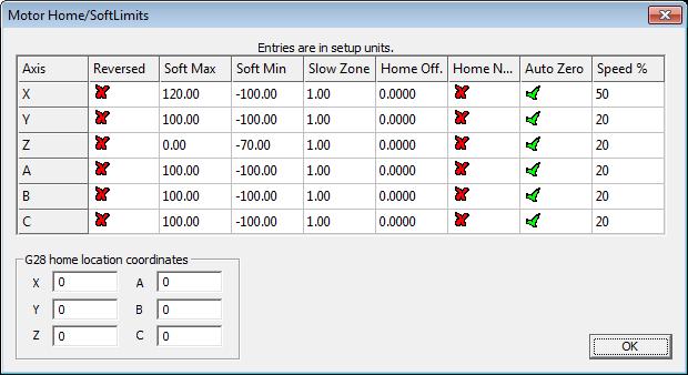
15 Motors/axis setup Open Config > Ports & Pins. The following dialog will appear. Please check that the X, Y and Z axis are enabled (enable A Axis if external pulse generator is used). Other settings are ignored. After enabling the axes, open the Motor tuning dialog (Config > Motor tuning). Follow the Mach3 motor tuning procedure to setup the appropriate values for Steps per, Velocity and Acceleration for each axis. The Step pulse and Dir pulse options are IGNORED. To setup Home/Soft Limits, go to the menu Config > Homing/Limits. In this dialog, software limits and homing speeds can be setup. Use the 'Reversed' and 'Home neg' options to setup the axes directions. Please note that 'Slow Zone' is not supported. 15
16 16
 and switch to Pulse engine settings tab. The following dialog appears. There is a separate drop-down menu for each available switch.")
17 Axis switches configuration In order to configure the axis switches, open Device configuration (either via Config Plugins or via a dedicated device configuration menu in Plugin Control main menu in Mach3) and switch to Pulse engine settings tab. The following dialog appears. There is a separate drop-down menu for each available switch. If external pulse engine with IO functionality is selected, external dedicated option can be selected in the menu for each switch or a standard PoKeys digital input pin (the latest is the only option to use when using integrated pulse engine or external pulse engine without IO functionality). Home/ref switch has some additional options: - Shared with Limit-: Limit- switch functions both as Limit- and as home position switch. During homing, Limit- functionality is temporarily disabled - Shared with Limit+: same as above, but with Limit+ switch All switches can be inverted - the green/red blocks on the left of the switch selection options display the current switch status, with green indicating a free (non-tripped) switch and red indicating tripped switch. Use the 'Invert' option to switch between the states if necessary. If limit switches are enabled, PoKeys Pulse engine will enter emergency mode if any limit switch gets triggered. The probing input option is available at the bottom of the dialog and offers mapping the probing input to either external digital inputs or PoKeys digital input pins. 17

18 Setting up digital inputs and outputs mapping To access the digital inputs and output mapping, open the menu PlugIn control > Configure PoKeys {your serial number}. The following dialog will appear PoKeys digital input or output Mapping to Mach3 OEM button Selected IO function Mapping to Mach3 OEM LED Mapping to Mach3 IOs Use invert option to invert the digital input or output state First column displays a list of all inputs or outputs, available on your PoKeys device. Use the tree structure to navigate between different peripherals and their IO pins. The second column displays the pin function. If the pin is assigned a special function, a description of this function will be displayed. If multiple special functions are assigned, a red 'Conflict' warning will be displayed. Third column (available for digital inputs and outputs) enables selection of mapping to Mach3 OEM LEDs. If the pin function is set to 'Input', this mapping will enable setting of Mach3 OEM LED state based on PoKeys IO pin state. If the pin function is set to 'Output', Mach3 OEM LED state will be reflected to PoKeys IO pin state. Fourth column (available only for digital inputs) enables selection of IO mapping to Mach3 OEM buttons. When PoKeys IO pin is triggered, the selected Mach3 OEM button will be triggered also. Fifth column (available for digital inputs and outputs) enables selection of mapping to/from Mach3 IOs (outputs, such as spindle relay, vacuum, used internally by Mach to control different external devices and inputs, such as limit, home switches, used internally by Mach to detect the status of the machine) and Mach3 IODevice inputs and outputs (accessible via VBScript). 18
.")
19 Pendant mode Plugin supports the usage of pendant with activation switch. If such pendant is connected to PoKeys, 'Pendant mode' should be enabled (checkbox at the bottom of the 'PoKeys mapping' dialog). In this mode, jog action will be deactivated when the activation switch is released and will be automatically activated when there is a signal detected for both the axis and step selection. 19
20 PoPendant configuration Use the following table to configure PoPendant with Mach3. Activate 'Pendant mode' in Mapping page in order to activate the MPG jogging activation/deactivation using the 'Control switch' on the side of the PoPendant. The configuration can also be downloaded (see PoPendant homepage) and imported into Mach3 (go to Import/Export tab in plugin configuration and select 'PoKeys pin mapping' and 'Encoder settings and mapping', then click on 'Import' and select the PoPendant configuration file). Note: the following table only gives an example on how to connect the PoPendant to PoKeys device. To ease the setup process, the configuration file for this example is provided on PoPendant homepage. Wiring can be rearranged by the user, but the plugin configuration must be adjusted accordingly. If PoKeys Pulse engine is used, 'Let PoKeys handle MPG jogging' must be checked in encoder configuration page. Wire PoPendant "wire colour" Function PoKeys pin number Mach3 Mapping 1 red MPG +5V 5V / 2 black MPG GND GND / 3 green MPG A 1 MPG1 B 4 white MPG B 2 MPG1 A 3* purple N.C. N.C. / 4* purple/black N.C. N.C. / 5 green/black Lamp V / 6 white/black Lamp - 14 DO LED 57 7 yellow X axis 19 Button yellow/black Y axis 20 Button brown Z axis 21 Button brown/black A axis 22 Button 188 9* pink* B axis 24 Button * pink/black* C axis 27 Button gray x1 3 Button gray/black x10 4 Button orange x100 7 Button orange/black Ctrl Switch GND / 15 Light blue Estop 52 IO Estop** 16 blue/black Estop GND GND / 17 red/black N.C N.C. / shield shield GND / * Not available on all units ** Don't configure Estop mapping if pulse engine is enabled N.C.= not connected DO = digital output DI = digital input Figure 3: PoPendant internal wiring 20

21 Encoder (MPG) settings Invert direction PoKeys Encoders Enable 4x resolution Enable encoder check box Encoder A and B pins mapping Encoder used on pendant Encoder to OEM DRO mapping Enable fast or ultra fast encoders The encoder page lists all supported encoders with their current settings. Fast encoders (replacing encoders 1-3) can be enabled by selecting the 'Enable fast encoders' option in the bottom part of the dialog. Ultra fast encoders (available on PoKeys56 devices) appear as encoder 26 and can also be enabled using the check box at the bottom of the window. For other ('normal') encoders channel A and B signals must be setup. Select the appropriate PoKeys pin in each list. The selected pin will be automatically set as digital input. To invert the encoder direction (instead of switching A and B signal connections physically) use the 'Invert' option. The check box in the sixth column enables 4x greater encoder resolution. The second to last column enables selection of encoder to Mach3 OEM DRO mapping. The option in the last column 'Pendant' tells PoKeys plugin which encoder is used as MPG on the pendant. In case the 'Pendant mode' is enabled and there is an invalid signal from connected pendant, changes of encoders marked with 'Pendant' will have no effect on Mach3 or motion. MPG (manual pulse generator) setup PoKeys plugin ties itself directly into Mach3 core and does not represent a device a an LPT port-based extension. Therefore Mach3's Ports and Pins configuration should not be used to setup the MPGs. If you configure MPG in Mach3's Ports and Pins dialog, these MPGs won't work with PoKeys. In order to setup MPG, follow the instructions above for an encoder, but select 'DRO 101 (MPG1)' (for MPG1), 'DRO 102' (for MPG2) or 'DRO 103' (for MPG3) in DRO field for that encoder. Also note, that the corresponding MPG must be only enabled in Mach3's Ports and pins under MPG tab. If PoKeys Pulse engine is used, 'Let PoKeys handle MPG jogging' must be checked. 21

22 Matrix keyboard setup The matrix keyboard setup gives the options to activate matrix keyboard, select its width and height and assign PoKeys pins to matrix keyboard row and column connections. The selected pins are automatically setup as digital inputs and outputs. Enable matrix keyboard option Matrix keyboard size Row connections Column connections To setup mapping of matrix keyboard keys to OEM LEDs and buttons, go back to 'PoKeys mapping' tab and select appropriate functions for the matrix keyboard entries in the list of available IOs. 22

.")
23 LCD setup The LCD configuration dialog can be used to enable LCD, select connection option (primary or secondary pins, as defined in the PoKeys manual), select LCD size and edit contents of the LCD. Enable LCD and connection selection option Connections 'cheatsheet' 'Edit contents' button LCD size To edit the LCD contents, setup the LCD first, then click on 'Edit contents' button. The following dialog will appear The dialog holds as many tabs as there are configured LCD lines in the previous step. The 'Row 1' dialog is used to setup only the line 1 of the LCD display ('Row 2', are used to setup the other lines of the display). Each row can hold multiple entries either label only, either holding a numeric display of one of the available variables. To add a new entry, enter the 'User label' (optional), select a variable you would like to display and its display format. Then click 'Add' button. The contents list will be updated with the new entry. To remove the entry, double-click on it. Although entries are displayed in the list in the vertical manner, they are combined on the LCD horizontally as is displayed in the 'Preview' field at the bottom. 23
 and have separetely configurable duty cycles.")
24 PWM (Pulse-width modulated) outputs PoKeys devices support up to 6 pulse-width modulated digital outputs. All outputs share the same PWM total period (specified in microseconds) and have separetely configurable duty cycles. Duty cycles can be specified either in 0-100% or as raw PWM duty cycle period in microseconds. PWM total period setting Fixed PWM value selection Output PWM mapping selection Mach OEM DRO selection Each PWM output can be deactivated, mapped to Mach3 OEM DRO (PWM period in microseconds or in %) or assigned a fixed value (PWM period in microseconds or in %). 24

25 Analog inputs Available analog inputs on the PoKeys device (pins on PoKeys55 and pins on PoKeys56) can be either mapped to Mach3 OEM DRO register or used as an analog joystick axis, used for jogging. Analog inputs are displayed as 12-bit value (10-bit analog values on PoKeys55 devices are up-scaled to 12-bit) and can be configured with user specific offset and gain value using the following formula: u corrected = u AD u offset 4096 u gain where u corrected is the corrected value of analog to digital readout u AD using the offset u offset and gain u gain. The offset and gain values can be adjusted for each analog input separately. Mapping to DRO or analog joystick is done using the corrected value u corrected. Raw analog input value u offset Analog joystick axis selection Mach3 OEM DRO selection u gain Analog joystick test window (x-y) u corrected Enable analog joystick Analog joystick deadband Analog joystick calibration Analog joystick calibration Analog joystick functionality enables convenient jogging option. Based on the analog voltage, present on the selected pin, the selected axis can be jogged progressively. To enable analog joystick, assign the axes in the 'Analog joystick' column and click 'Calibrate' button at the bottom of the dialog. A simple wizard will walk you through the process and enable you to calibrate (automatically set the gain and offset values) based on your input. After the successfull calibration, enable analog joystick functionality by checking the box 'Enable analog joystick'. To disable unwanted jogging in zero position, adjust the parameter 'Deadband' based on the noise of your analog input (enter value in analog value ticks 0 to 2048). If the u AD u offset < u deadband the axis will not be jogged. If 'Use OEM LED 1911 to enable the joystick' option is checked, analog joystick can be enabled and disabled using the OEM LED 1911 signal. 25


 settings Misc tab contains additional miscallaneous settings.")
26 PoKeys IO status This tab gives the user an overview of the PoKeys inputs and outputs. PoKeys pins are represented as a grid of colored squares, each resembling a single PoKeys pin and encoder values are listed at the bottom of the dialog. By clicking the 'Open status', a floating dialog is diplayed, giving the user an overview of PoKeys inputs and outputs, encoder values and PoKeys Pulse engine states even when configuration dialog is closed. Other (miscellaneous) settings Misc tab contains additional miscallaneous settings. Assert 'Reset' on connection failure: if checked, Mach3 will be but into 'Reset' mode when the connection with the PoKeys device is dropped. Disable the unavailable devices display on startup: if checked, PoKeys plugin won't display the 'Unavailable devices' window on Mach3 startup if the current device is not available 26
27 PoIL shared data interchange This option enables interchange between PoIL shared slots (see PoBlocks manual) and Mach3 DRO registers. Once enabled, first 27 shared data slots are copied from PoKeys PoIL core to Mach3 DROs, starting by the Mach3 DRO number, specified in the field on the right (values between 1000 and 2255 are valid). If 'Use slots to send data from Mach3 to PoKeys' option is enabled, slots 21 to 27 are read from specified Mach3 DRO registers and sent to PoKeys PoIL core. Custom operations can be performed on data from various PoKeys peripherals and result forwarded to Mach3 (e.g. spindle speed calculation, product counting, PID control with reference set by Mach3, ). Reading and writing of IO from VB script PoKeys Mach3 plugin exposes each PoKeys device (named PoKeys_{serial}, where serial is the serial number of the PoKeys device) as 100 virtual IO pins that can be accessed from Mach3 VB script with the following functions: GetIODevName( DevID As Short ) Return String DevID - Device ID's start at zero and go up. Return - Returns the name of the Divice as a String. If the device ID is out of range the return will be "NoDevice" GetIODevInput( DevID As Short, IONumber As Short ) Return Double DevID - Device ID's start at zero and go up. IONumber - The number of the IO Starting at zero (Pin number -1) Return - Returns the value of an input OR the value that an output is set to. If the device is not found a return of 999 will be sent back. SetIODevOutput(DevID As Short, IONumber As Short, Value As Double) Return Short DevID - Device ID's start at zero and go up. IONumber - The number of the IO Starting at zero (Pin number -1) Value - Any value to set the output to. for digital outputs 0 and 1 are used as on and off 27
28 Return - Return of 0 if there are no faults, 1 is returned if he pin is not found, 2 is returned if the pin is an output pin. Example script (finds the PoKeys device with the serial number 25000, then toggles the IO 1 on and off at a rate of 1 Hz): Sub Main() DevName = "PoKeys_25000" Outputnumber = 1 DevID = -1 Do DevID = DevID+1 SearchName = GetIODevName(DevID)'Search for the Device If(SearchName = "NoDevice") Then MsgBox ("Error Finding Device") Exit Sub End If Loop While (DevName <> SearchName) For d=0 To 60'Loop 60 times to toggle the output on and off for one min r = SetIODevOutput(DevID,Outputnumber,1)'Activate the output If(r<>0) Then MsgBox("Output#" & Outputnumber & " " & GetIODevIOName(DevID,Outputnumber) & " is Not an output" ) Exit Sub End If Sleep(500) 'Wait.5 sec SetIODevOutput(DevID,Outputnumber,0)'Turn the output off Sleep(500)'Wait.5 sec Next d End Sub Main 28
29 Additional OEM buttons OEM button Function 1900 Plugin Jog Toggle 1901 Plugin Jog Plugin Jog Plugin Rapid Jog Toggle 1904 Plugin Goto 0's 1910 Plugin Spindle CW 1911 Plugin Spindle Stop 1912 Plugin Spindle CCW Additional OEM LEDs OEM LED Function 1900 Plugin Jog X axis LED 1901 Plugin Jog Y axis LED 1902 Plugin Jog Z axis LED 1903 Plugin Jog A axis LED 1904 Plugin Jog B axis LED 1905 Plugin Jog C axis LED 1906 Plugin Jog Select increment LED 1907 Plugin Jog Select 0.01 increment LED 1908 Plugin Jog Select 0.1 increment LED 1909 Plugin Jog Select 1 increment LED 29
.")
30 Pulse engine v2 operating principles PoKeys Pulse engine v2 (upgrade of the original PoKeys Pulse engine) is available on PoKeys56U and PoKeys56E devices and enables a direct control of a positioning systems that accepts step/direction signals (stepper motors, servo systems, etc.). PoKeys Pulse engine divides the operations into 1 millisecond time slots, during which the pulse frequency is held constant, and supports the generation of up to 25 pulses per 1 millisecond time slot using integrated pulse generator or up to 125 pulses per 1 millisecond time slot using external pulse generator circuit (which equates to 25/125 khz maximum pulse frequency supported). At each time slot beginning, the selected limit and home switches are read and evaluated. If emergency switch or any activated limit switch (enabled in the configuration) is tripped, the pulse engine is put into Error mode and no more pulses are generated (with hard-stop mechanism). Limit switches can be disabled using the Limit override function. In addition, PoKeys pulse engine also supports Soft-limit function, which limits the machine motion using the virtual limit switches. Figure 4: Pulse engine configuration window in PoKeys configuration software 30
31 PoKeys Pulse engine operates in different modes with additional modes selectable per each axis. Modes of operation Stopped: the pulse engine does not generate any pulses. Error: the pulse engine encountered an error (e.g. limit switch was activated). Homing: homing mode is activated. In this mode, one or more axes can be homed. The selected axis (or axes) moves in negative direction at predefined fraction of the maximum speed until the home switch is tripped. Then, the direction is changed to positive and speed decreased to half the previous speed. When the switch is tripped, the internal position counter is reset and the axis is commanded to stop. This operation does not include moving back to position 0. The state of homing procedure is reflected in axes states. Probing: during probing, selected axes are actuated by PoKeys device until a probe signal has changed to a predefined state. The position of the axes is saved and the motion is stopped. (MPG) Jogging: if axis has an MPG assigned, the MPG jog is done by PoKeys device itself using the MPG multiplier value. Running: normal operation mode. In this mode, each axis can be put into either the buffer mode (the internal controller is disabled and the slots are fed direclty from a slot buffer, which must be constantly filled by the external application) or into the internal controller mode : o internal position control: moves the axis to the desired position, following the limitations set by the axis parameters, o internal speed control: moves the axis at the desired speed, following the limitations set by the axis parameters. Internal controller modes and buffer mode utilize separate internal buffers for operation. Hence, changing between internal or external (buffered) mode does not require clearing the motion buffers. Moreover, internal controller can be used on selected axes in parallel to the external (buffered) mode on other axes (new to Pulse engine v2). In buffer (slave) mode, the generated motion is transferred and temporarily stored in the timeslot buffer - a 128-slots deep buffer that holds pulse frequencies for each axis, giving a 128 millisecond buffered motion period. Each slot entry in the buffer holds 16 bytes (2 byte per axis) and each axis entry uses 15-bits for pulse frequency and MSB bit for the direction signal (if MSB bit is set, the direction output is activated). Although buffer holds 16 bytes per time slot, only [number of activated axes] bytes are transferred for each slot using default Fill motion buffer command. Fill buffer command is used to transfer the data to the slot buffer. Application that uses the fill buffer command should send as much time slot data as possible. PoKeys Pulse engine will then return the number of accepted time slots. This omits the need of additional query on the buffer free space in PoKeys Pulse engine buffer. Application should only then increase the 'read pointer' based on the number of accepted slots. Additionally, fill buffer command returns a number of parameters of the pulse engine (position, engine state, state of limit and home switches and states of each axis). In Mach3 plugin, PoKeys Pulse engine operates in buffer (slave) mode during job execution and executes the motion, generated by Mach3 motion planner. During jogging, MPG jogging, homing, probing operations, the selected axis is switched to internal motion controller, enabling real-time 31
32 responses and high accuracy of positioning. MPG jogging uses encoder (MPG) values directly to feed the internal motion controller with the up-to-date information on MPG position. This results in fast responses of the machine to the MPG input. Safety charge-pump output When activated, 5 khz square safety charge-pump signal is present on pin 53 if the Pulse engine is in normal operating mode. The safety charge-pump in other operating mode can be enabled by the user by selecting the Enable charge-pump check boxes. In Mach3 plugin, the user can select whether charge pump output is active during emergency. Motor driver enable outputs Motor driver enable outputs are available only with conjunction with PoKeysCNCaddon. User can select modes in which the motor drivers are enabled by selecting the Enable axis power check boxes. In Mach3 plugin, the motor driver enable outputs settings are joined with safety charge-pump settings. Axis parameters Internal mode uses the following axis parameters of motion: Maximum speed: maximum frequency of pulses (in pulses/s) Acceleration: maximum acceleration (in pulses/s^2) Deceleration: maximum deceleration (in pulses/s^2) Limit and home switches configuration Direction change configuration: direction can be changed separately for each of the axes Homing direction configuration: direction of homing can be changed separately for each of the axes Custom external pulse generator without IO functionality External pulse generator is a simple circuit for deserializing step and direction data, coming from PoKeys device. The circuit uses 74HCT595 IC that is connected to PoKeys board as shown in the table below. Two 74HCT595 can be cascaded in order to support 8 axes, but single one can be used for up to 4 axes. When cascading, CLOCK and LATCH signals are shared between both ICs, while DATA out (pin 9) of the first IC is used as DATA signal of the second IC. Pin Description PoKeys56U pin PoKeys56E/57E pin 5V 5 V power supply 5 V 5 V GND PoKeys ground GND GND DATA Signal for pulse generation 23 9 CLOCK Signal for pulse generation LATCH Signal for pulse generation
33 GNDi 100n 5V 16 DATA 14 CLOCK V LATCH GNDi SER SCK /SCLR RCK /OE VCC GND 8 QA QB QC QD QE QF QG QH QH* 74HCT STEP+1 1 DIR STEP DIR STEP DIR+3 R2B STEP DIR DATA to next 4 axes GNDi 33
34 34

35 Frequently asked questions Whenever Mach reset is blinking the stepper motor power is engaged, and you cannot turn the motor shaft with your fingers. When reset is released, the motors loose power. There is an option 'Invert enabled signal' in the 'Pulse engine' tab of the PoKeys Mach3 plugin. There are two types of stepper drivers - ones expect active low signal for enabling the outputs, the others expect active high signal. Since PoKeys is not a LPT port extension, the Mach3's Ports & Pins is not functional and all configuration is done via PoKeys plugin configuration dialogs. I really do not know how to set up the spindle control. Normally I would use for example the S60 (for spindle speed of 60 to produce an analog output to control the spindle). I do not know how to tell the pokeys CNC addon board how to pick up this S command. This is achieved using the PWM output of the PoKeys board, connected to the pin 3 of the PoKeysCNCaddon board connection. Go to PoKeys Mach3 plugin configuration, tab 'PWM', select 'Map to DRO in %' and select DRO202. Then set the appropriate multiplier that the DRO value is multiplied with before sending it to the output (the output goes from 0 to 100 %, so in case you have values between 0 and 500 in this DRO, set the multiplier to 0.2). If you want to lower the output range, lower the multiplier value (digitally scale the output voltage instead of using the pot). Similarly, spindle relay outputs can be configured in the 'PoKeys mapping' tab for one of the pins (for example, configuring one pin as Digital output and mapping it to LED 11 (Spindle ON LED). 35
36 Please read the following notes 1. All information included in this document is current as of the date this document is issued. Such information, however, is subject to change without any prior notice. 2. PoLabs does not assume any liability for infringement of patents, copyrights, or other intellectual property rights of third parties by or arising from the use of PoLabs products or technical information described in this document. No license, express, implied or otherwise, is granted hereby under any patents, copyrights or other intellectual property rights of PoLabs or others. PoLabs claims the copyright of, and retains the rights to, all material (software, documents, etc.) contained in this release. You may copy and distribute the entire release in its original state, but must not copy individual items within the release other than for backup purposes. 3. Descriptions of circuits, software and other related information in this document are provided only to illustrate the operation of the products and application examples. You are fully responsible for the incorporation of these circuits, software, and information in the design of your equipment. PoLabs assumes no responsibility for any losses incurred by you or third parties arising from the use of these circuits, software, or information. 4. PoLabs has used reasonable care in preparing the information included in this document, but PoLabs does not warrant that such information is error free. PoLabs assumes no liability whatsoever for any damages incurred by you resulting from errors in or omissions from the information included herein. 5. PoLabs devices may be used in equipment that does not impose a threat to human life in case of the malfunctioning, such as: computer interfaces, office equipment, communications equipment, test and measurement equipment, audio and visual equipment, home electronic appliances, machine tools, personal electronic equipment, and industrial robots. 6. Measures such as fail-safe function and redundant design should be taken to ensure reliability and safety when PoLabs devices are used for or in connection with equipment that requires higher reliability, for example: traffic control systems, anti-disaster systems, anticrime systems, safety equipment, medical equipment not specifically designed for life support, and other similar applications. 7. PoLabs devices shall not be used for or in connection with equipment that requires an extremely high level of reliability and safety, as for example: aircraft systems, aerospace equipment, nuclear reactor control systems, medical equipment or systems for life support (e.g. artificial life support devices or systems), and any other applications or purposes that pose a direct threat to human life. 8. You should use the PoLabs products described in this document within the range specified by PoLabs, especially with respect to the maximum rating, operating supply voltage range and other product characteristics. PoLabs shall have no liability for malfunctions or damages arising out of the use of PoLabs products beyond such specified ranges. 9. Although PoLabs endeavors to improve the quality and reliability of its products, semiconductor products have specific characteristics such as the occurrence of failure at a certain rate and malfunctions under certain use conditions. Further, PoLabs products are not subject to radiation resistance design. Please be sure to implement safety measures to guard them against the possibility of physical injury, and injury or damage caused by fire in the event of the failure of a PoLabs product, such as safety design for hardware and software including but not limited to redundancy, fire control and malfunction prevention, appropriate treatment for aging degradation or any other appropriate measures. 10. Usage: the software in this release is for use only with PoLabs products or with data collected using PoLabs products. 11. Fitness for purpose: no two applications are the same, so PoLabs cannot guarantee that its equipment or software is suitable for a given application. It is therefore the user's responsibility to ensure that the product is suitable for the user's application. 12. Viruses: this software was continuously monitored for viruses during production, however the user is responsible for virus checking the software once it is installed. 13. Upgrades: we provide upgrades, free of charge, from our web site at. We reserve the right to charge for updates or replacements sent out on physical media. 14. Please contact a PoLabs support for details as to environmental matters such as the environmental compatibility of each PoLabs product. Please use PoLabs products in compliance with all applicable laws and regulations that regulate the inclusion or use of controlled substances, including without limitation, the EU RoHS Directive. PoLabs assumes no liability for damages or losses occurring as a result of your noncompliance with applicable laws and regulations. 15. Please contact a PoLabs support at support@poscope.com if you have any questions regarding the information contained in this document or PoLabs products, or if you have any other inquiries. 16. The licensee agrees to allow access to this software only to persons who have been informed of and agree to abide by these conditions. 17. Trademarks: Windows is a registered trademark of Microsoft Corporation. PoKeys, PoKeys55, PoKeys56U, PoKeys56E, PoScope, PoLabs and others are internationally registered trademarks. 36
PoExtBusOC16-CNC User s manual
 PoExtBusOC16-CNC User s manual Please read the following notes 1. All information included in this document is current as of the date this document is issued. Such information, however, is subject to change
PoKeys57CNCdb25 User s manual. Version: 26/3/2016
 PoKeys57CNCdb25 User s manual Version: 26/3/2016 Please read the following notes 1. All information included in this document is current as of the date this document is issued. Such information, however,
How to use PoPendant and PoKeys in Mach
 How to use PoPendant and PoKeys in Mach Contents 1. PoKeys configuration... 3 2. PoKeys and PoPendant connection... 4 3. Mach configuration... 5 4. Using LCD from Mach... 9 4.1 Connecting LCD to PoKeys...
PoKeys57CNC and Mach4
 PoKeys57CNC and Mach4 Step by step guide - a.k.a. beginners guide Version: 13/12/2017 SAFETY INFORMATION This product is intended for integration by the user into a computer numerical control (CNC) machine.
PoKeys57CNC User s manual. Version: 26/9/2016
 PoKeys57CNC User s manual Version: 26/9/2016 Please read the following notes 1. All information included in this document is current as of the date this document is issued. Such information, however, is
User s manual. Version: 23/3/2015
 User s manual Version: 23/3/2015 Please read the following notes 1. All information included in this document is current as of the date this document is issued. Such information, however, is subject to
USER S MANUAL. C32- DUAL PORT MULTIFUNCTION CNC BOARD Rev. 4
 USER S MANUAL C32- DUAL PORT MULTIFUNCTION CNC BOARD Rev. 4 August, 2012 USER'S MANUAL TABLE OF CONTENTS Page # 1.0 FEATURES... 1-1 2.0 SPECIFICATIONS... 2-3 3.0 BOARD DESCRIPTION... 3-4 4.0 FUNCTIONAL
Old Company Name in Catalogs and Other Documents
 To our customers, Old Company Name in Catalogs and Other Documents On April 1 st, 2010, NEC Electronics Corporation merged with Renesas Technology Corporation, and Renesas Electronics Corporation took
User s manual. Version: 19/8/2017
 User s manual Version: 19/8/2017 Please read the following notes 1. All information included in this document is current as of the date this document is issued. Such information, however, is subject to
User s manual. Version: 21/12/2016
 User s manual Version: 21/12/2016 Please read the following notes 1. All information included in this document is current as of the date this document is issued. Such information, however, is subject to
USER S MANUAL. M16 POKEYS MOTION MOTHERBOARD Rev. 1.1 JUNE 2016.
 USER S MANUAL M16 POKEYS MOTION MOTHERBOARD Rev. 1.1 JUNE 2016. USER'S MANUAL TABLE OF CONTENTS Page # Contents 1.0 OVERVIEW... 1 2.0 FEATURES... 1 3.0 BOARD DESCRIPTION... 2 4.0 SPECIFICATIONS... 2 4.1
PoExtBus User s manual
 PoExtBus User s manual PoExtBus user s manual 1. Description... 3 Master devices which support PoExtBus:... 3 Slave devices which support PoExtBus:... 3 Features... 3 Requirements... 3 2. PoExtBus technical
PP-BOB2-V1.0 PARALLEL PORT BREAKOUT BOARD
 PP-BOB2-v1 PARALLEL PORT BREAKOUT BOARD Document: Operation Manual Document #: T17 Document Rev: 2.0 Product: PP-BOB2-v1.0 Product Rev: 1.0 Created: March, 2013 Updated: Dec, 2014 THIS MANUAL CONTAINS
Old Company Name in Catalogs and Other Documents
 To our customers, Old Company Name in Catalogs and Other Documents On April 1 st, 2010, NEC Electronics Corporation merged with Renesas Technology Corporation, and Renesas Electronics Corporation took
Old Company Name in Catalogs and Other Documents
 To our customers, Old Company Name in Catalogs and Other Documents On April 1 st, 2010, NEC Electronics Corporation merged with Renesas Technology Corporation, and Renesas Electronics Corporation took
PP-BOB2-V2.0 PARALLEL PORT BREAKOUT BOARD
 PP-BOB2-V2 PARALLEL PORT BREAKOUT BOARD Document: Operation Manual Document #: T18 Document Rev: 1.0 Product: PP-BOB2-V2.0 Product Rev: 1.0 Created: October, 2015 THIS MANUAL CONTAINS INFORMATION FOR INSTALLING
Old Company Name in Catalogs and Other Documents
 To our customers, Old Company Name in Catalogs and Other Documents On April 1 st, 2010, NEC Electronics Corporation merged with Renesas Technology Corporation, and Renesas Electronics Corporation took
Old Company Name in Catalogs and Other Documents
 To our customers, Old Company Name in Catalogs and Other Documents On April st, 00, NEC Electronics Corporation merged with Renesas Technology Corporation, and Renesas Electronics Corporation took over
USER S MANUAL. C11S- MULTIFUNTCION CNC BOARD Rev. 1.2
 USER S MANUAL C11S- MULTIFUNTCION CNC BOARD Rev. 1.2 SEPTEMBER 2014 User s Manual Page i TABLE OF CONTENTS Page # 1. Overview... 1 2. Features... 1 3. Specifications... 3 4. BOARD DESCRIPTION... 4 5. Special
DATA SHEET ZENER DIODES 1.0 W PLANAR TYPE 2-PIN SMALL POWER MINI MOLD. Parameter Symbol Ratings Unit Remarks
 DATA SHEET ZENER DIODES RD2.0FS to RD20FS ZENER DIODES.0 W PLANAR TYPE 2-PIN SMALL POWER MINI MOLD DESCRIPTION Type RD2.0FS to RD20FS series are 2-pin small power mini mold package Zener diodes possessing
Apollo III INSTALLATION MANUAL
 Apollo III INSTALLATION MANUAL 2 P a g e 5/1/14 N0112 This manual covers the setup and configuration of the Apollo III motion controller connected to the control using Mach3. Formatting Overview: Menus,
Old Company Name in Catalogs and Other Documents
 To our customers, Old Company Name in Catalogs and Other Documents On April 1 st, 2010, NEC Electronics Corporation merged with Renesas Technology Corporation, and Renesas Electronics Corporation took
Apollo I Breakout Board User s Manual
 MACHMOTION Apollo I Breakout Board User s Manual 1/14/2012 Everything you need to know to set up and use your Apollo I Breakout Board. MachMotion Version 1.0.1 2 P a g e M a c h M o t i o n Copyright 2012,
PoExtBus User s manual
 PoExtBus User s manual PoExtBus user s manual 1. Description... 3 Master devices which support PoExtBus:... 3 Slave devices which support PoExtBus:... 3 Features... 3 Requirements... 3 2. PoExtBus technical
Old Company Name in Catalogs and Other Documents
 To our customers, Old Company Name in Catalogs and Other Documents On April 1 st, 2010, NEC Electronics Corporation merged with Renesas Technology Corporation, and Renesas Electronics Corporation took
USER S MANUAL. C11- MULTIFUNTCION CNC BOARD Rev. 9.9
 USER S MANUAL C11- MULTIFUNTCION CNC BOARD Rev. 9.9 FEBRUARY, 2015 User s Manual Page i TABLE OF CONTENTS Page # 1. Overview... 1 2. Features... 1 3. Specifications... 3 4. BOARD DESCRIPTION... 4 5. Special
Ether-Mach Mach3 Plugin Guide
 Ether-Mach Mach3 Plugin Guide Ethernet Motion Controller for Artsoft's Mach3 CNC. Features Connects over a dedicated 100 Mbps Ethernet connection. Smooth motion on 6 coordinated axes plus a spindle motor.
USER S MANUAL. CNC Servo Stepper Motor Control Box CH4EV12-1 Rev. 1
 USER S MANUAL CNC Servo Stepper Motor Control Box CH4EV12-1 Rev. 1 January, 2013 i USER'S MANUAL TABLE OF CONTENTS Page # Contents 1.0 FEATURES... 1 2.0 SPECIFICATIONS... 2 3.0 SYSTEM REQUIREMENTS... 2
PoKeys55 user s manual
 User s manual PoKeys55 user s manual 1. Description... 4 2. Features... 4 3. Requirements... 4 4. Installation... 5 5. Using PoKeys55 configuration application... 6 5.1. Inactive... 6 5.2. Digital input...
USER S MANUAL. CNC Stepper Motor Control Box CS3EA4-1 Rev. 1
 USER S MANUAL CNC Stepper Motor Control Box CS3EA4-1 Rev. 1 April, 2012 USER'S MANUAL TABLE OF CONTENTS Page # Contents 1.0 FEATURES... 2 2.0 SPECIFICATIONS... 3 3.0 SYSTEM REQUIREMENTS... 3 4.0 WARNING...
Hardware Manual CNC760
 Hardware Manual CNC760 Revision 3 6 December, 2017 Released Copyright 2017 by Eding CNC History: Revision Date Author 1 22-5-2017 AB 2 23-6-2017 AB 3 6-12-2017 AB Revision overview: Revision Remarks 1
E1/E20 Emulator Additional Document for User s Manual (RX User System Design)
") Additional Document for User s Manual (RX User System Design) Supported Devices: RX Family All information contained in these materials, including products and product specifications, represents information
Additional Document for User s Manual (RX User System Design) Supported Devices: RX Family All information contained in these materials, including products and product specifications, represents information
C11G- MULTIFUNTCION CNC BOARD Rev. 8.2
 C11G- MULTIFUNTCION CNC BOARD Rev. 8.2 User manual Rev. 2 1. Overview This card has been designed to provide a flexible interface and functions to your computer projects, by using the parallel port control
ESD NOISE CLIPPING DIODE NNCD2.0DA to NNCD39DA
 DATA SHEET ESD NOISE CLIPPING DIODE NNCD2.0DA to NNCD39DA ELECTROSTATIC DISCHARGE NOISE CLIPPING DIODE 2-PIN SUPER MINI MOLD DESCRIPTION These products are the diode developed for ESD (Electrostatic Discharge)
USER S MANUAL. E6 POKEYS MOTION CONTROLLER CNC INTERFACE DB25 Rev.1
 USER S MANUAL E6 POKEYS MOTION CONTROLLER CNC INTERFACE DB25 Rev.1 April, 2013 USER'S MANUAL TABLE OF CONTENTS Page # Contents 1.0 FEATURES... 2 2.0 SPECIFICATIONS... 3 3.0 SYSTEM REQUIREMENTS... 3 4.0
Apollo III User Manual - Mach3
 Apollo III User Manual - Mach3 WARNING! Improper installation of this motion controller can cause DEATH, INJURY or serious PROPERTY DAMAGE. Do not attempt to install this controller until thoroughly reading
USER S MANUAL VER.1. C11G- MULTIFUNTCION CNC BOARD Rev. 9
 USER S MANUAL VER.1 C11G- MULTIFUNTCION CNC BOARD Rev. 9 MARCH, 2017 User s Manual Page i USER'S MANUAL TABLE OF CONTENTS Contents Page # 1.0 OVERVIEW... 1 2.0 FEATURES... 1 3.0 SPECIFICATIONS... 2 4.0
CPU5A Economy Series USBCNC software included. Features
 CPU5A Economy Series 125 KHz step frequency, 4 axes. Card size 100x100mm. USB 2.0 connection. 100 Mbit Ethernet connection (*). 5 Status LED's. Full 4 axes interpolation (*). 7 Standard CNC outputs. 0-10V
G540 MANUAL MULTIAXIS STEP MOTOR DRIVE
 G540 MANUAL MULTIAXIS STEP MOTOR DRIVE PRODUCT DIMENSIONS PHYSICAL AND ELECTRICAL RATINGS Minimum Maximum Units Supply Voltage 18 50 VDC Motor Current 0 3.5 A Power Dissipation 1 13 W Short Circuit Trip
uservo box instruction manual
 Safety notes uservo box instruction manual Every machine controlled by computer (PC) can be really dangerous for human life and health. Comply with bolow rules and use Your common sense while working with
USER S MANUAL. C33 - MULTIFUNCTION ROUTER BOARD BOARD Rev. 4
 USER S MANUAL C33 - MULTIFUNCTION ROUTER BOARD BOARD Rev. 4 June 2013 USER'S MANUAL TABLE OF CONTENTS Page # Contents 1.0 OVERVIEW... 3 2.0 FEATURES... 3 3.0 SPECIFICATIONS... 4 4.0 FUNCTIONAL BLOCK DIAGRAMS...
C23- DUAL PORT MULTIFUNCTION CNC BOARD Rev. 3.1
 C23- DUAL PORT MULTIFUNCTION CNC BOARD Rev. 3.1 User manual Rev. 2 1. Overview This card has been designed to provide a flexible interface and functions to computer CNC projects, by using the parallel
C4 SAFETY CHARGE PUMP BOARD Rev. 6.2
 C4 SAFETY CHARGE PUMP BOARD Rev. 6.2 User manual Rev. 1 1. Overview. This board takes advantage of Mach ability to send a specific frequency through one of the pins of the parallel port when the program
C33- MULTIFUNCTION ROUTER BOARD Rev. 2
 C33- MULTIFUNCTION ROUTER BOARD Rev. 2 User manual Rev. 1 1. Overview This card provides an easy way of interfacing your router based spindle with your steeper motor driver board. This board includes a
IO3-R2 BREAKOUT BOARD
 IO3-R2 BREAKOUT BOARD DESCRIPTION Breakout board IO3-R2 (Revision R2) has digital buffer for STEP/DIR/ENA command signals and as such it is particularly suitable for the connection up to 4 microstep drives
Using the PMDX-125/126 Mach3 Plug-In Ver
 Unless otherwise stated, this manual uses the term PMDX-125 generically to refer to both the PMDX-125 and PMDX-126 boards. The PMDX-125 Plug-In will work with either a PMDX-125 or PMDX-126 board. 1.0 Terms
AXBB-E ethernet motion controller and breakout board user's guide
 AXBB-E ethernet motion controller and breakout board user's guide Version of this document: 1.0002 1/29 Contents 1.Description of the AXBB-E device. 2.Safety notes. 3.Physical installation of the device.
Operating Instructions Extended Cascade Controller MCO 101
 Operating Instructions Extended Cascade Controller MCO 101 VLT AQUA Drive FC 200 Extended Cascade Controller Option Contents Contents 1. Safety and precautions 3 Safety Instructions 3 Avoid unintended
User manual. Version: 25/6/2016
 User manual Version: 25/6/2016 Please read the following notes 1. All information included in this document is current as of the date this document is issued. Such information, however, is subject to change
Safety Instructions 1-1 Avoid unintended Start General Description 2-2
 Contents Contents 1 Safety and precautions 1-1 Safety Instructions 1-1 Avoid unintended Start. 1-1 2 Introduction 2-1 General Description 2-2 3 Supported Configuration 3-1 Introduction 3-1 Fixed-speed
Old Company Name in Catalogs and Other Documents
 To our customers, Old Company Name in Catalogs and Other Documents On April 1 st, 2010, NEC Electronics Corporation merged with Renesas Technology Corporation, and Renesas Electronics Corporation took
DigiSpeed-SD DC-06. Isolated Control Voltage Generator User s Guide. DigiSpeed-SD PCB Ver:3.0 Mach3 Ver: 2.+ DigiSpeed-SD - Users Guide Page 1
 DigiSpeed-SD - Users Guide Page 1 Updated: 4 th May 2011 DigiSpeed-SD DC-06 Isolated Control Voltage Generator User s Guide DigiSpeed-SD PCB Ver:3.0 Mach3 Ver: 2.+ DigiSpeed-SD - Users Guide Page 2 Homann
USB. USB Operator Panel Installation - Mach3
 USB USB Operator Panel Installation - Mach3 USB Operator Panel Installation - Mach3 1. Introduction 1.1 Overview System Components: X15-10-01 Operator Panel X15-20-01 MPG Pendant (Optional) 1.2 Tools Required
DALI Master Controller GUI
 User's Manual All information contained in these materials, including products and product specifications, represents information on the product at the time of publication and is subject to change by Renesas
Profi4 Main Board Manual
 Profi4 Main Board Manual A. Scope of application It is used to run the signal processing of the host computer ( LPT port ), with MACH 3 CNC system software, and the peripheral machine dynamic electrical.
C35- QUICK SETUP BREAKOUT BOARD Rev. 1.1
 C35- QUICK SETUP BREAKOUT BOARD Rev. 1.1 User manual Rev. 1 1. Overview This card provides an easy way of interfacing your inputs and outputs from the parallel port. It provides terminals and RJ45 for
Datasheet MX Axis Stepper Drive with Breakout Board & I/O s. Version1.0
 Datasheet MX3660 3-Axis Stepper Drive with Breakout Board & I/O s Version1.0 1. Features Power up to 3 stepper motors of NEMA 17, 23, 24, or 34 Sophisticated stepper motor control based on latest DSP technology
Preliminary Datasheet MX Axis Stepper Drive with Breakout Board & I/O s. Preliminary V1.0
 Preliminary Datasheet MX4660 4-Axis Stepper Drive with Breakout Board & I/O s Preliminary V1.0 Features Power up to 4 stepper motors of NEMA 17, 23, 24, or 34 Sophisticated stepper motor control based
PACSystems* RX3i IC694ALG233
 November 2015 PACSystems* RX3i IC694ALG233 Advanced Diagnostics Analog Current Input Module 16 Channel The PACSystems* RX3i 16-Channel Analog Current Input module provides 16 single-ended input channels.
2-Axis Counter BDD 622
 2-Axis Counter BDD 622 Technical Description, User's Guide english No. 622-221 D/E. Edition 0701; Subject to modification. www.balluff.com Balluff GmbH Schurwaldstrasse 9 73765 Neuhausen a.d.f. Germany
TOSHIBA Bi-CMOS Integrated Circuit Silicon Monolithic TB62781FNG
 TOSHIBA Bi-CMOS Integrated Circuit Silicon Monolithic TB62781FNG 9-Channel Current LED Driver of the 3.3V and 5V Power Supply Voltage Operation 1. Features Power supply voltages: V CC = 3.3 V/5 V Output
PCL451. Manual Preset Indexer. User s Guide E Landon Drive, Anaheim, CA
 PCL451 Manual Preset Indexer User s Guide A N A H E I M A U T O M A T I O N 4985 E Landon Drive, Anaheim, CA 92807 e-mail: info@anaheimautomation.com (714) 992-6990 fax: (714) 992-0471 website: www.anaheimautomation.com
VSDEPI VSD-E/XE Parallel Interface breakout board Manual Ver. 1.1
 Introduction VSD-E/XE Parallel interface is a breakout board designed to ease connection of up to four VSD-E/XE drives in single D-Sub 25 connector. Connector pin-out has been designed for step/dir operation
D115 The Fast Optimal Servo Amplifier For Brush, Brushless, Voice Coil Servo Motors
 D115 The Fast Optimal Servo Amplifier For Brush, Brushless, Voice Coil Servo Motors Ron Boe 5/15/2014 This user guide details the servo drives capabilities and physical interfaces. Users will be able to
TD62382AP,TD62382AF TD62382AP/AF 8CH LOW INPUT ACTIVE SINK DRIVER FEATURES PIN CONNECTION (TOP VIEW) SCHEMATICS (EACH DRIVER)
 SCHEMATICS (EACH DRIVER)") TOSHIBA BIPOLAR DIGITAL INTEGRATED CIRCUIT SILICON MONOLITHIC TD62382AP,TD62382AF TD62382AP/AF 8CH LOW INPUT ACTIVE SINK DRIVER The TD62382AP / AF are non inverting transistor array which are comprised
TOSHIBA BIPOLAR DIGITAL INTEGRATED CIRCUIT SILICON MONOLITHIC TD62382AP,TD62382AF TD62382AP/AF 8CH LOW INPUT ACTIVE SINK DRIVER The TD62382AP / AF are non inverting transistor array which are comprised
USER GUIDE. Tolomatic Motion Interface (TMI) Actuator Control Solutions for: ACS Stepper Drive/Controller Tolomatic Electric Linear Actuators
 Actuator Control Solutions for: ACS Stepper Drive/Controller Tolomatic Electric Linear Actuators") USER GUIDE Tolomatic Motion Interface (TMI) Actuator Control Solutions for: ACS Stepper Drive/Controller Tolomatic Electric Linear Actuators 3600-4167_01_TMI_Gui LINEAR SOLUTIONS MADE EASY Tolomatic reserves
USER GUIDE Tolomatic Motion Interface (TMI) Actuator Control Solutions for: ACS Stepper Drive/Controller Tolomatic Electric Linear Actuators 3600-4167_01_TMI_Gui LINEAR SOLUTIONS MADE EASY Tolomatic reserves
MaxStepper Serial Step and Direction Pulse Generator. User Manual
 MaxStepper Serial Step and Direction Pulse Generator User Manual 2007 Kellyware 9/20/2007 WWW.KELLYWARE.COM Table of Contents Table of Contents... 2 Parts List... 3 Key Features... 3 Introduction... 4
Novusun Controller Wiring and MACH3 Software Setup
 Novusun Controller Wiring and MACH3 Software Setup V1.0 01 2019 Open Source Mechatronics LTD 2019 Safety Statement The author of this document is not liable or responsible for any accidents, injuries,
LAPIS Semiconductor ML9298
 12-Hour System Clock IC for 1/2 Duty Fluorescent Display Tubes FEDL9298-01 Issue Date: Jul. 11, 2005 GENERAL DESCRIPTION The is a 12-hour system clock IC that drives 1/2 duty fluorescent display tubes.
VSDEPI VSD-E Parallel Interface breakout board Manual Ver. 0.9
 Introduction VSD-E Parallel interface is a breakout board designed to ease connection of up to four VSD-E drives in single D-Sub 25 connector. Connector pin-out has been designed for step/dir operation
G540 User Manual. Date Modified: March 5, 2012 Page 1 of 10
 G540 User Manual Date Modified: March 5, 2012 Page 1 of 10 DIMENSIONS PHYSICAL AND ELECTRICAL RATINGS Minimum Maximum Units Supply Voltage 18 50 VDC Motor Current 0 3.5 A Power Dissipation 1 13 W Short
Integrated Development Environment
 User s Manual CS+ V4.01.00 Integrated Development Environment Target Device RH850 Family User s Manual: RH850 Debug Tool All information contained in these materials, including products and product specifications,
Hardware Installation Manual MX Axis Stepper Drive with Breakout Board & I/O s
 Hardware Installation Manual MX3660 3-Axis Stepper Drive with Breakout Board & I/O s Version 1.0 11 / 2013 Hardware Manual for MX3660 3-Axis Stepper Drive with Breakout Board & I/O s ii Notice Read this
A Axis M-Functions Level 1 A Axis Standard A Axis SMT Level 2. Each console includes the following:
 Hardware List The 3000M Crusader II Upgrade system has been custom configured to provide the necessary hardware required for installation on your machine. Verify that you have received all the correct
Power Source ON/OFF Characteristics for Linear Regulator
 Linear Regulator Series Power Source ON/OFF Characteristics for Linear Regulator When a linear regulator IC is turned ON, the electric charge is stored in the output capacitor and the output voltage increases
Current plugin version: V1.028
 UC300-5LPT USB CNC motion controller to use with MACH3 software Current plugin version: V1.028 Contents: 1. Product description and background of working. 2. Pinouts a. Connectors placement and types.
PMDX-411 SmartBOB-USB with DB-25 Connector For use with Mach4
 PMDX-411 SmartBOB-USB with DB-25 Connector For use with Mach4 Quick Start Guide Document Revision: 0.4 Date: 6 May 2015 This document applies to units built on artwork revision PCB-522B. This is a rough
HDBB Breakout board user s manual
 HDBB Breakout board user s manual The HDBB breakout board was designed to use with our Whale2(-T)*, Whale3, Mammut* and Dugong servo drives or with any other third party stepper or servo drives which using
HiCON Integra pn7766
 HiCON Integra pn7766 Ethernet Motion Controller Data Acquisition System Logic Controller User Guide Document Revision 1.0 (Updated March 12, 2013) 2013 Vital Systems Inc Phoenix, AZ USA For more information
Breakoutboard for ESS Smoothstepper
 Breakoutboard for ESS Smoothstepper Operation Manual All rights to these operating instructions remain with cnc-technics. Texts, information and illustrations of these operating instructions may not be
Datasheet MX Axis Stepper Drive with Breakout Board & I/O s. Version
 Datasheet MX4660 4-Axis Stepper Drive with Breakout Board & I/O s Version 1.0 http://www.leadshine.com http://www.leadshineusa.com 2014 Leadshine Technology Co., Ltd. Notice This document is not for use
TECHNICAL REFERENCE BSD V-3A Bipolar Stepper Driver
 TECHNICAL REFERENCE BSD 3630 36V-3A Bipolar Stepper Driver Contents Chapter 1 Safety Precautions.. 3 Chapter 2 Drive Overview...4 2.1 Key Features...4 2.2 Drive Description...4 2.3 Applications. 4 Chapter
Driver/Controller Development Assistance Package For IDEX Health & Science TitanHT TM Driver Board
 Driver/Controller Development Assistance Package For IDEX Health & Science TitanHT TM Driver Board Page 1 of 19 Table of Contents Proprietary Letter... 3 Introduction... 4 Section 1.0 Driver Specifications
527F CNC. Retrofit controller for machines made by Fadal Machining Centers. Installation and set-up manual Calmotion LLC
 527F CNC Retrofit controller for machines made by Fadal Machining Centers Installation and set-up manual 2008-2018 Calmotion LLC Calmotion LLC 7536 San Fernando Road Sun Valley, CA 91352 www.calmotion.com
CM E FUJITSU SEMICONDUCTOR CONTROLLER MANUAL F 2 MC-16L/16LX EMULATION POD MB HARDWARE MANUAL
 FUJITSU SEMICONDUCTOR CONTROLLER MANUAL CM42-00411-2E F 2 MC-16L/16LX EMULATION POD MB2145-507 HARDWARE MANUAL F 2 MC-16L/16LX EMULATION POD MB2145-507 HARDWARE MANUAL FUJITSU LIMITED PREFACE Using the
USER S MANUAL. C35S- QUICK SETUP BREAKOUT BOARD Rev. 1.3
 USER S MANUAL C35S- QUICK SETUP BREAKOUT BOARD Rev. 1.3 FEBRUARY, 2015 USER'S MANUAL TABLE OF CONTENTS Page # Contents 1.0 OVERVIEW... 1 2.0 FEATURES... 1 3.0 SPECIFICATIONS.... 2 4.0 BOARD DESCRIPTION...
Draft. CNC Controller Datasheet. 1 Features. 2 Applications
 1 Features 4-axis stepper motor control 2 general purpose 15 amp switched load outputs 12-36 VDC power supply Up to 15 amps output current. Plug compatible with standard Mean Well power supply Up to 6
Operation of Timer A (2-phase pulse signal process in event counter mode, multiply-by-4 processing operation)
") APPLICATION NOTE in event counter mode, multiply-by-4 processing operation) 1. Abstract In processing 2-phase pulse signals in event counter mode, choose functions from those listed in Table 1. Operations
APPLICATION NOTE in event counter mode, multiply-by-4 processing operation) 1. Abstract In processing 2-phase pulse signals in event counter mode, choose functions from those listed in Table 1. Operations
PMDX-416 SmartBOB-OptoUSB For use with Mach4
 PMDX-416 SmartBOB-OptoUSB For use with Mach4 User s Manual Document Revision: 1.0 Date: 1 July 2016 Circuit Board Revisions: PCB-534A PMDX Web: http://www.pmdx.com 9704-D Gunston Cove Rd Phone: +1 (703)
Logosol Supervisor I/O Controller CNC-SK-2310g2
 Features LS- compatible Safety Bus interface Safety Interlock functions 00% relay contact based Dual mechanical Relay based Power Supply control interface with safety line Spindle control interface with
User s Manual. Extremely Low Noise 3-phase Microstepping Driver. For 3L583M. Version All Rights Reserved
 User s Manual For Extremely Low Noise 3-phase Microstepping Driver Version 1.0 2008 All Rights Reserved Attention: Please read this manual carefully before using the driver! The content in this manual
527F CNC. Retrofit controller for machines made by Fadal Machining Centers. Installation and set-up manual Calmotion LLC
 527F CNC Retrofit controller for machines made by Fadal Machining Centers Installation and set-up manual 2008-2018 Calmotion LLC Calmotion LLC 7536 San Fernando Road Sun Valley, CA 91352 www.calmotion.com
CNC4PC. C11G - MULTIFUNCTION CNC BOARD Rev. 5.4
 CNC4PC Manual C11G - MULTIFUNCTION CNC BOARD Rev. 5.4 Overview This card has been designed to provide a flexible interface and functions to your computer projects, by using the parallel port control software.
TB6600 Stepper Motor Driver
 TB6600 Stepper Motor Driver V1.0 07 2018 Open Source Mechatronics LTD 2018 Safety Statement The author of this document is not liable or responsible for any accidents, injuries, equipment damage, property
Hybrid AC Driver [GCNC-1110]
![Hybrid AC Driver [GCNC-1110]](/thumbs/86/94474371.jpg "Hybrid AC Driver [GCNC-1110]") Page 1 Installation Manual and Datasheet Page 2 Key Features Smooth and quiet operation at all speeds and extremely low motor heating Industrial grade performance for an alternating current servo motor
Page 1 Installation Manual and Datasheet Page 2 Key Features Smooth and quiet operation at all speeds and extremely low motor heating Industrial grade performance for an alternating current servo motor
MRZJW3- SETUP154E. General-Purpose AC Servo Servo Configuration Software MODEL INSTALLATION GUIDE
 General-Purpose AC Servo Servo Configuration Software MODEL MRZJW3- SETUP154E INSTALLATION GUIDE Thank you for choosing the Mitsubishi general-purpose AC servo Servo Configuration Software. To optimize
SmartFan Fusion-4. Speed Control and Alarm for DC Fans CONTROL RESOURCES INCORPORATED. The driving force of motor control & electronics cooling.
 SmartFan Fusion-4 Speed Control and Alarm for DC Fans The driving force of motor control & electronics cooling. P/N FUS300-F DC Controls SmartFan Fusion-4 is a digital fan speed control and alarm that
USER GUIDE. Tolomatic Motion Interface (TMI) Actuator Control Solutions for: ACS Stepper Drive/Controller Tolomatic Electric Linear Actuators
 Actuator Control Solutions for: ACS Stepper Drive/Controller Tolomatic Electric Linear Actuators") USER GUIDE Tolomatic Motion Interface (TMI) Actuator Control Solutions for: ACS Stepper Drive/Controller Tolomatic Electric Linear Actuators 3600-4167_02_TMI_Gui LINEAR SOLUTIONS MADE EASY Tolomatic reserves
USER GUIDE Tolomatic Motion Interface (TMI) Actuator Control Solutions for: ACS Stepper Drive/Controller Tolomatic Electric Linear Actuators 3600-4167_02_TMI_Gui LINEAR SOLUTIONS MADE EASY Tolomatic reserves
3-Axis Stepper Drive Datasheet MX3660
 3-Axis Stepper Drive Datasheet MX3660 3-Axis Stepper Drive + Breakout Board, 20-60VDC, 6A Peak Version 0.0.2 http://www.leadshine.com Features Three individual stepper drive boards Suitable for NEMA17
Mach3 USB Motion Card Installation Manual
 Mach3 USB Motion Card Installation Manual Features: Fully supporting all Mach3 versions, including the Mach3 R3.043.066 version. Supporting Windows series, including Windows2000/XP/Vista/Win7/Win8/Win10.