8/16 Port LCD KVM Switch EM-815/817RX EM-1615/1617RX EM-1617RK. LCD Control Console EM-3015/3017RM. User Manual
|
|
|
- Homer Bennett
- 6 years ago
- Views:
Transcription
1
2 8/16 Port LCD KVM Switch EM-815/817RX EM-1615/1617RX EM-1617RK LCD Control Console EM-3015/3017RM User Manual
3 TABLE OF CONTENTS EM-815/817RX & EM-1615/1617RX LCD KVM SWITCH Introduction...p1 Overview...p2 Package Contents...p4 Equipment Requirements...p4 Specifications...p5 Display Diagrams...p6 Installation...p7 Panel Controls and Functions...p9 Single / MULTIPLE Switch Installation...p10 Operation...p14 Hot Key Operation / PORT IDENTIFICATION...p14 Port Selection...P15 Quick View Scan Mode / PASSWORD SECURITY...P16 Hot Key summary...p17 OSD OPERATION...p18 FIRmWare.upGRADES...p23 em-3015/3017rm LCD CONTROL CONSOLE OVERVIEW...p25 Package Contents...p25 Specifications...p26 Display Diagrams...p27 Hardware Installation...p28 LCD Display Controls and Functions...p28 EM-1617RK LCD KVM SWITCH Introduction...p29 OVERView...p30 Package Contents / EQUIPMENT REQUIREMENTS...p32 Specifications...p33 Display Diagrams...p34 Installation...p35 Panel Controls and Functions...p36 Single / MULTIPLE Switch Installation...p37 Operation...p40 Hot Key Operation / PORT IDENTIFICATION...p41 hot key configuration...p43 Hot Key summary...p44 OSD OPERATION...p46 FIRmWARE UPGRADES...p52 FCC,.and.ce.StatementS...p53
4 EM-815/817/1615/1617RX ABOUT THIS MANUAL Document Conventions This manual uses different formats to quickly identify information; [ ] Indicates keyboard selection. E.g., [Ctrl], 8 indicates you should press the Control key followed by the numeral 8. Sequenced keys appear with a comma between them: [Ctrl], [Ctrl] Bulleted information 1. Numbered lists designate sequenced instructions indicating important information. Italics Italics Represents text given in reference or as example. Important Information Please have the following information ready beforehand: Your current computer installation (operating system, configuration details, software etc.) Error messages, reports or other information that may assist our staff. INTRODUCTION Thank you for purchasing VeloxView LCD Console KVM server management solution. Designed for IT professionals the 8 (EM-815/817RX) and 16 (EM-1615/1617RX) port RX series leverages the power of existing server networks with minimal intrusion. Highly efficient it allows centralized access and control of up to 128/256 computers (via Cascading) from an integrated 1U console drawer; with built-in 15 / 17 LCD display, 8 /16 port KVM switch, keyboard and touchpad. RX-KVM series is designed to deliver considerable return on investment; saving time money and valuable server room real estate, it can be rack mounted at any user-height. With a host of advanced features designed to protect your investment, the series includes; intelligent OSD (On Screen Display) menus, Hot Key switching, Auto sensing of cascade computers, Quick View scanning and Firmware upgrades. Whether it s in educational, government, or corporate sectors, the RX series provides network managers and IT managers a stable management tool for consolidated server access and control.
5 EM-815/817/1615/1617RX APPLICATIONS The EM-815RX/817RX/1615RX/1617RX switch offers IT managers and MIS staff consolidated control of hundreds of computers via a single integrated console. Applications include; ISPs / IDCs Data centers & server firms Test labs OVERVIEW OSD (On Screen Display) An intelligent menu system designed to easily access and control multiple servers. Hot Keys Hot keys allow you to use designated key commands to switch computers. Control multiple computers using a simple hot key sequence from your keyboard. Manual Port Selectors Push button selectors allow for convenient manual PC selection. LCD Bank Display The LCD Bank Display shows bank identification when cascading.. Quick View Scan The Quick View Scan function allows you to automatically scan and monitor all computers - one by one, that are connected to your RX KVM switch. Video Resolution The 15 / 17 LCD monitor supports 1024 x 768 / 1280 x Port LED Display Port LEDs allow for easy status monitoring of all connected computers. A lit Green LED indicates which computer the KVM console currently has control of. A Red LED indicates which computer is connected but not in use. Sliding (1U) console Drawer The entire LCD KVM console simply slides away into a compact 1U rack space when not in use.
6 EM-815/817/1615/1617RX FEATURES Control 8 and up to 16 computers directly from a single PS/2 console Multi Bank installation (Cascaded) - control up to 128 / 256 computers respectively Allows users to control up to 8 (EM-815RX/817RX) and up to 16 (EM-1615RX /1617RX) computers directly from an integrated 1U console drawer Control up to 128 / 256 computers respectively via a Cascade installation Convenient computer selection via intelligent On Screen Display (OSD) Menus, Hot Keys, or Manual PC Selectors Auto-Sensing of Bank Position on Cascade installations 7 segment LED display for BANK identification when Cascading Quick View Scan for monitoring connected computers Console s mouse port or touch pad can be easily used to control connected computers Password Security lock access to connected servers No software required for installation Hot Pluggable - add / remove computers without powering down the Switch Keyboard and mouse emulation intelligently manages booting via independent channel microprocessors Optional 15 / 17 RGB LCD monitor supporting 1024 x 768 / 1280 x 1U rack mountable at any user height in a (19 ) system rack console drawer simply slides away when not in use New Rackmount Advantages One person installation saves valuable human resources and time Quick release rack-mount draw thumbscrews Adjustable rack slides for convenient positioning in server racks
7 EM-815/817/1615/1617RX PACKAGE CONTENTS Item qty Remark EM-815RX / 817RX 1 19 Rackmount LCD KVM drawer EM-1615RX / 1617RX Power adapter 1 Bracket 2 User Manual 1 Combo Cable 1 Power Cord 1 Please check to make sure that each item of the above list is included in your RX package. Contact your dealer immediately if any item is missing or damaged in shipment. EQUIPMENT REQUIREMENTS Cables It is highly recommended that you use only our KVM Cable sets. These cables offer the highest quality possible to ensure optimal data transmission. our KVM cables feature micro-cable construction and are molded together for a neat and organized setup. All-in-one KVM Cable set includes an industry-standard, coaxial VGA cable and nickel-plated connectors for high-resolution applications. The following cables are recommended for your RX KVM installation: Single Installation / Multiple Installations (Cascaded); K15C6P (L=1.8M) K15C9P (L=3.0M) K15C0P (L=4.8M) Power Supply An AC V 50-60Hz is recommended Operating Systems Windows 98/Me/NT/2000/XP/2003 server, FreeBSD, Linux, Novell NetWare 4.x/5.x Computers Keyboards - 6 Pin PS/2 mini DIN Mice - 6 Pin PS/2 mini DIN Monitors - VGA,SVGA, MultiSync
8 EM-815/817/1615/1617RX SPECIFICATIONS EM-815RX EM-1615RX EM-817RX EM-1617RX DisplayArea(mm) (H) x (V) (15.0 diagonal) (H) x (V) (17.0 diagonal ) Pixel Pitch 0.297(H) x 0.297(V) 0.264(H) x 0.264(V) Number of Pixels 1024(H) x 768(V) 1280(H) x 1024(V) Contrast Ratio (400:1) (500:1) Display Color 262, M Brightness(CD / m2 ) 250(CD/ m2 ) 300(CD/ m2 ) Input Signal Keyboard and Key Pad Power Supply LCD On-Screen Display Port Selection Computer Port Connector RGBAnalog 106 key PS/2 keyboard with touch pad AC V50-60Hz Auto, Brightness, Contrast, Horizontal, Vertical, Color, OSDHP, OSDVP OSD Time, Language, Recall, Exit. OSD/Hot Key/Push button HDDB15 Female(Keyboard Mouse VGA) Computer Connections(Direct) Computer Connections(Daisy chain) Port LEDs Port Switch Button Temperature 0-40 deg.c in operting ; deg. C in storage Humidity 0 80% RH, non-condensing Housing Metal Size & Weight 448 x x 44.25mm, 10.6/11kg 448 x x mm, 11/11.4kg Flash upgrade Firmware upgradeable Note : Specifications are subject to change without notice. 5
9
10 EM-815/817/1615/1617RX INSTALLATION Where to Place the Switch The enclosure of the RX Switch is designed for standalone or rack-mount configuration. The Switch is natively rack-mountable in a standard 1U (19 ) server rack. Rack-mount hardware is included with your switch for a sturdy rack installation. Cautions and Warnings Avoid placing cables near machines that create electrical noise such as fluorescent lighting, air conditioning equipment, etc. Important Information Before you begin, make sure that power to all the computers you will be connecting has been powered off. To prevent damage to your installation due to ground potential difference, make sure that all computers on the installation are properly grounded. Failure to follow these instructions can result in damage to computers and / or the Switch. Installing the Switch into a Server Rack Unlike other traditional rack mounted LCD KVM units the RX series requires only one person for installation. The RX series includes 2 adjustable sliding rack mount brackets for installation in 19-inch rack systems. The sliding brackets feature adjustable positions for rack depths of inches. Important Information Installing and or removing the Switch (module and chassis) improperly could void your warranty. If you are uncertain what to do please contact our technical support. 7
11 EM-815/817/1615/1617RX HARDWARE INSTALLATION Please follow these simple steps to install the 15 /17 LCD drawer into a server rack: 1. Adjust the sliding rack mount brackets to match the depth of your server cabinet. Fix both brackets at a desired height to the server cabinet rails. ( Note: The slider brackets are extendable to a rack depth of 22" to 36". ) Left side L Right side R 2. Install hangers to both sides of front-end bracket. Gently slide the 15 /17 LCD drawer into the fixed brackets of the rack rail assembly. 3. Fasten the front-end bracket screws. Your 15 /17 LCD drawer is now ready for use; locate the handle, slide out the console and flip the LCD cover. ( Note: The front-end bracket screws must be fastened to properly secure the 15 /17 LCD drawer to the server rack. ) 8
12 EXIT EXIT

13
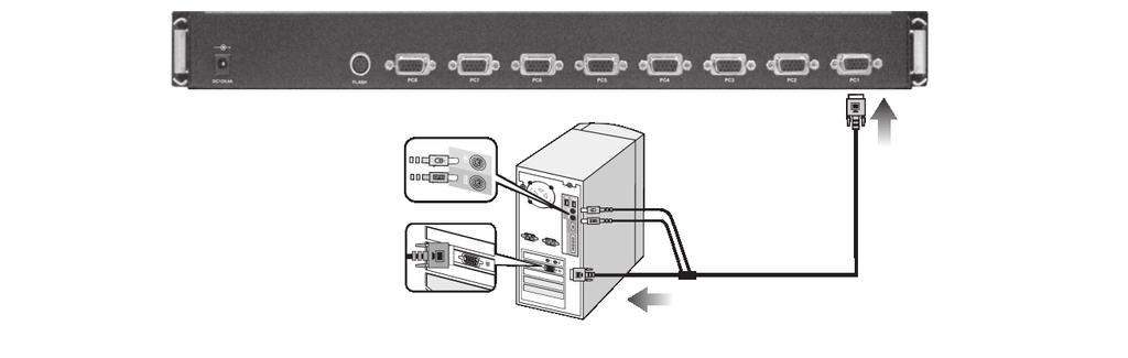
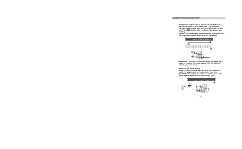
14 EM-815/817/1615/1617RX Connecting your External Mouse Connect your external mouse to the mouse port located on the front panel of the RX KVM switch. MULTIPLE STAGE INSTALLATION Cascading This section provides complete instructions for the hardware setup of installing cascaded computers. To control even more computers, up to 8 (EM-815RX/ 817RX) and 16 (EM-1615RX/1617RX) additional switches can be cascade from the CPU ports of the First Stage (Master) switch. The cascaded Switches that connect back to the First Stage switch are referred to as Second Stage switches (or BANKS) and assigned a location. For example; the Console keyboard, monitor and mouse connects to BANK 00 or the Master switch. As many as 128 / 256 computers can be controlled by a system administrator in a complete multi-bank installation. To set up a Multiple Stage Installation, do the following; 1. Power off all computers. 2. Using the all-in-one KVM Cable set (Part No. K15C6P). Take the male (HDDB-15pin) connector and plug it into the PC1 port indicated on the rear of the KVM Switch. Connect the other male VGA (HDDB-15) cable end to the console VGA port of the second stage switch. 3. Connect the PS/2 keyboard and mouse connectors of the KVM cable set to the second stage switch s console keyboard and mouse ports. Note : The above working diagram represents an EM-1610LS (16 port) KVM switch cascaded with the EM-815/17RX KVM switch. 14

15
16 EM-815/817/1615/1617RX 3. Power on all computers. 4. Perform a Manual Reset of the Master KVM switch by pressing the Port 1 and Port 2 manual push button selectors simultaneously for 2 seconds. All port LEDs of the Master switch will flash green for reset confirmation. Confirmation Procedure Once all computers are powered on, the switch emulates both mouse and keyboard signals on each port allowing your computer to boot normally without errors. To make sure your Cascade installation was successful, do the following: 1. Press [SCROLL LOCK] twice and enter your 4 digit port ID code. For example: if Cascading is successful, press [SCROLL LOCK], [SCROLL LOCK], 0101, then the monitor will show PC1 s screen. 2. Check to see that the keyboard, monitor, and mouse are working normally. Proceed to do this with all occupied ports to verify that all computers are connected and responding correctly. If you encounter an error, check your cable connections for that computer and reboot. 13
17 EM-815/817/1615/1617RX OPERATION Controlling your computers with the RX series couldn t be easier. The RX series allows you to access the computers using three simple methods: Hot Keys Manual Selectors OSD (On Screen Display) Menu PC Manual Selectors You can select any computer or access any Bank by using the PC selectors located at the top left of the console draw. Manual Selectors You can directly select any single computer or access any connected Bank by using direct-access PC selectors located at the top left of the KVM console. Each port switch has a corresponding LED for easy status monitoring. A Green LED indicates current port selection (Selected). A Red LED light indicates a port is not selected but the connected computer is powered and ready (Online). The RX series is also equipped with seven segment LCD display for BANK identification when Cascading. HOT KEYS Port Identification Each computer in a RX installation has a specific port ID. You can directly switch the KVM focus to any computer by entering the switch port number and the BANK number (for cascaded installations). Each is assigned a two digit numeric ID. Single Switch Installation The Port number (X) is a two digit number that identifies the port on the RX KVM switch that the computer is connected to. For example, a computer connected to Port 8 has the numeric ID of 08. Multiple Switch Installation (Cascading) The Port number (X) is a two digit number that identifies the port on the KVM switch that the computer is connected to. The BANK number (Y) is a two digit number that identifies the Switch s position in the cascade installation. (Note: the BANK number always precedes the Port number.) 14
18 EM-815/817/1615/1617RX For example, a computer connected to Port 8 of BANK 6 has the numeric ID of: 0608 Selecting the Active Port Directly switch the KVM focus to any computer by entering the Port number and / or the BANK number. Single Stage Installation ; Port number Port ID:08 Port ID:05 Port ID:01 For example ; To access a PC with the port ID 08 : Press [SCROLL LOCK], [SCROLL LOCK], 08. To access a PC with the port ID 05 : Press [SCROLL LOCK], [SCROLL LOCK], 05. Multiple Switch Installation Cascade ; Port number Bank00 Port ID:0008 Port ID:0006 Port ID:0004 Bank01 Port 6 Port ID:0106 Bank07 Port 8 Port ID:0708 Port 2 Port ID:0702 Note: The above working diagram represents an EM-1610LS(16 ports)kvm Switch cascade with the EM-815/817RX KVM Switch. For example ; To access a PC with the port ID 0008 : Press [SCROLL LOCK], [SCROLL LOCK], To access a PC with the port ID 0702: Press [SCROLL LOCK], [SCROLL LOCK],
19 EM-815/817/1615/1617RX Reset PC Name This function resets PC Name settings to default values. Quick View Scan Mode The Quick View Scan feature allows you to monitor the activity of the connected computers at regular intervals so that you can monitor the computer activity without having to take the trouble of switching yourself. This time interval can be changed as desired. Note: 1. The interval between these two keys should be no more than 0.5 seconds. Once the scanning begins, it continues until you press any key to exit Quick View Scan Mode. 2. A Port LED will flash indicating that the connected computer is under Auto Scan mode. Setting the Quick View Scan Time The scan time or the time the Switch spends on each port can be changed using either Hot Keys or OSD. Password Security Locking Server Access Administrators can set a unique password to restrict access to computers connected to the RX switch. Changing your Password To set a new password, do the following: 1. Invoke the Hot Key mode by pressing the [SCROLL LOCK] key twice within two seconds. 2. Key in [R] 3. Enter old password (up to 15 characters). 4. Enter the new password (up to 15 characters). 5. Re-enter the new password for confirmation. Hotkey Beeper Confrmation The beeper function can be turned on and off as desired using the following Hotkey sequence: 19
20 EM-815/817/1615/1617RX HOT KEY COMMANDS SUMMARY On-Screen Port Identification tag Previous active channel Next active channel Switch to Port X (X = 01-16) Switch to Port X on Bank Y (Y = 00-16) (cascading) Previous active bank Next active bank Switch to Master switch Enable OSD Mode Set OSD display time; 7 sec Set OSD display time; 15 sec Set OSD display time; 30 sec Set OSD display time; 60 sec Reset OSD menu Reset PC Name Quick View Scan mode Stop Quick View Scan mode Turn On / Off Beep confirmation (1 beep = ON, 2 beeps = OFF) Set Quick View Scan time; 7 sec Set Quick View Scan time; 15 sec Set Quick View Scan time; 30 sec Set Quick View Scan time; 60 sec Set Alternative Shift Hot Key Set Default Scroll Lock Hot Key Set Password Change Password Any key S Shift Shift S X Y Page Up Page Down Home X Space bar D 0 7 D 1 5 D 3 0 D 6 0 Delete Insert O B S 0 7 S 1 5 S 3 0 S 6 0 Shift P R Shift Enter Enter Note : 1.The [SCROLL LOCK] key must be pressed within 2 seconds. 2. The Shift key can be another Hot Key choice. 3. You will find that after the KVM unit switches to another computer, there is a mouse-keyboard delay of 1-2 seconds. This is normal and ensures re-synchronization of the console and connected computers. 17
21 EM-815/817/1615/1617RX OSD OPERATION The On Screen Display (OSD) is an intelligent menu system designed to help administrators set up and easily access and control a multiple server installation. The menu driven interface consists of a main Overview menu and an Administrative sub-menu from which users can perform multiple tasks from naming servers to configuring operations. The superimposed OSD overlay screen is generated by the Switch and does not affect your computers or software in any way. OSD Overview Menu The main On Screen Display (OSD) menu can be accessed by doing the following: 1. Press the [SCROLL LOCK] key twice followed by the Space bar. The OSD overlay screen appears. Note: When Hot plugging computer ports you must manually refresh (exit and re-enter) the OSD menu to display the new status information of the corresponding port. The OSD Overview Menu displays a list of connected computers, controls and function keys as well as symbols that refer to the status of each computer. 21
22 EM-815/817/1615/1617RX Navigation Use the following to navigate through the OSD menu: To escape from the OSD menu or sub-menu, press the [Esc] key. To move up and down through the screen list use the Up / Down arrows. Move the highlight bar to the desired location and press [Enter] to activate a port. OSD Heading NAME PWR PORT Description Port or server name that is designated by the user. (See OSD Functions in the next section under Port Naming). The symbol indicates that the computer connected to that port is powered on. If a computer is connected and powered on, but the OSD menu does not display a symbol, reset the Switch in order to re-detect the server. To reset the Switch press the Port 1 and Port 2 manual push button selectors simultaneously for 2 seconds An E Symbol displays when cascading computers. Lists the port identification numbers for all connected servers. The 2 digits (read left-to-right) consist of the BANK and PORT number respectively. To gain access to a computer move the highlight bar over a server in the name list and hit [Enter]. To gain BANK level access when cascading computers, move the highlight bar over a server in the name list and press [SCROLL LOCK] twice to display the BANK OSD. For example; a cascaded KVM switch connected to the Master switch Port 2 will show the preceding BANK numeral as 2. OSD Main Menu Functions This section provides details on the use of the following OSD functions; HOME-MASTER, UP/DOWN, SPACE-ADMIN, ENTER, INS and ESC. From the main OSD mode, the following OSD functions can be accessed: HOME-MASTER To return the KVM focus to the Master switch s first active port press [Home] from the keyboard. UP / DOWN To select any computer at the same KVM stage, move the highlight bar using the [Up] / [Down] arrow keys and press [Enter]. (e.g. Bank 01 Ports 01 to 16 / Bank 00 Ports 01 to 16) 22
23 EM-815/817/1615/1617RX Accessing computers using the OSD: To access computers of the Master Switch 1. Invoke the Hot key mode by pressing the [SCROLL LOCK] key twice within two seconds. 2. Key in [SPACE] 3. Move the highlight bar between 1 and Press [ENTER] to gain access to the computer shown with a symbol. (Note: the OSD display will be dismissed after [ENTER] is pressed.) To access computers of the Slave Switch 1. Invoke the Hot key mode by pressing the [SCROLL LOCK] key twice within two seconds. 2. Key in [SPACE] 3. In the OSD of the Master Switch, move the highlight bar to the cascaded port shown with an E symbol. 23

24 EM-815/817/1615/1617RX According to the previous OSD, port 1 of the Master Switch is cascaded. In order to access the Slave Switch, move the highlight bar to port 1 and press [ENTER] to access the slave switch. 4. Press [SCROLL LOCK] key twice within two seconds. 5. Key in [SPACE]. 6. Move the highlight bar from 1 to 8 to select the desired computer and press ENTER. Note: the RX series is designed for 2 levels of cascading only. Returning to the Master Switch Using OSD 1. Invoke the Hot key mode by pressing the [SCROLL LOCK] key twice within two seconds. 2. Key in [SPACE] 3. Key in [Home] Note: After switching back to the Master switch, port 1 of the Master switch is always the first to be shown. SPACE SPACE - ADMIN To access the Administration sub-menu press [SPACE], [SPACE] from the main OSD menu. (see next section for details). 24
![EM-815/817/1615/1617RX ENTER To confirm a selection and save the content input press [ENTER]. [ESC] To exit the current OSD menu press [ESC].](/docs-images/74/71298502/images/25-1.jpg "OSD Administration Sub-Menu This section provides details on configuring default Hot keys to setting up user password access. To access the Administration sub-menu complete the following: 1.")
25 EM-815/817/1615/1617RX ENTER To confirm a selection and save the content input press [ENTER]. [ESC] To exit the current OSD menu press [ESC]. OSD Administration Sub-Menu This section provides details on configuring default Hot keys to setting up user password access. To access the Administration sub-menu complete the following: 1. Press [SPACE], [SPACE] from the main OSD menu (see above). The OSD overlay screen appears. 22
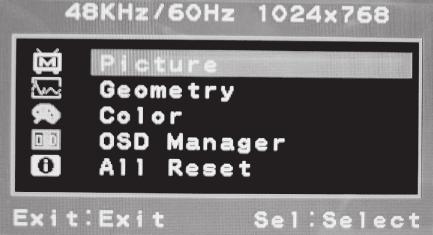
26 EM-815/817/1615/1617RX OSD Function CHANGE HOT KEYS CHANGE SCAN TIME CHANGE DISPLAY TIME FIRMWARE INFORMATION CHANGE PASSWORD RESET Description Changes the default Hot Key option (Scroll Lock <-> Shift). Quick View Scan allows users of large installations hands-free automatic scanning and viewing of all connected ports for a selected time interval. You may choose 7, 15, 30, or 60 seconds. Changes the amount of time the OSD menu is displayed on-screen and also specifies the amount of time the Port Identification tag displays on-screen after making a port selection. You may choose 7, 15, 30, or 60 seconds. Indicates version and make of your RX KVM sw itch. Modify and/or delete user passwords. Resets OSD function settings to default values (server names designated by the administrator are NOT affected). Perform an OSD Reset when Daisy Chaining or when keyboard / mouse inactivity is experienced. NOTE: Pressing [SCROLL LOCK], [SCROLL LOCK], [Delete] will reset the OSD to its factory default settings. FIRMWARE UPDATES Firmware upgrades enable your KVM switch to maintain consistent compatibility with the latest devices and computers. Firmware upgrades are free for the life of your RX KVM switch. Refer to the Windows flash upgrade instructions below for the latest upgrade software, information and support. To update the firmware, you will need the following items: 1. A separate computer running Windows 95/98/ME/2000 or XP. This computer must not be connected to the CPU ports on your KVM switch. 23

27 EM-815/817/1615/1617RX 2. An available serial port on the computer. 3. A custom serial cable (8 pin to RS232 9 pin). included in package. 4. Firmware update files available at customer support web site. Set Up To setup for the flash upgrade, do the following: 1. Open the firmware upgrade program by double clicking on the latest firmware file from customer support web site. 2. Use a computer that is not connected to your KVM computer ports. 3. Connect the power cord to the power jack of the KVM switch. Then plug the power cord into an available power outlet. 4. Using a serial cable (8 pin to RS232 9 pin) connect an available COM port on your computer. Take the other cable end and connect it to the FLASH port on the rear of the KVM switch. 24
28 EM- 3015/ 3017RM LCD CONTROL CONSOLE EM-3015/3017RM OVERVIEW The EM-3015RM/3017RM is a rackmounted control console designed for 19 rack systems. The EM-3015RM/3017RM is designed for the control and access of server farms or automation applications. The EM-3015RM/3017RM integrates a 15/17 inch color TFT LCD module, which supports up to XGA (1024 x 768 ) and 16.7M, 8 bit color. The new innovative design with heavy-duty steel housing and aluminum front brezel meets tough environmental standards. Whether it s in educational, government, or corporate sectors, the EM- 3015RM/3017RM provides network administrators and IT managers a stable management tool for server access and control. FEATURES Stable management tool 1U,19 design for universal setting 15 /17 color TFT-LCD module 3 Step rack mount installation Easy maintenance PACKAGE CONTENTS The complete EM-3015RM/3017RM package consists of: Item qty Remark EM-3015RM/3017RM 1 19 Rackmount LCD KVM console drawer Power Cord 1 Power Adapter 1 Bracket 2 User Manual 1 Combo Cable 1 25
29 EM- 3015/ 3017RM Check to make sure that the unit was not damaged during shipment. If you encounter a problem, contact your dealer. Please read this manual thoroughly. Follow the installation guide and operation procedures carefully to prevent any damage to the EM-3015RM/3017RM, and/ or any of the devices that connect to it. SPECIFICATIONS Display Area (mm) EM-3015RM EM-3017RM (H) x (V) (15.0"diagonal) (H) x (V) (17.0"diagonal) Pixel Pitch 0.297(H) x 0.297(V) 0.264(H) x 0.264(V) Number of Pixels 1024(H) x 768(V) Contrast Ratio (400 :1) (500:1) Display Color 262, M 2 Brightness( CD/m ) Input Signal Computer Port Connector Computer/ KVM Connections Keyboard and Key Pad Power Supply On-Screen Display Temperature 250(CD/m) RGB Analog Combo (15-pin, D-SUB) 106 key PS/2 keyboard with touch pad Auto, Brightness, Contrast, Horizontal, Vertical, Color, OSDHP, OSDVP OSD Time, Language, Recall, Exit 1 AC V 50-60Hz 0-40 deg.c in operating ; deg. C in storage Humidity 0 80% RH,non-condensing 1280(H) x 1024(V) 300(CD/m) Size & Weight x x mm, 10.3kg x x mm, 10.7kg Note: Specifications are subject to change without notice. 29
30
31 EM- 3015/ 3017RM HARDWARE REQUIREMENT Computer VGA,SVGA, MultiSync. (All in one combo 15-pin, D-SUB) KVM The KVM console must support the following specification. VGA,SVGA, MultiSync. (All in one combo 15-pin, D-SUB) Installing the Switch into a Server Rack Unlike other traditional rack mounted LCD KVM units the RM series requires only one person for installation. The RM series includes 2 adjustable sliding rack mount brackets for installation in 19-inch rack systems. The sliding brackets feature adjustable positions for rack depths of inches. Important Information Installing and or removing the Switch (module and chassis) improperly could void your warranty. I f you are uncertain what to do please contact Technical support. power cord into an AC power source. 3. Turn the EM-3015RM/3017RM on by pushing the Power-on button. HARDWARE INSTALLATION Please see page 8 for hardware installation. PANEL CONTRLOLS AND FUNCTIONS Please see page 9 for panel controls and functions. 28
32 EM- 1617RK LCD KVM SWITCH EM-1617RK Document Conventions This manual uses different formats to quickly identify information; [ ] Indicates keyboard selection. E.g., [Ctrl], 8 indicates you should press the Control key followed by the numeral 8. Sequenced keys appear with a comma between them: [Ctrl], [Ctrl] Bulleted information 1. Numbered lists designate sequenced instructions indicating important information. Italics Italics Represents text given in reference or as example. Important Information Please have the following information ready beforehand: Your current computer installation (operating system, configuration details, software etc.) Error messages, reports or other information that may assist our staff. INTRODUCTION Thank you for purchasing EM-1617RK rack-mount LCD KVM switch solution, the integrated 16-port Black CAT5 KVM switch. Designed for IT professionals, EM-1617RK leverages the power of existing server networks with minimal intrusion. Highly efficient: it allows centralized access and control of up to 256 computers (via Daisy-Chaining) from an integrated 1U console drawer; with built-in 17 LCD display, 16-port Black CAT5 KVM switch, keyboard and touchpad. The EM-1617RK is designed to deliver considerable return on investment; saving time, money and valuable server room real estate, it can be rack mounted at any user-height. EM-1617RK with integrated Black CAT5 KVM switch includes additional features such as: intelligent OSD (On Screen Display) menu, Hot Key switching, Auto sensing of cascade computers, Quick View scanning and Firmware upgrades. Whether it s in educational, government, or corporate sectors, the EM-1617RK provides network managers and IT managers a stable management tool for consolidated server access and control. 32
33 EM- 1617RK APPLICATIONS The EM-1617RK rack-mount console offers IT managers and MIS staff consolidated control of hundreds of computers* via a single integrated console. Applications include: ISPs / IDCs Data centers & server firms Test labs OVERVIEW OSD (On Screen Display) An intelligent menu system designed to easily access and control multiple servers. Hot Keys Hot keys allow you to use designated key commands to switch computers. Control multiple computers using a simple hot key sequence from your keyboard. Manual Port Selectors Push button selectors allow for convenient manual PC selection. LCD Bank Display The LCD Bank Display shows bank identification when daisy-chaining. Quick View Scan The Quick View Scan function allows you to automatically scan and monitor all computers - one by one, that are connected to your KORAT KVM switch. Video Resolution The 17 LCD monitor supports up to 1280 x Port LED Display Port LEDs allow for easy status monitoring of all connected computers. A lit Green LED indicates which computer the KVM console currently has control of. A Red LED indicates which computer is connected but not in use. Sliding (1U) console Drawer The entire LCD KVM console simply slides away into a compact 1U rack space when not in use. 33
34 EM- 1617RK FEATURES EM-1617RK Single-Rail Sliding console for any 1U(19 ) system rack Simple rack mount installation Lockable rail (screw type) on both ends to prevent unit from sliding out during transportation 17 LCD display, integrated console keyboard & touchpad in a 1U rack drawer RGB analog LCD display-up to 1280x1024 video resolution Multilanguage OSD (LCD control) Detachable console for easy repair or replacement Integrated 16 port CAT-5 KVM switch, yet maintaining the same 1U dimension Integrated CAT5 KVM switch allows connected computers to be placed up to 30m (100 feet) away Mix PS/2 and USB interfaces via simple KVM Cat5 Dongles between switch and computers Supports Windows 9x/ NT/ 2000/ ME/ XP/2003, NetWare5.0, Linux, Free BSD, Mac OSX, SUN New Rackmount Advantages One person installation saves valuable human resources and time Quick release rack-mount draw thumbscrews Adjustable rack slides for convenient positioning in server racks 34
35 EM- 1617RK PACKAGE CONTENTS Item qty EM-1617RK 1 Power Cord 1 Power Adapter 1 Bracket 2 User Manual 1 Power Adapter External Module 1 Please check to make sure that each item of the above list is included in your EM-1617RK package. Contact your dealer immediately if any item is missing or damaged in shipment. EQUIPMENT REQUIREMENTS Cables It is highly recommended that you use only our Cable sets. These cables offer the highest quality possible to ensure optimal data transmission. our KVM cables feature micro-cable construction and are molded together for a neat and organized setup. For EM-1617RK : the integrated Black Cat5 16-port KVM switch requires optional HAMSTER dongle per computer (USB dongle P/N: HAMSTER-U; PS/2 dongle P/N: HAMSTER-P). Please use CAT5E UTP or higher grade cable with lengths no more than 30M. For optimal performance, use CAT5E cables with similar lengths to connected PCs. Daisy-chain Cable: The daisy-chain cable uses standard DB25 to DB25 pin-to-pin configuration; if using a third party cable, please minimize the cable length to less than 30cm and use high quality, shielded cables. Power Supply AC V 50-60Hz Operating Systems Windows 9x/ NT/ 2000/ ME/ XP/2003, NetWare5.0, Linux, Free BSD, Mac OSX, SUN 32
36 EM- 1617RK Computers PS/2 Based: PS/2 Keyboard and Mouse, VGA Monitor USB Based: USB Keyboard and Mouse, VGA Monitor Note: EM-1617RK support PS/2 and USB based computers via optional HAMSTER-P and HAMSTER-U dongles, one dongle is required per computer. SPECIFICATIONS Note : Specifications are subject to change without notice. EM-1617RK DisplayArea(mm) Pixel Pitch (H) x (V) (17.0 diagonal) 0.264(H) x 0.264(V) Number of Pixels 1280(H) x 1024(V) Contrast Ratio (500:1) Display Color 16.2M Brightness(CD / m2 ) 300(CD/ m2 ) Input Signal Keyboard and Key Pad Power Supply LCD On-Screen Display Port Selection RGBAnalog 106 key PS/2 keyboard with touch pad AC V50-60Hz Auto, Brightness, Contrast, Horizontal, Vertical, Color, OSDHP, OSDVP OSD Time, Language, Recall, Exit. OSD/Hot Key/Push button Computer Port Connector RJ 45 Computer Connections(Direct) 16 (via optional Hamster CAT5 dongle, one unit required per PC) Computer Connections(Daisy chain) 256 Port LEDs 16 Port Switch Button 16 Temperature Humidity Housing Size & Weight Flash upgrade 0-40 deg.c in operting ; deg. C in storage 0 80% RH, non-condensing Metal x x 44mm / 10.3 kg Firmware upgradeable 33

37
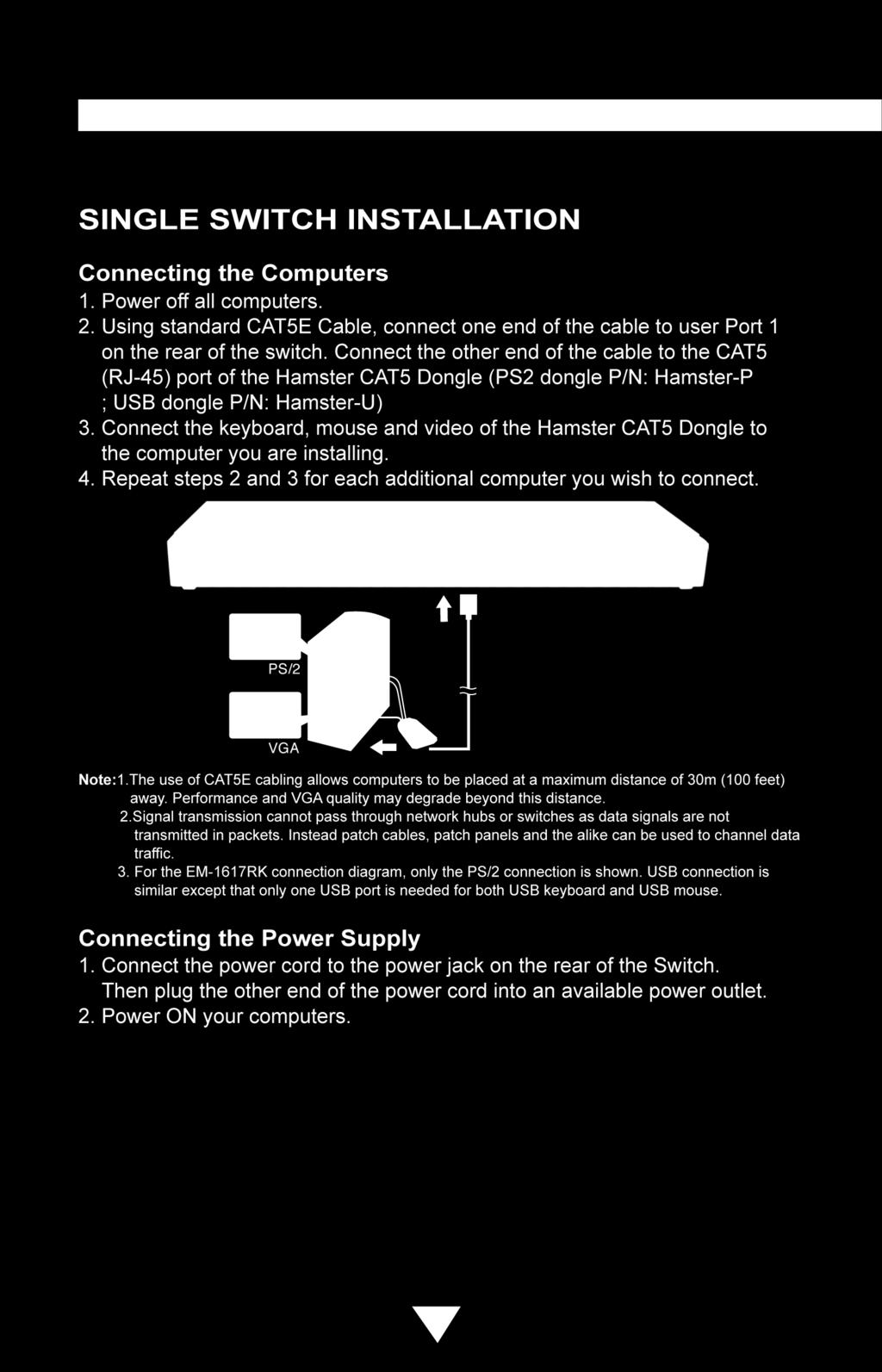
38 EM- 1617RK INSTALLATION Where to Place the Switch The enclosure of the EM-1617RK Switch is designed for standalone or rackmount configuration. The Switch is natively rack-mountable in a standard 1U (19 ) server rack. Rack-mount hardware is included with your switch for a sturdy rack installation. Cautions and Warnings Avoid placing cables near machines that create electrical noise such as fluorescent lighting, air conditioning equipment, etc. Important Information Before you begin, make sure that power to all the computers you will be connecting has been powered off. To prevent damage to your installation due to ground potential difference, make sure that all computers on the installation are properly grounded. Failure to follow these instructions can result in damage to computers and / or the Switch. Installing the Switch into a Server Rack Unlike other traditional rack mounted LCD KVM units the EM-1617RK series requires only one person for installation. The EM-1617RK includes 2 adjustable sliding rack mount brackets for installation in 19-inch rack systems. The sliding brackets feature adjustable positions for rack depths of inches. Important Information Installing and or removing the Switch (module and chassis) improperly could void your warranty. If you are uncertain what to do please contact our technical support. 35
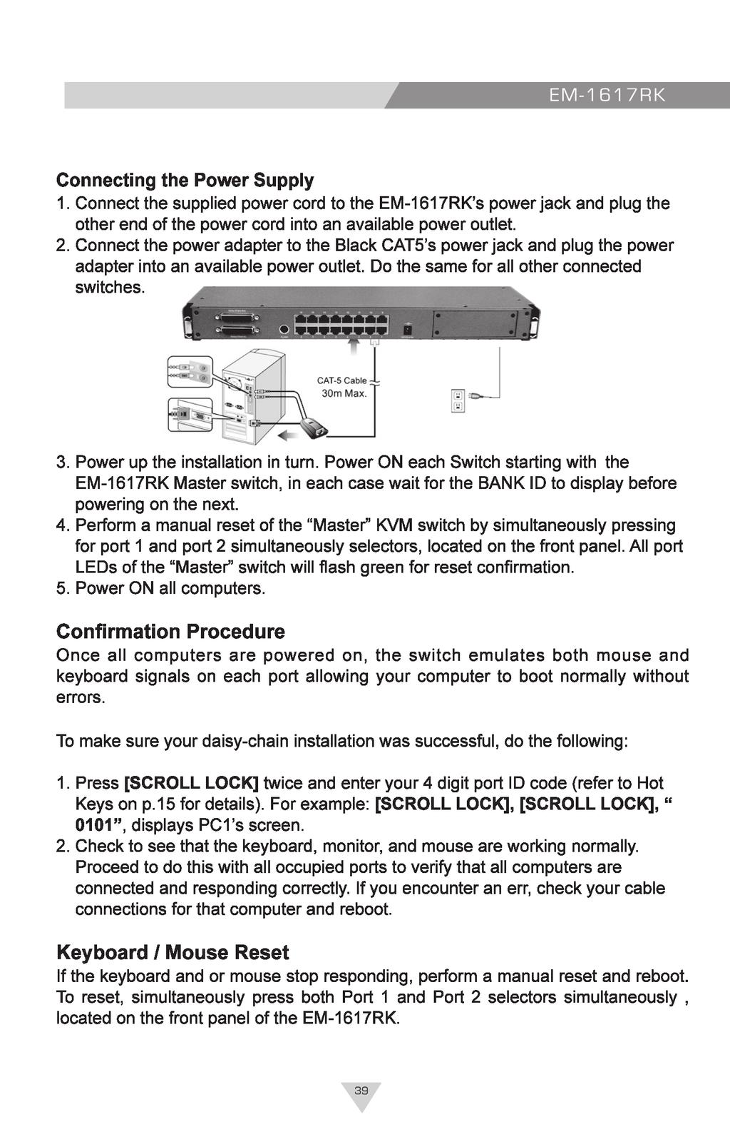
39 EM- 1617RK HARDWARE INSTALLATION Please see page 8 for hardware installation. Connecting the Power Adapter Attach the power cord to the back of the console and connect to a power source. Power Adapter External Module Installation (Optional) Please follow these simple steps to connect the power adapter with the external module 1.Loosen the screws and remove the back cover. 2.Install the power adapter to the external module and enwind the power cord as shown. 3.Install the power adapter external module to the back of the console. Fasten the screws on the side brackets. 4.Connect the power cord to the DC Power Input. Your 1617RK is now ready for use. PANEL CONTROLS AND FUNCTIONS Please see page 9 for panel controls and functions. 39
40
41
42
43 EM- 1617RK OPERATION Hot Plugging The EM-1617RK s integrated Black CAT5 features hot plugging where by computers can be added or removed without shutting down the Switch. When hot plugging console ports (keyboard, monitor, and mouse) if you experience a problem after removing and adding a new mouse, perform a manual reset by pressing Port 1 and 2 selectors of EM-1617RK s front panel. Should the problem continue after performing a system reset, restart the computer/s in question. Powering Down and Restarting Powering down the EM-1617RK and/or attached Switches will not affect the computers of your installation. On restarting the EM-1617RK and/or attached Switches, operator control is regained immediately. To replace a Switch, simply do the following: 1. Power down. 2. Remove the cables and plug them into the new switch. 3. Power On. Access and Control Controlling your computers with the EM-1617RK s integrated Black CAT5 KVM switch couldn t be easier. The Black CAT5 allows you to access the computers using three simple methods: n Manual Selectors n Hot Keys n OSD (On Screen Display) Menu Manual Switching You can directly select any single computer or access any connected Bank ( / ) by using the convenient direct-access selector located on the front panel of the EM-1617RK Rack Mount Console with integrated Black CAT5 KVM Switch. Each port switch has a corresponding LED for easy status monitoring. A Green LED indicates current port selection (Selected). A Red LED light indicates a port is not selected but the connected computer is powered and ready (Online). The EM-1617RK is also equipped with a seven segment LED display for BANK identification when daisy-chaining. 43

44
45


46 EM- 1617RK Hot Key Configuration Reset PC Name This function resets PC Name settings to default values. Quick View Scan Mode The Quick View Scan feature allows you to monitor the activity of the connected computers at regular intervals so that you can monitor the computer activity without having to take the trouble of switching yourself. This time interval can be changed as desired. Note: 1. The interval between these two keys should be no more than 0.5 seconds. Once the scanning begins, it continues until you press any key to exit Quick View Scan Mode. 2. A Port LED will flash indicating that the connected computer is under Auto Scan mode. Setting the Quick View Scan Time The scan time or the time the Switch spends on each port can be changed using either Hot Keys or OSD. Password Security Locking Server Access Administrators can set a unique password to restrict access to computers connected to the Black CAT5 switch. Changing your Password To change your password, do the following; 1. [SCROLL LOCK] key twice within two seconds. 2. Key in [R] 3. Enter old password (up to 6 characters). 4. Enter the new password (up to 6 characters). 5. Re-enter the new password for confirmation. Hotkey Beeper Confirmation The beeper function can be turned on and off as desired. 43
47 EM- 1617RK HOT KEY SUMMARY COMMANDS g Switch Ports g Switch Bank & Port g Switch Banks g Return to Master KVM g Set OSD Display Time g OSD Default Setting g Activate Password g Change Password g Enable OSD Menu g Enable Quick View Scan g Disable Quick View Scan g Set Quick View Scan g Time Turn ON/OFF Beeper g Change Default Hot Key S Any Key Y Page Up Home D Delete P R O S B H / X Page Down Space bar Note: 1. Where X = Port 01~16, Y= Bank 00~15 2. The [SCROLL LOCK] key must be pressed within 2 seconds. 3. The Shift key can be another Hot Key choice. 4. You will find that after the KVM unit switches to another computer, there is a mouse- keyboard delay of 1-2 seconds. This is normal and ensures re-synchronization of the console and connected computers. 44
48 EM- 1617RK Keyboard Emulation (Hamster-U ONLY) Sun Keyboard When the Right Control key (RCtrl) is used with combination keys (see below), a standard PS/2 (101/104) key keyboard can emulate the functions of a Sun keyboard. Please refer to the corresponding functions shown in the table below. Note: For the above Control key combinations, press and release the Right Control key ([Ctrl]), followed by the corresponding activation key. Mac Keyboard A compatible PS/2 (101/104) key keyboard can emulate the functions keys of a Mac keyboard. The table below shows the keybaord emulation mappings. Note: For the above Control key combinations, press and release the Right Control key ([Ctrl]),followed by the corresponding activation key. 45
49 EM- 1617RK OSD OPERATION The On Screen Display (OSD) is an intelligent menu system designed to help administrators set up and easily access and control a multiple server installation. The menu driven interface consists of a main Overview menu and an Administrative sub-menu from which users can perform multiple tasks from naming servers to configuring operations. The superimposed OSD overlay screen is generated by the Switch and does not affect your computers or software in any way. OSD Overview Menu The main On Screen Display (OSD) menu can be accessed by doing the following: 1. Press the [SCROLL LOCK] key twice followed by the Space Bar. The OSD overlay screen appears, as below: Note: When Hot plugging computer ports you must manually refresh (exit and re-enter) the OSD menu to display the new status information of the corresponding port. The OSD Overview Menu displays a list of connected computers, controls and function keys as well as symbols that refer to the status of each computer. 49
50 EM- 1617RK Navigation Use the following to navigate through the OSD menu: n To escape from the OSD menu or sub-menu, press the [Esc] key. n To move up and down through the screen list use the Up / Down arrows. n Move the highlight bar to the desired location and press [Enter] to activate a port OSD Main Menu Functions This section provides details on the use of the following OSD functions; HOME-MASTER, UP/DOWN, SPACE-ADMIN, ENTER, INS and ESC. From the main OSD mode, the following OSD functions can be accessed: HOME-MASTER To return the KVM focus to the Master switch s first active port press Home from the keyboard. UP / DOWN To select any computer at the same KVM level, move the highlight bar using the / arrow keys and press [Enter]. (Pg UP/Down) To scroll through the Previous/Next BANK screen list. (INS): RENAME Press the Insert key to name each computer by port (up to 15 characters). (ENTER) To confirm a selection and save the content input, press [ENTER]. 47
![EM- 1617RK Accessing Computers of the Master Switch 1. Press the [SCROLL LOCK] key twice followed by the Space Bar. 2.](/docs-images/74/71298502/images/51-0.jpg "Move the highlight bar (1-8 or 9-16) to a connected computer designated by the power symbol. 3. Press [ENTER] to access to the selected computer. Note: OSD display disappears after [ENTER] is pressed.")
51 EM- 1617RK Accessing Computers of the Master Switch 1. Press the [SCROLL LOCK] key twice followed by the Space Bar. 2. Move the highlight bar (1-8 or 9-16) to a connected computer designated by the power symbol. 3. Press [ENTER] to access to the selected computer. Note: OSD display disappears after [ENTER] is pressed. Accessing Daisy-chained Computers 1. Press the [SCROLL LOCK] key twice followed by the Space Bar. 2. Press [Page Up] / [Page Down] to access the required BANK. 3. Move the highlight bar to select a connected computer designated by the power symbol and press [ENTER]. Note: The Black CAT5 series is designed for 15 levels of daisy-chaining only. 48
52 EM- 1617RK (SPACE) (SPACE) - ADMIN To access the Administration sub-menu press [Space Bar], [Space Bar] from the main OSD menu. (See next section for details.) (ESC) To exit the current OSD menu, press [ESC]. OSD Administration Sub-Menu This section provides details on configuring default Hot keys to setting up user password access. To access the Administration sub-menu complete the following: 1. Press [Space Bar], [Space Bar] from the main OSD menu (see above). The OSD overlay screen appears. 49
53 EM- 1617RK OSD Function Description CHANGE HOT KEYS Changes the default HOT Key option (Scroll Lock <=> Shift) CHANGE SCAN TIME Quick View Scan allows users of large installations hands-free automatic scanning and viewing of all connected ports for a selected time interval. You may choose 7, 15, 30, or 60 seconds. CHANGE DISPLAY TIME Changes the amount of time the OSD menu is displayed on-screen and also specifies the amount after making a port selection. You may choose 7, 15, 30, or 60 seconds. CHANGe.paSSWORD Modify and/or delete user passwords (up to 6 characters) RESET Resets OSD function setting to default values (server names designated by the administrator are NOT affected). Perform an OSD Reset when Daisy-chaining or when keyboard / mouse inactivity is experienced. NOTE: Pressing [SCROLL LOCK], [SCROLL LOCK], [Delete] will reset the OSD to its factory default settings. 50
54 EM- 1617RK FIRMWARE UPDATES Firmware upgrades enable your KVM switch to maintain consistent compatibility with the latest devices and computers. Firmware upgrades are free for the life of your EM-1617RK s integrated Black CAT5 KVM switch. Refer to the Windows flash upgrade instructions below or visit us at for the latest upgrade software, information and support. To update the firmware, you will need the following items: 1. A separate computer running Windows 95/98/ME/2000 or XP. This computer must not be connected to the CPU ports on your KVM switch. 2. An available USB port on the computer. 3. A custom Flash cable (USB type A to mini-usb). Requires separate purchase. 4. Firmware update files available at Setting Up To setup for the flash upgrade, do the following: 1. Unplug all computers and or KVM switches connected to your EM-1617RK s integrated Black CAT5 KVM switch. 2. Use a computer that is not connected to your KVM computer ports. 3. Connect the power cord to the power jack of the KVM switch. Then plug the power cord into an available power outlet. 4. Using a Flash cable (USB type A to mini-usb)* to connect to an available USB port on your computer. Take the other cable end and connect it to the flash port (mini-usb) on the rear of the KVM switch. * flash cable sold separately 51

55 EM- 1617RK Starting the Upgrade 1. Execute the firmware upgrade program 2. The firmware upgrade Welcome screen appears. 3. Click Flash to perform the upgrade. 4. Click Close to Exit the firmware upgrade utility. 52
56 EM-815/817/1615/1617RX/3015/3017RM/1617RK FCC CERTIFICATIONS This equipment has been tested and found to comply with the limits for a Class B digital device, pursuant to Part 15 of the FCC Rules. These limits are designed to provide reasonable protection against harmful interference in a residential installation. This equipment generates uses and can radiate radio frequency energy and, if not installed and used in accordance with the instructions, may cause harmful interference to radio communications. However, there is no guarantee that interference will not occur in a particular installation. If this equipment does cause harmful interference to radio or television reception, which can be determined by turning the equipment off and on, the user is encouraged to try to correct the interference by one or more of the following measures: Reorient or relocate the receiving antenna. Increase the separation between the equipment and receiver. Connect the equipment into an outlet on a circuit different from that to which the receiver is connected. Consult the dealer or an experienced radio/tv technician for help. Shielded interface cables must be used in order to comply with emission limits. You are cautioned that changes or modifications not expressly approved by the party responsible for compliance could void your authority to operate the equipment. This device complies with Part 15 of the FCC rules. Operation is subject to the following two conditions: (1) This device may not cause harmful interference, and (2) This device must accept any interference received, including interference that may cause undesired operation. CE Mark Warning This is a Class B product. In a domestic environment, this product may cause radio interference, in which case the user may be required to take adequate measures. VCCI Warning 53
57
58 78D
8/16 Port LCD KVM Switch. JKP e/ e. JKP e/ e. LCD Control Console. JKP115e/117e. User Manual
 8/16 Port LCD KVM Switch JKP115-801e/117-801e JKP115-1601e/117-1601e LCD Control Console JKP115e/117e User Manual JKP115-801e/117-801e & JKP115-1601e/117-1601e LCD KVM SWITCH MANUAL CONVENTIONS...P1 TECHNICAL
DVI KVM Switch user manual Model
 DVI KVM Switch user manual Model 156066 INT-156066-UM-0808-01 introduction Thank you for purchasing the INTELLINET NETWORK SOLUTIONS DVI KVM Switch, Model 156066. This convenient device lets you control
SMK585 1U rackmount. With 8 Ports KVM Switch
 SMK585 1U rackmount Monitor Keyboard Drawer With 8 Ports KVM Switch TABLE OF CONTENTS Content FEATURES...1 BASIC SPECIFICATION...2 DISPLAY...2 PACKAGE CONTENTS...2 TECHNICAL SPECIFICATIONS...3 SYSTEM REQUIREMENT...3
Toll Free: Tel: Fax:
 Toll Free: 1-888-865-6888 Tel: 510-226-8368 Fax: 510-226-8968 Email: sales@rackmountmart.com LCD Drawer User Manual This manual, covering various aspects of the equipment such as installation, setup and
8-Port / 16-Port KVM SWITCH User s Manual
 8-Port / 16-Port KVM SWITCH User s Manual Version 1.0 1. Introduction The 8-Port/16-Port KVM Switch are high quality and durable systems that will allow you to control 8/16 host computers (or servers)
LevelOne. User Manual KVM-0831/KVM /16-Port Combo KVM Switch w/ Expansion Slot. Ver
 LevelOne KVM-0831/KVM-1631 8/16-Port Combo KVM Switch w/ Expansion Slot User Manual Ver. 1.0-0706 ii Safety FCC This equipment has been tested and found to comply with Part 15 of the FCC Rules. Operation
Refurbished 1U 19in Rackmount LCD Console with Integrated 8 Port KVM Switch
 Refurbished 1U 19in Rackmount LCD Console with Integrated 8 Port KVM Switch Product ID: RKCONS1908R The RKCONS1908R Refurbished 1U 19-inch Rack Mount LCD Console provides centralized control for servers
SYNERGY GLOBAL INC. Toll Free : Fax :
 SYNERGY GLOBAL INC Toll Free : 1-888-865-6888 Fax : 510-226-8968 Email : info@rackmountmart.com LCD1U15-03 series & LCD1U17-10 series User s manual 4-in-1 (KVM switch, Keyboard, LCD display, touch pad)
User s manual 19 1U RACKMOUNT CONTROL CENTER. Rack-KVM in-1 TABLE OF CONTENTS INTRODUCTION... (KVM switch, Keyboard, LCD display, touch pad)
") Rack-KVM9000 User s manual 4-in-1 (KVM switch, Keyboard, LCD display, touch pad) 19 1U RACKMOUNT CONTROL CENTER Rev 1.1 TABLE OF CONTENTS INTRODUCTION... FEATURES.... PACKAGE CONTENTS..... TECHNICAL SPECIFICATIONS...
Rack-KVM9000 User s manual 4-in-1 (KVM switch, Keyboard, LCD display, touch pad) 19 1U RACKMOUNT CONTROL CENTER Rev 1.1 TABLE OF CONTENTS INTRODUCTION... FEATURES.... PACKAGE CONTENTS..... TECHNICAL SPECIFICATIONS...
INTRODUCTION...1 FEATURES...1 PACKAGE CONTENTS... 1 TECHNICAL SPECIFICATIONS...2 SYSTEM REQUIREMENT..3 CABLE DIAGRAMS.3 PRODUCT DETAILS 4
 TABLE OF CONTENTS INTRODUCTION...1 FEATURES....1 PACKAGE CONTENTS... 1 TECHNICAL SPECIFICATIONS....2 SYSTEM REQUIREMENT..3 CABLE DIAGRAMS.3 PRODUCT DETAILS 4 HARDWARE INSTALLATION 5 USAGE 5 ON SCREEN DISPLAY
SMK520 / SMK580 / SMK590 RACK MOUNTABLE 1 / 8 / 16 PORT PS2 KVM SWITCH USER S MANUAL
 SMK520 / SMK580 / SMK590 RACK MOUNTABLE 1 / 8 / 16 PORT PS2 KVM SWITCH USER S MANUAL Rev 1.1 TABLE OF CONTENTS INTRODUCTION...1 FEATURES....1 PACKAGE CONTENTS..... 2 TECHNICAL SPECIFICATIONS...3 SYSTEM
Single Rail LCD Console With 8/ 16 ports KVM User s Manual
 Single Rail LCD Console With 8/ 16 ports KVM User s Manual Index 1. INTRODUCTION.2 1.1 OVERVIEW.... 2 1.2 FEATURES......2 2. SPECIFICATIONS.3 2.1 GENERAL.....3 2.2 PACKAGE CONTENTS.........4 3. DESCRIPTION
Your Rackmount Display Solution. 1U Keyboard / Monitor + 8 / 16 Ports. BHK Black Hawk Series USER S MANUAL. Ver.1
 Your Rackmount Display Solution 1U Keyboard / Monitor + 8 / 16 Ports BHK Black Hawk Series USER S MANUAL Ver.1 Content Specification....3 Rackmount Installation......4 Product Detail 5 On Screen Display.....6
SMK525 / SMK585 / SMK595
 SMK525 / SMK585 / SMK595 RACK MOUNTABLE 1 / 8 / 16 PORT PS2 KVM SWITCH USER S MANUAL Rev 1.2 TABLE OF CONTENTS INTRODUCTION...1 FEATURES....1 PACKAGE CONTENTS..... 2 TECHNICAL SPECIFICATIONS...3 SYSTEM
4 / 8 / 16 PORT PS2 KVM SWITCH USER S MANUAL
 STACKABLE 4 / 8 / 16 PORT PS2 KVM SWITCH USER S MANUAL PC / Mac / Sun Multi Platform Rev 1.1 TABLE OF CONTENTS INTRODUCTION...1 FEATURES....1 PACKAGE CONTENTS..... 2 TECHNICAL SPECIFICATIONS...3 SYSTEM
TABLE OF CONTENTS Chapter 1 Introduction... 3 Chapter 2 Installation... 7 Chapter 3 Operation... 15
 TABLE OF CONTENTS Chapter 1 Introduction... 3 1.1 Features... 3 1.2 Package Contents... 4 1.3 Technical Specifications... 5 Chapter 2 Installation... 7 2.1 System Requirements... 7 2.2 Cable Diagrams...
User s Manual 2005 All Right Reserved
 Wide Screen SMK 4 Series User s Manual 2005 All Right Reserved Table of Content SPECIFICATION....1 FEATURES... 2 TECHNICAL SPECIFICATIONS...3 SYSTEM REQUIREMENT..3 CABLE DIAGRAMS.4 HARDWARE INSTALLATION
1. BRIEF INTRODUCTION...
 -1- Table of contents 1. BRIEF INTRODUCTION... 3 2. PACKAGE INSIDE... 3 3. FEATURES. 3 4. SPECIFICATIONS. 4 5. INSTALLATION. 5 6. USAGE ( Hotkey Commands and OSD Operations ).. 9-2 - BRIEF INTRODUCTION
(DS / DS-14202)
") 8-Port / 16-Port USB and PS/2 Combo-KVM Switch User s Manual (DS-13202 / DS-14202) Index 1. INTRODUCTION... 4 2. SPECIFICATIONS... 5 3. SYSTEM REQUIREMENTS... 6 4. INSTALLATION... 6 4.1. FRONT VIEW...
8-Port / 16-Port USB and PS/2 Combo-KVM Switch User s Manual (DS-13202 / DS-14202) Index 1. INTRODUCTION... 4 2. SPECIFICATIONS... 5 3. SYSTEM REQUIREMENTS... 6 4. INSTALLATION... 6 4.1. FRONT VIEW...
4 Port KVM Switch. If anything is damaged or missing, contact your dealer.
 4 Port KVM Switch User Manual CS-84A Read this guide thoroughly and follow the installation and operation procedures carefully in order to prevent any damage to the units and/or any devices that connect
Venus Series Stand Alone & Modular Combo-free KVM Switch User Manual
 Venus Series Stand Alone & Modular Combo-free KVM Switch User Manual Rev 2.0 Venus Series User Manual Table of Contents Table of Contents... I 1. Introduction... 1 1.1 Features... 1 1.2 Package Contents...
USB KVM Switch USER MANUAL CS62US / CS64US
 USB KVM Switch USER MANUAL CS62US / CS64US EMC Information FEDERAL COMMUNICATIONS COMMISSION INTERFERENCE STATEMENT: This equipment has been tested and found to comply with the limits for a Class B digital
TWO-CONSOLE (One Local, One CAT5 Remote) 8 port / 16 port 19 RACK MOUNTABLE PS/2 KVM SWITCH USER S MANUAL
 8 port / 16 port 19 RACK MOUNTABLE PS/2 KVM SWITCH USER S MANUAL") TWO-CONSOLE (One Local, One CAT5 Remote) 8 port / 16 port 19 RACK MOUNTABLE PS/2 KVM SWITCH USER S MANUAL Rev 1.0 TABLE OF CONTENTS INTRODUCTION...1 FEATURES....2 PACKAGE CONTENTS..... 3 TECHNICAL SPECIFICATIONS...4
TWO-CONSOLE (One Local, One CAT5 Remote) 8 port / 16 port 19 RACK MOUNTABLE PS/2 KVM SWITCH USER S MANUAL Rev 1.0 TABLE OF CONTENTS INTRODUCTION...1 FEATURES....2 PACKAGE CONTENTS..... 3 TECHNICAL SPECIFICATIONS...4
AS-9104/08DA DVI KVM Switch User Manual
 KVM Discovery powered by Haitwin-Delphin Technologie GmbH, Kieselstraße 15, 41472 Neuss / Germany phone: 0049(0)2131/7421652 email: info@kvm-discovery.com AS-9104/08DA DVI KVM Switch User Manual Note This
User Manual. CV-401 / 801 / U Rackmount PS/2 KVM Switch
 User Manual CV-401 / 801 / 1601 1U Rackmount PS/2 KVM Switch 1. Table Of Content 1. Table of Content P.1 2. Introduction P.2 3. Features P.2 4. Package Content P.3 5. Optional Accessories P.4 6. Peripheral
Folding Rackmount Console
 Folding Rackmount Console 15 Folding LCD Rackmount Console 17 Folding LCD Rackmount Console 19 Folding LCD Rackmount Console RACKCONS1501 RACKCONS1701 RACKCONS1901 Instruction Manual Actual product may
2-Port / 4-Port COMBO FREE (USB&PS/2)
") 2-Port / 4-Port COMBO FREE (USB&PS/2) KVM SWITCH User s Manual Version 2.0 1. Introduction Thank you for your purchase of Combo Free KVM Switch! You now have a high quality, durable system that will enable
2-Port / 4-Port COMBO FREE (USB&PS/2) KVM SWITCH User s Manual Version 2.0 1. Introduction Thank you for your purchase of Combo Free KVM Switch! You now have a high quality, durable system that will enable
IC-1504 / IC-1508 / IC-1516
 LCD KVM SWITCH IC-1504 / IC-1508 / IC-1516 USER MANUAL - 1 - LCD MONITOR SPECIFICATIONS Size 15 inch Screen Type TFT Contrast 500:1 Brightness 250 cd/m 2 View Angle 110 Resolution 1024x768@75Hz Response
LCD Drawer User Manual
 LCD Drawer User Manual Part# RM-F117A-SD (16"-short depth) - 1 - This manual, covering various aspects of the equipment such as installation, setup and cascade, will help you make full use of this LCD
1+1 Console 8/16/32 ports Modularize CAT-5 KVM Switch (Console Free)
") 1+1 Console 8/16/32 ports Modularize CAT-5 KVM Switch (Console Free) (w/ Optional Add-on IP Module / CAT-5 Module) User s Manual C o n t e n t s 1. INTRODUCTION... 2 1.1 MAIN FEATURES... 3 1.2 PACKAGE
1+1 Console 8/16/32 ports Modularize CAT-5 KVM Switch (Console Free) (w/ Optional Add-on IP Module / CAT-5 Module) User s Manual C o n t e n t s 1. INTRODUCTION... 2 1.1 MAIN FEATURES... 3 1.2 PACKAGE
User's Manual. LCD KVM Console Rack Drawer. RoHS
 User's Manual LCD KVM Console Rack Drawer Features and functions may be added or changed after the manual was written. Please visit our website to download the latest version of manual for reference. RoHS
CD Console. Gemini 15 / 17 / 19. SUN Microsystems. Benefits
 CD Console Modular KVM Design Scalable solution UP to 32 ports Integrate 18 models of KVM switches in 1U form factor to optimize space limitation Multi-platform Support The LCD console support multi-platforms:
CD Console. Gemini 15 / 17 / 19 / 19W. SUN Microsystems. Benefits
 CD Console Modular KVM Design Scalable solution UP to 32 ports Integrate 18 models of KVM switches in 1U form factor to optimize space limitation Multi-platform Support The LCD console support multi-platforms:
CyberView User Manual
 CyberView User Manual RKP215-801 RKP217-801 RKP215-1601 RKP217-1601 2U Rackmount LCD monitor Keyboard drawer with KVM switch Version 2.0 20 March 2004 Table of Contents 1.0 General... 3 1.1 Unit Introduction...
8 / 16 port combo KVM Switch 1+1 Console 8 / 16 port combo KVM Switch User Manual
 8 / 16 port combo KVM Switch 1+1 Console 8 / 16 port combo KVM Switch User Manual V2.0 2007.4.25 C o n t e n t s 1. Introduction... 16H4 1.1 Back Panel... 4 1.2 Main Features... 17H5 1.3 Package Contents...
Folding Rackmount Console
 RACKCONS2001 Instruction Manual Folding Rackmount Console 1U 20.1 Folding LCD Rackmount Console - USB and PS/2 FCC Compliance Statement This equipment has been tested and found to comply with the limits
CE-1000M CAT5 Module User Manual
 CE-1000M CAT5 Module User Manual Rev 1.0 CE-1000M User Manual I Table of Contents Table of Contents... I 1. Introduction... 1 1.1 Feature... 2 1.2 R-Box Package Contents... 3 1.3 Technical Specifications...
User Manual CL
 User Manual CL-1200 Warning! This is a class A product. In a domestic environment this product may cause radio interference in which case the user may be required to take adequate measures. This equipment
LevelOne. User Manual KVM-0811 / KVM /16-Port PS2 KVM Switch
 LevelOne KVM-0811 / KVM-1611 8/16-Port PS2 KVM Switch User Manual Table of Contents 1. INTRODUCTION...1 FEATURES...1 PACKAGE CONTENT...2 SYSTEM REQUIREMENTS...2 TECHNICAL SPECIFICATIONS...3 FRONT PANEL...4
8/16-Port Enterprise KVM Switch
 User s Manual 8/16-Port Enterprise KVM Switch Model No.: SP218D/SP226D World Wide Web: www.micronet.com.tw ; www.micronet.info Certifications FCC This equipment has been tested and found to comply with
CAT.5 COMBO-KVM SWITCH 8-PORT/16-PORT
 CAT.5 COMBO-KVM SWITCH 8-PORT/16-PORT Quick Installation Guide DS-15202 / DS-16202 1. System Requirements Hardware Local Host side : The following equipment must be equipped with each computer or server
CS-64U. User Manual
 User Manual CS-64U Read this guide thoroughly and follow the installation and operation procedures carefully in order to prevent any damage to the units and/or any devices that connect to them. This package
User Manual. Rack Dual Rail CAT5 LCD KVM Console (8 Port /16 Port/24 Port /32 Port) User Manual
 User Manual") Rack Dual Rail CAT5 LCD KVM Console (8 Port /16 Port/24 Port /32 Port) User Manual www.szkinan.com @all right reserved Shenzhen Kinan Technology Co.,Ltd Printing date: 2015/05 Version: V3.0-1 - Contents
Rack Dual Rail CAT5 LCD KVM Console (8 Port /16 Port/24 Port /32 Port) User Manual www.szkinan.com @all right reserved Shenzhen Kinan Technology Co.,Ltd Printing date: 2015/05 Version: V3.0-1 - Contents
Folding Rackmount Console
 RACKCONV1701 RACKCONV1901 Instruction Manual Folding Rackmount Console 1U 17/19 Folding LCD Rackmount Console, USB - Value Series FCC Compliance Statement This equipment has been tested and found to comply
Rackmount LCD Console - 1U - 17in Screen - US Keyboard p
 Rackmount LCD Console - 1U - 17in Screen - US Keyboard - 1080p Product ID: RKCOND17HDEU This 1U LCD console offers a space-saving solution for managing and monitoring your DVI or VGA servers and KVM switches
1U 17" Rackmount LCD Console with Integrated 16 Port IP KVM Switch
 1U 17" Rackmount LCD Console with Integrated 16 Port IP KVM Switch Product ID: CABCONS1716I This 1U Rack Mount LCD KVM Console features an integrated 16 Port Multi-Platform IP KVM Switch module, 17in active
Sylphit-Duo DSK-Series. KVM Drawer (with integrated KVM switch)
") Sylphit-Duo DSK-Series KVM Drawer (with integrated KVM switch) User Guide Version 1.0 Technology Corporation Rackit Technology Corporation 274 Madison Avenue, New York, NY 10016 Tel: (212) 679-0050 Fax:
Sylphit-Duo DSK-Series KVM Drawer (with integrated KVM switch) User Guide Version 1.0 Technology Corporation Rackit Technology Corporation 274 Madison Avenue, New York, NY 10016 Tel: (212) 679-0050 Fax:
LCD Drawer User Manual
 LCD Drawer User Manual - 1 - This manual, covering various aspects of the equipment such as installation, setup and cascade, will help you make full use of this widescreen LCD KVM Drawer. Please read this
KVM-U4 & KVM-U8. Users Guide. 8 Port VGA KVM Switch. 4 Port VGA KVM Switch CUSTOMER SUPPORT INFORMATION
 KVM-U4 & KVM-U8 4 Port VGA KVM Switch 8 Port VGA KVM Switch Users Guide CUSTOMER SUPPORT INFORMATION UMA 1180, Rev 1.1 Order toll-free in the U.S. 800-959-6439 FREE technical support, Call 714-641-6607
Dual Rail AS-7100 & AS-9100 series LCD KVM User Manual
 KVM Discovery powered by Haitwin-Delphin Technologie GmbH, Kieselstraße 15, 41472 Neuss / Germany phone: 0049(0)2131/7421652 email: info@kvm-discovery.com Dual Rail AS-7100 & AS-9100 series LCD KVM User
CS-231. User Manual. Copyright ATEN International Co., Ltd. Manual Part No. PAPE G Printing Date: 11/2006
 User Manual CS-231 Read this guide thoroughly and follow the installation and operation procedures carefully in order to prevent any damage to the units and/or any devices that connect to them. This package
KVM I KVM I KVM-1160 USER'S MANUAL
 KVM-1 040 I KVM-1 080 I KVM-1160 USER'S MANUAL TABLE OF CONTENTS 1 FEATURES 1 PACKAGE CONTENTS 1 TECHNICAL SPECIFICATIONS 2 SYSTEM REQUIREMENT 3 CABLE DIAGRAMS 4 PRODUCT DETAILS 4 HARDWARE INSTALLATION
16-SLOT IN-BAND MANAGEMENT CHASSIS
 FCM-CHS2-XX 16-SLOT IN-BAND MANAGEMENT CHASSIS User's Guide. Version 1.6 FCC Warning This equipment has been tested and found to comply with the limits for a Class A digital device, pursuant to Part 15
8 ports/16 ports USB/PS/2 Combo-KVM Switch
 8 ports/16 ports USB/PS/2 Combo-KVM Switch Manual DS-23200-2 DS-23300-2 PRODUCT MODEL LIST Model DS-23200-2 DS-23300-2 Specification 8 input (USB & PS/2), 1 output (USB), Supporting cascade & hub. 16 input
LevelOne. KVM-0115/KVM / 17-inch LCD KVM Rack Console. User Manual. Version
 LevelOne KVM-0115/KVM-0117 15 / 17-inch LCD KVM Rack Console User Manual Version 1.0-1305 1 SAFETY INSTRUCTIONS 1. Please read these safety instructions carefully. 2. Please keep this User Manual for later
1U 17in 1080p LCD Rack Console with Front USB Hub
 1U 17in 1080p LCD Rack Console with Front USB Hub RACKCONS17HD RKCONS17HDxx *actual product may vary from photos DE: Bedienungsanleitung - de.startech.com FR: Guide de l'utilisateur - fr.startech.com ES:
8/16/32 Ports CAT5 LCD KVM
 8/16/32 Ports CAT5 LCD KVM User Manual - V1.0 Use for product models of followings, KVM-1708COMBO-N KVM-1716COMBO-N KVM-1732COMBO-N KVM-1908COMBO-N KVM-1916COMBO-N KVM-1932COMBO-N NORCO S.E.A. PTE LTD
ComboCAT Port KVM Switch. User Guide. Rev 0.9
 ComboCAT 8-16- 32-Port KVM Switch User Guide Rev 0.9 Technology Corporation Rackit Technology Corporation 271 Madison Avenue, New York, NY 10016 Tel: (212) 679-0050 Fax: (212) 679-0040 1. 8 0 0. 6 3 6.
Rackmount Console quick install guide
 Rackmount Console KVM Switch quick install guide Model 501620 INT-501620-QIG-0408-01 INTRODUCTION Thank you for purchasing the INTELLINET NETWORK SOLUTIONS Rackmount Console KVM Switch, Model 501620 (15
Daisy Chain KVM Console KVM-17CZ User Manual
 Daisy Chain KVM Console KVM-17CZ www.szkinan.com @all right reserved Shenzhen Kinan Technology Co.,Ltd Printing date: 2014/10 Version: V3.0 Product Description KVM-17CZ is a console integrates keyboard,
3-Port COMBO FREE DVI KVM SWITCH. ( with Audio ) User s Manual. Revision 2.0
 User s Manual. Revision 2.0") 3-Port COMBO FREE DVI KVM SWITCH ( with Audio ) User s Manual Revision 2.0 1. Introduction Thank you for your purchase of Combo Free DVI KVM Switch! You now have a high quality, durable system that will
3-Port COMBO FREE DVI KVM SWITCH ( with Audio ) User s Manual Revision 2.0 1. Introduction Thank you for your purchase of Combo Free DVI KVM Switch! You now have a high quality, durable system that will
If anything is damaged or missing, contact your dealer.
 User Manual CS-64A Read this guide thoroughly and follow the installation and operation procedures carefully in order to prevent any damage to the unit and/or any devices that connect to it. This package
User Manual. 8/16-Port USB PS/2 Combo KVMP Switch GCS1808/GCS1716. PART NO. M1102-a/M1074-a. 1
 User Manual 8/16-Port USB PS/2 Combo KVMP Switch GCS1808/GCS1716 PART NO. M1102-a/M1074-a 1 www.iogear.com Package Contents 1 x 8/16-Port USB PS/2 Combo KVMP Switch 1 x PS/2 KVM Cable 1 x USB KVM Cable
8 Port Rackmount USB VGA KVM Switch w/ Audio (Audio Cables Included) StarTech ID: SV831DUSBAU
 StarTech ID: SV831DUSBAU") 8 Port Rackmount USB VGA KVM Switch w/ Audio (Audio Cables Included) StarTech ID: SV831DUSBAU The SV831DUSBAU 8 Port Rack Mount USB VGA KVM Switch (with Audio Cables Included) allows you to control up
8 Port Rackmount USB VGA KVM Switch w/ Audio (Audio Cables Included) StarTech ID: SV831DUSBAU The SV831DUSBAU 8 Port Rack Mount USB VGA KVM Switch (with Audio Cables Included) allows you to control up
LCD Drawer User Manual
 LCD Drawer User Manual AVP119-125VDC -T"ECH OMRANY i-tech Company LLC TOLL FREE: (888) 483-2418 EMAIL: info@itechlcd.com WEB: www.itechlcd.com This user manual generates various aspects of equipment including
LevelOne KVM User Manual. 17 Modularized KVM Console V
 LevelOne KVM-0217 17 Modularized KVM Console User Manual V1.0.0-0708 SAFETY INSTRUCTIONS 1. Please read these safety instructions carefully. 2. Please keep this User Manual for later reference. 3. Please
8-Port / 16-Port Rackmount user manual Models &
 8-Port / 16-Port Rackmount KVM Switch user manual Models 524629 & 524643 Shown: 16-Port, Model 524643 INT-524629/524643-UM-0309-01 524629_524643_01_man.indd 1 3/9/09 9:22:10 AM 524629_524643_01_man.indd
1RU 17.3 LCD Console Drawer with Integrated DVI KVM Switch - 8 Port User Manual
 1RU 17.3 LCD Console Drawer with Integrated DVI KVM Switch - 8 Port User Manual Contents 1. Introduction... 3 1.1 Main Features... 3 1.2 Package Contents... 3 1.3 LED Panel... 4 1.3.1 Port LED Indications...
If anything is damaged or missing, contact your dealer.
 User Manual CS-64U Read this guide thoroughly and follow the installation and operation procedures carefully in order to prevent any damage to the units and/or any devices that connect to them. This package
Rack Mount CAT5 KVM Switch (8Port/16 Port/32 Port) User Manual
 User Manual") Rack Mount CAT5 KVM Switch (8Port/16 Port/32 Port) User Manual www.szkinan.com @all right reserved Shenzhen Kinan Technology Co., Ltd Printing date:2015/04 Version: V2.0-1- Contents Overview... 3 Description...
Rack Mount CAT5 KVM Switch (8Port/16 Port/32 Port) User Manual www.szkinan.com @all right reserved Shenzhen Kinan Technology Co., Ltd Printing date:2015/04 Version: V2.0-1- Contents Overview... 3 Description...
USB 2.0 DVI KVM Switch USER MANUAL CS682
 USB 2.0 DVI KVM Switch USER MANUAL CS682 EMC Information FEDERAL COMMUNICATIONS COMMISSION INTERFERENCE STATEMENT: This equipment has been tested and found to comply with the limits for a Class B digital
CL Port PS/2-USB VGA Dual Rail LCD KVM Switch with Daisy-Chain Port and USB Peripheral Support
 CL5808 8-Port PS/2-USB VGA Dual Rail LCD KVM Switch with Daisy-Chain Port and USB Peripheral Support The CL5808 Slideaway Dual Rail LCD KVM Switch is a control unit that allows access to multiple computers
Table of Contents. Overview...2. Features...2. Packing List...3. Assembly...5. Installation...8. Front Panel...9
 Table of Contents INTRODUCTION...1 SERVERLINK LCD CONSOLE Overview...2 Features...2 Packing List...3 Assembly...5 Installation...8 Front Panel...9 Replaceable Keyboard and Touch Pad... 10 LCD Specification...
LCD Drawer User Manual
 LCD Drawer User Manual Screen Pivot Version - RM-/F21A-R/F24A-R - 1 - This manual, covering various aspects of the equipment such as installation, setup and cascade, will help you make full use of this
MasterConsole Digital (MCD and MCD-LED17 Series) User Guide
 User Guide") MasterConsole Digital (MCD and MCD-LED17 Series) User Guide Release 1.0.0 Copyright 2017 Raritan, Inc. MCD-0A-v1.0.0-E April 2017 255-20-0007-00 This document contains proprietary information that is protected
MasterConsole Digital (MCD and MCD-LED17 Series) User Guide Release 1.0.0 Copyright 2017 Raritan, Inc. MCD-0A-v1.0.0-E April 2017 255-20-0007-00 This document contains proprietary information that is protected
Introduction. Table of Content. Overview. Automatic Mouse Conversion. Introduction
 ----------------- Introduction Introduction Table of Content Overview......1 Features....2 Installations Console Connection....3 Computers Connection... 4 Initial Power-up....6 Operations Front Panel operation.........7
KVM SYSTEMS KVM SYSTEMS
 KVM SYSTEMS 7 LCD KVM Drawer Page 6-3 Analog KVM Switch with DB15 Ports Page 6-5 IP KVM Switch with DB15 Ports Page 6-7 IP KVM Switch with Cat 5/6 Ports Page 6-9 KVM Switch Accessories Page 6-12 KVM SYSTEMS
dedicated KVM switch and rackmount screen technology User Manual CV-801 PS/2 DB-15 KVM Designed and manufactured by Austin Hughes
 dedicated KVM switch and rackmount screen technology User Manual PS/2 DB-15 KVM Designed and manufactured by Austin Hughes 751 Legal Information First English printing, October 2002 Information in this
User Manual - KVM Rear Kit Version
 dedicated KVM switch and rackmount screen technology User Manual - KVM Rear Kit Version for LCD Console Drawer PS/2 DB-15 KVM - 801 back Designed and manufactured by Austin Hughes 751 Legal Information
SMK 920/980/990 (P) User Reference Manual
 User Reference Manual") SMK 920/980/990 (P) User Reference Manual Revision 1.8 LCD Keyboard Drawer Specification for SMK 920/980/990 (P) P/N: 82002-01054 1 Chassis External Chassis Industrial Metal Frame Display LCD 17, 19" Diagonal
SMK 920/980/990 (P) User Reference Manual Revision 1.8 LCD Keyboard Drawer Specification for SMK 920/980/990 (P) P/N: 82002-01054 1 Chassis External Chassis Industrial Metal Frame Display LCD 17, 19" Diagonal
WL-21701/21708/21716 User Reference Manual. Revision 1.3 (080717)
") WL-21701/21708/21716 User Reference Manual Revision 1.3 (080717) LCD Keyboard Drawer Specification for WL-21701/21708/21716 Chassis External Chassis Industrial Metal Frame Display LCD 17, 19" Diagonal
WL-21701/21708/21716 User Reference Manual Revision 1.3 (080717) LCD Keyboard Drawer Specification for WL-21701/21708/21716 Chassis External Chassis Industrial Metal Frame Display LCD 17, 19" Diagonal
User Manual LKS-CD17SR 17 LCD Single Rail Console Drawer with Modular KVM Switch
 User Manual LKS-CD17SR 17 LCD Single Rail Console Drawer with Modular KVM Switch LKS-CD19SR 19 LCD Single Rail Console Drawer with Modular KVM Switch Rev 2.0 Packing List ServerLink LKS-CD17SR / CD19SR
Unicorn 15 / 17 / 19 Single rail 15 / 17 / 19" LCD console with modular KVM switch
 Unicorn 15 / 17 / 19 Single rail 15 / 17 / 19" LCD console with modular Unicorn series Single Rail consoles offer industrial level input solution to optimize your space utilization by controlling your
Rack Mount LCD KVM Assembly. Installer/User Guide
 Rack Mount LCD KVM Assembly Installer/User Guide Rack Mount LCD KVM Assembly Installer/User Guide Avocent, the Avocent logo and The Power of Being There are registered trademarks of Avocent Corporation
Table of Contents. ServerLink Eco KVM Rack Drawer. Overview... 1 Features... 2 Configurations... 3 Front Panel Control... 5
 Table of Contents Introduction Overview... 1 Features... 2 Configurations... 3 Front Panel Control... 5 Installation Rack Cabinet... 6 Device Connection for LKS-1017E... 8 Device Connection for LKS-8017E
USB VGA KVM Console Extender w/ Serial & Audio Over Cat5 UTP ft
 USB VGA KVM Console Extender w/ Serial & Audio Over Cat5 UTP - 1000 ft Product ID: SV565UTPUSA The SV565UTPUSA USB VGA KVM Console Extender w/ Serial & Audio Over Cat5 UTP (1000 ft) lets you control a
CD Console. Unicorn 15 / 17 / 19 / 19W. SUN Microsystems. Benefits
 Num CD Console Modular KVM Design Scalable solution UP to 3 ports Integrate 18 models of KVM switches in 1U form factor to optimize space limitation Multi-platform Support The LCD console support multi-platforms:
The OmniCube User Manual
 The OmniCube User Manual P72462 F1D094 Introduction Thank you for purchasing the Belkin Components OmniCube KVM (Keyboard Video Mouse) switch. Controlling four PCs from one keyboard, mouse and monitor
Table of Contents INTRODUCTION STREAMLINE CONSOLE. Overview..1. Overview..2. Features...2. Packing List..3. Assembly.. 4 ~ 6.
 Table of Contents INTRODUCTION Overview..1 STREAMLINE CONSOLE Overview..2 Features...2 Packing List..3 Assembly.. 4 ~ 6 Installation 7 Front Panel.. 8 Specifications.9 Please read this manual thoroughly
User Manual. Combo DB-15 2-console KVM. Combo DB-15 2-console KVM. Combo DB-15 KVM. dedicated KVM switch and rackmount screen technology
 dedicated KVM switch and rackmount screen technology User Manual Combo DB-15 2-console KVM KVM-IP8 / KVM-IP16 Combo DB-15 2-console KVM KVM-08R / KVM-16R Combo DB-15 KVM KVM-S8 / KVM-S16 751 Legal Information
BHK117Ue/BHK119Ue User Reference Manual l-tech COMPANY
 BHK117Ue/BHK119Ue User Reference Manual l-tech COMPANY i-tech Company LLC TOLL FREE: (888) 483-2418 EMAIL: info@itechlcd.com WEB: www.itechlcd.com LCD Keyboard Drawer Specification for BHK117Ue/BHK119L)e
User Manual. VGA KVM Switch, PS2 and USB. GCS1722/GCS1724 PART NO. M1258 / M
 User Manual VGA KVM Switch, PS2 and USB GCS1722/GCS1724 PART NO. M1258 / M1259 www.iogear.com - 1 - 2013 IOGEAR. All Rights Reserved. PKG-M1258 / M1259 IOGEAR, the IOGEAR logo, are trademarks or registered
User Manual LKS-CD17DR LKS-CD19DR. 17 LCD Dual Rail Console Drawer with Modular KVM Switch. 19 LCD Dual Rail Console Drawer with Modular KVM Switch
 User Manual LKS-CD17DR 17 LCD Dual Rail Console Drawer with Modular KVM Switch LKS-CD19DR 19 LCD Dual Rail Console Drawer with Modular KVM Switch Rev 2.0 Packing List The complete LKS-CD17DR / CD19DR dual
KVM08KD. KVM Switch with Keyboard Mouse Build In
 KVM08KD KVM Switch with Keyboard Mouse Build In COPYRIGHT This document is a copyright of the original manufacturer, 2000. The original manufacturer reserves the right to make improvements to the product(s)
Installation A B. Install each bracket using screws provided shown in Figure 1. Fix the KVM into the rack
 Installation screw A: M3.2 x 4.5 mm A B Cy r be Vie w screw B: M4 x 10 mm Install each bracket using screws provided shown in Figure 1. Fix the KVM into the rack Figure 1. Installing the bracket to the
DVI Desktop 4-Port Audio-Combo-KVM Switch
 DVI Desktop 4-Port Audio-Combo-KVM Switch User s Manual (DS-12800) Index 1 INTRODUCTION... 2 1.1 FEATURES... 2 1.2 PHYSICAL DIAGRAM... 3 1.3 PACKAGE CONTENTS... 3 2 SPECIFICATIONS... 4 2.1 GENERAL... 4
Industrial Rack-mount LCD KVM Drawer. User Manual. 8 -Port KVM Drawer 16-Port KVM Drawer
 Industrial Rack-mount LCD KVM Drawer User Manual 8 -Port KVM Drawer 16-Port KVM Drawer TABLE OF CONTENTS 4 Packing Contents 4 Safety Instructions 6 Introduction 6 Feature 8 Specification 10 Panel Description
N331 Wireless Mini Optical Mouse User s Guide
 N331 Wireless Mini Optical Mouse User s Guide Mouse 1. Left mouse button 2. Right mouse button 3. Scroll wheel 4. Charge port 5. Battery cover 6. Receiver storage compartment 7. Battery cover release button
If anything is damaged or missing, contact your dealer.
 User Manual CS-102 CS-122 Read this guide thoroughly and follow the installation and operation procedures carefully in order to prevent any damage to the unit and/or any devices that connect to it. This
Toll Free: Tel: Fax:
 Toll Free: 1-888-865-6888 Tel: 510-226-8368 Fax: 510-226-8968 Email: sales@rackmountmart.com User Manual LCDK 1070 DVI-D KVM Legal Information First English printing, October 2002 Information in this document