SDM-8AO. Expansion Module 8 analog outputs. Manufactured for
|
|
|
- Terence Hunter
- 6 years ago
- Views:
Transcription

1 Version Manufactured for


2 Thank you for choosing our product. This manual will help you with proper support and proper operation of the device. The information contained in this manual have been prepared with utmost care by our professionals and serve as a description of the product without incurring any liability for the purposes of commercial law. This information does not release you from the obligation of own judgment and verification. We reserve the right to change product specifications without notice. Please read the instructions carefully and follow the recommendations contained therein. WARNING! Failure to follow instructions can result in equipment damage or impede the use of the hardware or software. Version z 17
3 1. Safety rules Before first use, refer to this manual Before first use, make sure that all cables are connected properly Please ensure proper working conditions, according to the device specifications (eg: supply voltage, temperature, maximum power consumption) Before making any modifications to wiring connections, turn off the power supply 2. Module Features 2.1. Purpose and description of the module The SDM-8AO module has a set of 8 analog outputs that could work as a current output (0-20mA or 4-20mA) or as a voltage output (0-10V). Setting the output curent or voltage value is done via RS485 (Modbus protocol), so you can easily integrate the module with popular PLCs, HMI or PC equipped with the appropriate adapter. This module is connected to the RS485 bus with twisted-pair wire. Communication is via MODBUS RTU or MODBUS ASCII. The use of 32-bit ARM core processor provides fast processing and quick communication. The baud rate is configurable from 2400 to The module is designed for mounting on a DIN rail in accordance with DIN EN The module is equipped with a set of LEDs used to indicate the status of inputs and outputs useful for diagnostic purposes and helping to find errors. Module configuration is done via USB by using a dedicated computer program. You can also change the parameters using the MODBUS protocol. Version z 17
4 2.2. Technical Specifications Power Supply Outputs Temperature Connectors Size Voltage Maximum Current * VDC; 10-28VAC DC: 52 24VDC AC: 62 24VAC Maximum power consumption DC: 1,25W; AC: 1,5VA No of outputs 8 Voltage output Current output Current output Measurement resolution ADC processing time Work Storage Power Supply Communication Outputs Configuration Height Length Width 0V do 10V ( resolution 1.5mV) 0mA do 20mA ( resolution 5μA) 4mA do 20mA (value in 1000 steps) (resolution 16μA) 12 bits 16ms / channel -10 C C -40 C C 2 pins 3 pins 2x 10 pins Mini USB 110 mm 62 mm 88 mm Interface RS485 Up to 128 devices * Maximum current with active Modbus transmission, all inputs connected and all output active Version z 17
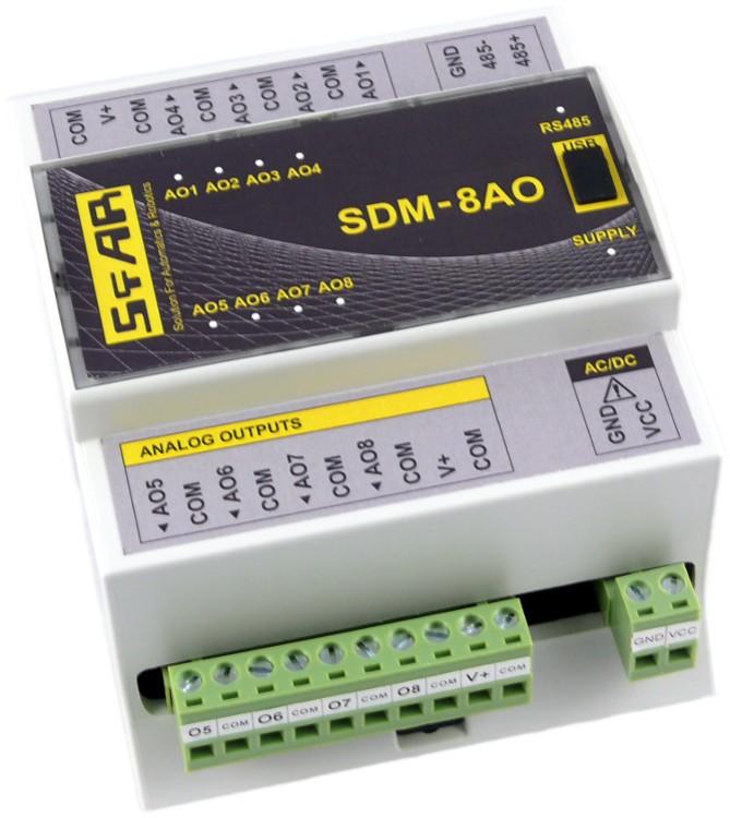
5 2.3. Dimensions of the product Look and dimensions of the module are shown below. The module is mounted directly to the rail in the DIN industry standard. Power connectors, communication and IOs are at the bottom and top of the module. USB connector configuration and indicators located on the front of the module , Version z 17
6 3. Communication configuration 3.1. Grounding and shielding In most cases, IO modules will be installed in an enclosure along with other devices which generate electromagnetic radiation. Examples of these devices are relays and contactors, transformers, motor controllers etc. This electromagnetic radiation can induce electrical noise into both power and signal lines, as well as direct radiation into the module causing negative effects on the system. Appropriate grounding, shielding and other protective steps should be taken at the installation stage to prevent these effects. These protective steps include control cabinet grounding, module grounding, cable shield grounding, protective elements for electromagnetic switching devices, correct wiring as well as consideration of cable types and their cross sections Network Termination Transmission line effects often present a problem on data communication networks. These problems include reflections and signal attenuation. To eliminate the presence of reflections from the end of the cable, the cable must be terminated at both ends with a resistor across the line equal to its characteristic impedance. Both ends must be terminated since the direction of propagation is bidirectional. In the case of an RS485 twisted pair cable this termination is typically 120 Ω Setting Module Address in RS485 Modbus Network The following table shows how to set switch to determine the address of the module. The module address is set with the switches in the range of 0 to 127. Addresses From 128 to 255 can by set via RS485 or USB. Switch Address SW1 +1 SW2 +2 SW3 +4 SW4 +8 SW5 +16 SW6 +32 SW7 +64 Ex. if switches 1, 3 and 5 are on than module addres is: Address = = 21 Version z 17
7 3.4. Types of Modbus Registers There are 4 types of variables available in the module Typ e Beginning address Variable Digital Outputs Digital Inputs Input Registers Output Registers Access Bit Read & Write Bit Read Registered Read Registered Read & Write Modbus Command 1, 5, , 6, Communication settings The data stored in the modules memory are in 16-bit registers. Access to registers is via MODBUS RTU or MODBUS ASCII Default settings You can restore the default configuration by the switch SW8 (see Restore the default configuration) Baud rate Parity Data bits 8 Stop bits 1 Reply Delay [ms] 0 Modbus Type Restore the default configuration To restore the default configuration: turn off the power turn on the switch SW8 turn on the power when power and communication LED start blinking alternately than turn off the switch SW8 Caution! After restoring the default configuration all values stored in the registers will be cleared as well. No RTU Version z 17
8 Configuration registers Modbus Dec Hex Name Values x02 Baud rate x04 Parity x03 Stop Bits LSB x03 Data Bits MSB other value * 10 0 none 1 odd 2 even 3 always 1 4 always 0 1 one stop bit 2 two stop bits 7 7 data bits 8 8 data bits x05 Response delay Time in ms x06 Modbus Mode 0 RTU 1 ASCII Version z 17
9 4. Switches ON Switch Function Description 1 Module address +1 2 Module address +2 3 Module address +4 4 Module address +8 5 Module address Module address Module address Restoring default settings Setting module address from 0 to 127 Restoring default settings (see Restore the default configuration). Version z 17
 as in the picture below. Version 1.0-16.05.")
10 5. Front panel removing To remove the panel and gain access to the switch, you must pry open the panel using a thin tool (eg a small screwdriver) as in the picture below. Version z 17
11 6. Indicators Output 1 4 state Communication ON mini USB configuration connector Output 5 8 state Power supply Indicator Power supply Communication Outputs state Description LED indicates that the module is correctly powered. The LED lights up when the unit received the correct packet and sends the answer. LED indicates that the output is on. Version z 17
12 7. Module Connection POWER SUPPLY SHIELD Voltage output* Current output* * Each of outputs can be configured as a voltage output or a current output POWER SUPPLY Version z 17


13 8. Setting output mode SDM-8AO Each of outputs can be configured as a voltage outputs or a current outputs. To change the operating mode in addition to configuration changes by using the program or via RS485, also set the jumpers inside the module as shown below. Jumper Description Current output (default) Voltage output 9. Opening the housing 1. Remove the clip by pressing it and moving toward the center of the housing 2. Separate the housing gently tilting the clamps using a thin tool. Version z 17
14 10. Modules Registers Registered access Modbus Dec Hex Register Name Access Description x00 Version/Type Read Version and Type of the device x01 Switches Read Switches state x02 Baud rate Read & Write RS485 baud rate x03 Stop Bits & Data Bits Read & Write No of Stop bits & Data Bits x04 Parity Read & Write Parity bit x05 Response Delay Read & Write Response delay in ms x06 Modbus Mode Read & Write Modbus Mode (ASCII or RTU) x08 Watchdog Read & Write Watchdog x20 Received packets LSB Read & Write x21 Received packets MSB Read & Write x22 Incorrect packets LSB Read & Write x23 Incorrect packets MSB Read & Write x24 Sent packets LSB Read & Write x25 Sent packets MSB Read & Write No of received packets No of received packets with error No of sent packets x32 Outputs Read Bit is set if value x34 Analog output 1 Read & Write x35 Analog output 2 Read & Write x36 Analog output 3 Read & Write x37 Analog output 4 Read & Write x38 Analog output 5 Read & Write x39 Analog output 6 Read & Write x3A Analog output 7 Read & Write x3B Analog output 8 Read & Write x3C Default output 1 value Read & Write x3D Default output 2 value Read & Write x3E Default output 3 value Read & Write x3F Default output 4 value Read & Write x40 Default output 5 value Read & Write x41 Default output 6 value Read & Write x42 Default output 7 value Read & Write x43 Default output 8 value Read & Write Value of analog output: in mv for voltage output (max 10240) in μa for current output 0-20mA (max 20480) in for current output 4-20mA (max 1000) Default value of output set when power is on or when watchdog reset occurs Version z 17
15 Modbus Dec Hex Register Name Access Description x44 Output 1 setting Read & Write Setting of output mode: x45 Output 2 setting Read & Write x46 Output 3 setting Read & Write x47 Output 4 setting Read & Write x48 Output 5 setting Read & Write x49 Output 6 setting Read & Write x4A Output 7 setting Read & Write x4B Output 8 setting Read & Write 0 output disable 1 voltage output 2 current output 0-20mA 3 current output 4-20mA Caution! For the change to take effect, you must also set the jumper inside the module Bit access Modbus Address Dec Address Hex Address Register name Access x320 Output 1 Read x321 Output 2 Read x322 Output 3 Read x323 Output 4 Read x324 Output 5 Read x325 Output 6 Read x326 Output 7 Read x327 Output 8 Read Description If voltage or current is greater than 0 then according bit is set. Version z 17


16 11. Configuration software Modbus Configurator is software that is designed to set the module registers responsible for communication over Modbus network as well as to read and write the current value of other registers of the module. This program can be a convenient way to test the system as well as to observe real-time changes in the registers. Communication with the module is done via the USB cable. The module does not require any drivers. USB PC Configurator is a universal program, whereby it is possible to configure all available modules. Version z 17


17 Table of content 1. Safety rules Module Features Purpose and description of the module Technical Specifications Dimensions of the product Communication configuration Grounding and shielding Network Termination Setting Module Address in RS485 Modbus Network Types of Modbus Registers Communication settings Default settings Restore the default configuration Configuration registers Switches Front panel removing Indicators Module Connection Setting output mode Opening the housing Modules Registers Registered access Bit access Configuration software...16 Manufactured for: Aspar s.c. ul. Kapitańska Gdynia POLAND ampero@ampero.eu tel ; Version z 17
18 Output No Current output (default) Voltage output
RS485 MODBUS Module 8AO
 Version 1.3 12/02/2013 Manufactured for Thank you for choosing our product. This manual will help you with proper support and proper operation of the device. The information contained in this manual have
SDM-6RO. Expansion Module 6 relay outputs. Manufactured for
 Version 1.0 5.02.2014 Manufactured for Thank you for choosing our product. This manual will help you with proper support and proper operation of the device. The information contained in this manual have
RS485 MODBUS Module 6RO
 Version 2.0 12/02/2013 Manufactured for Thank you for choosing our product. This manual will help you with proper support and proper operation of the device. The information contained in this manual have
RS 485 Mini Modbus 1AO
 RS 485 Mini Modbus 1AO Version 1.0 14/08/2014 Manufactured for Thank you for choosing our product. This manual will help you with proper support and proper operation of the device. The information contained
SDM-8I8O. Expansion Module 8 digital inputs, 8 digital outputs. Manufactured for
 Version 1.2 20.01.2014 Manufactured for Thank you for choosing our product. This manual will help you with proper support and proper operation of the device. The information contained in this manual have
RS485 MODBUS Module 16I-M
 Version 2.0 12/02/2013 Manufactured for Thank you for choosing our product. This manual will help you with proper support and proper operation of the device. The information contained in this manual have
RS485 MODBUS Module 8I8O
 Expansion Module 8 digital inputs, 8 digital outputs Version 2.2 12/01/2014 Manufactured for Thank you for choosing our product. This manual will help you with proper support and proper operation of the
RS485 MODBUS Module 8I8RO
 Expansion Module 8 digital inputs, 8 relay outputs Version 1.0 3.12.2014 Manufactured for Thank you for choosing our product. This manual will help you with proper support and proper operation of the device.
RS485 IO Slim Module MOD-ETH
 Expansion Module gateway Modbus TCP Version 1.0 01.12.2015 Manufactured for Thank you for choosing our product. This manual will help you with proper support and proper operation of the device. The information
isma-b-mg-ip User Manual Global Control 5 Sp. z o.o. Poland, Warsaw
 isma-b-mg-ip User Manual Global Control 5 Sp. z o.o. Poland, Warsaw www.gc5.pl Table of content 1 Introduction... 4 1.1 Revision history... 5 1.2 Safety rules... 5 1.3 Technical specifications... 6 1.4
isma-b-fcu FCU Hardware User Manual Global Control 5 Sp. z o.o. Warsaw, Poland
 isma-b-fcu User Manual FCU Hardware Global Control 5 Sp. z o.o. Warsaw, Poland www.gc5.pl Table of contents 1 Introduction 3 1.1 Document change log 3 1.2 Safety rules 3 1.3 Technical specifications 4
NetBiter I/O Extender User Manual
 User Manual Part no. 0920-9999-009 IntelliCom Innovation AB Pilefeltsgatan 73 SE-302 50 Halmstad SWEDEN Phone +46 35 17 29 90 Fax +46 35 17 29 09 email info@intellicom.se www www.intellicom.se Revision
Real Time Clock with Temperature Sensor and RS485/Modbus Comunications
 Real Time Clock with Temperature Sensor and RS485/Modbus Comunications April 29, 2014 Power 8 20 VDC @ less than 100 MA. Battery connect jumper RS485 Bus Load Jumpers Model: RTC-TI2C Page 1 of 6 Features:
Intech Micro 2300-RO4 analogue input station MODBUS RTU slave application supplementary manual.
 Intech Micro 2300-RO4 analogue input station MODBUS RTU slave application supplementary manual. MODBUS supplementary manual to the 2300-RO4 Installation Guide. The 2300 series stations are designed to
ASTAT XB/XBm Remote Operator
 ASTAT XB/XBm Remote Operator User Manual 1 Introduction 1.1 Important User Information Observe all necessary safety precautions when controlling the soft starter remotely. Alert personnel that machinery
Soft Starter Remote Operator. Section 1.0 Introduction 1.1 Important user information General Manual description...2.
 Section 1.0 Introduction 1.1 Important user information... 2 1.2 General... 2 1.3 Manual description...2 Contents Section 2.0 Specification 2.1 General technical data...3 2.2 Dimensions...3 Section 3.0
R1M-GH THERMOCOUPLE & DC INPUT MODULE MODEL. Remote I/O R1M Series. (16 points)
") Remote I/O R1M Series THERMOCOUPLE & DC INPUT MODULE (16 points) MODEL MODEL & SUFFIX CODE SELECTION R1MGH2T MODEL Modbus protocol I/O TYPE GH2 : Thermocouple or DC input, 16 points FIELD TERMINAL TYPE
Remote I/O R1M Series THERMOCOUPLE & DC INPUT MODULE (16 points) MODEL MODEL & SUFFIX CODE SELECTION R1MGH2T MODEL Modbus protocol I/O TYPE GH2 : Thermocouple or DC input, 16 points FIELD TERMINAL TYPE
Intech Micro 2300-A8VI analogue input station MODBUS RTU slave application supplementary manual.
 Intech Micro 2300-A8VI analogue input station MODBUS RTU slave application supplementary manual. MODBUS supplementary manual to the 2300-A8VI Installation Guide. The 2300 series stations are designed to
MU110-6U. Analog output module 6 channel. User guide
 MU110-6U Analog output module 6 channel User guide MU110-6U_2016.12_0221_EN All rights reserved Subject to technical changes and misprints akytec GmbH Vahrenwalder Str. 269 A 30179 Hannover Тел.: +49 (0)
Intech Micro 2300-RTD6 analogue input station MODBUS RTU slave application supplementary manual.
 Intech Micro 2300-RTD6 analogue input station MODBUS RTU slave application supplementary manual. MODBUS supplementary manual to the 2300-RTD6 Installation Guide. The 2300 series stations are designed to
MOD-MUX MODBUS TCP I/O PRODUCTS
 MOD-MUX MODBUS TCP I/O PRODUCTS Catalog and Design Guide P.O.Box 24 Stanfield 3613 SOUTH AFRICA Tel: +27 (031) 7028033 Fax: +27 (031) 7028041 Email: proconel@proconel.com Web: www.proconel.com 22/09/2009
VPGate Manual PROFIBUS to serial
 VPGate Manual PROFIBUS to serial Important information Purpose of the Manual This user manual provides information how to work with the VPGate PROFIBUS to serial. Document Updates You can obtain constantly
SmartMod DC Digital Input Module HE359DIM610 12/24VDC Negative Logic
 MAN0842-02 DIM610 PAGE 1 of 6 SmartMod DC Digital Input Module HE359DIM610 12/24VDC Negative Logic 1 SPECIFICATIONS Number of Channels Input Ranges DIM610 12 PLC Update Rate 12/24 VDC Terminal Type DIM610
3 CH Analog Output module / CANopen
 3 CH Analog Output module / CANopen Power Supply 1..4 Vdc, 19..28 Vac Isolation 1,5 kvac (5 way) Accuracy,5% A/D resolution 14 bit Channels 3 Voltage range 1 V Current range..2, 4..2 ma RPDO < 2 ms (-1%
Expansion Module HZS 541-1S
 Expansion Module HZS 541-1S 12.10.2015 Page 1 System Description The external HZS 541-1S expansion module provides users of biomass heating systems with additional 230 V AC relay outputs, analog inputs
SIC184 Manual Stepper motor servo controller
 SIC184 Manual Stepper motor servo controller P.P.H. WObit E.K.J. Ober s.c. 62-045 Pniewy, Dęborzyce 16 tel.+48 61 22 27 410, fax.+48 61 22 27 439 e-mail: wobit@wobit.com.pl www.wobit.com.pl Contains 1.Safety
DCC-8 DIGITAL TO EIGHT CURRENT LOOP CONVERTER OPERATING MANUAL
 DCC-8 DIGITAL TO EIGHT CURRENT LOOP CONVERTER OPERATING MANUAL 1 TABLE OF CONTENTS 1. MOUNTING INSTRUCTIONS 1.1 Standard DIN Rail mounting 1.2 Screw Mounting 2. FUSE REPLACEMENT 3. ASSEMBLING THE UNIT
XT-9100 Technical Bulletin
 System 9100 Technical Manual 636.4 Technical Bulletins Section Technical Bulletin Issue Date 0896 XT-9100 Technical Bulletin XT-9100 Extension Module/XP-910x Expansion Modules Page 3 Introduction 3 SX
Energy Management Modular DC Energy analyzer Type VMU-E and VMU-X
 Energy Management Modular DC Energy analyzer Type VMU-E and VMU-X Modular solution based on the combination of two units: VMU-E analysis unit and VMU-X universal power supply and RS485 communication unit.
PGR-3200 MANUAL INSULATION MONITOR
 Tel: +1-800-832-3873 E-mail: techline@littelfuse.com www.littelfuse.com PGR-3200 MANUAL INSULATION MONITOR REVISION 3-E-040918 Copyright 2018 by Littelfuse, Inc. All rights reserved. Document Number: PM-1025-EN
ProfiPro Distributed PROFIBUS I/O Modules User Manual
 ProfiPro Distributed PROFIBUS I/O Modules User Manual 15/03/2012 V1.0 22/195 Prospect Highway Seven Hills 2147 NSW Australia Tel: +61 (02) 96248376 Fax: +61 (02) 96208709 Email: proconel@proconel.com Web:
Message Runner KP3H. Text Display. Small messages on your machine. Compact DIN 36 x 72 profile. Green and orange character display.
 Message Runner KP3H Text Small messages on your machine This small and compact display is extremely well-suited for indicating a variety of short messages. Compact DIN 36 x 7 profile The compact DIN 36
SC2004MBS 20x4 Characters MODBUS RTU Slave LCD
 SC004MBS 0x4 Characters MODBUS RTU Slave SC004MBS is a MODBUS slave device that receives data from a Master MODBUS device and display them on the panel. The is 0 x 4 characters in size and each character
EE870 Modular CO 2 Transmitter
 EE870 Modular CO 2 Transmitter Manual BA_EE870_e // v1.5 // Technische Änderungen vorbehalten E+E Elektronik Ges.m.b.H. doesn't accept warranty and liability claims neither upon this publication nor in
KTA-250 Anemometer Alarm Card
 Connects to Davis Instruments DS7911 Anemometer Monitor both the wind speed and direction Interface to PLCs using the Modbus protocol Communicate via RS232 or 2-wire RS485 Interface to PLCs/Instruments
Submittal Data Sheet WAGO Node for itm
 The WAGO Node integrates ancillary equipment into the Intelligent Touch Manager (itm) DCM601A71 with the use of DI, DO, AI and AO signals. It provides monitoring and control of non-daikin equipment via
MVS RAIL ELECTRONIC FAN SPEED CONTROLLER. Mounting and operating instructions
 DIN RAIL ELECTRONIC FAN SPEED Mounting and operating instructions Table of contents SAFETY AND PRECAUTIONS 3 PRODUCT DESCRIPTION 4 ARTICLE CODES 4 INTENDED AREA OF USE 4 TECHNICAL DATA 4 STANDARDS 5 WIRING
Process displays For current and voltage
 Features Voltage input TRMS-AC/DC up to 600 V Current input AC/DC 1 A, 5 A and shunt (precision resistor) 60 or 100 mv With 2 or 4 limits Display range can be linearised Min, Max, Hold functions 4 20 ma
MODEL CIO-EN MODBUS/TCP, MODBUS/RTU I/O MODULE
 INSTALLATION INSTRUCTIONS Revision B1 Rapid City, SD, USA, 05/2009 MODEL CIO-EN MODBUS/TCP, MODBUS/RTU I/O MODULE BE SURE POWER IS DISCONNECTED PRIOR TO INSTALLATION! FOLLOW NATIONAL, STATE AND LOCAL CODES.
SSI-1016H Specifications and Operation Manual
 SSI-1016H Specifications and Operation Manual Warning: Product specifications and dimensions are subject to change without prior notice. MTS Sensors Technology Corporation 194-0211 737 Aihara-machi, Machida
MODEL: R2K-1 SEN TRONIC AG. R2K Series
 1 MODEL: R2K-1 R2K Series /RS-485 CONVERTER Functions & Features Bidirectional converter between and RS-485 used when connecting Modbus RS-485 devices to a PC CE marking Standard: Conforms to, EIA Transmission
MODBUS RTU MODULE INSTRUCTIONS. for use with WSIQ2/WSE
 INSTRUCTIONS MODBUS RTU MODULE for use with WSIQ2/WSE WorldWide Electric Corporation Phone: 1-8-88-2131 Fax: 1-8-711-1616 www.worldwideelectric.net Product Compatibility This communications module is suitable
Copyright: December 2017 Nidec Issue: E
 General Information The manufacturer accepts no liability for any consequences resulting from inappropriate, negligent or incorrect installation or adjustment of the optional parameters of the equipment
DL-10. User Manual. RS-485 Remote Temperature and Humidity. English Ver. 1.0, Jul. 2017
 DL-10 User Manual RS-485 Remote Temperature and Humidity English Ver. 1.0, Jul. 2017 WARRANTY All products manufactured by ICP DAS are warranted against defective materials for a period of one year from
Carbon Monoxide Sensor - ModBus
 Introduction The CO Sensor uses an electrochemical sensor to monitor CO level in a range of 0 to 500 ppm and communicates via an RS-485 network configured for ModBus protocol. Before Installation Read
IB ST 24 AO 4/EF. INTERBUS-ST analog output module, 4 outputs, 0-10 V, ±10 V, 0-20 ma, 4-20 ma. Data sheet. 1 Description
 INTERBUS-ST analog output module, 4 outputs, 0-10 V, ±10 V, 0-20 ma, 4-20 ma Data sheet 105597_en_01 PHOENIX CONTACT 2014-10-24 1 Description The module is designed for use within an ST station. It is
Temp-485-Pt100. A temperature sensor (Pt100 or Pt1000) communicating over the RS-485 bus with a simple communication protocol
 communicating over the RS-485 bus with a simple communication protocol") Temp-485-Pt100 A temperature sensor (Pt100 or Pt1000) communicating over the RS-485 bus with a simple communication protocol Temp-485-Pt100 Box version [600 113] Temp-485-Pt100 Cable version [600 114]
Temp-485-Pt100 A temperature sensor (Pt100 or Pt1000) communicating over the RS-485 bus with a simple communication protocol Temp-485-Pt100 Box version [600 113] Temp-485-Pt100 Cable version [600 114]
Measuring transducers MI4x0 series Programmable transducers for RTD sensors MI450
 Measuring transducers MI4x0 series Programmable transducers for RTD sensors MI450 o Measuring of resistance of RTD sensors (Pt100, Pt1000, Ni100, Cu10,...) o Accuracy class up to: 0.5 o Programmable input
MODEL: R1M-D1. PC Recorders R1M Series. SPECIFICATIONS OF OPTION: Q COATING (For the detail, refer to M-System's web site.)
") PC Recorders R1M Series PC RECORDER (contact output, 32 points) Functions & Features Industrial recorder on PC 32-point open collector outputs Easy system expansion via Modbus RTU Recorded data exportable
PC Recorders R1M Series PC RECORDER (contact output, 32 points) Functions & Features Industrial recorder on PC 32-point open collector outputs Easy system expansion via Modbus RTU Recorded data exportable
Serial Data DIN Fiber Link System
 USER GUIDE RLH Industries, Inc. The leader in rugged fiber optic technology. U-120 2017A-0420 DIN Fiber Link System COMPACT, RUGGED & TEMPERATURE HARDENED Introduction The DIN Fiber Link system transports
Energy Management Modular DC Energy analyzer Type VIM-E and VIM-X
 Energy Management Modular DC Energy analyzer Type VIM-E and VIM-X Modular solution based on the combination of two units: VIM-E analysis unit and VIM-X universal power supply and RS485 communication unit.
INSTALLATION MANUAL. LC 200 Electronic Overload Guard. Software versione PW0501 R 0.3
 INSTALLATION MANUAL LC 200 Electronic Overload Guard Software versione PW0501 R 0.3 CONTENTS MAIN FEATURES LC 200 TECHNICAL FEATURES Page 2 SYMBOLS Page 3 WARNINGS Page 3 IDENTIFICATION DATA PLATE Page
Serial Communication Converters & Adapters Instruction Manual
 Serial Communication Converters & Adapters Instruction Manual RS-232 to RS-422/485 Converter Isolated RS-232 to RS-422/485 Converter USB to RS-232 Converter USB to RS-422/485 Converter Isolated USB to
Warranty. Warning. Copyright. Contact Us
 M-6026U-32 16-channel Universal Input and 16-channel Universal Output Version: 1.0.0 Date: Dec. 2017 Edited by Horse Chien M-6026U-32 User Manual Version 1.0.0 Dec. 2017-1 - Warranty All products manufactured
SATEL I-LINK 100 MB I/O-converter User Guide, Version 1.1
 TABLE OF CONTENTS TABLE OF CONTENTS... 1 IMPORTANT NOTICE... 2 PRODUCT CONFORMITY... 3 WARRANTY AND SAFETY INSTRUCTIONS... 4 1 GENERAL... 5 1.1 SATEL I-LINK 100 MODBUS I/O- CONVERTER... 5 2 SPECIFICATIONS...
UNT1100 Series. Binary Output Jumpers AO2 AO1 AO3 AO4 AOCM AOCM AOCM AOCM AO1. AI Switches Job Information N2 Address. Ref N2+ N2- ADDR 0 = ALL OPEN
 1 2 8 4 AI6 R R Installation Bulletin UNT1100 Issue Date 0309 UNT1100 Series Introduction The Unitary (UNT) controller (UNT1100 Series) is a digital controller with applications for air handling units,
MODEL: R1M-P4. PC Recorders R1M Series. SPECIFICATIONS OF OPTION: Q COATING (For the detail, refer to M-System's web site.)
") PC Recorders Series PC RECORDER (4 totalized counter inputs, 8 contact inputs and outputs) Functions & Features Industrial recorder on PC Totalized counter inputs Counts stored in E 2 PROM Easy system
PC Recorders Series PC RECORDER (4 totalized counter inputs, 8 contact inputs and outputs) Functions & Features Industrial recorder on PC Totalized counter inputs Counts stored in E 2 PROM Easy system
DI-917MB/DI-918MB. Heavy-duty 1A solid-state relays provide dependable on/off control of industrial devices. Analog Output Module. Four Analog Outputs
 Multi-Channel Analog Output Modules DC Current or DC Voltage Outputs Discrete Outputs DI-917MB/DI-918MB Models DI-917MB: 4 current output channels DI-918MB: 4 voltage output channels Analog Output DI-917MB:
Product Specification for SAB-S-MODBUS
 SAB-S-MODBUS May 9, 2011 Product Specification for SAB-S-MODBUS The SAB-S-MODBUS is a two-channel module that measures single or multiple magnet transducer position and returns this information to a host
DT1102 V (PS) Fully Configurable Galvanic Isolator. Operating Instructions
 Fully Configurable Galvanic Isolator. Operating Instructions") (PS) Fully Configurable Galvanic Isolator Operating Instructions Contents 1. About this document...4 1.1. Function... 4 1.2. Target group... 4 1.3. Symbolism used... 4 2. For your safety...5 2.1. Authorized
(PS) Fully Configurable Galvanic Isolator Operating Instructions Contents 1. About this document...4 1.1. Function... 4 1.2. Target group... 4 1.3. Symbolism used... 4 2. For your safety...5 2.1. Authorized
IO Module User Manual
 IO Module User Manual 27/08/2014 V1.0 P.O.Box 164 Seven Hills 1730 NSW AUSTRALIA Tel: +61 2 96248376 Fax: +61 2 9620 8709 Email: proconel@proconel.com Web: www.proconel.com Disclaimer Procon Electronics
APPLICATION NOTE. OJ-DRHX Modbus protocol OJ DRHX A DRIVES PROGRAMME DEDICATED TO ROTARY HEAT EXCHANGERS /17 (OSH) 2017 OJ Electronics A/S
 2017 OJ Electronics A/S") APPLICATION NOTE OJ-DRHX Modbus protocol 67730 10/17 (OSH) 2017 OJ Electronics A/S OJ DRHX A DRIVES PROGRAMME DEDICATED TO ROTARY HEAT EXCHANGERS Introduction This protocol contains the Modbus addresses
APPLICATION NOTE OJ-DRHX Modbus protocol 67730 10/17 (OSH) 2017 OJ Electronics A/S OJ DRHX A DRIVES PROGRAMME DEDICATED TO ROTARY HEAT EXCHANGERS Introduction This protocol contains the Modbus addresses
It is the installer's responsibility to follow all instructions in this manual and to follow correct electrical practice.
 MCD Modbus Module Instructions Important User Information INSTALLATION INSTRUCTIONS: MCD MODBUS MODULE Order Code: 175G9000 1. Important User Information Observe all necessary safety precautions when controlling
The accessories described in this manual are of the highest quality, carefully designed and built in order to ensure excellent performance.
 INTRODUCTION Thank you for choosing our product. The accessories described in this manual are of the highest quality, carefully designed and built in order to ensure excellent performance. This manual
Manual and Protocol Description
 Communication Module MSR240 1 Manual and Protocol Description Overview The MSR240 Communication Module serves as an interface between a MSR210 or MSR211 Basic Module and a standard serial data communication
IFC 100 Supplementary instructions
 IFC 100 Supplementary instructions Signal converter for electromagnetic flowmeters Description of Modbus interface Electronic Revision: ER 3.0.xx Modbus version: 1.0.xx KROHNE CONTENTS IFC 100 1 Important
MODEL: R1M-A1. PC Recorders R1M Series. SPECIFICATIONS OF OPTION: Q COATING (For the detail, refer to M-System's web site.)
") PC Recorders R1M Series PC RECORDER (contact input, 32 points) Functions & Features Industrial recorder on PC 32-point dry contact inputs Easy system expansion via Modbus RTU Recorded data exportable to
PC Recorders R1M Series PC RECORDER (contact input, 32 points) Functions & Features Industrial recorder on PC 32-point dry contact inputs Easy system expansion via Modbus RTU Recorded data exportable to
Vorne Industries. Model 77/232 Serial Input Numeric 3" Display User's Manual
 Vorne Industries Model 77/232 Serial Input Numeric 3" Display User's Manual 1445 Industrial Drive Itasca, IL 60143-1849 (630) 875-3600 Telefax (630) 875-3609 Page 2 Model 77/232 Serial Input Numeric 3"
Dupline. Data Logger. Types G , G Product Description. Ordering Key G Type Selection. Input/Output Specifications
 Dupline Data Logger Types G 800 006, G 800 106 Product Description Programmable channel generator with optional built-in GSM Modem Event and time based data logging functions for digital, analog and counter
RS-485 I/O Modules: ADAM-4000
 RS-485 I/O Modules: ADAM-4000 23 ADAM-4000 Series Overview ADAM-4000 Series Remote Data Acquisition and Control Modules Overview 23-2 and Controller Module Selection Guide 23-4 I/O Module Selection Guide
Installation & Operation Guide
 Installation & Operation Guide (Shown with optional Override Board Cover) KMD-5831 Programmable Loop Controller PLC-28 Direct Digital Controller 902-019-04B 1 Introduction This section provides a brief
AD-8923-BCD. Remote Controller (BCD) INSTRUCTION MANUAL 1WMPD
 INSTRUCTION MANUAL 1WMPD") AD-8923-BCD Remote Controller (BCD) INSTRUCTION MANUAL 1WMPD4002137 2010 A&D Company, Limited. All rights reserved. No part of this publication may be reproduced, transmitted, transcribed, or translated
AD-8923-BCD Remote Controller (BCD) INSTRUCTION MANUAL 1WMPD4002137 2010 A&D Company, Limited. All rights reserved. No part of this publication may be reproduced, transmitted, transcribed, or translated
OTB1S0DM9LP I/O distributed module OTB - Modbus non isolated serial link m
 Characteristics I/O distributed module OTB - Modbus non isolated serial link - 0..10 m Complementary Topology Bus length Main Number of devices per segment 0...32 Data format Parity Discrete input voltage
Measurement Systems Datascan Installation and User Guide
 Measurement Systems Datascan Installation and User Guide Supplied By Contents Contents 1. INTRODUCTION... 1 1.1 GENERAL... 1 1.2 DATASCAN MODULE RANGE... 1 1.2.1 Measurement Processors... 1 1.2.2 Analog
UNIVERSAL TRANSDUCER AR594
 APAR - SALES OFFICE 05-090 Raszyn, ul. Gałczyńskiego 6, Poland Tel. +48 22 101-27-31, +48 22 853-49-30 E-mail: automatyka@apar.pl Website: www.apar.pl USER INSTRUCTION UNIVERSAL TRANSDUCER AR594 Version
mbc082 Bus Converter
 BUS CONVERTER RS485 TO 1-WIRE BUS mbc082 mbc082 Bus Converter Document. 10910, Revision - February 2007 2007 CMC Industrial Electronics Ltd. This page intentionally left blank. mbc082 Bus Converter Technical
GE Fanuc IC694ALG221. Rx3i PacSystem
 GE Fanuc IC694ALG221 http://www.pdfsupply.com/automation/ge-fanuc/rx3i-pacsystem/ic694alg221 Rx3i PacSystem Input module, analog 4 point current. IC694A IC694AL IC694ALG 919-535-3180 sales@pdfsupply.com
Millenium 3 logic controllers
 Millenium 3 logic controllers Type Part number Power supply Inputs Outputs With display Without display CD12 88970041 24 V c 8 digital (of which 4 are analogue) 4 x 8 A relays 88970042 24 V c 8 digital
TM3AI4 module TM3-4 analog inputs
 Characteristics module TM3-4 analog inputs Main Range of product Product or component type Range compatibility Analogue input number 4 Analogue input type Complementary Analogue input resolution Permissible
I-7520: RS-232 to RS-485. Input: RS-232 protocol Output:RS-485/RS-422 Speed: Self Tuner 'inside, auto switching baud rate, 300~ BPS
 I-7520 RS-232 to RS-485 Converter I-7510 RS-485 Repeater RS-232 RS-485 I-7000 SERIES Common Specifications Isolation voltage: 3000VDC Speed: 1200, 2400, 4800, 9600, 19200, 38400, 57600, 115000 Dual watchdog
USER MANUAL 2012 V1.1
 SMART MINI POWER SDM630 USER MANUAL 2012 V1.1-1 - Installation and Operation Instructions Important Safety Information is contained in the Maintenance section. Familiarise yourself with this information
ABB Drives. User s Manual Modbus Adapter Module FMBA-01
 ABB Drives User s Manual Modbus Adapter Module FMBA-01 Modbus Adapter Module FMBA-01 User s Manual 3AFE68586704 REV A EN EFFECTIVE: 27.06.2005 2005 ABB Oy. All Rights Reserved. 5 Safety instructions
INSTRUCTION SHEET. Eaton Logic Controller DeviceNet Distributed I/O Adapter Module. [Applicable Distributed I/O Adapter Module] ELC-CADNET
![INSTRUCTION SHEET. Eaton Logic Controller DeviceNet Distributed I/O Adapter Module. [Applicable Distributed I/O Adapter Module] ELC-CADNET](/thumbs/88/117222526.jpg "INSTRUCTION SHEET. Eaton Logic Controller DeviceNet Distributed I/O Adapter Module. [Applicable Distributed I/O Adapter Module] ELC-CADNET") 2010-12-10 5011697801-ECD1 Eaton Logic Controller DeviceNet Distributed I/O Adapter INSTRUCTION SHEET [Applicable Distributed I/O Adapter ] IL05004007E 002-1214120-02 Thank you for choosing the Eaton Logic
2010-12-10 5011697801-ECD1 Eaton Logic Controller DeviceNet Distributed I/O Adapter INSTRUCTION SHEET [Applicable Distributed I/O Adapter ] IL05004007E 002-1214120-02 Thank you for choosing the Eaton Logic
User manual RFID IND-M1 Reader
 User manual RFID IND-M1 Reader INVEO s.c. ul. Rzemieślnicza 21 43-340 Kozy Poland mobile: +48 785552252 www.inveo.com.pl info@inveo.com.pl Dear Customer! Thank you very much for choosing our product. Before
1/32-DIN TEMPERATURE CONTROLLER INSTALLATION, WIRING AND OPERATION MANUAL FORM 3882
 1/32-DIN TEMPERATURE CONTROLLER INSTALLATION, WIRING AND OPERATION MANUAL FORM 3882 This manual is intended for use in support of installation, commissioning and configuration of the 1/32-DIN Temperature
GE Fanuc IC694ALG391. Rx3i PacSystem
 GE Fanuc IC694ALG391 http://www.pdfsupply.com/automation/ge-fanuc/rx3i-pacsystem/ic694alg391 Rx3i PacSystem Output module analog 2 points, current. IC694A IC694AL IC694ALG 919-535-3180 sales@pdfsupply.com
iologik R1200 Series User s Manual
 User s Manual First Edition, April 2013 www.moxa.com/product 2013 Moxa Inc. All rights reserved. User s Manual The software described in this manual is furnished under a license agreement and may be used
ABB Drives. User s Manual RS-485 Adapter Board FRSA-00
 ABB Drives User s Manual RS-485 Adapter Board FRSA-00 Table of Contents 1 INTRODUCTION... 2 1.1 Overview... 2 1.2 Technical Data of RS-485 Link... 2 1.3 RS-485 Bus Topology... 2 2 INSTALLATION... 2 2.1
Communications Quick-Start Guide
 WEG CFW300 AC Drives Serial Communications Quick-Start Guide NOTE: This Quick-Start guide is intended for the sole purpose of establishing communications connections between WEG CFW300 AC Drives and AutomationDirect
NGC-40-BRIDGE. Control and Monitoring Modules for use with the nvent Raychem NGC-40 System Installation Instructions
 NGC-40-BRIDGE Control and Moniting s f use with the nvent Raychem NGC-40 System Installation Instructions B C D A DESCRIPTION The nvent RAYCHEM NGC-40-BRIDGE module provides the interface between a panel's
MPI-DN, MPI-D MULTICHANNEL ELECTRONIC RECORDER for HART or RS-485/ MODBUS RTU SENSORS
 MPI-DN, MPI-D MULTICHANNEL ELECTRONIC RECORDER for HART or RS-485/ MODBUS RTU SENSORS 18 channels for HART / Modbus RTU sensors 2 digital channels 16 math channels 4 relay outputs for alarm or control
See instructions to download and install the latest version of LinkBoxMB and the user's manual at
 Safety Instructions WARNING Follow carefully this safety and installation instructions. Improper work may lead to serious harmful for your health and also may damage seriously the IntesisBox and/or any
Time Counters mini "h", DC Version
 Type 633-DC Time Counters mini "h", DC Version Type 633.0 Type 633.7 Type 633.8 High shock resistance Miniature dimensions Electrical connections in standard grid Suitable for PCB mounting Machine-solderable
Quick Start Installation Guide
 apc/l Quick Start Installation Guide Version A2 Document Part Number UM-201 May 2010 OVERVIEW The apc/l is an intelligent access control and alarm monitoring control panel which serves as a basic building
Winsonic MODBUS Remote IO user manual Rev. 1.0
 Winsonic MODBUS Remote IO user manual Rev. 1.0 Model: LEGAL NOTICE Warranty All products manufactured by Winsonic are under warranty regarding defective materials for a period of one year, beginning from
PLC-CPU-CM3-SP Series
 FEATURES Processor Speed: 200 ns/step 16DI/16DO 10K Steps of Program Memory Expansion Max: 11 Modules (Max 384 pts.) PID Control Two 20K pps High-Speed Counters Built in Two 100K pps Pulse Output Built
ELSETA IOMOD 8DI8DO. User manual. Elseta 3/2017 V1.0
 ELSETA User manual Elseta 3/2017 V1.0 COPYRIGHTS AND TRADEMARKS Elseta is UAB Aedilis trademark that identifies UAB Aedilis manufactured products. All of the products copyright belongs to "Aedilis. These
DXTH DUCT SENSOR / SWITCH FOR TEMPERATURE AND HUMIDITY. Mounting and operating instructions
 DUAL DUCT SENSOR / SWITCH FOR TEMPERATURE AND HUMIDITY Mounting and operating instructions Table of contents SAFETY AND PRECAUTIONS 3 PRODUCT DESCRIPTION 4 ARTICLE CODES 4 INTENDED AREA OF USE 4 TECHNICAL
MDA-8000 DIO User Manual
 MDA-8000 DIO User Manual Warranty All products manufactured by Maxthermo-Gitta are under warranty regarding defective materials for a period of one year from the date of delivery to the original purchaser.
Safety: UL508 EMC: CE IEC , IEC Vibration: IEC (2 g s during operation) Warranty
 Warranty") NA-4020/4021 RS-485 or RS-232 network adaptors ioogik 4000 Modbus RS-485 NA-4020 SYS TxD RxD I/O Field Power CH0 24V 0V SG SG System Power (0 VDC) System Power (24 VDC) Shielding Ground Non-isolation Switching
NA-4020/4021 RS-485 or RS-232 network adaptors ioogik 4000 Modbus RS-485 NA-4020 SYS TxD RxD I/O Field Power CH0 24V 0V SG SG System Power (0 VDC) System Power (24 VDC) Shielding Ground Non-isolation Switching