E-Learning, DC drives DCS800 Hardware D5 D7, part 2
|
|
|
- Myra Atkins
- 6 years ago
- Views:
Transcription
1 E-Learning, DC drives DCS800 Hardware D5 D7, part 2 August 24, 2010 Slide 1
2 Objectives After completing this module, you will be familiar with: Function of POW-4 board Internal field exciter FEX-4 25 Function of DSL board Controller board CON-4 Line reactors Dedicated transformers August 24, 2010 Slide 2


3 SDCS-POW X37 line potential! DO8 X Relay output DO8 SDCS-POW-4 PTC 110 X137 X99 N L Aux. supply voltage X14 24 A A 15 B B X3 X4 X5 Jumper X3 - X5 August 24, 2010 Slide 3

4 SDCS-POW-4 August 24, 2010 Slide 4

5 SDCS-POW-4 August 24, 2010 Slide 5


6 FEX-425-Int Field current measurement 240 X1: 24 V supply X1:1 24 VDC X1:2 0 VDC Aux. supply voltage Output field current 35 A 5 A D X100 X110 T113 T110 T112 Field firing X1 X2 2 1 RS232 port Mains U1 V1 W X101 V110 R106 R107 R108 T111 X71 Temperature supervision D800 LED s U730 U731 S800 S801 S2 S X3 2 1 DCSLink Power part Mains voltage measurement X3: DCSLink X3:1 NDB X3:2 CANL X3:3 CANH August 24, 2010 Slide 6

7 August 24, 2010 Slide R11 R57 V24 V11 C11 C24 PE F11 T51 P2 S1 S2 U1 4000/1 P1 V1 W1 T52 P2 R24 R21 S1 S2 P1 4000/1 F14 C14 C R14 V14 V V26 V F13 F16 R13 V13 R16 V23 C13 C R V R15 R22 V15 C26 C15 C22 F15 C1 (+) D1 (-) F12 C23 C12 C25 R23 R12 R25 V12 V25 FEX-425-Int hardware configuration Plus code +S164 3 Supply voltage maximum 600 V 3 L3 U V W F301 F302 F303 U1 V1 W1 FEX-425-Int Maximum 500 V Only 1 phase connected Autotransformer for voltage adaptation is needed Mains L1 D5 converter D1(-) 5A(+) 35A(+) Plus code +S164
8 DCSLink SDCS-DSL-4: One hardware for several configurations at the same time Example: excitation, 12-pulse and master - follower 12-pulse Master - follower, 12-pulse and excitation Excitation August 24, 2010 Slide 8 Bus termination
9 DCSLink wiring Node number Bus termination Bus termination August 24, 2010 Slide 9

10 SDCS-DSL-4 77 SDCS-DSL-4 X51 X52 X53 X S S Jumper S1 24 VDC output DCSLink not used Jumper S2 August 24, 2010 Slide 10
11 SDCS-DSL-4 Jumper S1 August 24, 2010 Slide 11

12 Fan connection D5 - D7 Configuration 4 D A Configuration 5 D6 and D A August 24, 2010 Slide 12


13 Line reactors D5 1 % 4 % August 24, 2010 Slide 13
14 Dedicated transformers for D6 and D7 August 24, 2010 Slide 14
15 Dedicated transformers for D6 and D7 Standard Only one drive is connected with the dedicated transformer No additional equipment is connected with the dedicated transformer Typically for high power converters of size D6 and D7 M u k = 1 10 % u k = 1 10 % Exception Aux. voltage When using D7 converters a maximum of two D7 converters per dedicated transformer is permitted M M August 24, 2010 Slide 15
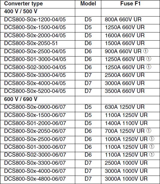
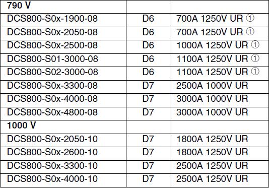
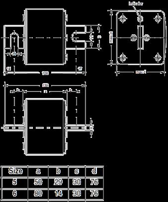
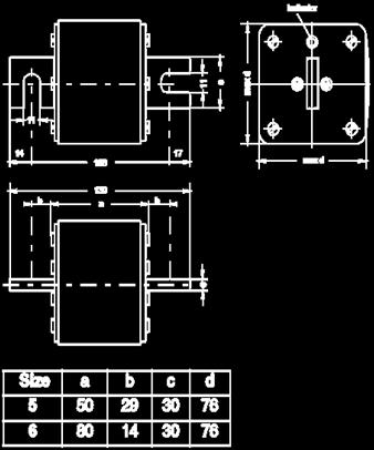
16 Semiconductor fuses D5 - D7 August 24, 2010 Slide 16
17 Summary ey points of this module are: Function of POW-4 board Internal field exciter FEX-4 25 Function of DSL board Controller board CON-4 Line reactors Dedicated transformers August 24, 2010 Slide 17
18 Additional information DCS800 Hardware Manual DCS800 Technical Catalogue (3ADW000192) (3ADW000194) August 24, 2010 Slide 18
19

20 E-Learning, DC drives DCS800 Hardware D5 D7, part 2 August 24, 2010 Slide 1 Welcome to the Hardware D5 to D7 training module part 2 for the DCS800, ABB DC Drives. If you need help navigating this module, please click the button in the top right-hand corner. To view the presenter notes as text, please click the Notes button in the bottom right corner. 1
21 Objectives After completing this module, you will be familiar with: Function of POW-4 board Internal field exciter FEX-4 25 Function of DSL board Controller board CON-4 Line reactors Dedicated transformers August 24, 2010 Slide 2 After completing this module, you will be familiar with the Function of a POW-4 board, Internal field exciter FEX-4 25 Function of DSL board Controller board CON-4 Line reactors Dedicated transformers 2
22 SDCS-POW X37 line potential! DO8 X Relay output DO8 PTC SDCS-POW X137 X99 N L Aux. supply voltage X14 24 A A 15 B B X3 X4 X5 Jumper X3 - X5 August 24, 2010 Slide 3 The SDCS-POW-4 is designed for size D5 to D7 modules. It is mounted on the electronic tray. The SDCS- POW-4 generates all necessary auxiliary voltages for the whole drive and the connected options. The power supply on the SDCS-POW-4 adjusts itself to an auxiliary supply voltage of either 230 VAC or to 115 VAC. The 230 VAC or 115 VAC auxiliary supply voltage is connected to connector X99. The input features a hardware filter and a voltage limitation. To control the main contactor a relay is provided. This relay output is controlled by digital output 8 and connected to connector X96. The function or signal definition of digital output 8 is set in the firmware by means of parameters. Connectors X37 and X137 are connected in parallel and used to connect the SDCS-POW-4 to the control board SDCS-CON-4 via flat cable. Connector X14 is used for connecting to hard parallel converters. The SDCS-POW-4 also provides different supply voltages for attached encoders. 3


23 SDCS-POW-4 August 24, 2010 Slide 4 With jumpers X3 to X5 the supply voltage can be set to either 5 V, 12 V, 15 V or 24 V. To make the different supply voltages available for the encoder connected at the SDCS-CON-4, set jumper S4 to Photo of the SDCS-POW-4 4
24 SDCS-POW-4 August 24, 2010 Slide 5 With jumpers X3 to X5 the supply voltage can be set to either 5 V, 12 V, 15 V or 24 V. To make the different supply voltages available for the encoder connected at the SDCS-CON-4, set jumper S4 to Photo of the SDCS-POW-4 5
25 FEX-425-Int Field current measurement 240 X1: 24 V supply X1:1 24 VDC X1:2 0 VDC Aux. supply voltage Output field current 35 A 5 A D X100 X110 T113 T110 T112 Field firing X1 X2 2 1 RS232 port Mains U1 V1 W X101 V110 Power part R106 R107 R108 T111 Mains voltage measurement X71 Temperature supervision D800 LED s U730 U731 S800 S801 S2 S X3 2 1 X3: DCSLink X3:1 NDB X3:2 CANL X3:3 CANH DCSLink August 24, 2010 Slide 6 The FEX-425-Int is based on a half-controlled three-phase bridge with a free-wheeling diode as the power supply and the FEX-4 as the controller board. The current measurement is automatically scaled according to the rated field current. The internal field exciter FEX-425-Int is only used for size D5 converters. If selected by its plus code, the internal field exciter FEX-425-Int is located on the left hand side of the electronic tray under the plastic cover. It can supply motor field currents up to 25 ADC. The field exciter is fully controlled and monitored by the armature converter via the DCSLink. The mains cables are connected at connector X101. The supply voltage varies between 100 VAC and 500 VAC. The field exciter is prepared to operate either with all three phases or only single phase connected. The high resistance voltage measurement of the mains voltage is located in the middle of the FEX-425-Int. The cables for the field supply are connected at connector X100. For field currents between 5 A up to 25 A, use terminal 1 marked with 35 A and terminal 3, marked with D1. For field currents between 0.3 A up to 5 A, use terminal 2, marked with 5 A and terminal 3. A direct field current measurement is done via transformer T113. The measurement of the field current is automatically scaled and selected by the firmware. The firing pulse transformers T110 to T112 for the power supply are located in the middle of the FEX-425- Int. The power block itself is soldered at the bottom of the FEX-4. It contains the half-controlled three-phase bridge with a free-wheeling diode. The PTC for the temperature supervision of the field exciter is connected at connector X71. 6
26 FEX-425-Int Field current measurement 240 X1: 24 V supply X1:1 24 VDC X1:2 0 VDC Aux. supply voltage Output field current 35 A 5 A D X100 X110 T113 T110 T112 Field firing X1 X2 2 1 RS232 port Mains U1 V1 W X101 V110 Power part R106 R107 R108 T111 Mains voltage measurement X71 Temperature supervision D800 LED s U730 U731 S800 S801 S2 S X3 2 1 X3: DCSLink X3:1 NDB X3:2 CANL X3:3 CANH DCSLink August 24, 2010 Slide 7 The auxiliary supply voltage is connected to connector X1. The input voltage of 24 VDC is connected at terminal 1 and ground is connected at terminal 2. The maximum supply current needed is less than 200 ma and the field exciter can be supplied via DSL-board. For diagnosis purposes, two LED s, the green U730 and the yellow U731, are used. All codes are listed in the DCS800 Hardware Manual. The FEX-425-Int is fully controlled and monitored by the armature converter via the DCSLink. The DCSLink cable is connected to connector X3. In the DCSLink network, each device needs a node number. The node number for the FEX-425-Int is set by means of rotary switches S800 and S801. The bus termination, ground termination and the communication speed of the DCSLink is set by means of switch S1100. The RS232-port is used for downloading the field exciter firmware. 7
27 FEX-425-Int hardware configuration Plus code +S164 3 Supply voltage maximum 600 V 3 L3 U V W F301 F302 F303 U1 V1 W1 FEX-425-Int D1(-) 5A(+) 35A(+) Plus code +S164 Maximum 500 V Only 1 phase connected Autotransformer for voltage adaptation is needed Mains L1 V1 W1 U1 PE T51 P2 4000/1 S1 P1 S2 T52 P2 4000/1 S1 P1 S2 R V14 V F14 F11 V11 V21 R11 R14 C14 C11 C21 C24 R24 R V16 V F16 F13 V13 V23 R13 R16 C16 C13 C26 C23 R26 R V12 V F15 F12 V15 V25 R15 R12 C12 C15 C22 C25 R22 R25 C1 (+) D1 (-) August 24, 2010 Slide 8 D5 converter The FEX-425-Int is built in a DCS800 converter module, size D5. The FEX-425-Int and the fuses F301 to F303 will be mounted in the D5 converter by the factory when using plus code S164. The line reactor for the field exciter is located externally and thus has to be ordered separately. The maximum supply voltage is 500 VAC. All 3 phases are connected, thus no autotransformer for voltage adaptation is needed. In case only one phase is connected, an autotransformer for voltage adaptation is needed. The maximum supply voltage with an autotransformer is 600 VAC. The line reactor for the field exciter is also located externally and thus has to be ordered separately. 8
28 DCSLink SDCS-DSL-4: One hardware for several configurations at the same time Example: excitation, 12-pulse and master - follower 12-pulse Master - follower, 12-pulse and excitation Excitation August 24, 2010 Slide 9 Bus termination The DCSLink is a multi purpose communication link for the DCS800 based on the SDCS-DSL-4 board and a simple screened twisted pair cable. One type of connection is used for communication to field exciters, for master-follower communication, drive-to-drive communication and 12-pulse communication. This slide gives an overview of the different communication types. The DCSLink is used for an armature converter controlling an external field exciter. To get a 12-pulse system, a second armature converter is added and simply connected with the first armature converter via DCSLink. Now another 12-pulse system is added and connected via DCSLink and a master follower operation is possible. Since the DCSLink is a bus system using twisted pair cables, a bus termination is mandatory at its two physical ends. This example shows the capability of the DCSLink. With one type of hardware and a simple cable connection 3 different kinds of communications can be done at once. 9


29 DCSLink wiring Node number Bus termination Bus termination August 24, 2010 Slide 10 This drawing shows a more detailed picture of the wiring. The twisted pair cable is usually shielded and contains CANbus low and CANbus high signals. The bus termination resistance of 120 Ohm is typical for a twisted pair cable and is located at both ends of the cable. The bus termination can be activated by jumper S1 on the SDCS-DSL-4 board. Every bus node requires its own unique node number. Switched off nodes can remain in the bus and do not disturb the serial communication. 10
30 SDCS-DSL-4 77 SDCS-DSL-4 X51 X52 X53 X S S Jumper S1 24 VDC output DCSLink not used Jumper S2 August 24, 2010 Slide 11 The SDCS-DSL-4 plugs into the SDCS-CON-4 and provides the DCSLink communication link for the DCS800. Connectors X52 and X53 provide the DCSLink. Both connectors provide the same function, since they are connected in parallel on the SDCS-DSL-4. Connector X51 provides 24 VDC with a maximum current of 200 ma. This power supply can be used to supply the FEX-425-Int and the external field exciters DCF and DCF To activate the bus termination set jumper S1 to 1 2. Position 2 3 is the default setting and the bus termination is disabled. To activate the ground termination use jumper S2. For ground termination via a R-C network, set jumper S2 to 2-4. For a hard ground termination, set jumper S2 to is the default setting and the ground termination is disabled. Connector X54 is currently not used and has no functionality. Photo of the SDCS-DSL-4. 11

31 SDCS-DSL-4 Jumper S1 August 24, 2010 Slide 12 The SDCS-DSL-4 plugs into the SDCS-CON-4 and provides the DCSLink communication link for the DCS800. Connectors X52 and X53 provide the DCSLink. Both connectors provide the same function, since they are connected in parallel on the SDCS-DSL-4. Connector X51 provides 24 VDC with a maximum current of 200 ma. This power supply can be used to supply the FEX-425-Int and the external field exciters DCF and DCF To activate the bus termination set jumper S1 to 1 2. Position 2 3 is the default setting and the bus termination is disabled. To activate the ground termination use jumper S2. For ground termination via a R-C network, set jumper S2 to 2-4. For a hard ground termination, set jumper S2 to is the default setting and the ground termination is disabled. Connector X54 is currently not used and has no functionality. Photo of the SDCS-DSL-4. 12


32 Fan connection D5 - D7 Configuration 4 D A Configuration 5 D6 and D A August 24, 2010 Slide 13 The converter fans are used to force cool air through the heat sink of the drive and thus the modules are cooled. The connector for all cooling fans of size D5 to D7 converters is located on the cooling fan itself. For size D5 converters with nominal currents from 900 A to 2000 A, the fan is located under the housing. The fan has a nominal incoming voltage of 230 VAC. For size D6 converters with nominal currents from 1900 A to 3000 A two types of fans are used depending on the incoming voltage. The fans either have a nominal incoming voltage of 380 VAC to 500 VAC or 525 VAC to 690 VAC. For size D7 converters with nominal currents from 2050 A to 5200 A, only one type of fan is used. The fan has a nominal incoming voltage from 400 VAC to 690 VAC. The shown connection diagram is the same for all size D6 and D7converter fans. To archive the wide incoming voltage range for the fans, the fans can be connected either in delta or in star connection. For higher incoming voltages, use the star connection. To connect the fans in delta connection, the following terminals have to be interconnected: U1 with W2, V1 with U2 and W1 with V2. To connect the fans in star connection, the following terminals have to be interconnected: U2 with V2 and W2. 13


33 Line reactors D5 1 % 4 % August 24, 2010 Slide 14 This table shows all line reactors used for size D5 modules. Standard line reactors with a uk of 1 % are available for all D5 sizes and incoming voltages from 400 VAC to 690 VAC. They are the minimum requirement in industrial environments. They feature a low inductive voltage drop and reduce deep commutation notches. Line reactors ND13 to ND16 are equipped with busbars. See design figure 3. Do not use the line reactor terminals as cable or busbar support. The line reactor ND16 used for the largest D5 unit needs small forced cooling. The air flow should be about one meter per second. Line reactors for size D5 modules with a uk of 4 % are only available on request. 14
34 Dedicated transformers for D6 and D7 August 24, 2010 Slide 15 Dedicated transformers are especially designed to supply high power converters and located before the drive. They are usually used for size D6 and D7 converters. Line reactors for these high power drives become too large and it is cheaper to use dedicated transformers. As standard, each high power drive is connected with its own dedicated transformer. It is not permitted to connect any other equipment or a second drive on the secondary side of the dedicated transformer, since the commutation notches of high power drives are usually so severe, that they disturb the proper function of the equipment or in some cases even destroy it. The relative short-circuit voltage - u k - of the dedicated transformer should be between 1 % to 10 %. For example, for a transformer with an overload of 200 % a maximum of 5 % u k is recommended. This configuration is typical for the supply of high power D6 and D7 converters. As usual, there is no rule without an exception. High power D7 converters are designed, so that they can work together with another D7 converter behind one dedicated transformer. 15
35 Dedicated transformers for D6 and D7 Standard Only one drive is connected with the dedicated transformer No additional equipment is connected with the dedicated transformer Typically for high power converters of size D6 and D7 M u k = 1 10 % u k = 1 10 % Aux. voltage Exception When using D7 converters a maximum of two D7 converters per dedicated transformer is permitted M M August 24, 2010 Slide 16 Dedicated transformers are especially designed to supply high power converters and located before the drive. They are usually used for size D6 and D7 converters. Line reactors for these high power drives become too large and it is cheaper to use dedicated transformers. As standard, each high power drive is connected with its own dedicated transformer. It is not permitted to connect any other equipment or a second drive on the secondary side of the dedicated transformer, since the commutation notches of high power drives are usually so severe, that they disturb the proper function of the equipment or in some cases even destroy it. The relative short-circuit voltage - u k - of the dedicated transformer should be between 1 % to 10 %. For example, for a transformer with an overload of 200 % a maximum of 5 % u k is recommended. This configuration is typical for the supply of high power D6 and D7 converters. As usual, there is no rule without an exception. High power D7 converters are designed, so that they can work together with another D7 converter behind one dedicated transformer. 16


36 Semiconductor fuses D5 - D7 August 24, 2010 Slide 17 This table shows all semiconductor fuses used for the D5 to D7 modules. For different module sizes and incoming voltages, different semiconductor fuses are needed. Depending on the converter type, different kinds of semiconductor fuses are used. 17
37 Summary ey points of this module are: Function of POW-4 board Internal field exciter FEX-4 25 Function of DSL board Controller board CON-4 Line reactors Dedicated transformers August 24, 2010 Slide 18 The key points of this module are: Function of a POW-4 board, Internal field exciter FEX-4 25 Function of DSL board Controller board CON-4 Line reactors Dedicated transformers 18
38 Additional information DCS800 Hardware Manual DCS800 Technical Catalogue (3ADW000192) (3ADW000194) August 24, 2010 Slide 19 19

39 20
Vector Drive - Troubleshooting Guide
 Haas Technical Documentation Vector Drive - Troubleshooting Guide Scan code to get the latest version of this document Translation Available The Haas Vector drive is the source of power for the spindle
MDK. Accelnet Module DevKit. Provides Mounting & Connections for Accelnet CANopen Servoamplifiers FEATURES
 Provides Mounting & Connections for Accelnet CANopen Servoamplifiers FEATURES Works with all Accelnet Models Develop & Debug Accelnet projects then transfer design to oem pc board. Dev Kit Model * Vdc
ACOPOSinverter P74. User's Manual. Version: 2.20 (August 2016) Model no.: Original instruction
 Model no.: Original instruction") ACOPOSinverter P74 User's Manual Version: 2.20 (August 2016) Model no.: MAACPIP74-ENG Original instruction All information contained in this manual is current as of its creation/publication. We reserve
ACOPOSinverter P74 User's Manual Version: 2.20 (August 2016) Model no.: MAACPIP74-ENG Original instruction All information contained in this manual is current as of its creation/publication. We reserve
Expansion Unit Catalog Nos , - 152, - 153, - 154, - 156, -E157
 PRODUCT DA TA SLC 150 110 Expansion Unit Catalog Nos. 1745-151, - 152, - 153, - 154, - 156, -E157 7 : The EXpdnSiQn Unit The SLC 150 expansion unit can be used with either the SLC 150 processor unit or
PSU. User s manual. Rev. 0
 PSU User s manual Rev. 0 2010 1 This user manual is for the standard version of the converter. All information in this user manual, including methods, techniques and concepts described herein, are proprietary
Service Manual Saprom S
 Service Manual Saprom S 909.0620.1-00 Contents Subject Page Machine 3 Machine Elements 3 Safety precautions 4 Common Logic Functions 5 Schematic S-Series 6 Troubleshooting guide 7 Pc-board DP-MAPRO 8 Pc-board
PFC Mini TM Power Factor Corrected AC-DC Switchers
 21 PFC Mini TM Power Factor Corrected AC-DC Switchers Overview Technical Description The PFC Mini is an extremely low profile switching power supply that combines the advantages of power factor correction,
Instruction Manual for BE-SP3 Circuit. 10/21/07
 Page 1 of 54 Instruction Manual for BE-SP3 Circuit. 10/21/07 Page 1 Index: Page 2 BE-SP3 Circuit Specifications. Page 3-4 Intro to the BE-SP3. Page 5 Basics of serial to parallel. Page 6-7 ASCII Code.
ac wave 2 supply ( analog device )
") ac wave 2 supply ( analog device ) «SPECIFIC PRODUCT SECTION» Instruction and user s manual Release 2.1 00/05 REEL S.r.l. Electronic Power Drives Via Riviera Berica, 42 36024 Ponte di Nanto - Vicenza -
ac wave 2 supply ( analog device ) «SPECIFIC PRODUCT SECTION» Instruction and user s manual Release 2.1 00/05 REEL S.r.l. Electronic Power Drives Via Riviera Berica, 42 36024 Ponte di Nanto - Vicenza -
Quantum III. Compact DC Drive Package. Slitter DC Drive Package. Quantum III
 Compact DC Drive Package The delivers a DC drive package that integrates the intelligence of the Mentor II with a space saving design that incorporates many accessories typically required in the North
24/48/120 VAC Interface Card Instruction Manual
 24/48/120 VAC Interface Card Instruction Manual Distributed by Ergonomic Partners Sales@ErgonomicPartners.com www.ergonomicpartners.com Tel: (314) 884-8884 April 2012 Part Number: -R2 Copyright 2012 Magnetek
Quick Start Guide. SEB-710 I/O Expansion board. Introduction
 SEB-710 I/O Expansion board Revision 1.0 - (March, 2011) Saflec Systems (Pty) Ltd Quick Start Guide Introduction The SEB-710 is an I/O expansion device for additional inputs and outputs. It has eight relay
TECHNICAL PRODUCT DATASHEET
 FORM-ENG-0018 REV A 06-02-03 ISO 9001 CERTIFIED Phone: (352) 629-5020 or 800-533-3569 Fax: (352)-629-2902 SUITABLE FOR EXTERNAL DISTRIBUTION TECHNICAL PRODUCT DATASHEET ES-Key Climate Control Module P/N
1. Introduction ALSPA MV DELTA
 1. Introduction ALSPA MV DELTA 1.2.4 MV3000e User Input/Output (I/O) Termination Panel The User Termination Panel, shown at Figure 1-5, provides the input and output termination facilities for signals
Description. Monitoring functions Evaluation of brush length monitoring, digital, non-floating A00
 Monitoring functions Evaluation of brush length monitoring, digital, non-floating Evaluation of brush length monitoring, digital, floating A00 A06 Non-floating brush length monitoring with use of KM01
Stellar Instruments. SC1 Controller & Display System. General User s Manual. Copyright 2013 Stellar Instruments 1
 Stellar Instruments SC1 Controller & Display System General User s Manual Copyright 2013 Stellar Instruments 1 Contents Section 1 General... 3 Section 2 Base Unit A (Multi-Event Programmable Timer)...
Standard Options. Model 4100 Position Indicating Meter. Three Phase Motor Control. Positran Transmitter
 Standard Options Model 4100 Position Indicating Meter A percent-of-full-travel meter is supplied with a trim potentiometer resistor, terminal block and connectors. A potentiometer is required in the actuator
The 2U package makes the unit suitable for using in workstations, storage systems, racks for industrial and many other applications.
 The TXP3500/4000 series of fan cooled power supplies convert the universal 3 phase AC line to an adjustable, wide range output at 3.5/4 kw and a 12 V standby output. Thanks to active current share system
MODEL DRIVER Ic Ip VDC
 Provides Mounting & Connections for Stepnet Module CANopen Stepping Driver FEATURES Develop & Debug Stepnet projects then transfer design to OEM pc board. MODEL DRIVER Ic Ip VDC -075-01 STM-075-07 5 7
Diagnostics (Logical) Diagnostics (Physical)
 Diagnostics (Physical)") Enclosure Mounted Input/Output Stations In-Cabinet I/O IP 20 Protection Ideal for Retrofits Automatic Baud Rate Sensing FDN20-4S-4XSG FDN20-4S-4XSG-E* FDN20-4S-4XSG-DIN* * Not UL Electrical Operating Current:
Enclosure Mounted Input/Output Stations In-Cabinet I/O IP 20 Protection Ideal for Retrofits Automatic Baud Rate Sensing FDN20-4S-4XSG FDN20-4S-4XSG-E* FDN20-4S-4XSG-DIN* * Not UL Electrical Operating Current:
DELOMATIC - MULTI-FUNCTION SYSTEM PART 2 INSTALLATION INSTRUCTION
 CONTENTS: 25.0...2 25.1 SYSTEM INSTALLATION...2 25.1.1 Before installing the DELOMATIC system...2 25.1.2 Installing the DGU...3 25.1.3 Installing the CP...4 25.1.4 Connecting the power supply...6 25.1.5
TXP3500/4000 Series AC-DC Industrial PSU
 TXP3500/4000 Series ACDC Industrial PSU The TXP3500/4000 series of Fan cooled power supplies convert a universal 3 phase AC I/p to an adjustable, wide range, simple o/p @ 3.5kW. Parallel operation is possible
Quick Start Installation Guide
 apc/l Quick Start Installation Guide Version A2 Document Part Number UM-201 May 2010 OVERVIEW The apc/l is an intelligent access control and alarm monitoring control panel which serves as a basic building
Vector Drive - Troubleshooting Guide
 Haas Technical Documentation Vector Drive - Troubleshooting Guide Scan code to get the latest version of this document Translation Available The Haas Vector drive is the source of power for the spindle
Vector Drive - Troubleshooting Guide
 Haas Technical Documentation Vector Drive - Troubleshooting Guide Scan code to get the latest version of this document Translation Available The Haas Vector drive is the source of power for the spindle
Upgrade Kits DCV700/DCS500/DCS600 DCS800
 Nols Muller DC drives Upgrade Kits DCV700/DCS500/DCS600 DCS800 May 13, 2013 Slide 1 Upgrade solutions for DCS500 / DCS800 drives Upgrade of DCS500 / DCS500B / DCS600 to DCS800 Available for modules DCS500
SED2 VFD NEMA Type 3R Bypass/Air Conditioner
 SED2 VFD NEMA Type 3R Bypass/Air Conditioner Description The NEMA Type 3R Bypass with Air Conditioner allows SED2 to be employed in a harsh environment. The SED2 is designed specifically for HVAC applications
Universal Motor Controller UMC22-FBP. Excellent motor protection and control ATEX ABB
 Universal Motor Controller UMC-FBP Excellent motor protection and control ATEX ABB FieldBusPlug: the concept ABB s communicative product family comprises a wide range of switching, controlling and automation
Instruction Manual for 1-Phase 1Q-Power Controller Temvar GE_3
 Instruction Manual for 1-Phase 1Q-Power Controller TABLE OF CONTENTS 1 SAFETY AND APPLICATION NOTES FOR DRIVE CONVERTERS... 2 2 DEVICE DESCRIPTION... 3 2.1 General... 3 2.2 Device Construction... 3 2.3
PSU User s manual Rev. 0 January
 PSU User s manual Rev. 0 January 2011 1 This user manual is for the standard version of the converter. All information in this user manual, including methods, techniques and concepts described herein,
BB-303 Manual Baseboard for TMCM-303
 BB-303 Manual Baseboard for TMCM-303 Trinamic Motion Control GmbH & Co. KG Sternstraße 67 D 20357 Hamburg, Germany http://www.trinamic.com BB-303 Manual (V1.04 / Jul 9th, 2007) 2 Contents 1 Features...
Data sheet MK 20 GR. Customized solution or off-the-shelf: The choice is yours!
 Data sheet MK 20 GR Customized solution or off-the-shelf: The choice is yours! MK20-GR data sheet Looking for a quick and reliable solution? Then rely on our standard products: Our universal controls provide
VersaMax IP I/O Module
 Module accepts four digital input signals and provides four digital outputs. It connects to a local bus that is interfaced to a Profibus-DP / PROFINET network by a Profibus Interface Unit (IC677PBI001)
CDN503 HIGH DENSITY I/O ADAPTER USER GUIDE
 CDN503 HIGH DENSITY I/O ADAPTER USER GUIDE 13050301 (c) Copyright DIP Inc., 1996 DIP Inc. P.O. Box 9550 MORENO VALLEY, CA 92303 714-924-1730 CONTENTS DN503 PRODUCT OVERVIEW 1 DN503 INSTALLATION 1 POWER
SLC Expansion Units Catalog Nos EI01, -El02,-El03, -El04, - IUS,-El06, -E107
 PRODUCT DA TA I YY J SLC 700 110 Expansion Units Catalog Nos. 1745-EI01, -El02,-El03, -El04, - IUS,-El06, -E107 e nit SLC 100 expansion units can be used with either the SLC 100 processor unit or SLC 150
UNT1100 Series. Binary Output Jumpers AO2 AO1 AO3 AO4 AOCM AOCM AOCM AOCM AO1. AI Switches Job Information N2 Address. Ref N2+ N2- ADDR 0 = ALL OPEN
 1 2 8 4 AI6 R R Installation Bulletin UNT1100 Issue Date 0309 UNT1100 Series Introduction The Unitary (UNT) controller (UNT1100 Series) is a digital controller with applications for air handling units,
RTK3 Logic Controller User Manual Revised
 RTK3 Logic Controller User Manual Revised 6-24-08 1 of 16 svn://software/hardware/rtk3/docs/rtk3_man.doc MRR 6/24/08 9:03 AM Overview The RTK3 is intended to simplify and expedite control wiring. Centroid
IMS Control & EPR, We keep your motors running ABB s new control & protection devices up to 18.5 kw / 20 hp
 IMS Control & EPR, 2010 01 29 We keep your motors running ABB s new control & protection devices up to 18.5 kw / 20 hp October 27, 2010 1SBC101089D0201 ABB s new control and protection devices Up to 18.5
Allen-Bradley PLCs. 100 Programmable Controller Processor Unit -Catalog Nos LPI01, -LP102, -LP103, -LP104 SLC TM. The Unit
 PRODUCT DATA SLC TM 100 Programmable Controller Processor Unit -Catalog Nos. 1745-LPI01, -LP102, -LP103, -LP104 The SLC 100 programmab/e Contro"er The SLC 100 Programmable Controller is easy to program,
PumpDrive. Self -cooling, motor-independent frequency inverter. Brief Instructions
 Brief Instructions PumpDrive 4070.801/2--11 Self -cooling, motor-independent frequency inverter Mounting variants: Motor mounting (MM) Wall mounting (WM) Cabinet mounting (CM) Brief Instructions 1 About
SECTION SOLID-STATE REDUCED VOLTAGE STARTERS
 SECTION 26 29 13.16 PART 1 - GENERAL 1.1 THE REQUIREMENT A. General: The CONTRACTOR shall provide solid-state reduced voltage motor starters, complete and operable, in accordance with the Contract Documents.
SmartFan Cirrus-9. Speed Control and Alarm for 4-Wire Fans CONTROL RESOURCES INCORPORATED. The driving force of motor control & electronics cooling.
 SmartFan Cirrus-9 Speed Control and larm for 4-Wire Fans The driving force of motor control & electronics cooling. P/N 4WR9C00-F DC Controls SmartFan Cirrus-9 is a digital fan speed control and alarm that
UEP10M005 Power Supply User s Manual
 W-Ie Ne-R UEP10M005 Power Supply User s Manual UEP10M005-A0 General Remarks The only purpose of this manual is a description of the product. It must not be interpreted a declaration of conformity for this
MAINTENANCE MANUAL. EDACS REDUNDANT POWER SUPPLY SYSTEM 350A1441P1 and P2 POWER MODULE CHASSIS 350A1441P3, P4, AND P5 POWER MODULES TABLE OF CONTENTS
 MAINTENANCE MANUAL EDACS REDUNDANT POWER SUPPLY SYSTEM 350A1441P1 and P2 POWER MODULE CHASSIS 350A1441P3, P4, AND P5 POWER MODULES TABLE OF CONTENTS SPECIFICATIONS*... 2 INTRODUCTION... 3 DESCRIPTION...
USER S MANUAL Power Supply for Backplane Vdc
 USER S MANUAL Power Supply for Backplane 20-30 Vdc D F 5 6 M E smar www.smar.com Specifications and information are subject to change without notice. Up-to-date address information is available on our
VertX. V100, V200 and V300. Installation Guide Barranca Parkway Irvine, CA USA. November Rev A.1
 15370 Barranca Parkway Irvine, CA 92618 USA VertX V100, V200 and V300 Installation Guide November 2011 6080-930 Rev A.1. Contents Introduction... 3 Parts List... 3 Product Specifications... 3 Cable Specifications...
M1000 INTELLIGENT ZONE CONTROL SYSTEM
 HARDWARE GUIDE DIMENSIONS & SPECIFICATIONS REV. 5.2 M1000 INTELLIGENT ZONE CONTROL SYSTEM ROOFTOP CONTROLLER 2 Table of Contents GENERAL INFORMATION... 3 PL-M1000 Rooftop Controller...3 Description...3
ATS22D62Q soft starter-ats22-control 220V-power 230V(15kW)/ V(30kW)
/ V(30kW)") Characteristics soft starter-ats22-control 220V-power 230V(15kW)/400...440V(30kW) Main Range of product Altistart 22 Product or component type Product destination Product specific application Component
Characteristics soft starter-ats22-control 220V-power 230V(15kW)/400...440V(30kW) Main Range of product Altistart 22 Product or component type Product destination Product specific application Component
Allen-Bradley 1397 L11 I/O Expansion Card
 Installation Instructions IN Allen-Bradley 1397 L11 Expansion Card Cat. No. 1397-L11 What This Option Provides The Expansion Card is a drive mounted board that provides these additional signals. (5) Digital
Operation Manual Profibus DP -Display HE 5120 P with digital I/O's
 Operation Manual Profibus DP -Display HE 510 P with digital I/O's "HESCH" Schröder GmbH Boschstraße 8 31535 Neustadt Telefon +49 (0) 503 / 9535-0 Telefax +49 (0) 503 / 9535-99 e-mail: info@hesch.de http://www.hesch.de
Vital. Safety controller. Approvals: Control of: Features: Entire safety system based on the dynamic safety circuit.
 Safety controller Vital Approvals: TÜV Nord Vital 1 TÜV Rheinland Vital and 3 Control of: Entire safety system based on the dynamic safety circuit. Features: Vital is based on a single channel safety concept
MXIO. Compact I/O module. Summary. Application Compact I/O module for data acquisition and HVAC control systems. Function
 MXIO Compact I/O module Summary The MXIO multiple I/O compact module is a microprocessor-controlled, communicative module with the I/O mix optimized for larger HVAC control applications. The module uses
PTC Model III. Programmable Turntable Controller. Automatic Power Router. Installation Instructions
 PTC Model III Programmable Turntable Controller A Automatic Power Router Installation Instructions New York Railway Supply 13225 Thornton Dr Westlake, TX 76262 (817) 233-5068 http://www.nyrs.com NYRS Inc2010,
MegaTrak MCU-9000 Harness Wiring
 MegaTrak MCU-9000 Harness Wiring Contents: 1. MCU9000 Connector Pin-Out Schematic 2. MCU9000 Connections when replacing an MCU3000 3. MCU9000 Connections Using 120VAC ( Hot ) Hook Switch (RS485 cable)
This Datasheet for the IC697CHS790. Rack, 9 Slots, Rear Mount.
 This Datasheet for the IC697CHS790 Rack, 9 Slots, Rear Mount. http://www.cimtecautomation.com/parts/p-14771-ic697chs790.aspx Provides the wiring diagrams and installation guidelines for this GE Series
ATS22D17Q soft starter-ats22-control 220V-power 230V(4kW)/ V(7.5kW)
/ V(7.5kW)") Characteristics soft starter-ats22-control 220V-power 230V(4kW)/400...440V(7.5kW) Main Range of product Altistart 22 Product or component type Product destination Product specific application Component
Characteristics soft starter-ats22-control 220V-power 230V(4kW)/400...440V(7.5kW) Main Range of product Altistart 22 Product or component type Product destination Product specific application Component
INTEGRATED SYSTEMS AND CONTROL, INC. User s Hardware Manual. PCMNET V 7. xx
 INTEGRATED SYSTEMS AND CONTROL, INC. User s Hardware Manual PCMNET V 7. xx INTEGRATED SYSTEMS AND CONTROLS, INC. PCMNET Users Manual Revised 2/4/2005 2003-2005 Integrated Systems and Control. Inc. PO Box
MODERNIZE YOUR DC CRANES. Convert Your DC Controls to State-of-the-Art Energy Efficient OmniPulse DDC Series 2 Drives
 TM MODERNIZE YOUR DC CRANES Convert Your DC Controls to State-of-the-Art Energy Efficient OmniPulse DDC Series 2 Drives Magnetek, the leader in digital power and motion control systems, brings you the
SIMOREG 6RA70 DC MASTER SIMOREG CM
 SIMOREG RA70 DC MASTER /2 Application /2 Design /3 Technical Data /3 Standards /4 Block diagram / Options Siemens DA 21.1 200 /1 SIMOREG RA70 DC MASTER Application An important application for the converter
Converter Box Data Sheet
 Page 1 from 6 Functions of the converter box The converter box is used to adapt physically two interfaces and to separate them galvanicly. It is configured as follows: Two interface slots can be used to
MODEL 8000MP LEVEL SENSOR
 1 MODEL 8000MP LEVEL SENSOR INSTRUCTIONS FOR INSTALLATION, OPERATION & MAINTENANCE VISIT OUR WEBSITE SIGMACONTROLS.COM 2 SERIES 8000MP LEVEL SENSOR 1. DESCRIPTION The Model 8000MP Submersible Level Sensor
ACCESSORIES Pulse Generator V4.11 Data Sheet
 03.33 Quick reference: 00 pulses per revolution of measuring drum For use with TG0 to TG0, BG4 to BG100 Uni-directional Not applicable for ex-proof areas Application: Components: Description: The Pulse
INSTALLATION DKM-409 NETWORK ANALYSER WITH HARMONIC MEASUREMENT AND SCOPEMETER. Before installation:
 DKM-409 NETWORK ANALYSER WITH HARMONIC MEASUREMENT AND SCOPEMETER The DKM-409 is a precision instrument designed for displaying various AC parameters in 3-phase distribution panels. Thanks to its isolated
Installation, Operation and Maintenance Manual
 Document 481200 VGD-100 Vari-Green Drive Installation, Operation and Maintenance Manual Please read and save these instructions for future reference. Read carefully before attempting to assemble, install,
TSXCTY2A 2 channels counter modules - 40 khz - 30 ma at 24 V DC, 280 ma at 5 V DC
 Characteristics 2 channels counter modules - 40 khz - 30 ma at 24 V DC, 280 ma at 5 V DC Main Range of product Product or component type I/O modularity Mar 05, 2018 Modicon Premium Automation platform
DESIGO RX Individual room controllers. for fan-coil systems, chilled ceilings and radiators, with LONMARK-compatible bus communications
 3 834 DESIO RX Individual room controllers for fan-coil systems, chilled ceilings and radiators, with MARK-compatible bus communications RXC20.1 RXC21.1 The RXC20.1 and RXC21.1 controllers are used for
MICROFUSION FEATURES OPTIONS CERTIFICATIONS (PENDING) THREE PHASE SCR POWER CONTROLLERS
 THREE PHASE SCR POWER CONTROLLERS") MICROFUSION THREE PHASE SCR POWER CONTROLLERS FEATURES Auto-Ranging Input Voltage 24-600 VAC, 45-65 Hz AC Output 16, 32, 50, 80 Amps (@ 50 C 6000 ft) Control Features Microprocessor-based controller /
MICROFUSION THREE PHASE SCR POWER CONTROLLERS FEATURES Auto-Ranging Input Voltage 24-600 VAC, 45-65 Hz AC Output 16, 32, 50, 80 Amps (@ 50 C 6000 ft) Control Features Microprocessor-based controller /
4.7 Digital Input/Output Module 07 DC digital inputs, 8 digital outputs, 8 configurable inputs/outputs, 24 V DC, CS31 system bus
 4.7 Digital Input/Output Module 16 digital inputs, 8 digital outputs, 8 configurable inputs/outputs, 4 V DC, CS31 system bus 1 3 Advant Controller 31 I/O Unit ERR Test 4 1 Fig. 4.7-1: Digital input/output
ADVANCED MOTION CONTROLS 3805 Calle Tecate, Camarillo, CA Tel: (805) , Fax: (805) Page 1 of 12
 , Fax: (805) Page 1 of 12") July 25, 2005 DIGIFLEX DIGITAL SERVO DRIVES MODEL: ZDR150EE12A8LDC FEATURES: Fully digital, state-of-the-art design Space Vector Modulation and vector control technology 20kHz Digital current loop with
July 25, 2005 DIGIFLEX DIGITAL SERVO DRIVES MODEL: ZDR150EE12A8LDC FEATURES: Fully digital, state-of-the-art design Space Vector Modulation and vector control technology 20kHz Digital current loop with
SD DRIVE SERIES INSTALLATION MANUAL
 SD DRIVE SERIES INSTALLATION MANUAL Description: The SD Drives are an integral part of the Centroid CNC control solution. Packaged as a complete motor drive for AC brushless as well as DC brush motor control,
Sigma XT Ancillary Board (K588)
") Sigma XT Ancillary Board (K588) Operation and Maintenance Manual Man-1095 Issue 04 October 2009 Index Section Page 1. Introduction... 3 2. Safety and mounting... 3 3. Technical specification... 4 4. Connecting
Sigma XT Ancillary Board (K588) Operation and Maintenance Manual Man-1095 Issue 04 October 2009 Index Section Page 1. Introduction... 3 2. Safety and mounting... 3 3. Technical specification... 4 4. Connecting
VersaPoint I/O Module
 Output 24VDC Positive Logic 0.5A 14 Points Module is used to output 24VDC digital signals. Module Specifications Housing dimensions (width x height x depth) Connection style Operating temperature 48.8mm
XT-9100 Technical Bulletin
 System 9100 Technical Manual 636.4 Technical Bulletins Section Technical Bulletin Issue Date 0896 XT-9100 Technical Bulletin XT-9100 Extension Module/XP-910x Expansion Modules Page 3 Introduction 3 SX
INSTRUCTION SHEET. Eaton Logic Controller ELCB Controllers
 2010-12-10 5011699201-PBB1 Eaton Logic Controller ELCB Controllers INSTRUCTION SHEET [Applicable Controllers] ELCB-PB10 ELCB-PB14 ELCB-PB20 ELCB-PB30 ELCB-PB40 IL05001005E 002-1310020-02 Thank you for
JUMO TYA 201 Single-Phase SCR Power Controller For controlling resistive/inductive loads
 Data sheet 709061 Page 1/21 JUMO TYA 201 Single-Phase SCR Power Controller For controlling resistive/inductive loads The JUMO TYA 201 represents a consistent further development of the JUMO power controller
POE084824B. PoE 54V/8x0,3A/4x7Ah PoE buffer power supply for up to 8 IP camera. v.1.1 EN* Edition: 7 from
 POE084824B v.1.1 PoE 54V/8x0,3A/4x7Ah PoE buffer power supply for up to 8 IP camera. EN* Edition: 7 from 15.11.2017 Supersedes the edition: 6 from 22.11.2016 GREEN POWER CCTV PoE PSU features: DC 54V uninterruptible
SmartFan Fusion-4. Speed Control and Alarm for DC Fans CONTROL RESOURCES INCORPORATED. The driving force of motor control & electronics cooling.
 SmartFan Fusion-4 Speed Control and Alarm for DC Fans The driving force of motor control & electronics cooling. P/N FUS300-F DC Controls SmartFan Fusion-4 is a digital fan speed control and alarm that
NT10 Series RS485 Modbus RTU Networking LCD Fan Coil Thermostat
 Features Modern Appearance Stylish rotary dial and buttons Large LCD with backlight Support Modbus RTU protocol Support standalone operation on RS485 communication failure Retention of temperature set-point
MSR 2400W. Multi purpose Power System for Telecom and Industrial Applications. Nominal Output Voltage. Voltage Setting Range
 MSR 2400W Multi purpose Power System for Telecom and Industrial Applications 2400 W modular system All voltages available 0 144VDC per module U and I adjustable from 0 to max value Hot-swap plug-in modules
This image cannot currently be displayed. Sarel Pelser. ABB Group May 27, 2014 Slide 1
 Sarel Pelser May 27, 2014 Slide 1 A BB MV Drives Centre of Excellence Welcome, Introduction What happens at A BB in Turgi? Turgi is A BB s centre of excellence for power electronics. b This image cannot
Digital DRIVE for Brushless motor MD Serial
 Digital DRIVE for Brushless motor MD Serial Installation guide Read manual before installing and respect all indications with this icon: MD-GI/EN Table of Contents 1- Introduction... 3 1-1- Warning...
ATS22D75Q soft starter-ats22-control 220V-power 230V(18.5kW)/ V(37kW)
/ V(37kW)") Product data sheet Characteristics ATS22D75Q soft starter-ats22-control 220V-power 230V(18.5kW)/400...440V(37kW) Complementary Assembly style Function available Power supply voltage limits Main Range of
Product data sheet Characteristics ATS22D75Q soft starter-ats22-control 220V-power 230V(18.5kW)/400...440V(37kW) Complementary Assembly style Function available Power supply voltage limits Main Range of
DC3IOB Revision User Guide Updated 3/29/10. Overview
 Revision 080910 User Guide Updated 3/29/10 Overview The is a three axis DC brush motor drive with an integrated PLC. A range of motor drive currents are selectable with jumper blocks. The integrated PLC
H7625A, H7635A Humidity/Temperature Sensors
 H765A, H7635A Humidity/Temperature Sensors WALL-MOUNT MODELS APPLICATION The H765A, H7635A Wall-Mount Humidity/Temperature Sensors are universal Relative Humidity transmitters that can be powered with
Saab TransponderTech. INSTALLATION GUIDE J4N Junction Box for R4 Navigation System
 Saab TransponderTech INSTALLATION GUIDE J4N Junction Box for R4 Navigation System Page i i Copyright The entire contents of this manual and its appendices, including any future updates and modifications,
ACS Product Overview
 ACS880-07 Product Overview Description Cabinet-built single drives, ACS880-07 Our cabinet-built single drives are built to order, meeting customer needs despite any technical challenges. Designed on ABB's
Diagnostics (Physical)
") DeviceNet Spanner Rugged, Fully Potted Stations IP 67 Protection Communicate Between s Connect Two DeviceNet Networks FDN-DN1 Electrical Operating Current: 125 ma from segment A, 30 ma from segment B Power
DeviceNet Spanner Rugged, Fully Potted Stations IP 67 Protection Communicate Between s Connect Two DeviceNet Networks FDN-DN1 Electrical Operating Current: 125 ma from segment A, 30 ma from segment B Power
SINGLE READER EXPANSION MODULE
 SINGLE READER EXPANSION MODULE INSTALLATION GUIDE A D C - A C X 1 TR- SINGLE READER EXPANSION MODULE The ADC-ACX1 Single Reader Expansion Module provides a solution for interfacing to a one Wiegand reader
SIMOCODE 3UF Motor Management and Control Devices
 Technical specifications General data applicable to the basic units, current measuring modules, current/voltage measuring modules, expansion modules, decoupling module and operator panel Permissible ambient
Energy 3000 Primary Switched Power Supply 3000W VE3PUID ,5/L programmable V/I
 Ordering Informations Type Output Input Dimensions Article No.* Voltage VE3PUID 300.2,5/L V = 0V - 300V* 3 x 400Vac 84HP/2U 582-00-03 I = 0A - 2,5A* * Delivery condition; Local Mode; LAB (L)-Control-Mode
MTGW. Installation Guide. CAN-RS-485 BUS Gateway
 MTGW EN Installation Guide CAN- BUS Gateway MTGW Installation Instructions 1.0 Overview Trademarks Microsoft Windows 98/2000/XP are registered trademarks of Microsoft Corporation in the United States and
Mounting Card MC1XDZPC01
 Description The MC1XDZPC01 mounting card is designed to host a DZCANTU series DigiFlex Performance TM digital servo drive. The drive plugs into the bottom side of the mounting card, providing a compact
Environdata FA ma Converter Guide
 FA12 4 20 ma Converter Guide REV 14 th July 2015 Material in this Handbook is copyright. All rights reserved by the publishers. Weather Stations Pty. Ltd., 42-44 Percy Street, Warwick, Queensland, AUSTRALIA,
Device manual AS-i PowerSwitch ZB0028 ZB0040
 Device manual AS-i PowerSwitch ZB0028 ZB0040 System AS-i Page 1 of 16 Device manual POWERSWITCH ZB0028 ZB0040 Date: 04/02/02 Contents 1. Views... 3 1.1 Top view... 3 1.2 Front view... 4 1.3 Bottom view...
TM7NCOM16A CANopen interface block - IP67-16 I/O - M12
 Characteristics CANopen interface block - IP67-16 I/O - M12 Main Range of product Product or component type Range compatibility Enclosure material Bus type [Ue] rated operational voltage Input/Output number
RXTP ROOM TEMPERATURE
 ROOM TEMPERATURE CONTROLLER WITH PI CONTROL Mounting and operating instructions Table of contents SAFETY AND PRECAUTIONS 3 PRODUCT DESCRIPTION 4 ARTICLE CODES 4 INTENDED AREA OF USE 4 TECHNICAL DATA 4
Catalog. ABB DC Drives DCS800-A Enclosed Converters 18 A to 9800 / A
 Catalog ABB DC Drives DCS800-A Enclosed Converters 18 A to 9800 / 19600 A DCS800 Drive Manuals DCS800 Drive Manuals Language Public. number E D I ES F CN RU PL PT SE DCS800 Quick Guide 3ADW000191 x x x
icex-cmtm General specs and Installation guide
 icex-cmtm General specs and Installation guide 1. General view 2. Specifications 2.1. Common specs: Ethernet 1 x 10/100Base/T, RJ45 connector with traffic and link LED Serial Interface 1 x RS232/485 USB
FEATURES DESCRIPTION MODEL 110B. Power Supply
 FEATURES Extends wiring distance of FT-10 LonWorks Networks. (2) channels using a single Model 110B. Up to 10 channels using (5) Model 110B. Low cost alternative to routers configured as repeaters. Wring
RXM39.1. PL-Link IO Block. Desigo TRA. Use with PXC3 series room automation station
 s 3 836 3836P01 Desigo TRA PL-Link IO Block Use with PXC3 series room automation station RXM39.1 The PL-Link IO Block contains the inputs and outputs controlled by a room automation station via PL-Link.