Bluetooth Low Energy CC2540/41 Mini Development Kit User s Guide
|
|
|
- Maurice Jefferson
- 6 years ago
- Views:
Transcription


1 Bluetooth Low Energy CC2540/41 Mini Development Kit User s Guide Document Number: SWRU270C Document Version: 1.2 Development Kit Part Number: CC2540DK-MINI, CC2541DK-MINI
2 TABLE OF CONTENTS 1. REFERENCES PRINTED COPY INCLUDED IN THE BOX WITH CC2540DK-MINI PRINTED COPY INCLUDED IN THE BOX WITH CC2541DK-MINI INCLUDED WITH TEXAS INSTRUMENTS BLUETOOTH LOW ENERGY SOFTWARE INSTALLER AVAILABLE FROM BLUETOOTH SPECIAL INTEREST GROUP (SIG) INTRODUCTION KIT CONTENTS OVERVIEW SYSTEM REQUIREMENTS GETTING STARTED ASSOCIATE DRIVER WITH USB DONGLE DETERMINING THE COM PORT USING BTOOL STARTING THE APPLICATION CREATING A BLE CONNECTION BETWEEN USB DONGLE AND KEYFOB Making the Keyfob Discoverable Scanning for Devices Selecting Connection Parameters Establishing a Connection KEYFOBDEMO PROFILES Reading a Characteristic Value by UUID Reading a Characteristic Value by Handle Writing a Characteristic Value Discovering a Characteristic by UUID Reading Multiple Characteristic Values Enable Notifications USING THE PROXIMITY PROFILE Activate Link Loss Service Activate Immediate Alert Read TX Power USING THE BATTERY SERVICE Read the Battery Level Activate Battery Level Notification USING THE ACCELEROMETER SERVICE Enable Accelerometer Enable Accelerometer Notifications USING THE SIMPLE KEYS GATT PROFILE Enable Simple Keys notifications USING BLE SECURITY Encrypting the Connection Using Bonding and Long-Term Keys ADDITIONAL SAMPLE APPLICATIONS PROGRAMMING / DEBUGGING THE CC2540 OR CC HARDWARE SETUP FOR KEYFOB HARDWARE SETUP FOR USB DONGLE USING SMARTRF FLASH PROGRAMMER SOFTWARE Reading or Writing a Hex File to the CC2540/ Reading or Writing the CC2540/41 Device Address SMARTRF PACKET SNIFFER GENERAL INFORMATION DOCUMENT HISTORY APPENDIX Page 2 of 38
3 1. References The following references provide additional information on the CC2540, CC2541, the Texas Instruments Bluetooth low energy (BLE) stack, and the BLE specification in general. (All path and file references in this document assume that the BLE development kit software has been installed to the default path C:\Texas Instruments\BLE-CC254x-1.3\) 1.1 Printed Copy Included in the Box with CC2540DK-MINI [1] CC2540 Mini Development Kit Quick Start Guide (SWRU272) 1.2 Printed Copy Included in the Box with CC2541DK-MINI [2] CC2541 Mini Development Kit Quick Start Guide (SWRU332) 1.3 Included with Texas Instruments Bluetooth Low Energy Software Installer (The software installer is available for download at [3] Texas Instruments Bluetooth Low Energy Software Developer s Guide (SWRU271) C:\Texas Instruments\BLE-CC254x-1.3\Documents\TI_BLE_Software_Developer's_Guide.pdf [4] TI BLE Vendor Specific HCI Reference Guide C:\Texas Instruments\BLE-CC254x-1.3\Documents\TI_BLE_Vendor_Specific_HCI_Guide.pdf [5] Texas Instruments BLE Sample Applications Guide (SWRU297) C:\Texas Instruments\BLE-CC254x-1.3\Documents\TI_BLE_Sample_Applications_Guide.pdf 1.4 Available from Bluetooth Special Interest Group (SIG) [6] Specification of the Bluetooth System, Covered Core Package version: 4.0 (30-June-2010) Page 3 of 38
 and the CC2541 Mini Development Kit (CC2541DK-MINI).")
4 2. Introduction Thank you for purchasing a Texas Instruments (TI) Bluetooth low energy (BLE) Mini Development Kit. The purpose of this document is to give an overview of the hardware and software included in the CC2540 Mini Development Kit (CC2540DK-MINI) and the CC2541 Mini Development Kit (CC2541DK-MINI). The information in this guide will get you up and running with the kit; however for more detailed information on BLE technology and the TI BLE protocol stack, please consult the Texas Instruments Bluetooth Low Energy Software Developer s Guide [3]. 2.1 Kit Contents Overview The kits contain the following hardware components including cables: CC2540 Keyfob CC2541 Keyfob CC2540 USB Dongle CC Debugger CC2540DK-MINI CC2541DK-MINI The CC2540/41 Keyfob is designed to act as a Peripheral Device (BLE Slave). Plastic casing for the keyfob is included which can be assembled by a Phillips screwdriver. The keyfob operates on a single CR2032 coin cell battery and includes a two-colored LED, a buzzer, an accelerometer and two buttons. The main difference between the CC2540 and CC2541 is a peripheral hardware change; Where CC2540 has a USB interface, the CC2541 has an I2C interface. The CC2541 is also optimized for lower power consumption. The keyfob uses SPI to interface to a 3 axis accelerometer. Note that the accelerometer sensors are different on the two keyfobs: CC2540 Keyfob v1.1 uses CMA3000d CC2541 Keyfob v1.4 uses BMA250 The CC2541 Keyfob has an LDO (TPS62730) to lower the voltage to 2.1 Volt for lower current consumption. It is possible to power the CC2541 Keyfob via the CC debugger by mounting a jumper on the header pin P1. The same can be done on the CC2540 Keyfob by mounting a 0 Ohm resistor on the R1 placeholder. The CC2540 USB Dongle can be used to emulate any Bluetooth low energy behavior but is usually acting as a Central Device (BLE Master). It connects to a Windows PC s USB Port, and is pre-loaded with necessary software to run the PC application BTool. The CC Debugger is used to flash the software onto both the USB Dongle as well as the keyfob. It can also be used for debugging software using IAR Embedded Workbench. Figure 1 Hardware Included with CC2540DK-MINI The RF Boards in this kit are FCC and IC certified and tested to comply with ETSI/R&TTE over temperature from 0 to +35 C. Caution! The kits include a non-rechargeable lithium battery. Always make sure the battery is removed from the CC2540/41 Keyfob when it is connected to an external power source (Do not apply voltage > 3.6V). Dispose the battery properly and keep out of the reach of children. If swallowed, contact a physician immediately. Caution! The kits contain ESD sensitive components. Handle with care to prevent permanent damage. Page 4 of 38

5 2.2 System Requirements To use the TI BLE software, a PC running Microsoft Windows (XP or later) is required, as well as Microsoft.NET Framework 3.5 Service Pack 1 (SP1) or greater. In order to check whether your system has the appropriate.net Framework, open up the Windows Control Panel, and select Add or Remove Programs. Amongst the list of currently installed programs, you should see Microsoft.NET Framework 3.5 SP1, as shown in Figure 2: Figure 2 System Requirements,.NET Framework 3.5 SP1 If you do not see it in the list, you can download the framework from Microsoft. From a hardware standpoint, the Windows PC must contain one free USB port. An additional free USB port is required in order to use the CC Debugger and the USB Dongle simultaneously. IAR Embedded Workbench for 8051 development environment is required in order to make changes to the keyfob software. More information on IAR can be found in the Texas Instruments Bluetooth Low Energy Software Developer s Guide [1]. For the keyfob, a small Philips screwdriver (not included in the kit) is required if you want to enclose the keyfob in the plastic case, and a CR2032 coin cell battery (included in the kit) is required for power. Page 5 of 38
, please see Chapter 5 for details on how to program the keyfob with the latest firmware.")
 has been installed. The latest BLE software can be downloaded at www.ti.com/ble-stack.")
6 3. Getting Started This section describes how to set up the software and get started with the Mini Development Kit. It is assumed that the CC2540/41 Keyfob comes pre-programmed out of the box. If not (as for older versions of the kit), please see Chapter 5 for details on how to program the keyfob with the latest firmware. It is indicated in the printed copy of the quick start guide that follows with the kit, if the keyfob and CC2540 USB Dongle has been pre-programmed. In addition, this section assumes that the latest version of the TI BLE software (v1.3 as of the release of this document) has been installed. The latest BLE software can be downloaded at Associate Driver with USB Dongle After the software installation is complete, the USB Dongle driver must be associated with the device in order to use the demo application. To associate the USB Dongle driver, first you must connect the USB Dongle to the PC s USB port, or to a USB hub that connects to the PC. The first time that the dongle is connected to the PC, a message will most probably pop-up, indicating that Windows does not recognize the device. Figure 3 PC, Found New Hardware When prompted whether to use Windows Update search for software, select No, not this time and press the Next button. On the next screen, select the option Install from a list or specific location (Advanced), and press the Next button: Figure 4 PC, Install Driver On the next screen, click the checkbox labeled Include this location in the search:, and click the Browse button. Select the following directory (assuming the default installation path was used): C:\Texas Instruments\BLE-CC254x-1.3\Accessories\Drivers Page 6 of 38


7 Figure 5 PC, Select Driver Click the Next button. This should install the driver. It will take a few seconds for the file to load. If the installation was successful, you should see the screen to the below. Click the Finish button to complete the installation. Figure 6 PC, CDC Driver Installation Complete 3.2 Determining the COM Port Once the driver is installed, you need to determine which COM port Windows has assigned to the USB Dongle. After you have completed the USB Dongle driver association in section 3.1, right-click on the Computer icon on your Start and select Properties, as shown in Figure 6. Figure 7 Win7 PC, Finding Computer Properties The System Properties window should open up. Click Device Manager as shown in Figure 8. Page 7 of 38
, the device TI CC2540 Low-Power RF to USB CDC Serial Port should appear.")

8 Figure 8 Win7 PC, Finding Device Manager A list of all hardware devices should appear. Under the section Ports (COM & LPT), the device TI CC2540 Low-Power RF to USB CDC Serial Port should appear. Next to the name should be the port number (for example, the CC2540USB Dongle uses COM8 in Figure 9). Figure 9 Win7 PC, Connected Ports List Take note of this port number, as it will be needed in order to use BTool. You may close the device manager at this point. Page 8 of 38

9 4. Using BTool BTool is a PC Application that allows a user to form a connection between two BLE devices. BTool works by communicating with the CC2540, acting as a network processor, by means of HCI vendor specific commands. The USB Dongle software (when running the HostTestRelease project) and driver create a virtual serial port over the USB interface. BTool, running on the PC, communicates with the USB Dongle through this virtual serial port. More information on the network processor configuration and the HostTestRelease project can be found in the Texas Instruments Bluetooth Low Energy Software Developer s Guide [3]. More information on the HCI interface, as well as details on the HCI vendor specific commands that are used by the CC2540/41, can be found in the TI BLE Vendor Specific HCI Reference Guide [4]. For this section, a PC running windows 7 has been used, but the procedures are essentially the same for other windows version, such as XP. 4.1 Starting the Application To start the application go into your programs by choosing Start > Programs > Texas Instruments > BLE- CC254x-1.3 > BTool. On Start-up you should be able to set the Serial Port Settings. Set the Port value to the COM port earlier noted in Section 3.2. For the other settings, use the default values as shown in Figure 10. Press OK to connect to the CC2540 USB Dongle. Figure 10 BTool, Serial Port settings When connected you should see the screen presented in Figure 11. The screen indicates that you now have a serial port connection to the CC2540 USB Dongle. The screen is divided up into a few sections: the left sidebar contains information on the CC2540 USB Dongle status. The left side of the sub-window contains a log of all messages sent from the PC to the CC2540 USB Dongle and received by the PC from the CC2540 USB Dongle. The right side of the sub-window contains a GUI for control of the CC2540 USB Dongle. Page 9 of 38
 is ready to discover other BLE devices that are advertising.")
10 Device Information Message Log Device Control Figure 11 BTool, Overview 4.2 Creating a BLE Connection between USB Dongle and Keyfob At this point the USB Dongle (central) is ready to discover other BLE devices that are advertising. The keyfob should be preloaded with the KeyFobDemo application. The full project and application source code files for KeyFobDemo is included in the BLE software development kit. At this time you will want to insert the battery (or remove and re-insert the battery to reset the device) into the keyfob (peripheral). When you insert the CR 2032 battery, the LED will be lit green for one second Making the Keyfob Discoverable When the keyfob powers up, it will not immediately go into a discoverable state. To enable advertising and make the keyfob discoverable, press the right-hand button on the keyfob once. This will turn advertisements on; making the device discoverable for 30 seconds (this value is defined in the Specification of the Bluetooth System [6]). After that time, the device will return to standby mode. To make the device discoverable again, simply press the button once again. During discoverable mode, the LED will flash red. Figure 12 Press Right Button to Turn On Advertisements Page 10 of 38
11 4.2.2 Scanning for Devices In BTool, Press the Scan button under the Discover / Connect tab, as shown in Figure 13. Figure 13 BTool, Scan for Devices The USB Dongle will begin search for other BLE devices. As devices are found, the log on the left side of the screen will display the devices discovered. After 10 seconds, the device discovery process will complete, and the USB Dongle will stop scanning. A summary of all the scanned devices will be displayed in the log window. In the example in Figure 14, one peripheral device was discovered while scanning. If you do not want to wait through the full 10 seconds of scanning, the Cancel button can be pressed alternatively, which will stop the device discovery process. The address of any scanned devices will appear in the Slave BDA section of the Link Control section in the bottom right corner of the sub-window. Page 11 of 38


12 Figure 14 BTool, Slave Address Selecting Connection Parameters Before establishing a connection, you can set up the desired connection parameters. The default values of 100ms connection interval, 0 slave latency, and 20s supervision timeout should serve as a good starting point; however for different applications you may want to experiment with these values. Once the desired values have been set, be sure to click the Set button; otherwise the settings will not be saved. Note that the connection parameters must be set before a connection is established; changing the values and clicking the Set button while a connection is active will not change the settings of an active connection. The connection must be terminated and re-established to use the new parameters. (The Bluetooth specification does support connection parameter updates while a connection is active; however this must be done using either an L2CAP connection parameter update request, or using a direct HCI command. More information can be found in the Specification of the Bluetooth System [6]) Figure 15 BTool, Connection Settings Establishing a Connection To establish a connection with the keyfob, select the address of the device to connect with, and click the Establish button as shown in Figure 16. Page 12 of 38


13 Figure 16 BTool, Establish Connection If the keyfob is still in discoverable mode, a connection should be established (if more than 30 seconds have passed since the device was previously made discoverable, press the right button on the keyfob once again). Once a connection is established, the message window will return a GAP_EstablishLink event message with a Status value of 0x00 (Success) as shown in Figure 17. Figure 17 BTool Log, Link Established In BTool, you can see your connected peripheral device in the Device Information field, as shown in Figure 18. Figure 18 BTool, Device Information Page 13 of 38
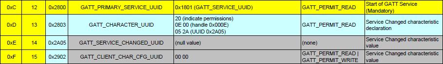
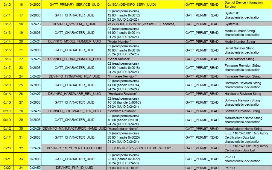
14 4.3 KeyFobDemo Profiles The KeyFobDemo software contains several GATT service profiles (More information on the KeyFobDemo can be found in the Texas Instruments BLE Sample Applications Guide [5]). GATT services contain data values known as characteristic values. All application data that is being sent or received in Bluetooth low energy must be contained within characteristic value. This section details a step-by-step process that demonstrates several processes for reading, writing, discovering, and notifying GATT characteristic values using BTool. Profiles/Services included in the KeyFobDemo are: Proximity Profile o Link Loss Service o Immediate Alert Service o TX Power Level Service Battery Service Accelerometer Service Simple Keys Service In a Bluetooth low energy system, upon connection, the Central Device (Client) performs a service discovery on the Peripheral device (server) to build up an attribute table. This attribute table will provide handles (internal addresses of the characteristics) which can be used by the Client to access the data located in the Server. The service discovery is typically an automated process that can be started with a single command. In BTool however, the automated service discovery is not implemented (although it s still possible to perform it manually). To simplify the evaluation of the KeyFobDemo, the attribute table will be known so it is possible to use handles directly to read out data. You will find the KeyFobDemo complete attribute table in the Appendix section, and can be used as a reference. Services are shown in yellow, characteristics are shown in blue, and characteristic values / descriptors are shown in grey. When working with the KeyFobDemo application, it might be useful to print out the table as a reference Reading a Characteristic Value by UUID A characteristic value is essentially where the data is stored, which could be for example temperature data or battery level. It s the stored data in a server, that a client wants to access. A characteristic is a discrete value that has the following three properties associated with it: 1. A handle (address) 2. A type (UUID) 3. A set of permissions The simplest way to read its value is to use the Read Characteristic by UUID sub-procedure. To do this, you will first need to click the Read / Write tab in BTool. Select the option Read Using Characteristic UUID under the Sub-Procedure option in the Characteristic Read section at the top of the screen. Enter the UUID (note that the LSB is entered first, and the MSB is entered last) in the Characteristic UUID box, and click the Read button. An attribute protocol Read by Type Request packet gets sent over the air from the dongle to the keyfob, and an attribute protocol Read by Type Response packet gets sent back from the keyfob to the dongle. The characteristic value is displayed in the Value box, and Success is displayed in the Status box. In addition, the message window will display information on the Read by Type Response packet that was received by the dongle. The message includes not only the characteristic s data value, but also the handle of the characteristic value Reading a Characteristic Value by Handle It is also possible to read the characteristic value if the handle is known. This is done by selecting the option Read Characteristic Value / Descriptor under the Sub-Procedure option in the Characteristic Read section. The handle is entered to the Characteristic Value Handle box and clicking the Read button which execute the read. Page 14 of 38
15 An attribute protocol Read Request packet gets sent over the air from the dongle to the keyfob, and an attribute protocol Read Response packet gets sent back from the keyfob to the dongle. The new value is displayed in the Value box, and Success is displayed in the Status box. This value should match the value that was written in the previous step Writing a Characteristic Value If a characteristic has write permission, it is possible for a client to write a value to the server. This is done in the Characteristic Write section by entering the handle into the Characteristic Value Handle box and value in the Value section (the format can be set to either Decimal or Hex ). The write operation is performed when the Write Value button is clicked. An attribute protocol Write Request packet gets sent over the air from the dongle to the keyfob, and an attribute protocol Write Response packet gets sent back from the keyfob to the dongle. The status box will display Success, indicating that the write was successful Discovering a Characteristic by UUID By discovering a characteristic by UUID, not only the handle of the UUID will be obtained, but also the properties of the characteristic (handle and permissions). The operation is performed by selecting the option Discover Characteristic by UUID under the Sub-Procedure option in the Characteristic Read section at the top of the screen. The discovery is performed when the UUID is entered in the Characteristic UUID box, and the Read button is clicked. A series of attribute protocol Read by Type Request packets get sent over the air from the dongle to the keyfob, and for each request an attribute protocol Read by Type Response packet gets sent back from the keyfob to the dongle. Essentially, the dongle is reading every attribute on the keyfob with a UUID of 0x2803 (this is the UUID for a characteristic declaration as defined in [6]), and checking the Characteristic Value UUID portion of each declaration to see if it matches the UUID type you ve entered. The procedure is complete once every characteristic declaration has been read. As per the Bluetooth specification, the first byte presents the properties of the characteristic. The second and third bytes present the handle of the characteristic value. The fourth and fifth bytes present the UUID of the characteristic Reading Multiple Characteristic Values It is also possible to read multiple characteristic values with one request, as long as the handle of each value is known. To read several values from different characteristics, select the option Read Multiple Characteristic Values under the Sub-Procedure option in the Characteristic Read section at the top of the screen. Enter the handles with semicolon separation (for example 0x0022;0x0025 ) in the Characteristic Value Handle box, and click the Read button. An attribute protocol Read Multiple Request packet gets sent over the air from the dongle to the keyfob, and an attribute protocol Read Multiple Response packet gets sent back from the keyfob to the dongle. The values of the two characteristics are displayed in the Value box, and Success is displayed in the Status box. One important note about reading multiple characteristic values in a single request is that the response will not parse the separate values. This means that the size of each value being read must be fixed, and must be known by the client. In the example here, this is not an issue since there are only two bytes in the response; however care must be taken when using this command Enable Notifications In BLE, it is possible for a GATT server device to push characteristic value data out to a client device, without being prompted with a read request. This process is called a characteristic value notification. Notifications are useful in that they allow a device in a BLE connection to send out as much or as little data as required at any point in time. In addition, since no request from the client is required, the overhead is reduced and the data is transmitted more efficiently. In order to enable notifications, the client device must write a value of 0x0001 to the client characteristic configuration descriptor for the particular characteristic. The handle for the client characteristic configuration descriptor immediately follows the characteristic value s handle. Therefore, a value of 0x0001 must be written to the handle + 1. Page 15 of 38
16 4.4 Using the Proximity Profile The Proximity profile is defined for a usage where an alert may be triggered on certain connection events, for example when the connection is, or about to be, dropped. Figure 19 Proximity Profile, Attribute Table The Proximity profile includes three services: Link Loss (Mandatory Link Loss Service (LLS) Specification v1.0) Immidiate Alert (Optional Immediate Alert Service (IAS) Specification v1.0) Tx Power (Optional Tx Power Service (TPS) Specification v1.0) Activate Link Loss Service The link loss service allows the proximity reporter to begin an alert in the event the connection drops. The link loss alert is set by writing a value to <PROXIMITY_ALERT_LEVEL_UUID> in the link loss service. The default alert value setting is 00, which indicates no alert. To turn on the alert, write a 1-byte value of 01 (low alert) or 02 (high alert). This is done in BTool by using the Characteristic Write operation as shown in Figure 20. The handle is obtained from the Proximity Profile attribute table in Figure 19. Note that this handle is unique for this solution and will probably not be the same on other solutions using Proximity Profile. Usually, the handle is obtained by performing a Discover characteristic UUID as described in Section Figure 20 Proximity Profile, Link Loss Activation Page 16 of 38
17 An attribute protocol Write Request packet gets sent over the air from the dongle to the keyfob, and an attribute protocol Write Response packet gets sent back from the keyfob to the dongle. The status box will display Success, indicating that the write was successful. By default, the link does not timeout until 20 seconds have gone by without receiving a packet. This Supervision Timeout value can be changed in the Connection Settings group in the Discover/Connect tab; however the timeout value must be set before the connection is established. After completing the write, move the keyfob device far enough away from the USB Dongle until the link drops. Alternatively, you can disconnect the USB Dongle from the PC, effectively dropping the connection. Once the timeout on the keyfob expires, the alarm will be triggered. If a low alert was set, the keyfob will make a low pitched beep. If a high alert was set, the keyfob will make a high pitched beep and the LED will blink. In either case, the keyfob will beep ten times and then stop. Alternatively to stop the beeping, either a new connection can be formed with the keyfob, or the left button can be pressed Activate Immediate Alert The Immediate Alert Service allows the proximity reporter to immediately begin an alert. The immediate alert is set by writing a value to <PROXIMITY_ALERT_LEVEL_UUID> in the immediate alert service. The default alert value setting is 00, which indicates no alert. To turn on the alert, write a 1-byte value of 01 (low alert) or 02 (high alert). This is done in BTool by using the Characteristic Write operation as shown in Figure 21. The handle is obtained from the Proximity Profile attribute table in Figure 19. Note that this handle is unique for this solution and will probably not be the same on other solutions using Proximity Profile. Usually, the handle is obtained by performing a Discover characteristic UUID as described in Section Figure 21 Proximity Profile, Immediate Alert If a low alert was set, the keyfob will make a low pitched beep for 10 seconds. If a high alert was set, the keyfob will make a high pitched beep for 10 seconds and the LED will blink. In either case, the keyfob will beep ten times and then stop. Alternatively to stop the beeping, the left button can be pressed Read TX Power The TX Power Service allows the proximity reporter to report its output power. The TX Power level is obtained by reading the characteristic value of <PROXIMITY_TX_PWR_LEVEL_UUID> in the TX Power Service. This can be done in BTool by two ways, Read Characteristic Value or Read Using Characteristic UUID. In Figure 22, the Read Characteristic Value is been used, because the handle is known. An attribute protocol Read by Type Request packet gets sent over the air from the dongle to the keyfob, and an attribute protocol Read by Type Response packet gets sent back from the keyfob to the dongle. The value is displayed in the Value box, and Success is displayed in the Status box. In addition, the message window will display information on the Read by Type Response packet that was received by the dongle. The message includes not only the characteristic s data value, but also the handle of the characteristic value (0x002B in this case). Page 17 of 38
 by pressing the left button.")
18 = -6dBm Figure 22 Proximity Profile, TX Power The output power can be toggled (0dBm and -6dBm) by pressing the left button. Page 18 of 38
 to read the percentage of battery remaining on the keyfob by reading the value of <BATTERY_LEVEL_UUID> in the Battery Service.")
19 4.5 Using the Battery Service The Battery Service exposes the Battery Level of the coin cell battery on the keyfob. Figure 23 Battery Service, Attribute Table Read the Battery Level They KeyFob used an ADC to read remaining battery level. The battery profile allows for a peer device (such as BTool) to read the percentage of battery remaining on the keyfob by reading the value of <BATTERY_LEVEL_UUID> in the Battery Service. This can be done in BTool by two ways, Read Characteristic Value or Read Using Characteristic UUID. In Figure 24, the Read Using Characteristic UUID is been used. Note that the value format is set to Decimal in this example, so roughly 61% battery left. Figure 24 Battery Service, Read Battery Level Activate Battery Level Notification In order to enable notifications, the client device (BTool in this case) must write a value of 0x0001 to the client characteristic configuration descriptor for the particular characteristic. The handle for the client characteristic configuration descriptor immediately follows the characteristic value s handle. Therefore, a value of 0x0001 must be written to handle 0x0030. Enter 0x0030 into the Characteristic Value Handle box in the Characteristic Write section, and enter 01:00 in the Value section (note that the LSB is entered first, and the MSB is entered last) as shown in Figure 25. Click the Write Value button. The status box will display Success, indicating that the write was successful. Page 19 of 38

20 Figure 25 Battery Service, Enable Notification Notification of the battery level-state is handled inside the battery service and if the battery level has dropped since the previous measurement, a notification is sent as seen in Figure 26. = 53 % = 52 % Figure 26 BTool Log, Battery Service Notification Page 20 of 38
21 4.6 Using the Accelerometer Service The keyfob uses SPI to interface to a 3 axis accelerometer on the keyfob. Note that accelerometer sensor can be of different vendors depending on the board revision. For example: CC2540 Keyfob v1.1 uses CMA3000d CC2541 Keyfob v1.4 uses BMA250 Note that the types (UUIDs) of the five characteristic values (0xFFA1, 0xFFA2, 0xFFA3, 0xFFA4, and 0xFFA5), as well as the primary service UUID value (0xFFA0), do not conform to any specifications in the Bluetooth SIG. They are simply used as a demonstration. Figure 27 Accelerometer Service, Attribute Table Enable Accelerometer The first characteristic of the Accelerometer service has both read and write permissions, and has a UUID of 0xFFA1. This characteristic is Accelerometer Enable and is used to start and stop the running of the accelerometer sensor. The accelerometer is enabled by writing a value of 01 to the characteristic. This is done in BTool by using the Characteristic Write operation as shown in Figure 28. The handle is obtained from the Accelerometer Service attribute table in Figure 27. Page 21 of 38
22 Figure 28 Accelerometer Service, Enable Accelerometer Enable Accelerometer Notifications Once the accelerometer is enabled, each axis can be configured to send notifications by writing to the characteristic configuration for each axis < GATT_CLIENT_CHAR_CFG_UUID>. In addition, the values can be read directly by reading <ACCEL_X_UUID>, <ACCEL_Y_UUID> and <ACCEL_Z_UUID>. This is done in BTool by using the Characteristic Write operation as shown in Figure 29. The handle is obtained from the Accelerometer Service attribute table in Figure 27. Figure 29 Accelerometer Service, Enable Notification on X-Axis Moving the keyfob will result in notifications being sent and received by BTool, as shown in Figure 30. Figure 30 BTool Log, X-Axis Notification It is possible to enable notifications for the other two characteristics to obtain acceleration information from x-, y- and z-axis. Page 22 of 38

23 4.7 Using the Simple Keys GATT Profile The simple keys profile on the keyfob allows the device to send notifications of key presses and key releases to a central device. Figure 31 Simple Keys Service, Attribute Table It is important to note that the simple keys profile included with the BLE development kit does not conform to any standard profile specification available from the Bluetooth SIG. At the time of the release of the software, no official GATT service profile specifications have been approved by the Bluetooth SIG. Therefore the profile, including the GATT characteristic definition, the UUID values, and the functional behavior, was developed by Texas Instruments for use with the CC254XDK-MINI development kit. As the Bluetooth SIG begins to approve specifications for different service profiles, Texas Instruments plans to release updates to the BLE software development kit with source code conforming to the specifications Enable Simple Keys notifications The UUID of the simple keys data characteristic value is 0xFFE1. Using the Discover Characteristic by UUID command, it can be determined that the handle of the simple keys data is 0x0047 (which also can directly be read from the attribute table in Figure 31). The simple keys data is a configurable characteristic, in that the client device can configure the server to send notifications of the characteristic value. The handle immediately following the characteristic value is the client characteristic configuration descriptor. The characteristic configuration of the simple keys data is the attribute at handle 0x0048. To turn on notifications, enter 0x0048 into the Characteristic Value Handle box in the Characteristic Write section, and enter 01:00 in the Value section. The format can be set to either Hex or Decimal. Click the Write button to send the write request over the air. When the keyfob receives the request, it will turn on notifications of the simple keys data, and send a write response to indicate success. With notifications enabled, an attribute protocol Handle Value Notification packet is sent from the keyfob to the dongle as you press or release either of the buttons on the keyfob. The notifications should show up in the log window. A value of 00 indicates that neither key is pressed. A value of 01 indicates that the left key is pressed. A value of 02 indicates that the right key is pressed. A value of 03 indicates that both keys are pressed. Figure 32 BTool Log, Key Press Notification Page 23 of 38

24 4.8 Using BLE Security BTool also includes the ability to make use of security features in BLE, including encryption, authentication, and bonding Encrypting the Connection To encrypt the link, the pairing process must be initiated. Click on the Pairing / Bonding tab in BTool. In the Initiate Pairing section at the top of the screen, check the boxes labeled Bonding Enabled and Authentication (MITM) Enabled, and click the button Send Pairing Request as shown in Figure 33. This will send the pairing request to the peripheral device. Figure 33 BTool, Sending Pairing Request The peripheral will send a pairing response in return, which will require a six-digit pass code to be entered by the user in order to complete the process. Typically, this pass code is intended to be used by a peripheral device containing a display. By displaying the passkey on the peripheral device and requiring the user to enter it in on the central device s user interface, the link is authenticated, in that it has been verified that the connection has not been hijacked using a man-in-the-middle (MITM) attack. In the case of the KeyFobDemo software, a fixed pass code is used, since the keyfob does not have a display (this value can be modified in the source code). In the box labeled Passkey in the Passkey Input section, enter the value and click the Send Passkey button as shown in Figure Page 24 of 38

25 34. Note that if you do not send the passkey within 30 seconds after receiving the pairing response message, the pairing process will fail, and you will need to re-send the pairing request. Figure 34 BTool, Sending Passkey When pairing is successfully completed, you will see a GAP_AuthenticationComplete event in the log window, with a Success status. The BLE connection is now encrypted as shown in Figure 35. Figure 35 BTool, Encrypted Connection Using Bonding and Long-Term Keys Bonding is a feature in BLE that allows a device, after initial pairing with a peer, to remember specific information about that peer device. In particular, the long-term key data that is generated during the initial pairing process can be stored locally. If the connection is then terminated and the two devices later reconnect, this data can be used to quickly re-initiate encryption without needing to go through the full pairing process and/or use a passkey. In addition, if a client device had enabled notifications of any characteristics on the server device while the two devices were bonded, the server device will remember the setting and the client will not have to re-enable them. After pairing has been completed with bonding enabled, the Long-Term Key (LTK) Data will be populated with some of the data from the GAP_AuthenticationComplete event that was generated during the encryption process. This data is required for re-initiating encryption upon reconnect. Click the Save Long-Term Key Data to File button to save this information to file. The data is saved as in a comma separated value (CSV) format as simple text, and can be store anywhere on disk. Be sure to note the location that the file is stored. Page 25 of 38

![More information on the bond manager can be found in the Texas Instruments Bluetooth Low Energy Software Developer s Guide [3].](/docs-images/75/71533916/images/26-1.jpg "With a bond now active, you can enable notifications of a characteristic value and have that setting remembered for later.")
26 Figure 36 BTool, Save Long-Term Key Within the keyfob, a similar process is going on, in that the KeyFobDemo software contains a bond manager that is storing the long-term key data that it had generated during encryption. Since the KeyFobDemo does not have a file system, it is simply storing the data in the nonvolatile memory of the CC2540/41. More information on the bond manager can be found in the Texas Instruments Bluetooth Low Energy Software Developer s Guide [3]. With a bond now active, you can enable notifications of a characteristic value and have that setting remembered for later. Note that if notifications were enabled before going through the pairing process, then the setting will not be stored. Therefore, you will need to re-write the value 01:00 to a client characteristic configuration descriptor. For example, write 01:00 to handle 0x0048 to enable notifications of key presses, as was done in section You should now be receiving notifications whenever the buttons are pressed or released. Because the devices are paired with bonding enabled, the bond manager in the KeyFobDemo software will store the client characteristic configuration descriptor data in nonvolatile memory. To verify that bonding worked, you will need to disconnect and re-connect. Click on the Discover / Connect tab and click the Terminate button at the bottom of the screen to disconnect from the keyfob. The message window will show a GAP_TerminateLink event with Success status as shown in Figure 37. In addition, the connection information in the upper-left corner of the screen will disappear. Figure 37 BTool, Terminate Link Page 26 of 38


27 At a later time, re-connect with the keyfob following the procedure in section 4.2. Once connected, you will notice that the simple keys notifications are no longer enabled. This is because the Simple Keys profile will always reset the value of the client characteristic configuration descriptor back to 00:00 if a connection is terminated or if the device resets. To re-initiate encryption and re-enable notifications of key presses, return to the Pairing / Bonding tab. In the Initiate Bond section, click the Load Long-Term Key Data From File button, and select the file in which the data was previously stored. The data fields will get automatically populated from the data in the file. Click the Initiate Bond button to re-enable encryption as shown in Figure 38. Figure 38 BTool, Re-Encrypt using Long-Term Keys A GAP_BondComplete event with Success status will be displayed in the log window. This indicates that the link has been re-encrypted as shown in Figure 39. You will also now be able to receive notifications now when the buttons on the keyfob are pressed or released, as the client characteristic configuration descriptor value of the key press characteristic has been stored. Any changes to the client characteristic configuration descriptor value (i.e. turning off notifications) will be saved to nonvolatile memory and remembered for next time that encryption is initiated using the long-term key. Figure 39 BTool, Bonding completed Page 27 of 38
28 4.9 Additional Sample Applications In addition to the KeyfobDemo application, the BLE software development kit includes project and source code files for several additional applications and profiles, including: Blood Pressure Sensor- with simulated measurements Emulated Keyboard- press the two buttons on the keyfob to simulate keyboard presses Heart Rate Sensor- with simulated measurements Health Thermometer- with simulated measurements Glucose Sensor with simulated measurements SimpleBLEPeripheral - with proprietary profile which implements all various types of permissions More information on these projects can be found in the Texas Instruments BLE Sample Applications Guide [5]. Page 28 of 38


29 5. Programming / Debugging the CC2540 or CC2541 The CC Debugger included with the CC254XDK-MINI kit allows for debugging using IAR Embedded Workbench for 8051, as well as for reading and writing hex files to the CC2540/41 flash memory using the SmartRF Flash Programmer software. SmartRF Flash Programmer also has the capability to change the IEEE address of the CC2540/41 device. The BLE software development kit includes hex files for both the USB Dongle as well as the keyfob. This section details the hardware setup when using the CC Debugger, as well as information on using SmartRF Flash Programmer. Information on using IAR Embedded Workbench for debugging can be found in the Texas Instruments Bluetooth Low Energy Software Developer s Guide [3]. 5.1 Hardware Setup for Keyfob If the keyfob is viewed with the LED on top and the coin cell battery holder at the bottom, then the set of pins closer to the top are the ones that should be used for connecting to the debugger. Pin 1 is the pin on the lower right side as shown in Figure 40. Figure 40 CC2540 Keyfob, Debug Connector Connect the CC Debugger to the keyfob as shown below. Be sure that the ribbon cable is oriented properly, with the red stripe connected to pin 1 as shown in Figure 41. Figure 41 CC2540 Keyfob Connected to CC Debugger Insert a coin cell battery in the keyfob to supply power to the target. NB! Note the orientation of the battery (+ up, - down). Next, connect the CC Debugger to the PC s USB port and then to the keyfob. Note that the CC debugger will by default not supply any power, but it will sense the voltage on the target (in this case the keyfob) for proper level shifting of the debug signals. The status indicator LED on the CC Debugger should turn on. If the LED is red, that means no CC2540/41 device was detected. If it is green, then a CC2540/41 device has been detected. If the keyfob is connected and the LED is red, try pressing the reset button on the CC Debugger. This resets the debugger and re-checks for a CC2540/41 device. If the LED still does not turn green, re-check that all cables are securely connected. Also verify that the CC Debugger has the latest firmware (see section 5.3). Page 29 of 38


30 Figure 42 CC Debugger Interface Once the CC Debugger is set up with the status indicator LED showing green, you are ready to either read or write a hex file from the board, or to start debugging a project using IAR Embedded Workbench. Power Savings Tip: Do not leave the CC Debugger connected to the keyfob for and extended period of time with the battery in the keyfob. This will cause a higher, constant current draw from the battery, and will significantly reduce the battery life. If you intend to perform a lot of debugging and expect to leave the debugger connected to the keyfob for a long time, it is possible to supply power directly from the CC Debugger. In this case, the first thing you need to do is to remove the battery. This is important in order to avoid any charging current to the battery. On the CC2540Keyfob, locate the pads for resistor R1, which are located immediately next to the debug header. Using a soldering iron, solder a small piece of wire across the two pads, shorting them together as shown in Figure 43. Figure 43 CC2540, Power Device Using CC Debugger On the CC2541 Keyfob, short-circuit the two pins on the P1 connector, next to the LED, with the small jumper included in the kit. WARNING! This kit includes a non-rechargeable lithium battery. To minimize risk of personal injury and/or property damage due to potential of explosion/rupture of battery due to charging the coin cell, always make sure battery is completely removed from the CC2541 Keyfob before trying to power it from the CC Debugger. As with any lithium battery, proper disposal should always be done and keep out of the reach of children at all times. Page 30 of 38
, as shown in Figure 44. Figure 44 CC2540 USB Dongle Connect the CC Debugger to the USB Dongle as shown below.")

31 5.2 Hardware Setup for USB Dongle The setup process for flashing the USB Dongle is very similar to the process when flashing the keyfob. First, plug the USB Dongle into a PC USB port (or a USB hub), as shown in Figure 44. Figure 44 CC2540 USB Dongle Connect the CC Debugger to the USB Dongle as shown below. Be sure that the ribbon cable is oriented properly, with the red stripe connected to pin 1 as shown in Figure 45. Figure 45 CC2540 USB Dongle Connected to CC Debugger Connect the CC Debugger to the PC USB port. The status indicator LED on the CC Debugger should turn on. If the LED is red, that means no CC2540 device was detected. If it is green, then a CC2540 device has been detected. If the USB Dongle is connected and the LED is red, try pressing the reset button on the CC Debugger. This resets the debugger and re-checks for a CC2540 device. If the LED still does not turn green, re-check that all cables are securely connected. Page 31 of 38
32 Figure 46 CC Debugger Interface Once the CC Debugger status LED is showing green, as shown in Figure 46, you are ready to use IAR to debug or to read or write a hex file from/to the USB Dongle. Page 32 of 38
33 5.3 Using SmartRF Flash Programmer Software Note: the instructions in the section apply to the latest version of SmartRF Flash Programmer (version ), which is available at the following URL: To start the application go into your programs by choosing Start > All Programs > Texas Instruments > SmartRF Flash Programmer > SmartRF Flash Programmer. The program start-up screen is shown in Figure 47. Figure 47 Flash Programmer Note. If you get prompted to update the EB Firmware (CC Debugger), follow the presented instructions to update the CC Debugger Reading or Writing a Hex File to the CC2540/41 To read or write a hex file to the CC2540/41, select the System-on-Chip tab (default). The connected CC2540/41 should be detected and show up in the list of devices. Under Flash image select the desired hex file that you would like to write to the device. If you are reading from the CC2540/41, under Flash image enter the desired path and filename for the hex file. To write to the CC2540/41, under Actions select Erase, program and verify. To read from the CC2540/41, under Actions select Read flash into hex-file. To begin the read or write, click the button Perform actions. If the action completes successfully, you should see the progress bar at the bottom of the window fill up, and either one of the following two messages, depending on whether a write or a read was performed: CC254X - IDXXXX: Erase, program and verify OK or CC254X - IDXXXX: Flash read OK. Page 33 of 38

34 5.3.2 Reading or Writing the CC2540/41 Device Address Every CC2540/41 device comes pre-programmed with a unique 48-bit IEEE address. This is referred to as the device s primary address, and cannot be changed. It is also possible to set a secondary address on a device, which will override the primary address upon power-up. Flash Programmer can be used to read the primary address, as well as to read or write the secondary address. To read the primary address of a device connected to the CC Debugger, select Primary under the Location option, and click the Read IEEE button. The primary device address should appear in the box on the right as shown in Figure 48. Figure 48 Flash Programmer, Read Primary address To read the secondary address, select Secondary under the Location option, and click the Read IEEE button. The secondary device address should appear in the box on the right. To set a new secondary address, select Secondary under the Location option, and enter the desired address in the box on the right. Click the Write IEEE button to perform the write. If the secondary device is set to FF FF FF FF FF FF, the device will use the primary address. If the secondary device is set to anything else, the secondary address will be used. Page 34 of 38

35 6. SmartRF Packet Sniffer The SmartRF Packet Sniffer is a PC software application used to display and store RF packets captured with a listening RF hardware node. Various RF protocols are supported, included Bluetooth low energy. The Packet Sniffer filters and decodes packets and displays them in a convenient way, with options for filtering and storage to a binary file format. Figure 49 SmartRF Packet Sniffer The CC2540 USB Dongle included with the CC2540/41 Mini Development Kit can be used as the listening hardware node, and can be useful when debugging Bluetooth low energy software applications. The SmartRF Packet Sniffer software can be downloaded at Page 35 of 38
36 7. General Information 7.1 Document History Revision Date Description/Changes SWRU270 (1.0) Initial release SWRU270A (1.0.1) Added information about packet sniffer and KeyFobDemo application SWRU270B (1.1) Updated with information from BLEv1.1 software release SWRU270C (1.2) Updated with information on CC2541DK-MINI, now based on KeyFobDemo from BLEv1.3. Added warnings about coin cell battery. Page 36 of 38

37 Appendix Page 37 of 38

38 Page 38 of 38 SWRU270C
Figure 26 CC Debugger Interface
 Figure 26 CC Debugger Interface Once the CC Debugger is set up with the status indicator LED showing green, you are ready to either read or write a hex file from the board, or to start debugging a project
Bluetooth Low Energy CC2540 Mini Development Kit User s Guide
 Bluetooth Low Energy CC2540 Mini Development Kit User s Guide Document Number: SWRU270 Document Version: 1.0.1 Development Kit Part Number: CC2540DK-MINI TABLE OF CONTENTS 1. REFERENCES... 3 1.1 PRINTED
Bluetooth Low Energy CC2540 Development Kit CC2541 Evaluation Module Kit User s Guide
 Bluetooth Low Energy CC540 Development Kit CC54 Evaluation Module Kit User s Guide Document Number: SWRU30A Development Kit Part Number: CC540DK, CC54EMK SWRU30 TABLE OF CONTENTS. REFERENCES... 4. PRINTED
Bluetooth Low Energy Protocol Stack
 APPLICATION NOTE Bluetooth Low Energy Protocol Stack R01AN2469EJ0113 Rev.1.13 Introduction This manual describes the installation, configuration and usage of. The tool controls the Renesas Bluetooth low
Wireless Sensor Networks BLUETOOTH LOW ENERGY. Flavia Martelli
 Wireless Sensor Networks BLUETOOTH LOW ENERGY Flavia Martelli flavia.martelli@unibo.it Outline Introduction Applications Architecture Topology Controller specifications: Physical Layer Link Layer Host
nblue TM BR-MUSB-LE4.0-S2A (CC2540)
") Page 1 of 5 Copyright 2002-2014 BlueRadios, Inc. Bluetooth 4.0 Low Energy Single Mode Class 1 SoC USB Serial Dongle nblue TM BR-MUSB-LE4.0-S2A (CC2540) AT HOME. AT WORK. ON THE ROAD. USING BLUETOOTH LOW
Page 1 of 5 Copyright 2002-2014 BlueRadios, Inc. Bluetooth 4.0 Low Energy Single Mode Class 1 SoC USB Serial Dongle nblue TM BR-MUSB-LE4.0-S2A (CC2540) AT HOME. AT WORK. ON THE ROAD. USING BLUETOOTH LOW
Use of ISP1507-AL Evaluation Boards
 Use of ISP1507-AL Evaluation Boards Application Note AN181103 Introduction Scope This document gives details on hardware and software for using and testing Insight SiP Bluetooth Low Energy module ISP1507-AL,
Bluetooth 4.0 Development Board (B-DB001 Base Board with B-001 core module)
") Bluetooth 4.0 Development Board ( Base Board with B-001 core module) H-2 Technik UG (haftungsbescgränkt) www.h-2technik.com Version Information Version Date Modified By Introduction 1.1 01.2018 Guo Release
Bluetooth 4.0 Development Board ( Base Board with B-001 core module) H-2 Technik UG (haftungsbescgränkt) www.h-2technik.com Version Information Version Date Modified By Introduction 1.1 01.2018 Guo Release
PM0257. BlueNRG-1, BlueNRG-2 BLE stack v2.x programming guidelines. Programming manual. Introduction
 Programming manual BlueNRG-1, BlueNRG-2 BLE stack v2.x programming guidelines Introduction The main purpose of this document is to provide a developer with some reference programming guidelines about how
Texas Instruments Tech Day Bluetooth Low Energy CC2540. ANT+ CC2570 and CC2571
 Texas Instruments Tech Day 2011 Bluetooth Low Energy CC2540 ANT+ CC2570 and CC2571 1 Agenda Overview Technology TI Solution Labs 2 Bluetooth Low Energy Bluetooth standard Part of Bluetooth Spec 4.0, July
nrf Connect Bluetooth low energy
 nrf Connect Bluetooth low energy User Guide v2.2 4399_003 v2.2 / 2018-06-21 Contents Revision history.................................. iii 1 nrf Connect Bluetooth low energy...................... 4 2
Network Processor GATT
 TEXAS INSTRUMENTS INCORPORATED Network Processor GATT How to setup GATT DB OFF CHIP on CC254X Greg Stewart 7/29/2012 This document describes how to setup a Network Processor implementation with the CC2540X
Bluetooth low energy technology Bluegiga Technologies
 Bluetooth low energy technology Bluegiga Technologies Topics Background What is Bluetooth low energy? Basic concepts Architecture Differentiation and comparison Markets and applications Background Background
This document gives details on hardware and software for using and testing Insight SiP Bluetooth Low Energy module ISP1302-BS.
 Application Note AN160301 Use of -BS Development Kit Introduction Scope This document gives details on hardware and software for using and testing Insight SiP Bluetooth Low Energy module -BS. Contents
Use of ISP1807-LR Evaluation Boards
 Use of ISP1807-LR Evaluation Boards Application Note AN181104 Introduction Scope This document gives details on hardware and software for using and testing Insight SiP Bluetooth Low Energy module ISP1807-LR,
Inside Bluetooth Low Energy
 Inside Bluetooth Low Energy Naresh Gupta BOSTON LONDON artechhouse.com Contents Preface Acknowledgments Foreword xix xxiii xxv Introduction 1 1.1 Introduction to Wireless Communication 1 1.2 Data Rates
Assembling The Shutterbug Remote DIY Kit
 Assembling The Shutterbug Remote DIY Kit Required Tools and Setup To assemble your Shutterbug Remote, you ll need a soldering iron, flux core solder, and tweezers. Solder braid and flux are also recommended
BT2540 Bluetooth 4.0 BLE (CC2540) Module Users Manual
 Module Users Manual") BT2540 Bluetooth 4.0 BLE (CC2540) Module Users Manual Revision 1.0 Online download: This manual: /images/manual/bluetooth/bt2540manual.pdf Software: http:///images/manual/bluetooth/cdrom-bt2540.rar 2012.08.31.
BT2540 Bluetooth 4.0 BLE (CC2540) Module Users Manual Revision 1.0 Online download: This manual: /images/manual/bluetooth/bt2540manual.pdf Software: http:///images/manual/bluetooth/cdrom-bt2540.rar 2012.08.31.
BLE121LR Bluetooth Smart Long Range Module 5/12/2014 1
 BLE121LR Bluetooth Smart Long Range Module 5/12/2014 1 Table of Contents Key Features Benefits BLE121LR Overview Bluetooth Smart Software Certifications Development Tools Use Cases 5/12/2014 2 Key Features
LM931 Bluetooth low energy Module
 Bluetooth low energy Module Revised 24/JAN/2017 2.50mm 1m 10.1 m m 22m Features Bluetooth v4.1 specification I2C and UART 14 ma (at 0 dbm) Current Consumption (Tx Mode) 9 digital and 3 analogue (10-bit
LM53X Development and Evaluation Product Family
 Development and Evaluation Family Revised Datasheet Version 13/MAR/2018 1.0 Overview The is the development and evaluation product family for the LM930 / LM931 Bluetooth low energy module. A great starting
CISS - Connected Industrial Sensor Solution
 CISS - Connected Industrial Sensor Solution BLE Communication Protocol 1 Table of contents 1 Change-log 3 2 General information & limitations 3 3 I40 Bluetooth Low Energy profile 4 3.1 Profile description
Use of ISP1880 Accelero-Magnetometer, Temperature and Barometer Sensor
 Use of Accelero-Magnetometer, Temperature and Barometer Sensor Application Note AN181105 Introduction Scope This application note describes how to set up a Sensor demonstration with Sensors Board that
CISS Communication Protocol Bluetooth LE
 CISS Communication Protocol Bluetooth LE BLE Communication Protocol - CISS 2 17 Table of contents 1 Change-log 3 2 General information & limitations 3 3 I40 Bluetooth Low Energy profile 4 3.1 Profile description
Bluegiga Bluetooth Smart Software v.1.3 5/28/2014 1
 Bluegiga Bluetooth Smart Software v.1.3 5/28/2014 1 Table of Contents Introduction to the Bluetooth Smart Software Bluetooth Smart Software v.1.3 5/28/2014 2 Introduction to Bluetooth Smart Software Bluetooth
CF3000 Dealer Diagnostic Tool Instruction Manual
 CF3000 Dealer Diagnostic Tool Instruction Manual Table of Contents: About the CF3000......3 Important Precautions......4 Components....5 Charging the CF3000......7 Licensing the CF3000.......8 Updating
LM930 Bluetooth low energy Module (with U.FL Connector) Standalone (With Embedded Bluetooth v4.1 Stack)
 Standalone (With Embedded Bluetooth v4.1 Stack)") Bluetooth low energy Module (with U.FL Connector) Revised 24/JAN/2017 m.11m 10 2.50mm m 22m Features Bluetooth v4.1 specification I2C and UART 14 ma (at 0 dbm) Current Consumption (Tx Mode) 9 digital and
Bluetooth low energy Module (with U.FL Connector) Revised 24/JAN/2017 m.11m 10 2.50mm m 22m Features Bluetooth v4.1 specification I2C and UART 14 ma (at 0 dbm) Current Consumption (Tx Mode) 9 digital and
CEL MeshConnect ZICM35x Test Tool User Guide
 User Guide 0011-00-17-02-000 CEL MeshConnect ZICM35x Test Tool User Guide CEL MeshConnect ZICM35x Test Tool User Guide Introduction CEL s MeshConnect EM357 Mini Modules combine high performance RF solutions
Wireless Open-Source Open Controlled Command and Control System WOCCS Design Project. User Manual
 MSD - 2011 Rochester Institute of Technology Wireless Open-Source Open Controlled Command and Control System WOCCS Design Project User Manual Revision 1 P11204 Systems Level User Manual WOCCS User Manual
PAN172x Design Guide
 1 of 17 PAN172x 2 of 17 TABLE OF CONTENTS 1. Scope of this Document... 3 2. Key benefits when using PAN1720... 3 3. Bluetooth Low Energy... 3 4. DESCRIPTION PAN17xx... 4 5. Block Diagram PAN172x Module...
ENVIRONMENTAL SENSING PROFILE
 ENVIRONMENTAL SENSING PROFILE Bluetooth Profile Specification Date 2014-Nov-18 Revision Group Prepared By SFWG Feedback Email sf-main@bluetooth.org Abstract: This profile enables a Collector device to
Bluetooth Low Energy Protocol Stack
 APPLICATION NOTE Bluetooth Low Energy Protocol Stack R01AN1375EJ0120 Rev.1.20 Introduction This manual describes the installation, configuration and usage of sample program, which is included in the Bluetooth
AN4869 Application note
 Application note BlueNRG-1, BlueNRG-2 BLE OTA (over-the-air) firmware upgrade Introduction This application note describes the BlueNRG-1 over-the-air (OTA) firmware upgrade procedures running on top of
The BlueNRG-1, BlueNRG-2 BLE OTA (over-the-air) firmware upgrade
 firmware upgrade") Application note The BlueNRG-1, BlueNRG-2 BLE OTA (over-the-air) firmware upgrade Introduction This application note describes the BlueNRG-1, BlueNRG-2 over-the-air (OTA) firmware upgrade procedures running
Application note The BlueNRG-1, BlueNRG-2 BLE OTA (over-the-air) firmware upgrade Introduction This application note describes the BlueNRG-1, BlueNRG-2 over-the-air (OTA) firmware upgrade procedures running
Texas Instruments CC2540/41 Bluetooth Low Energy Software Developer s Guide v1.3.2
 Texas Instruments CC2540/41 Bluetooth Low Energy Software Developer s Guide v1.3.2 Document Number: SWRU271F REFERENCES... 4 USEFUL LINKS... 4 1 OVERVIEW... 5 1.1 INTRODUCTION... 5 1.2 BLE PROTOCOL STACK
BLUEGIGA BLUETOOTH SMART SOFTWARE
 BLUEGIGA BLUETOOTH SMART SOFTWARE RELEASE NOTES Monday, 29 December 2014 Version 2.0 Copyright 2001-2014 Bluegiga Technologies Bluegiga Technologies reserves the right to alter the hardware, software,
Tap BLE API Documentation
 Tap BLE API Documentation Version 1.0.1 Table of contents Tap BLE API Documentation 1 Table of contents 1 General description 2 Device discovery 2 Scanning 2 Connecting & pairing 2 Usage of API 2 Types
Wireless M-Bus Suite for Panasonic Evaluation Boards. Quick Start Guide
 Wireless M-Bus Suite for Panasonic Evaluation Boards January 16, 2012 page 2 Document History 1.0 2011-07-20 First release dj 1.1 2011-07-25 Review dj 1.2 2011-07-27 Quick start changed dj 1.3 2011-09-13
Using SensorTag as a Low-Cost Sensor Array for AutoCAD
 Using SensorTag as a Low-Cost Sensor Array for AutoCAD Kean Walmsley Autodesk SD5013 In 2012 Texas Instruments Inc. launched the SensorTag, a $25 sensor array that communicates via Bluetooth Smart (also
MOD-RFID125 User Manual. All boards produced by Olimex are ROHS compliant. Rev.A, February 2008 Copyright(c) 2008, OLIMEX Ltd, All rights reserved
 2008, OLIMEX Ltd, All rights reserved") MOD-RFID125 User Manual All boards produced by Olimex are ROHS compliant Rev.A, February 2008 Copyright(c) 2008, OLIMEX Ltd, All rights reserved INTRODUCTION: FEATURES: MOD-RFID125 is an RFID station,
MOD-RFID125 User Manual All boards produced by Olimex are ROHS compliant Rev.A, February 2008 Copyright(c) 2008, OLIMEX Ltd, All rights reserved INTRODUCTION: FEATURES: MOD-RFID125 is an RFID station,
LMU Bluetooth Chipset Application Note
 Application Note 1 of 11 LMU Bluetooth Chipset Application Note Boris Velev Application Note 2 of 11 1 Introduction... 3 2 Description... 3 3 Setup... 4 3.1 LMU BT LE driver streams and serial port configuration
MOD-RFID125-BOX User Manual
 MOD-RFID125-BOX User Manual All boards produced by Olimex are ROHS compliant Rev.B, May 2011 Copyright(c) 2011, OLIMEX Ltd, All rights reserved Page 1 INTRODUCTION: FEATURES: MOD-RFID125-BOX is an RFID
ZIC2410 Getting Started Guide
 MeshConnect Family ZIC2410 Getting Started Guide 0005-05-08-11-001 (Rev E) Table of Contents 1 INTRODUCTION... 3 1.1 DEFINITIONS... 3 1.2 REFERENCED DOCUMENTS... 3 1.3 CEL ZIC2410 SYSTEM DESCRIPTION...
Quick Start Guide: RL78G14 Motor Control Starter Kit
 Document Contents 1.0 Introduction 1 2.0 Board Layout 1 3.0 Stand Alone Demonstration Mode 2 4.0 Installation 3 5.0 Using the GUI 4 6.0 RL78/G14 Programming 6 7.0 RL78/G14 Debugging 7 8.0 Next Steps 8
Adafruit Feather nrf52840 Express
 Adafruit Feather nrf52840 Express PRODUCT ID: 4062 The Adafruit Feather nrf52840 Express is the new Feather family member with Bluetooth Low Energy and native USB support featuring the nrf52840! It's our
BLE Bluetooth Low Energy Modules SBC2112-B. Preliminary Specification. Version 1.0
 BLE Bluetooth Low Energy Modules SBC2112-B Preliminary Specification Version 1.0 23-JUN.-2014 Content 1. Description...3 2. Features...3 3. Block Diagram...3 4. Radio Characteristics...4 5. Electrical
CSR102x Starter Development Kit
 CSR102x Starter Development Kit Bluetooth Low Energy Single Mode SoC Alan Hay, Applications Engineer Qualcomm Technologies International, Ltd. Kit overview Focus for today s workshop CSR1025 SoC Bluetooth
BT121 Bluetooth Smart Ready Module. May 2015
 BT121 Bluetooth Smart Ready Module May 2015 TOPICS Bluetooth Smart vs. Smart Ready Bluetooth Smart Ready Use Cases BT121 Key Features BT121 Benefits BT121 Overview Bluetooth Smart Ready Software Development
Example: Enable sleep mode
 Example: Enable sleep mode In this example, you will learn how to extend the battery life of an XBee ZigBee module. The example uses all three modules included in the kit to demonstrate how a ZigBee network
In this activity you will create a tool to allow you to play games such as Red Light/Green Light. To create the game, follow the steps below.
 Example: Hello World In this activity you will create a tool to allow you to play games such as Red Light/Green Light. To create the game, follow the steps below. If you get stuck, go to the Troubleshooting
+ (5~27 VDC) GND. Bluetooth V4.2 BLE RS-422/485 Serial Adapter. Model: BLE-485C. 1. Package content: BLE RS-422/485 adapter
 GND. Bluetooth V4.2 BLE RS-422/485 Serial Adapter. Model: BLE-485C. 1. Package content: BLE RS-422/485 adapter") Bluetooth V4.2 BLE RS-422/485 Serial Adapter 1. Package content: BLE RS-422/485 adapter Model: BLE-485C Package Contents: BLE 422/485 adapter x 1 Screw x2, Screw nut x 2 A4 User manual x 1 Mini USB Cable
Bluetooth V4.2 BLE RS-422/485 Serial Adapter 1. Package content: BLE RS-422/485 adapter Model: BLE-485C Package Contents: BLE 422/485 adapter x 1 Screw x2, Screw nut x 2 A4 User manual x 1 Mini USB Cable
Product Datasheet: DWM1001-DEV DWM1001 Module Development Board. Key Features and Benefits
 Product Datasheet: DWM1001-DEV DWM1001 Module Development Board Plug-and-Play Development Board for evaluating the performance of the Decawave DWM1001 module Easily assemble a fully wireless RTLS system,
Bluetooth Low Energy Portfolio
 Bluetooth Low Energy Portfolio February 2016 - Page 1 Price Smart Platform 3 Platforms based on BLE Combo Node Connectivity ISP0900 series Intelligent Node ISP1300 series ISP091201 ISP1500 series ISP130301
Quick Start Guide. Bluetooth Low Energy expansion board based on SPBTLE-RF module for STM32 Nucleo (X-NUCLEO-IDB05A1) Version 1.
 Version 1.") Quick Start Guide Bluetooth Low Energy expansion board based on SPBTLE-RF module for STM32 Nucleo (X-NUCLEO-IDB05A1) Version 1.5 (Feb 1, 2017) Quick Start Guide Contents 2 STM32 Nucleo Bluetooth Low Energy
Quick Start Guide Bluetooth Low Energy expansion board based on SPBTLE-RF module for STM32 Nucleo (X-NUCLEO-IDB05A1) Version 1.5 (Feb 1, 2017) Quick Start Guide Contents 2 STM32 Nucleo Bluetooth Low Energy
Internet of Things Bill Siever. New Applications. Needs. Wearables. Embedded Smarts. Simple to Setup. Networking w/ Long Battery Life (Low Power)
") Internet of Things Bill Siever New Applications Wearables Embedded Smarts Needs Simple to Setup Networking w/ Long Battery Life (Low Power) Solution: BLE A.K.A. Bluetooth Smart or Bluetooth Low Energy
Internet of Things Bill Siever New Applications Wearables Embedded Smarts Needs Simple to Setup Networking w/ Long Battery Life (Low Power) Solution: BLE A.K.A. Bluetooth Smart or Bluetooth Low Energy
General Warranty. For more details, please refer to the user manual, it can be downloaded at
 General Warranty OWON warrants that the product will be free from defects in materials and workmanship for a period of 1 year from the date of purchase of the product by the original purchaser from the
QSG107: SLWSTK6101A/B Quick-Start Guide
 QSG107: SLWSTK6101A/B Quick-Start Guide The Blue Gecko Bluetooth Smart Wireless Starter Kit is meant to help you evaluate Silicon Labs Blue Gecko Bluetooth Smart modules and get you started with your own
5.1 Configure each Sensor Pin Rename Set Rules Export Data Switching Nodes... 25
 Hi-Gate User Manual Hi-Gate User Manual Hi-Gate User Manual Contents 1 Introduction... 3 1.1 Hi-Gate... 3 1.1.1 What is Hi-Gate... 3 1.1.2 Specifications... 3 1.1.3 Features... 4 1.2 Hi-Node... 5 1.2.1
QSG107: SLWSTK6101A/B Quick-Start Guide
 QSG107: SLWSTK6101A/B Quick-Start Guide Note: The contents of this document are deprecated. Please see QSG139: Bluetooth Development with Simplicity Studio for current instructions. The Blue Gecko Bluetooth
User Manual Bluetooth USB Dongle
 User Manual Bluetooth USB Dongle BTDG-40S 1. What s in the box? 1 2. General guidance 1 3. How to use with Native Windows 10 PC Plug and play 1 3.1) Windows own Bluetooth driver Auto installation 1 3.2)
DS2756EVKIT+ High Accuracy Battery Fuel Gauge With Programmable Suspend Mode Evaluation Kit
 19-4847; Rev 9/09 www.maxim-ic.com FEATURES Demonstrates the capabilities of the DS2756 High Accuracy Battery Fuel Gauge, including: Programmable Suspend Mode Temperature measurement Voltage measurement
+ (5~27 VDC) GND. Bluetooth V4.2 BLE RS-232 Serial Adapter. Model: BLE-232D-E. 1. Package content: BLE RS-232 adapter
 GND. Bluetooth V4.2 BLE RS-232 Serial Adapter. Model: BLE-232D-E. 1. Package content: BLE RS-232 adapter") 1. Package content: BLE RS-232 adapter Bluetooth V4.2 BLE RS-232 Serial Adapter Model: BLE-232D-E Package Contents: BLE RS-232 adapter x 1 A4 User manual x 1 Mini USB Cable x 1 White Box: 11 x 6 x 5 (cm)
1. Package content: BLE RS-232 adapter Bluetooth V4.2 BLE RS-232 Serial Adapter Model: BLE-232D-E Package Contents: BLE RS-232 adapter x 1 A4 User manual x 1 Mini USB Cable x 1 White Box: 11 x 6 x 5 (cm)
RC-SV Configuration Guide Revision 3
 Kramer Electronics, Ltd. RC-SV Configuration Guide Revision 3 Software Version 2.1.2.32 Intended for Kramer Technical Personnel or external System Integrators. To check that you have the latest version,
LM961 Bluetooth Dual Mode Module Standalone (With Embedded Bluetooth v4.1 Stack)
") Bluetooth Dual Mode Module Revised 13/DEC/2017 18.9mm 2.55mm 12.71mm Features Bluetooth v4.1 specification (Dual Mode) Fully integrated module with no additional components required Class 1 Tx Out Power
Bluetooth Dual Mode Module Revised 13/DEC/2017 18.9mm 2.55mm 12.71mm Features Bluetooth v4.1 specification (Dual Mode) Fully integrated module with no additional components required Class 1 Tx Out Power
RN-171-EK Evaluation Board
 RN -17 1-E K-DS RN-171-EK Evaluation Board Features Ultra-low power: 4-uA sleep, 40-mA Rx, 180-mA Tx at 10 dbm Configurable transmit power: 0 to +12 dbm UART hardware interfaces and SPI slave Up to 1 Mbps
RC-SV Configuration Guide (Rev 4)
") Kramer Electronics, Ltd. RC-SV Configuration Guide (Rev 4) Software Version 2.1.2.69 Intended for Kramer Technical Personnel or external System Integrators. To check that you have the latest version, go
Kramer Electronics, Ltd. RC-SV Configuration Guide (Rev 4) Software Version 2.1.2.69 Intended for Kramer Technical Personnel or external System Integrators. To check that you have the latest version, go
Introduction to Bluetooth Low Energy
 Introduction to Bluetooth Low Energy Qualcomm Bluetooth Low Energy Terminology clarification In this document you will notice a number of references are made to Qualcomm Bluetooth Low Energy SDK. While
Product Specification
 Product Specification Features Amp ed RF, Inc. Description 15mm x 27mm The added class 1 power, +18dBm, of the BT-11, gives this module one of the best ranges in the industry. It s completely pin compatible
EV Software Rev Evaluation System User Guide. Introduction. Contents. Hardware and Software Setup. Software Installation
 Contents Evaluation System User Guide Software Rev 2.0.1 Introduction Section Page No. Introduction 1 Kit Contents 1 Hardware and Software Setup 1 Software Installation 1 Hardware Connection 1 Operation
RN-111B-EVAL IGRN111B-EVAL 3/10/2009. WiFly evaluation Kit. Features. Description. Getting Started
 WiFly evaluation Kit Features Contains all hardware and software components required to configure and setup Roving Networks WiFly 802.11 modules. Supprts Windows based computers via serial or USB interface.
QSG107: SLWSTK6101A Quick-Start Guide
 QSG107: SLWSTK6101A Quick-Start Guide SLWSTK6101A Blue Gecko Bluetooth Smart Module Wireless Starter Kit Quick-Start Guide The Blue Gecko Bluetooth Smart Wireless Starter Kit is meant to help you evaluate
RN-WIFLY-EVAL-UM. WiFly Evaluation Kit Roving Networks. All rights reserved. RN-WIFLY-EVAL-UM-1.0 Version /8/2011 USER MANUAL
 RN-WIFLY-EVAL-UM WiFly Evaluation Kit 0 Roving Networks. All rights reserved. RN-WIFLY-EVAL-UM-.0 Version.0 //0 USER MANUAL OVERVIEW This document describes the hardware and software setup for Roving Networks
BlueCore. Operation of Bluetooth v2.1 Devices. Application Note. Issue 7
 BlueCore Operation of Bluetooth v2.1 Devices Application Note Issue 7 Page 1 of 26 Document History Revision Date History 1 06 DEC 07 Original publication of this document. 2 27 MAR 08 Bonding description
Data Capture for Workforce in Motion. D-Fly User Guide. Baracoda TM February 2010
 D-Fly User Guide Baracoda TM February 2010 SUMMARY SUMMARY 2 REVISION HISTORY 3 INTRODUCTION 4 1. STYLUS 5 2. BATTERY 5 3. SWITCHING ON THE READER 5 4. QUICK START UP GUIDE 6 4.1. HOW TO READ BARCODES
LPC2148 DEV BOARD. User Manual.
 LPC2148 DEV BOARD User Manual www.coineltech.com www.coineltech.com Designed by CoiNel Technology Solutions LLP No-816, 2 nd Floor, 4 th B Cross, 9 th A Main, RPC Layout, Vijaynagar, Bangalore-560040 State:
nblue TM BR-LE4.0-S2A (CC2540)
") Page 1 of 7 Copyright 2002-2014 BlueRadios, Inc. Bluetooth 4.0 Low Energy Single Mode Class 1 SoC Module nblue TM BR-LE4.0-S2A (CC2540) AT HOME. AT WORK. ON THE ROAD. USING BLUETOOTH LOW ENERGY WIRELESS
Page 1 of 7 Copyright 2002-2014 BlueRadios, Inc. Bluetooth 4.0 Low Energy Single Mode Class 1 SoC Module nblue TM BR-LE4.0-S2A (CC2540) AT HOME. AT WORK. ON THE ROAD. USING BLUETOOTH LOW ENERGY WIRELESS
Chicony Standard Bluetooth Keyboard Users Manual. Model No.: KT-1063
 Chicony Standard Bluetooth Keyboard Users Manual Model No.: KT-1063 Issue: Jan. 03, 2011 Scope Getting Start Thank you for choosing this ultrathin keyboard with Bluetooth technology to ensure no hinder
Product Specification
 Product Specification 15mm x 27mm Description One of the most capable Bluetooth modules available, the BT-21 Bluetooth OEM Module is designed for maximum flexibility. The BT-21 module includes 14 general
BT 31 Data Sheet. Amp ed RF Technology Inc.
 BT 31 Data Sheet Amp ed RF Technology Inc. Product Specification BT31 Features Bluetooth features FCC&Bluetooth licensed radio Bluetooth v3.0 Class 1 radio Range up to 100m LOS 1.5Mbps data throughput
MicroBot Push User Guide
 MicroBot Push User Guide Troubleshooting 24 My Microbot App does not detect my MicroBot Push 24 MicroBot Push keeps disconnecting 25 MicroBot Push is not updating 25 Getting Started 2 Meet MicroBot Push
TI SimpleLink dual-band CC1350 wireless MCU
 TI SimpleLink dual-band CC1350 wireless MCU Sub-1 GHz and Bluetooth low energy in a single-chip Presenter Low-Power Connectivity Solutions 1 SimpleLink ultra-low power platform CC2640: Bluetooth low energy
ez430-chronos Wireless Watch Development Tool: Teardown & Getting Started
 ez430-chronos Wireless Watch Development Tool: Teardown & Getting Started www.ti.com/chronoswiki ez430-chronos for wireless networking applications Complete hardware, software and support community Simplify
Product Overview: DWM1001-DEV DWM1001 Module Development Board. Key Features and Benefits
 Product Overview: DWM1001-DEV DWM1001 Module Development Board Plug-and-Play Development Board for evaluating the performance of the Decawave DWM1001 module Easily assemble a fully wireless RTLS system,
M2 OLED Temperature Monitor Instructions PN 1841
 M2 OLED Temperature Monitor Instructions PN 1841 Installation Checklist Check for components included Read Warning and Cautions Read page 3 for mounting instructions Read System Overview, Mounting Considerations,
User Manual Revision: A04 June 23, QuEST Rail LLC.
 User Manual 095-110006- 0003 Revision: A04 June 23, 2015 2015 QuEST Rail LLC. QLCP User Manual Page 2 Contents About This Manual... 4 Customer Support... 4 1 Get to Know Your QLCP... 5 2 DIP Switch and
GATEKEEPER. Protect Your Privacy. User Manual v2.0. Untethered Labs, LLC GATEKEEPER USER MANUAL V2.0 1
 GATEKEEPER Protect Your Privacy User Manual v2.0 WWW.GKCHAIN.COM Untethered Labs, LLC GATEKEEPER USER MANUAL V2.0 1 Product Overview Package Contents GateKeeper Key GateKeeper USB Lock CR2032 Battery Key
Bluetooth 4.0 USB Adapter
 Bluetooth 4.0 USB Adapter Model 604002 Supports Windows XP, Vista, 7, 8.1, 10 Windows 8.1 and 10 auto-installs Bluetooth drivers Drivers on DVD for Windows XP, Vista, 7 (download from Cable Matters) Pair
User-Configurable Desktop USB and Bluetooth Pushbuttons with hundreds of uses limited only by your imagination, for example:
 User-Configurable Desktop USB and Bluetooth Pushbuttons with hundreds of uses limited only by your imagination, for example: Dedicated browser navigation to a specific website Automate often-used phrases
nrf5x OTA Testing with LitePoint Bluetooth Advanced nwp_028
 nrf5x OTA Testing with LitePoint Bluetooth Advanced nwp_028 White Paper v1.0 / 2018-01-03 Contents 1 Revision history.................................. iii Introduction. 4..................................
BT740 Development Kit Quick Start Guide v1.2
 v1.2 This applies to the following part numbers: DVK-BT740-SA DVK-BT740-SC INTRODUCTION There are two hardware variants (on board antenna and ufl connector for external) of the BT740 Enhanced Data Module
Bluetooth Light Gun. Please also see the Aimtrak Setup Guide at : Setup Guide.pdf
 Bluetooth Light Gun Please also see the Aimtrak Setup Guide at : www.ultimarc.com/aimtrak Setup Guide.pdf 1 Contents Section 1: Introduction... 3 Features... 3 Bluetooth SIG Qualification.... 3 Section
SMART Technologies. Introducing bluetooth low energy and ibeacon
 SMART Technologies Introducing bluetooth low energy and ibeacon In real life you may call me Frederick Bousson Competence Leader Mobile @ Ordina Smartphone as life s remote control Focus on Software Development
+ (5~27 VDC) GND. Bluetooth V4.1 BLE RS-232 Serial Adapter. Model: BLE-232B. 1. Package content: BLE RS-232 adapter
 GND. Bluetooth V4.1 BLE RS-232 Serial Adapter. Model: BLE-232B. 1. Package content: BLE RS-232 adapter") Bluetooth V4.1 BLE RS-232 Serial Adapter 1. Package content: BLE RS-232 adapter Model: BLE-232B Package Contents: BLE RS-232 adapter x 1 Screw x2, Screw nut x 2 A4 User manual x 1 Mini USB Cable x 1 White
Bluetooth V4.1 BLE RS-232 Serial Adapter 1. Package content: BLE RS-232 adapter Model: BLE-232B Package Contents: BLE RS-232 adapter x 1 Screw x2, Screw nut x 2 A4 User manual x 1 Mini USB Cable x 1 White
Section 2: Getting Started with a FPU Demo Project using EK-LM4F232
 Stellaris ARM Cortex TM -M4F Training Floating Point Unit Section 2: Getting Started with a FPU Demo Project using EK-LM4F232 Stellaris ARM Cortex TM -M4F Training: Floating Point Unit Section 2 Page 1
Operating Instructions for Memo-Chip BL2
 Operating Instructions for Memo-Chip BL2 Software at: http://www.lignomat.com/bl2/ Connection between BL2 and BluePeg Sensor via Adapter RH Monitoring ambient conditions Connection between BL2 and BluePeg
TABLE OF CONTENTS COPYRIGHT INTRODUCTION...3 PRODUCT OVERVIEW...3 COMPONENTS AND FEATURES...3 HARDWARE INSTALLATION
 TABLE OF CONTENTS COPYRIGHT...2 1. INTRODUCTION...3 PRODUCT OVERVIEW...3 COMPONENTS AND FEATURES...3 HARDWARE INSTALLATION...3 2. MFP SERVER INSTALLATION...5 PREPARATION...5 CONFIGURATION SOLUTION TABLE...5
MeshConnect ISP / WNA (ZIC2410USB-WNA-1) User Guide
 User Guide") MeshConnect Family MeshConnect ISP / WNA (ZIC2410USB-WNA-1) User Guide 0007-05-08-06-001 (REV B) TABLE OF CONTENTS INTRODUCTION 3 CEL MESHCONNECT ISP / WNA FEATURES 3 GETTING STARTED 4 USB SETUP 4 MESHCONNECT
MeshConnect Family MeshConnect ISP / WNA (ZIC2410USB-WNA-1) User Guide 0007-05-08-06-001 (REV B) TABLE OF CONTENTS INTRODUCTION 3 CEL MESHCONNECT ISP / WNA FEATURES 3 GETTING STARTED 4 USB SETUP 4 MESHCONNECT
BLE Command Line Interface Document
 BLE Command Line Interface Document BLE Command Line Interface Sheet 1 of 31 V1.18 Nov 11, 2016 Index: 1. Introduction... 6 Supported Platform... 7 Reference... 7 2. Commands Status Responses... 8 2.1
ArduCAM USB Camera Shield
 ArduCAM USB Camera Shield User Guide Rev 1.0, April 2017 Table of Contents 1 Introduction... 2 2 Hardware Installation... 2 2.1 Primary Camera Interface... 2 2.2 Secondary Camera Interface... 3 3 Device