MRC-NT Microprocessor Rapper Control Operating Manual
|
|
|
- Stephen Roberts
- 6 years ago
- Views:
Transcription

1 MRC-NT Microprocessor Rapper Control Operating Manual Version 1.12A
2 Table of Contents CHAPTER 1 EQUIPMENT DESCRIPTION... 4 CHAPTER 2 OPERATION... 5 CHAPTER 3 PROGRAMMABLE PARAMETERS AND FEATURES... 7 DEFINITION OF PROGRAMMABLE PARAMETERS...8 Abort Power Down [prompt]...8 Alarm Check [key]...8 Alarm Level Adjust [prompt]...8 Clear Alarms [prompt]...8 Clock Enable [prompt]...8 Code [key]...8 Cycle Clock [key]...9 Display Setup [prompt]...9 Enable [key]...9 Enter [key]...9 ESC [key]...9 Feedback Display [prompt]...9 Help [key]...10 Intensity [key]...10 Lift Calibration [prompt]...10 Master Intensity [key]...10 Numeric Keys...10 Number of Raps [prompt]...10 Program Number [prompt]...10 Re-init Controller [prompt]...11 Re-init Keypad/Disp [prompt]...11 Repeat [key]...11 Select [key]...11 Sequence (Seq) [key]...11 Sequence Lift [prompt]...12 Software Version [prompt]...12 Step [key]...12 Start/Stop [key]...12 Wait Clock Time [prompt]...12 CHAPTER 4 DIGITAL DISPLAY Device Status Screen...13 Prompt Screen...14 Parameter Screen...14 ALARMS DISPLAYS..14 Stand Alone...15 Repeat Mode...15 Sequence Mode...15 Redkoh Industries Page 2 of 56
3 Communications Error...15 Disabled Clock...15 Disabled Device...15 High Current Device...15 Med. Current Device...15 Low Current Device...15 CHAPTER 5 PROGRAMMING INSTRUCTIONS CODE ENTRY...17 SELECT...18 STEP...18 REPEAT...19 SEQ (Sequence)...19 CYCLE CLOCK...20 INTENSITY...21 MASTER INTENSITY...22 UP & DOWN ARROWS ( and )...23 ENABLE...23 HELP...24 CODE...24 ESC (escape)...25 ALARM CHECK...25 START/STOP...26 PROMPT PARAMETERS...26 PROGRAM NUMBER...26 DISPLAY SETUP...27 RE-INIT CONTROLLER...28 RE-INIT KEYPAD/DISP...28 SOFTWARE VERSION...29 ALARM LEVEL ADJUST...30 FEEDBACK DISPLAY...31 ABORT POWER DOWN...32 LIFT CALIBRATION...33 SEQUENCE LIFT...34 NUMBER OF RAPS...34 WAIT CLOCK TIME...35 CLOCK ENABLE...36 CLEAR ALARMS...37 CHAPTER 6 OPTIMIZING OPERATION CHAPTER 7 BACK-UP PROGRAM CHAPTER 8 COMPONENTS AND CONFIGURATION APPENDIX I PROGRAMMING DATA SHEETS APPENDIX II FEEDBACK DISPLAY ALARM VALUES APPENDIX III CONTROL AND COMPONENT DRAWINGS Redkoh Industries Page 3 of 56
4 CHAPTER 1 EQUIPMENT DESCRIPTION A standard device for cleaning discharge and collecting electrodes for most applications is the magnetic impulse type rapper. These impulse type rappers consist of a copper or aluminum coil wound around an electrically insulated tube. Typically, a 20 pound, 2 inch diameter, steel plunger sits inside the tube (the diameter and weight are installation specific). When a burst of power is applied to the wire coil a magnetic field is created. This magnetic field lifts the plunger and then releases it. When the weight is released it drops, striking a steel rod that transmits a high acceleration shockwave to the attached precipitator electrodes. This microprocessor rapper controller is designed specifically for electrostatic precipitator applications. As many as 512 rappers can be operated by a single microprocessor control, which has the capability of being field programmed for frequency of rapper energization as well as the lift (impact energy) of the plungers. The controller design utilizes state-of-the-art components for maximum flexibility and high reliability in industrial environments. This manual describes the various operating parameters of the microprocessor rapper control. It also describes how to field program the control to optimize internal precipitator cleanliness, reduce re-entrainment, and minimize precipitator outlet emissions. Redkoh Industries Page 4 of 56
5 CHAPTER 2 OPERATION For purposes of control, the rappers are divided into groups based on their location on the precipitator roof and the electrode type being cleaned. Each group of rappers is assigned a separate Cycle Time clock and Wait Time clock to allow field programming of rapper repetition rate. Energization of rappers 1 through 20 corresponds to the timing of the Cycle Clock. Time between energization of rapper 20 and re-energization of rapper 1 corresponds to the timing of the Wait Cycle Clock. Redkoh Industries Page 5 of 56
6 Each group is also assigned a rapper plunger lift that can be adjusted by individual rapper to optimize the cleaning energy. Rappers can also be programmed to strike multiple blows. Other programmable functions are also available as detailed under the programming instructions. A rapper program is established at the time of startup and usually does not require changing unless a major change in fuel or firing characteristics occurs in the boiler. If changes in the rapping program arte required, the following should be kept in mind: 1. Excessive rapping of collecting electrodes causes re-entrainment of collected ash, and loss of collection efficiency. 2. Excessive rapping causes fatigue failure of internal components. 3. Inadequate rapping causes high spark rates, low electrical power, and loss of collection efficiency. 4. Because particulate collection is concentrated at the inlet of the precipitator, rapping should be hardest and most frequent on the inlet field, and progressively less on downstream fields. Through the use of EPROMs, the program is maintained permanently without battery backup, while remaining changeable by the user. The control is shipped with a program in memory that is adequate for operation and which can be optimized according to field conditions. A Program Data Sheet is provided in Chapter 6 for documenting field program changes. This Data Sheet, in conjunction with roof layout drawings, shows the grouping of the rappers. Redkoh Industries Page 6 of 56
7 CHAPTER 3 PROGRAMMABLE PARAMETERS AND FEATURES The following is a list (in alphabetical order) of the operating parameters and features incorporated in the rapper control. This list is followed by definitions, and later in this manual, detailed instruction on how the parameters are programmed. Abort Power Down Alarm Check Alarm Level Adjust Clear Alarms Clock Enable Code Cycle Clock Display Setup Enable Enter ESC Help Intensity Lift Calibration Master Intensity Number of Raps Program Number Re-init Controller Re-init Keypad/Disp Repeat Select Sequence Lift Software Version Step Start/Stop Wait Clock Time Redkoh Industries Page 7 of 56
8 DEFINITION OF PROGRAMMABLE PARAMETERS The following definitions explain the programmable parameters available in the microprocessor rapper control either directly through a key on the keypad or through a prompt screen called up using the up and down arrow keys. Programming instructions are presented later in this manual. All programmable parameter values are entered into control memory through a 16-key, sealed membrane, dual-function keypad located on the control panel door. To prevent tampering with the control, a four-digit security access code is required to gain access to the programming mode. Abort Power Down [prompt] This is used to immediately stop a power down clock from continuing to activate. This prompt only appears if the control is equipped with the power down rapping feature. Alarm Check [key] Used to display the RAPPER or CLOCK NUMBER that caused an alarm. If more than one rapper or clock has alarmed, repeatedly pushing the ALARM CHECK key will display each alarmed rapper or clock in numerical order. Alarm Level Adjust [prompt] There are three levels of control alarm. The low level senses low current levels related to open circuits, the medium level senses high current levels associated with leakage to ground or more than one rapper firing at a time, and the high level is associated with a short to ground. The Alarm Level Adjust allows the levels that produce their respective alarms to be trimmed to eliminate false alarms. Clear Alarms [prompt] Allows all alarms that are present on the control to be cleared at one time. It also allows the control to try and reenergize rappers that had previously been taken out of service due to the alarm(s). If the alarm condition is still present the rapper will again be removed from service and an appropriate alarm displayed. Clock Enable [prompt] Allows individual clocks to be disabled and enabled for troubleshooting purposes. Code [key] For other than START/STOP, and CLEAR, the control will not respond to program changes unless a four-digit security code is first entered into the keyboard. The Code keypad key allows the security code to be entered. This protects the control from Redkoh Industries Page 8 of 56
9 being adjusted by unauthorized personnel. Once the security code is entered, all programmable functions are accessible. The control will automatically cancel the security code if no entry is made within five minutes. The security code is manually cleared by pressing the CODE and ENTER keys in succession. Cycle Clock [key] A separate Cycle Clock is assigned to each group of rappers. The timing of the Cycle Clock is the time period between the first rapper in the rapper group energizing and the last rapper in the rapper group energizing. When the Cycle Clock timing is programmed into the control, the control automatically divides the number of rappers assigned to that clock into the time programmed and calculates the time between energization of each rapper on that clock (in that group). Rappers are typically grouped by either mechanical or electrical fields, and each group has its own cycle clock, the fields between the inlet and outlet can be adjusted independently to optimize the cleaning of internals under changing collection conditions. Display Setup [prompt] The Keypad & Display Unit and the Controller need to know how to identify each other so they can talk back and forth to each other. This setup allows the Keypad & Display Unit and the Controller to be given unique ID codes for communication purposes. Enable [key] When the control detects a malfunction associated with a rapper, it disables the rapper, displays an alarm, and removes the rapper from operation. When the malfunction is corrected, the rapper must be placed back into operation (enabled) before the control will attempt to energize it. This keypad key is used to place individual rappers back into service. All alarmed rappers can be placed back into operation at the same time by using the Clear Alarm function explained later in this manual. Enter [key] When selecting numerical information or a programmable parameter, the Enter key is used to pass the information into the control s memory. ESC [key] This keypad key is used to clear the keyboard and display of incorrectly entered commands or numerical values. It returns the display to one level above the level where the clear was used. Feedback Display [prompt] Used in conjunction with the Alarm Level Adjust screens to determine proper alarm Redkoh Industries Page 9 of 56
10 levels for all rappers. Also used as a diagnostic tool when troubleshooting erroneous alarms. Help [key] Pressing the Help keypad key brings up a telephone number that can be called for technical support. Intensity [key] Keypad key used to adjust the lift of the individual rapper plungers to produce more or less rapping energy to the precipitator internals. Lift Calibration [prompt] Used to calibrate the actual lift of a rapper s plunger so it matches the inches of lift that is shown on the control display. Master Intensity [key] Allows the plunger lift of all the devices associated with a particular Cycle Clock, or all the devices on the control to be increased, or decreased, at the same time. This saves time if the intensity needs to be adjusted because of new fuels or changing operating conditions. The lift is adjusted up or down in increments rather than an actual lift amount. The increment is dependent on the present device lift setting, and varies accordingly. Increments of lift are used so all rappers increase or decrease with relatively the same amount of energy without disturbing differences in rapper energy programmed across the gas flow and, by field, in the direction of gas flow. Numeric Keys The numerical keys are used for entering numerical values for the programmable parameters. Number of Raps [prompt] When each rapper is energized it typically lifts the plunger and drops it once and then moves on to the next rapper in the group. The control can be programmed to have a rapper pick up the plunger and drop it multiple times before moving on. The number of raps is associated with all rappers on a clock and not individual rappers. Program Number [prompt] The rapper control can hold six (6) different operating programs in memory. Each operating program can have totally different operating parameters such as timing, intensity, sequence lift, number of raps, etc. Once set up for the condition they are optimized for (low load, normal load, excessive load, boiler tube leak, process differences, etc.) all the changes can be implemented with just a few keystrokes. Redkoh Industries Page 10 of 56
11 Re-init Controller [prompt] Allows the Control s memory to be cleared of all field-programmed inputs. The control will revert to a backup program that is stored in flash memory. Re-init Keypad/Disp [prompt] Allows the Keypad & Display Unit s memory to be cleared of all field-programmed inputs. The control will revert to default settings that are stored in flash memory. Repeat [key] Used to repeatedly energize a chosen device when troubleshooting a device that is in alarm. In the Repeat mode the control will disregard the alarm condition and attempt to energize the chosen device. The chosen device will now energize every three (3) seconds. Using a meter or an oscilloscope the output signal of the control can now be traced to find the cause of the alarm condition. If a normal device requires energization the device in repeat mode will delay energization by one second for each normal device that is ready to energize. When in the repeat mode, the words Repeat Mode appear on the bottom line of the Device Status screen. Repeat mode can only be performed on one rapper at a time. Normal operation of the remaining devices continues. Select [key] Used to check the clock number, clock time, and lift associated with any individual rapper. When a rapper number is keyed in, the rapper number, lift, associated clock and clock time are displayed. Normal operation of the control continues, but the display does not change. The display of the chosen rapper and its operating parameters remain on the display until the Esc key is pressed. Sequence (Seq) [key] This keypad key is used to energize those rappers associated with a chosen Cycle Clock, or all rappers regardless of Cycle Clock, in sequence, at a faster cycle time than normal. This mode of operation is used to provide a fast cleanup to selected areas of the precipitator when heavy buildups are suspected. Placing all rappers in this mode can be helpful in cleaning the precipitator internals prior to or during an outage. In the Sequence All mode normal rapping stops and each rapper is energized in sequential order, starting with rapper #1, with a time between energization as programmed into Cycle Clock 00. This rapping will continue from first rapper to last over and over until the control is taken out of this mode of operation. Redkoh Industries Page 11 of 56
12 Pressing the Start/Stop key will stop the Sequence mode and start the normal node of operation. Sequence Lift [prompt] When the control is operating in the Sequence mode the lift of the rapper plungers can be increased to a higher (or lower) lift than normal to help in the cleaning process. In this mode of operation the rapper lift is adjustable to any value up to the maximum lift shown on the programming sheets. Software Version [prompt] Displays the version of software installed in the Keypad & Display Unit and the Controller. Step [key] Used to display the operating parameters of any number of rappers, in sequence, starting with the rapper following the one chosen under the SELECT key. If the SELECT key has not been used, pressing the STEP key starts the display at rapper number 1. Each time the STEP button is pressed, the operating parameters of the next rapper in the sequence is displayed. Normal operation continues while in this display. The ESC key is used to return the display to normal. Start/Stop [key] Pressing this keypad key will start or stop the operating program and the energization of the rappers. If the control is stopped and then started through this key, the rapping will pick up where it left off in the cycle. If the power is interrupted the control will reset and all clocks will start from the beginning of their timing. Programmed memory is not lost if the power is interrupted. Wait Clock Time [prompt] Each Cycle Clock has a counterpart Wait Cycle Clock. Wait Cycle clock timing is the time between energization of the last rapper in a rapper group and the re-energization of the first rapper in the group. On some installations, the precipitator operates at a higher efficiency if the rappers are energized in rapid succession (very fast Cycle Clock time) and the particulate is allowed to buildup during a Wait Cycle time. In most cases the Wait Clock is set to zero. Redkoh Industries Page 12 of 56
.")
13 CHAPTER 4 DIGITAL DISPLAY The digital display is an integral part of the Keypad and Display Unit and is located on the rapper control cabinet front door. All operating and programmable parameters are viewed in the digital display area that consists of a 4 line by 20-character liquid crystal display (LCD). There are three (3) screen views that are used for programming and display purposes. These screens are: Device Status Screen Displays the operating conditions of the control. Data such as Run/Stop, Alarm messages, Status messages, Device (Dev) energized, Device Lift, Cycle Clock etc. are shown here. Redkoh Industries Page 13 of 56
14 The Device Status Screen is the opening screen when power is first applied to the control cabinet, and the normal operating screen when programming is not being performed. Device Status Screen MRC-x Program x Dev x Stop. Clock x Lift xx This screen shows which rapper control the data is from, whether the control is in the Stop or Run mode, the Device being energized, the Clock number associated with the device and the Lift of the device plunger. Prompt Screen Displays all the parameters that are available for programming under the up and down arrow keys. When the desired parameter appears in the display and the ENTER key is pressed, the display changes to the Parameter Screen. Prompt Screen Parameter Name Parameter Screen Shows valid choices for programming of the selected parameter. Parameter Screen Program Choices Choices Choices Alarms Displays In the normal operating mode the bottom line of the display is blank. If a malfunction occurs, or the control is being operated in other than a normal manner, a message will appear on the bottom line of the display. The messages that will be displayed are as follows: Redkoh Industries Page 14 of 56
15 Stand Alone In this mode the control will not respond to commands for parameter changes through the keypad or sent to it by a Central control system or DCS. This mode can be activated only by placing a jumper on the Power Board, and is used for troubleshooting purposes only. Repeat Mode This message is displayed when a rapper is operated in the repeat mode (will fire every 3 seconds) for troubleshooting purposes. Sequence Mode When the control is operated in the Sequence mode, either by Cycle Clock or Sequence all, this notification is displayed. Communications Error This occurs when the Keypad and Display Unit does not communicate with the Power Board in the card cage. Disabled Clock This message indicates that a Cycle Clock has manually been disabled. Disabled Device This message indicates that a rapper has manually been disabled. High Current Device This alarm indicates that one or more rappers are drawing very high current usually associated with an electrical ground fault or a low resistance ground. Med. Current Device This alarm indicates that one or more rappers are drawing higher current than normal but not as high as a short circuit. This typically indicates that more than one rapper is energizing at a time due to wiring errors or output device failure. Low Current Device This alarm indicates that one or more rappers are drawing low current indicative of a poor electrical connection or an open circuit. NOTE: Redkoh Industries Page 15 of 56
16 For High, Med., and Low Current alarms, pressing the Alarm Check key on the keypad will display which devices have an alarm and which alarm they have. Repetitively keying the Alarm Check key will cause alarmed rappers to be displayed one at a time in sequential order. A rapper is disabled when the control senses low, medium, or high levels of current the second time the fault is detected. This prevents a rapper from being disabled due to a transient signal. Whenever a failure is associated with a rapper, the rapper is automatically disabled from the control. Repetitive alarms will not occur because the logic circuit will not call for the disabled rapper to be energized. The control will continue to operate as programmed for all the remaining rappers. Individual rappers may be placed back in operation by using the Enable key. All rappers can be placed back into operation at the same time by using the Clear Alarms prompt. If the problem associated with the rapper(s) is still present, the control will realarm after the rapper(s) has been energized for the second time. Redkoh Industries Page 16 of 56
17 CHAPTER 5 PROGRAMMING INSTRUCTIONS In an effort to keep unauthorized personnel from changing the programmable parameter settings, a security code is used to gain access to the programming functions. Without the proper four-digit security code it is impossible to make changes to or set-up the programmable parameters. All parameters can be viewed without a security code. The following instructions detail the procedure used to set up and adjust the various programmable parameters. There are two groups of programmable parameters. Those that are programmed by pressing the appropriate key on the keypad, and those that are programmed from prompts that appear when the up and down arrows on the keypad are pressed. Programming Keypad Parameters CODE ENTRY If changes are to be made to the programmable parameters the security code must first be entered into the controller. Press the CODE key. The following screen is displayed: Range: Enter Code: #### Press the numerical keys corresponding to the proper four-digit security code. Instead of showing the code the display shows the # sign as keys are pressed. The security code can be found on the last page of this manual and should be removed and kept in a safe place. The code should only be given to personnel that have been trained in the operation of the control. After all four numbers are entered press the (ENTER) key. The control will now accept changes to the parameters accessible by the entered code. To maintain the integrity of the security code system, the control will automatically clear the code, so no changes can be made, five minutes after the last key was pressed. However, it is recommended that the code be cleared manually after program changes have been completed. To manually clear the code press the CODE key and then the ENTER key. To make changes to the programmable parameters after the security code has been entered follow the programming instructions that follow. Redkoh Industries Page 17 of 56
18 The programming instructions for the parameters associated with a keypad key will be discussed first. Followed by the parameters that are assessable via the up and down arrow keys. SELECT Press the SELECT key. The following screen will be displayed: MRC-1 Pgm 1 Device Select Range: Enter Device#: 000 The range is the total number of rappers energized by the control. You can look at the data associated with any individual device by pressing the numeric keys for the device desired. As the numeric keys are pressed the number will replace the zeros on the bottom line. After the desired number is entered, press the ENTER key. The following screen will be displayed: Device Information Clock x 00:01:09 Device x 3.00 The number opposite the word Device is the number of the device entered. The number opposite the word Clock is the clock associated with the chosen device. The 3.00 is the lift of the chosen device. If the chosen device is presently disabled, an alarm message will appear on the bottom line of the display. If you wish to view the information associated with other devices in numerical order, press the STEP key. The number of the device will increase by one and all the information on the screen will be associated with that device. To exit the Device Information screen press the ESC key at any time and the screen will revert to the Device Status Screen. STEP Press the STEP key. The following screen will be displayed: Device Information Clock x 00:01:09 Device Redkoh Industries Page 18 of 56
19 When the STEP key is pressed the display will start with the number 1 device, showing its associated Cycle Clock number, Cycle Clock timing, and device Lift. Each time the STEP key is pressed the screen will show the information for the next device in numerical sequence. If a rapper was chosen with the SELECT key, pressing the STEP key will cause the operating parameters of the next rapper in numerical sequence to be displayed. Press the ESC key to exit the STEP mode. REPEAT Press the REPEAT key. The following screen will be displayed: MRC-1 Repeat Device Range: Enter: 000 Stop. The number to the right of Range is the total number of devices energized by the control. Press the numeric keys for the device number that you wish to place in the repeat mode. The zeros next to Enter will be overwritten with the chosen device number. Press the ENTER key and the control will start to energize the chosen device. The display will return to the Device Status Screen with the words Repeat Mode on the bottom line to remind the user that the control is in that mode of operation. Normal device energization will continue during repeat mode operation. MRC-x Stop. Program x Clock x Dev x Lift xx Repeat Mode To remove the chosen device from the Repeat mode press the REPEAT key and enter 000 for the device number, then press the ENTER key. SEQ (Sequence) Press the (SEQ) key. The following screen will be displayed: Sequence All Mode 0=Disable, 1=Enable Redkoh Industries Page 19 of 56 Enter: 0
20 To place all the devices in the sequence mode press the 1 key then the ENTER key. The display will return to the Device Status screen and show Sequence Mode on the bottom line of the display. The normal mode of operation will stop and the Sequence All mode will be active. To stop the Sequence All mode of operation press the SEQ key, the zero key, and the ENTER key. Check that the Clock # is zero on the Sequence Clock screen, and press ENTER. Or, press the START/STOP key to disable the Sequence All mode and start the normal mode of operation. If you want to place the devices associated with an individual clock into the Sequence mode, while in the Sequence All Mode screen press the ENTER key and the following screen will appear: Sequence Clock Range: 0-07 Enter Clock#: 00 The Range shows the available number of Cycle Clocks. Press the numeric keys that correspond to the Cycle Clock number desired. The zeros opposite Enter Clock# will be overwritten with the chosen number(s). Press the ENTER key. The devices associated with the chosen clock will now energize with a time between energization equal to the value programmed into Cycle Clock 0. To stop the Sequence Mode press SEQ to view the Sequence All screen, press 0 for disable, then ENTER, to get back to the Sequence Mode screen. Enter zeros for the Enter Clock #, then press ENTER. The lift of the device in the Sequence All mode will be the value programmed in the Sequence Lift screen, up to the maximum lift permitted for each device or clock. The lift of the device in the Sequence by Clock mode will be the normal rapper lift for that clock. When in either mode (all or cycle clock) the message Sequence Mode will display on the bottom line of the Device Status screen as a reminder that this mode is active. CYCLE CLOCK Press the CYCLE CLOCK key. The following screen will appear. Redkoh Industries Page 20 of 56 Cycle Clock Time Range: 0-7
21 This screen is used to program the timing of the Cycle Clocks. The Range shows the total number of cycle clocks available. Press the numeric keys that correspond to the clock number desired. The chosen number(s) will overwrite the zero adjacent to the Enter Clock#. Press ENTER The following screen will appear: Cycle Clock 1 00:00:01-99:59:59 Enter: 00:01:09 The number adjacent to Cycle Clock is the clock number chosen above. The next line shows the range of time available for programming, and the next line shows the present timing. The format is HH:MM:SS. If no change is desired press the ENTER key. To change the timing, press the zero (0) key until the time next to Enter is 00:00:00. Press the numeric keys corresponding to the hours, minutes, and seconds desired. The chosen values will overwrite the zeros as they are entered. Press the ENTER key. The chosen clock will now operate with the new timing and the display will revert to the Device Status screen. INTENSITY Press the INTENSITY key. The following display will appear: Intensity Range: Enter Device#: 000 The INTENSITY key is used when it is desired to change the lift of a particular device. Range is the total number of devices available. Press the numeric keys corresponding to the desired device number. The number chosen will overwrite the zeros adjacent to Enter Device#. Press the ENTER key. The screen will now change to the device intensity screen shown below: Intensity Device 1 Range: Enter: 3.00 Redkoh Industries Page 21 of 56
22 The number adjacent to Intensity Device is the chosen device number. The Range is the range of lift (in inches) that is available for this device. Adjacent to Enter: is the present lift for this device. To change the lift, press the zero (0) key until all zeros appears in place of the existing lift. Then press the numeric keys that correspond to the desired lift. Only the rapper lifts shown in Table 1 will be accepted by the control. The number chosen will overwrite the zeros adjacent to Enter. Press the ENTER key. The new lift will now take effect, and the screen will revert to the Device Status screen. TABLE 1 DEVICE LIFT SETTINGS The rapper control will accept lift settings only as shown below - no intermediate settings will be accepted. 0.00" 2.00" 5.00" 9.00" 0.25" 2.25" 5.50" 9.50" 0.50" 2.50" 6.00" 10.00" 0.75" 2.75" 6.50" 10.50" 1.00" 3.00" 7.00" 11.00" 1.25" 3.50" " 1.50" 4.00" 8.00" 13.00"* 1.75" 4.50" 8.50" * * - Not always available MASTER INTENSITY Press the MASTER INTENSITY key. The following screen will appear: Master Intensity Range: 0-9 Enter Clock#: 0 The Range is the available Cycle Clocks that can be programmed under Master Intensity. Press the numeric keys that correspond to the desired clock number. The number chosen will overwrite the zeros adjacent to Enter Clock#. Press ENTER and the following screen appears: Master Inten Clk 1 Range: -9 to +9 Enter: +0 Redkoh Industries Page 22 of 56
23 The number adjacent to Master Inten Clk is the number of the clock chosen above. The Range is the number of increments that can be programmed. The value of each increment can be found in Table 2. Press the numeric keys corresponding to the value desired (and the - key if the lift is to be decreased). Press the ENTER key. Those rappers associated with the chosen clock will increase or decrease their lift by the amount chosen, and the screen will revert to the Device Status screen. If clock zero (0) was chosen the lift of all devices will increase or decrease by the chosen amount. TABLE 2 LIFT CHANGES BY INCREMENT Each increment of lift entered when programming MASTER INTENSITY produces an increase or decrease in lift as shown below. Lift Setting Prior to Change Lift Change Per Increment 0" to 3" 0.25" 3 to to UP & DOWN ARROWS ( and ) These keys are used to bring up the Prompt screens that are associated with other programmable parameters that do not appear on the keypad. The programming of these parameters will be discussed in the next section of the manual. ENABLE Press the ENABLE key. The following screen will appear: Device Enable Range: Enter Device#: 000 This screen is primarily used to place an individual device back into service after it has been automatically or manually removed from service. For those devices automatically removed from service it is expected that the defect that caused the device to be alarmed and removed has been discovered and repaired. The Range is the range of device numbers that can be chosen for enabling. Press the numeric keys that correspond to the desired device number. The zeros adjacent to Enter Device# will be overwritten with the chosen numbers. Press the ENTER key and the following screen will appear: Device 1 0=Disable, 1=Enable Redkoh Industries Page 23 of 56 Enter: 1
24 The number next to Device is the device chosen above. If the number 1 is initially present adjacent to Enter the device is presently enabled and in service. If the number 0 is initially present adjacent to Enter the device is presently disabled, and removed from service. Press the 1 key to enable this device (press the 0 key to manually disable this device), and then press the ENTER key. The screen will revert to the Device Status screen. If the message Disabled Device is present on the bottom line of the Device Status screen one or more devices have manually been disabled and removed from service. HELP Press the HELP key. The following screen will appear: For technical Support call: (123) This screen displays the technical support telephone number available 24 hours a day, 7 days a week. If you have any questions pertaining to the operation or programming of this control call this number. CODE Press the CODE key. The following screen will appear: Range: Enter Code: A security code must be entered before any programming can be performed. Enter the appropriate four digit code, the numbers selected will show up as # signs in the display, and press the ENTER key. The screen will revert to the Device Status screen. The code will automatically clear five minutes after the last key has been pressed. To manually clear the code, press the CODE key then the ENTER key. Redkoh Industries Page 24 of 56
25 ESC (escape) This key is used to clear the display of incorrectly entered commands or numerical values. It returns the display to one level above the level where the ESC was used. If you have entered an incorrect number or chosen a parameter you do not want simply press the ECS key to cancel the operation. ALARM CHECK If the following messages are present on the bottom line of the device status display they can be traced to the device associated with the message by pressing the alarm check key. Disabled device High Level Alarm Med. Level Alarm Low Level Alarm Press the ALARM CHECK key. The following screen will appear: MRC-1 Alarm Check Pgm1 Update in progress.. If this key is pressed and no alarms or messages are active, the display will indicate no alarms are present. MRC-1 Alarm Check Pgm1 No Alarms If this key is pressed and alarms or messages are active, the display will show the device number associated with the alarm and the alarm condition. MRC-1 PGM 1 Alarm Check Device: 1 Low Level Alarm Redkoh Industries Page 25 of 56
26 START/STOP As its name implies, pressing this key changes the control from operating mode to stop mode and vice versa. If the control is in the operating mode when the Start/Stop key is pressed the control will stop. Pressing the Start/Stop key again will start the control in the same place it stopped. That is, if the rappers were in the middle of a group when the control was stopped they will start where they left off. If the control was stopped by removing control power (such as opening the breaker) and then started by reapplying power, the rapper energization will start from the beginning of each group. The upper right-hand corner of the display will show Run or Stop, in most screens, depending on the status of the control. Programming Prompt Parameters PROMPT PARAMETERS Prompt parameters are additional rapper control functions that do not have their own individual key on the keypad for programming. These additional parameters are located under the up and down arrow keys. The order of these parameters presented below represent the order they appear with repetitive presses of the up arrow key. They can be found, however, by pressing either the up or down arrow key. The last prompt screen selected for programming will be the first prompt after pressing the up arrow as long as a key has been pressed within the last 5 minutes. Otherwise the order below will be the default. PROGRAM NUMBER Press the up arrow key until the following prompt screen appears: MRC-1 PGM 1 Program Number Press the Enter key and the programming screen will appear. MRC-1 PGM 1 Program Number Range: 1-6 Enter: 1 Redkoh Industries Page 26 of 56
27 The numbers after the word Range represent the range of program numbers available. A Program represents a discrete set of Wait Clock timing, Cycle Clock timing, plunger Lifts, Number of Raps, etc. that are stored for future use. All the programs initially contain the Backup Program (see Chapter 6). When setting up a program for the first time, chose the program number, press Enter, press Esc, and then program all the desired parameters as described in the various sections of this manual. This can be done individually for all six programs. Press the numeric keys that correspond to the desired program number. Press the Enter key. The parameter values that were stored in the chosen program will now be active. DISPLAY SETUP Press the up arrow key until the following prompt screen appears: MRC-1 Display Setup Pgm1 Press the Enter key and the following screen will appear: Keypad/Display Unit ID Selection Range: Enter: 001 Up to 250 Keypad and Display Units can be connected together in a control system. Each Keypad and Display Unit must have a unique number from the others and, for simplicity sake, should be sequentially numbered. Press the numeric keys that correspond to the ID number desired. Then press the Enter key. The following screen will be displayed. MRC Controller ID Number Range: 1-9 Enter: 1 Each Keyboard and Display Unit can operate only one Controller, however, there can be more than one Controller in a control system, and thus more than one Keypad and Display Unit will be required. It is therefore necessary to tell each Keypad and Display Redkoh Industries Page 27 of 56
28 Unit which Controller it is controlling. Note: The Power Board, located in the card cage, has a rotary switch (selector) that must be set to match the ID of its associated Keypad and Display Unit. This is covered in more detail in Chapter 8. Press the numeric keys that correspond to the desired Controller ID number desired. Then press the Enter key. The screen will revert to the prompt screen. Press the Esc key to return to the Device Status screen. RE-INIT CONTROLLER Press the up arrow key until the following prompt screen appears: Re-init Controller Press the Enter key and the following screen will appear: Re-init Controller 0=No, 1=Yes Enter: 0 If the controller starts to operate in an erratic manner, displays data out of range, or stops working for no apparent reason, reinitializing the controller may clear the problem. It is recommended that if a Power Board is replaced in the Controller card cage the controller be reinitialized. Reinitializing the Controller copies the default rapper program into the six Multiple Program memory locations (erasing field programmed values), and resets various microprocessor functions to their default values. Basically, reinitializing the controller restarts the system in an as built condition. To reinitialize the Controller press the numeric 1 key. The display will return to the Prompt screen. Press the Esc key to return to the Device Status screen. RE-INIT KEYPAD/DISP Press the up arrow key until the following prompt screen appears: Re-init Keypad/Disp Redkoh Industries Page 28 of 56
29 Press the Enter key and the following screen will appear: Re-init Keypad/Disp 0=No, 1=Yes Enter: 0 It is recommended that if a Keyboard and Display Unit is replaced with a new one, the new unit be reinitialized to insure any programming that may have been entered during factory testing is erased and it starts fresh. Reinitializing the Keyboard and Display Unit resets the ID codes and resets various microprocessor functions to their default values. Basically, reinitializing the Keyboard and Display Unit restarts the system in an as built condition. To reinitialize the Keyboard and Display Unit press the numeric 1 key. The display will return to the Prompt screen. Press the Esc key to return to the Device Status screen. SOFTWARE VERSION Press the up arrow key until the following prompt screen appears: MRC-1 Pgm 1 Software Version Press the Enter key and the following screen will appear: MRC-1 Pgm 1 Software Version Keypad/Display Unit RK1234 Ver 5.67/8 This screen shows the software version of the Keypad and Display Unit. The part number and version number of the presently installed software is displayed on the bottom line of the display. Press the Enter key and the following screen will show the software version of the Controller (Power Board). MRC-1 Pgm 1 Software Version MRC Controller RK2345 Ver 5.67/8 Redkoh Industries Page 29 of 56
30 The manufacturer, for troubleshooting purposes, may request this information. ALARM LEVEL ADJUST Press the up arrow key until the following prompt screen appears: MRC1 Pgm1 Alarm Level Adjust Press the Enter key and the following screen will appear if there are two (2) power systems. MRC1 Pgm1 Select Power System Range: 1-2 Enter: 0 After selecting power system 1 or 2 followed by the Enter key, or if only 1 power system is present, the following screen will appear. MRC1 Pgm1 Low Alarm Level Use or Value: 0 Pressing the up or down arrow key will move the current level that triggers the Low Current alarm. This is useful in eliminating false alarms that may be triggered do to differences in the electrical characteristics between the rapping devices or differences in current draw due to field wiring lengths. The range of values is 50 to +100 in 5 unit increments. These are relative numbers and not the actual current level being measured. Press the up or down arrow key a few numbers in either direction to make the alarm more or less sensitive. Press Enter and the Medium Alarm Level screen will appear. MRC1 Pgm1 Medium Alarm Level Use or VALUE: 0 This screen does the same as the Low Alarm Level screen except for the Medium Alarm level. The range of values is 100 to +100 in 5 unit increments. These are relative numbers and not the actual current level being measured. Redkoh Industries Page 30 of 56
31 Pressing the Enter key, after making any desired adjustments, displays the High Alarm Level screen. MRC1 Pgm1 High Alarm Level Use or VALUE: 0 This screen does the same as the Low Alarm Level screen except for the High Alarm level. The range of values is 100 to +100 in 5 unit increments. These are relative numbers and not the actual current level being measured. Pressing the Enter key, after making any desired adjustments, returns you to the Prompt screen. FEEDBACK DISPLAY Press the up arrow key until the following prompt screen appears: Feedback Display To choose this function press the Enter key and the Feedback Display selection screen appears. Feedback Display 0=Disable, 1=Enable Enter: 0 This screen allows the selection of the feedback screen. The feedback screen provides data from the rappers that is used in conjunction with the Alarm Level Adjust screens to properly set the levels. The data is also used to troubleshoot erroneous or false alarm conditions. Press the 1 key to enable the feedback screen, or 0 to disable the feedback screen, then press the Enter key. If enable was chosen the main screen will be replaced with the screen below. To get to the main screen press Esc twice. MRC-1 Run A-D: 92 Clock:01 Dev: Alarm xx:yyy:zzz In this example the screen tells you that you are looking at rapper control #1(MRC-1), and the normal operating mode is running (Run). It also tell you the feedback level (A- Redkoh Industries Page 31 of 56
32 D) from the rapper that just energized, the clock the rapper is associated with, the rapper number, and the intensity of that rapper. The present settings of the alarm limits are shown on the bottom line. The Low alarm will occur if the A-D number is less than xx, the Medium alarm will occur if the A-D number is between yyy and zzz, and the High alarm will occur if the A-D number is greater than zzz. Operation is normal and no alarm will occur if the A-D number is between xx and yyy. This is shown graphically below: xx yyy zzz Low Alarm Normal (no alarm) Medium Alarm High Alarm If you are having alarm problems that you think are related to alarms that are on the edge of their range, the range can be adjusted. The A-D number in the display is an internally generated number that is proportional to the current that the device is drawing from the control cabinet. Place the questionable devices in the repeat mode and observe the A-D value. If they fluctuate between a normal value and an alarm value there is probably something wrong with the devices or their field wiring and the alarm points should not be changed. However, if the A-D value is consistently in an alarm area for all the devices, an adjustment is called for. The appropriate value for xx, yyy, or zzz should allow for some headroom for line voltage variations, resistance changes (current draw changes) due to temperature, etc. See the chart in Appendix II for Alarm ranges for various rappers and vibrators. ABORT POWER DOWN Press the up arrow key until the following prompt screen appears: Abort Power Down Press the Enter key and the following screen will appear: Abort Power Down 0=Disable, 1=Enable Enter: 0 Programming in a "1" will abort a presently active power down clock and return the appropriate T/R to full power. If other power down clocks are queued up and waiting for the active power down clock to finish, those queued up power down clocks will NOT run (queue is also cleared). The active power down clock and the queued up Redkoh Industries Page 32 of 56
33 power down clocks are rescheduled based on the normal Cycle Clock time. When aborted, the rappers in the active power down clock do not fire. If the rapper control does not have power down rapping, the prompt is NOT displayed. This command does not affect the timing of power down clocks that have not yet come due. Even if the clock will come due a few seconds after the abort command. If some dead time is desired, disable the power down clocks (program zero into the Power Down Cycle Clock, or stop the rapper control for a short time. LIFT CALIBRATION Press the up arrow key until the following prompt screen appears: Lift Calibration Press the Enter key and the following screen will appear if there are two (2) power systems. MRC1 Pgm1 Select Power System Range: 1-2 Enter: 0 After selecting power system 1 or 2 followed by the Enter key, or if only 1 power system is present, the following screen will appear. Lift Calibration Use or VALUE: 0 Pressing the up or down arrow key will change the power output characteristics of the Controller. Lift calibration is used to insure the lift at a rapper is the same as the lift programmed into the control. When the control is initially started-up a rapper located in the middle of the precipitator should be chosen for calibration. The amount of plunger that protrudes out the bottom of the rapper should be measured. This same rapper should be placed in the Repeat mode and programmed for a lift equal to the plunger protrusion. As the rapper energizes (every 3 seconds in the Repeat mode) the plunger lift should be measured and the Lift Calibration increased or decreased, as necessary (the range of adjustment is from 120 to +120 units), until the programmed lift is obtained at the Redkoh Industries Page 33 of 56
34 rapper. When the programmed lift matches the actual plunger lift at the rapper the control is calibrated. Once this calibration is complete the Lift Calibration should not be changed. After the rapper is calibrated press the Enter key and the display will return to the Prompt screen. Press the Esc key to return to the Device Status screen. SEQUENCE LIFT Press the up arrow key until the following prompt screen appears: MRC-1 Sequence Lift Pgm1 Press the Enter key and the following screen will appear: Sequence Lift Range: Enter: 8.00 This screen allows the programming of the plunger lift that will be in effect when the rappers are placed in the Sequence All mode. Each rapper on the precipitator will lift this amount until the control is taken out of the Sequence All mode, whereby the lift will return to normal. The allowable programmable lifts are shown in Table 1 (under Intensity). To program the plunger lift in the sequence all mode press the numeric keys corresponding to the desired lift level (in inches). The new value will appear next to the word Enter. After the desired value is programmed, press the Enter key and the display will return to the Prompt screen. Press the Esc key to return to the Device Status screen. NUMBER OF RAPS Press the up arrow key until the following prompt screen appears: Number of Raps Press the Enter key and the following screen will appear: Number of Raps Range: 1-X Enter Clock #: 0 Redkoh Industries Page 34 of 56
35 During normal rapping each rapper in a group (Cycle Clock) can be energized more than once before the next sequential rapper is energized. During Power Down Rapping (PDR - optional feature, see Chapter 8) the number of times the PDR cycle repeats can be more than once. The range will display the total number of Cycle Clocks and Power Down Rapping clocks available for programming. Press the numeric keys corresponding to the clock number desired. The number chosen will appear next to the words Enter Clock #. Press the Enter key and the following screen will appear: # of Raps Clock X Range: Enter: 001 In this screen the number of raps for normal clocks, and the number of cycles for PDR clocks can be programmed. Press the numeric keys that correspond to the number of raps or cycled desired. The new value will appear next to the word Enter. After the desired value is programmed, press the Enter key and the display will return to the Prompt screen. Press the Esc key to return to the Device Status screen. WAIT CLOCK TIME Press the up arrow key until the following prompt screen appears: Wait Clock Time Press the Enter key and the following screen will appear: Wait Clock Time Range: 1-7 Enter Clock #: 0 The numbers opposite the word Range represent the total number of Wait Clocks. Press the numeric keypad keys that correspond to the desired Wait Clock number whose time is to be changed. Press Enter and the following screen will appear. Wait Clock 1 00:00:00-99:59:59 Enter: 00:00:00 Redkoh Industries Page 35 of 56
36 The Wait Clock number will be the number chosen above, and the available time range (in hh:mm:ss format) is shown below the clock number. Press the numeric keys that correspond to the timing desired. As the numeric keys are pressed, the numbers will scroll from right to left adjacent to the word Enter. When you have the desired time shown, press the Enter key. The display will return to the Wait Clock Time prompt screen. Press the Esc key to return to the Device Status screen. CLOCK ENABLE Press the up arrow key until the following prompt screen appears: MRC-1 Clock Enable Pgm1 Press the Enter key and the following screen will appear: Clock Enable Range: 1-7 Enter Clock #: 0 It is sometime desirable to stop (disable) a rapper clock to see its affect on stack opacity (particularly on stack puffing). This function allows clocks to be enabled and disabled. When a clock is enabled or disabled, it applies to both the Cycle and Wait clocks. The numbers opposite the word Range represent the total number of clocks available. Press the numeric keypad keys that correspond to the clock number that is to be Enabled or Disabled. Press Enter and the following screen will appear. Clock Enable 1 0=Disable, 1=Enable Enter: 0 Press the numeric key 0 or 1 depending on whether the chosen clock is to be Redkoh Industries Page 36 of 56
37 enabled or disabled, and then press the Enter key. The display will return to the Clock Enable prompt screen. Press the Esc key to return to the Device Status screen. If the clock is disabled Disabled Clock will appear on the bottom line of the Status Screen. CLEAR ALARMS Press the up arrow key until the following prompt screen appears: MRC-1 Clear Alarms Pgm1 Press the Enter key and the following screen will appear: MRC-1 Clear Alarm 0= No, 1=Yes Enter: 0 Pgm1 This screen allows all alarms to be cleared at the same time. It is most useful when a large number of alarms are present due to a control or output card malfunction. Individual alarms should be cleared using the ENABLE key on the keypad. Press the numeric keys that correspond to yes or no and press the ENTER key. The display will return to the Clear Alarms prompt screen. Press the Esc key to return to the Device Status screen. Redkoh Industries Page 37 of 56
38 CHAPTER 6 OPTIMIZING OPERATION A large number of control parameters have been provided in order to allow a high degree of flexibility. This does, however, produce some confusion when trying to optimize precipitator efficiency. The best way to optimize rapper operation, and the precipitator efficiency, is to perform programmable parameter changes while observing the instantaneous readings obtained from the flue or stack opacity meter. If a strip chart that displays the instantaneous opacity reading is not presently in use, it is recommended that one be installed. If an opacity meter is not presently installed on the stack or flue, it is strongly recommended that one be installed. Without an opacity meter it is extremely difficult to judge when the rapper control, and the rappers, are optimized. NOTE: Where two or more precipitators feed a common stack it is recommended that separate opacity meters be installed in the outlet flue from each precipitator. What To Look For The optimum rapper program will produce the smoothest opacity strip chart reading, at the lowest opacity level, with the fewest "spikes". Where To Start Optimizing Initially, set the lifts for all rappers except the outlet field rappers at a 6-inch lift. The outlet field rappers should be set for a 3-inch lift (some precipitator installations have rapper rod insulators that require the lift on the high tension frames to be limited to 4 inches. If this is the case, the control will not accept any input greater than 4 inches). Program the Cycle Clock for longer and longer cycle times from the inlet field to the outlet field. A typical initial setting would be: 1st field cycle time 3 minutes 2nd field cycle time 10 minutes 3rd field cycle time 25 minutes 4th field cycle time 45 minutes 5th field cycle time 90 minutes If the opacity level initially drops but starts to climb back up with time, the cycle times are probably too slow. If the opacity initially increases and does not come back down, the cycle times are probably too fast. When setting the cycle times consider that the Cycle Time should be long enough to allow particulate collection to occur to a nominal build up that will not promote sparking before the particulate is "rapped" off the electrodes. It is not desirable to try and keep the collecting or discharge electrodes metal clean. The optimum Cycle Time setting for each field is obtained by trying both longer and shorter cycle times on each precipitator field until the lowest opacity that remains constant over time is reached. Once the lowest opacity base line has been Redkoh Industries Page 38 of 56
39 established, any remaining rapping spikes can be reduced in size, or eliminate, by optimizing individual rapper intensities. By careful observation of the timing of the opacity spikes, the rapper(s) that caused the spike(s) can be identified and its lift can be reprogrammed. Redkoh Industries Page 39 of 56
40 CHAPTER 7 BACK-UP PROGRAM The first time the rapper control is energized, and until the control is programmed via the keypad, the control will operate based on a program that has been placed in permanent memory. Blank pages for field programming are also provided so that changes to the backup program can be recorded for future reference (see Appendix I). The Backup program sheets show which rappers are associated with which clocks, the timing of the Cycle and Wait Clocks, the Lift for the rappers associated with the clocks, and the number of raps for a Clock s rappers. Redkoh Industries Page 40 of 56
41 CHAPTER 8 COMPONENTS AND CONFIGURATION The microprocessor rapper control is comprised of three main subsystems: Keypad and Display Unit Power Module Card Cage The card cage contains: Power Supply Card Power Board Output Cards (up to 16 per cage, dependent on the number of rappers being controlled) Keypad and Display Unit The Keypad and Display Unit contains a liquid crystal digital display, keypad, and central processing unit. This unit provides the user with a local programming interface to the system Power Board One power board is provided in each card cage. It provides the communications interface, board select system, SCR control system, and I/O system. Power Supply Board The power supply board has two functions. It is a power supply, and a connection card for signals being fed to and from the processing system. Output Cards Each output card contains steering circuitry, optical isolators and power SCRs or triacs. The output cards connect and disconnect the proper rapper as called for by the program in the Power Board. Each output card contains sixteen (16) each of: optical isolators, snubber circuits and triacs, and controls sixteen (16) rappers. Power Module The power module contains the power SCRs, a freewheeling diode and the current sensing feedback resistor. The power pulses that are directed to each rapper are generated in this module. Card Cage The card cage houses the Power Supply Card, Power Board, and up to sixteen (16) Output Cards for a total of (256) outputs per cage. Location of Printed Circuit Cards In the Card Cage Redkoh Industries Page 41 of 56
42 Redkoh Industries Page 42 of 56

43 Rapper Controller ID Setup The rapper controller ID number is preset at the factory to match the requirements of the system. Should a Power Board fail, the ID Switch on the replacement Power Board must be set to the same ID number as on the original Power Board. Location of Rapper Controller ID Switch Redkoh Industries Page 43 of 56
44 Chapter 9 Power Down Rapping Power Down Rapping (which can also be power off rapping) is a feature that is used when the collected particulate is extremely hard to remove and normal rapping cannot keep the collecting electrodes clean. It can also be helpful when collecting high resistivity ash from the burning of low sulfur coal. Both of these conditions may require that the electrical field in the precipitator be lowered (or turned off) to aid in particulate removal from precipitator internal components. Rapping energy is more effective in removing particulate if the electrical forces that help hold the particulate onto the internals (particularly the collecting surface) is reduced or removed. Power Down Rapping (PDR) is an automatic means of reducing this electrical level during normal precipitator operation. Each TR has a number of plate and high-tension rappers associated with the high tension frame(s) that it energizes. On a field programmable timed basis (Cycle Clock), the rapper control initiates a power down signal to the microprocessor TR control connected to the TR associated with the rappers on the area of the precipitator to be power down cleaned. The TR control reduces its power level based on the KV level programmed into the TR control. When the TR secondary voltage has reached the power down KV level, the rappers associated with the TR begin their power down rapping sequence. The time between energization of sequential rappers is field programmable in one-second increments from one-second to nine seconds. The lift that each rapper plunger operates at during this sequence is the same as during normal rapping. Each rapper associated with the powered down TR will energize in sequence, at the selected lift and time interval (Cycle Time), for a field programmed number of times (number of raps). When the selected number of raps has been reached, the timer resets and normal energization of these rappers resumes. During the power down rapping sequence all other rappers continue to operate in their normal manner. The Rapper Programming Data Sheets (Appendix I) show which clocks and which rappers are assigned to the power down rapping mode of operation. To adjust the power down rapping system the Cycle Clocks, Wait Clocks, and Number of Raps need to be programmed. The instructions for programming these parameters are the same for PDR as for standard rapping, and have previously been discussed. The following are the definitions of these functions as they apply to PDR clocks: Cycle Clock (PDR) This is the time between activations of the Power Down Rapping function for each individual clock. As the default setting, the Cycle Time for all the PDR clocks is zero (00:00:00). This means that the PDR for a clock is inactive. For example, if a cycle clock is programmed for 8 hours (08:00:00), the first PDR activation will occur in 8 hours and will repeat every 8 hours from then on. Wait Clock (PDR) This is the time between sequential energization of the rappers associated with this clock. For example, a Wait Clock time of 3 seconds (00:00:03) means the first rapper in the group will energize and every 3 seconds the next sequential rapper will energize. Redkoh Industries Page 44 of 56
45 Number of Raps (PDR) This represents the number of times the rappers will energize before the PDR stops and resets its Cycle Clock timer. For example, if there were 10 rappers in a PDR group and the Number of Raps was set for 3, each rapper would energize in sequence every x seconds (based on Wait Clock time) until each rapper had gone off 3 times. The PDR would then stop and reset. KV Level (PDR) The power level the TR operates at during PDR is programmed into the microprocessor transformer control (refer to TR control operating manual). This level, usually lower than the normal operating level, only initiates when the PDR system is active. A message on the microprocessor TR control digital display indicates when the TR control is in the Power Down Rapping. Redkoh Industries Page 45 of 56
46 APPENDIX I PROGRAMMING DATA SHEETS The following pages are the Backup Program Data Sheets that show all the settings and rapper groupings for Cycle Clocks, Wait Clocks, plunger Lifts, number of raps, etc. Blank pages below are also provided to record field changes made while optimizing the rapper control. Blank Rapper Control Programming Data Sheet CLOCK # NORMAL (N) OR POR (P) RAPPER/VIBRATOR NUMBERS ASSIGNED TO CLOCK INTENSITY/ LIFT LV RAPPER VIBRATOR PNEUMATIC (R) (V) (P) 1 N R 2 N R 3 N R 4 N R 5 N R 6 N R 7 N R 8 N R 9 N R 10 N R 11 N R 12 N R 13 N R 14 N R 15 N R 16 N R 17 N R 18 N R 19 N R 20 N R Alarm adjust values: : : Calibration value: Redkoh Industries Page 46 of 56
47 CLOCK NO. CYCLE CLOCK TIME (ON TIME) NO. OF RAPS WAIT CLOCK TIME (TIME BETWEEN ENERGIZATION) 1 : : : : 2 : : : : 3 : : : : 4 : : : : 5 : : : : 6 : : : : 7 : : : : 8 : : : : 9 : : : : 10 : : : : 11 : : : : 12 : : : : 13 : : : : 14 : : : : 15 : : : : 16 : : : : 17 : : : : 18 : : : : 19 : : : : 20 : : : : Redkoh Industries Page 47 of 56
48 APPENDIX II FEEDBACK DISPLAY ALARM VALUES The following feedback display alarm values are the default values set at the factory and are based on approximately 100 feet of field wiring. When first energizing the rapper control cabinet you may need to adjust these values to account for actual field conditions. Rapper Name Low (xx) Medium (yyy) High (zzz) 60 Hertz LV# LV# LV# ESI single ESI double EMR Eriez vibrator Air solenoid Rapper Name Low (xx) Medium (yyy) High (zzz) 50 Hertz LV# LV# LV# ESI single ESI double Redkoh Industries Page 48 of 56
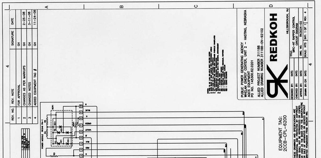
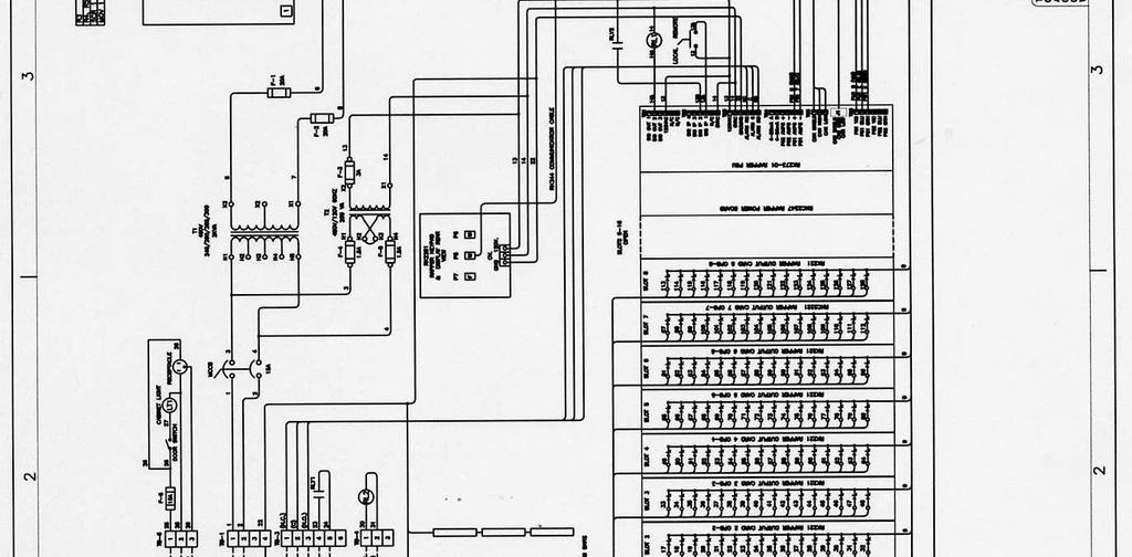
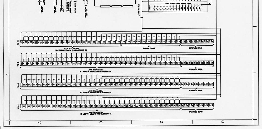
49 APPENDIX III Control and Component Drawings The following are the control and components drawings for the MTC-NT rapper control: Typical MRC-NT Rapper Control Circuit Drawing Typical MRC-NT Rapper Control General Arrangement RK2281 MTC-NT Flush Keyboard and Display Outline RK2273 MRC-NT Power Supply Board Outline RK2247 MRC-NT Power Board Outline RK2221 MRC-NT Output Board Outline RK2346 MRC-NT Power Module Outline The drawings themselves can be found on the following pages. Redkoh Industries Page 49 of 56
50 Redkoh Industries Page 50 of 56

51 Redkoh Industries Page 51 of 56
52 Redkoh Industries Page 52 of 56
53 Redkoh Industries Page 53 of 56

54 MRC-NT Rapper Control Operating Manual Redkoh Industries Page 54 of 56

55 MRC-NT Rapper Control Operating Manual Redkoh Industries Page 55 of 56

56 MRC-NT Rapper Control Operating Manual Redkoh Industries Page 56 of 56
CAN-Transceiver Data Register Map MODBUS Slave RTU
 MODBUS Slave RTU V1.40 Table of Contents INTRODUCTION... 3 CAN TRANSCEIVER GLOBAL DATA... 3 OPTIONAL DIGITAL INPUTS... 3 AVC (TR CONTROL) REGISTER BASE ADDRESSES... 3 AVC MODBUS REGISTER DEFINITION...
Keypad LCD (software version 3.10) CA-10 plus
 CA-10 plus") PROGRAMMING AND INSTALLATION MANUAL Keypad LCD (software version 3.10) CA-10 plus GDAŃSK ca10plci_e 09/03 WARNING Due to safety reasons, alarm system should be installed by qualified personnel only. Because
PROGRAMMING AND INSTALLATION MANUAL Keypad LCD (software version 3.10) CA-10 plus GDAŃSK ca10plci_e 09/03 WARNING Due to safety reasons, alarm system should be installed by qualified personnel only. Because
212iL Rev. 1.1
 212iL 1 International Electronics, Inc. 427 Turnpike Street Canton, Massachusetts 02021 212iL (illuminated Luxury) Keypad Single Unit Keypad- Control Installation Manual Features: 120 User Capability Illuminated
PROGRAMMING AND INSTALLATION MANUAL
 PROGRAMMING AND INSTALLATION MANUAL Keypad LCD-S (software version 3.10) CA-10 plus GDAŃSK ca10plci_s_e 09/03 WARNING Due to safety reasons, alarm system should be installed by qualified personnel only.
SERIES CMT CARBON MONOXIDE GAS TRANSMITTER
 SERIES CMT CARBON MONOXIDE GAS TRANSMITTER INSTALLATION OPERATION AND MAINTENANCE MANUAL DWYER INTRUMENTS, INC. PO BOX 373, MICHIGAN CITY, IN. 46360 USA PHONE: 800-872-9141 FAX: 219-872-9057 Web: www.dwyer-inst.com
Keypad LCD-L (software version 3.10) CA-10 plus
 CA-10 plus") PROGRAMMING AND INSTALLATION MANUAL Keypad LCD-L (software version 3.10) CA-10 plus GDAŃSK ca10plci_l_e 09/03 WARNING Due to safety reasons, alarm system should be installed by qualified personnel only.
PROGRAMMING AND INSTALLATION MANUAL Keypad LCD-L (software version 3.10) CA-10 plus GDAŃSK ca10plci_l_e 09/03 WARNING Due to safety reasons, alarm system should be installed by qualified personnel only.
Model HM-535 Power Supply Installation and Service Instructions
 Model HM-535 Power Supply Installation and Service Instructions 430-535 0104 2004 Heritage MedCall, Inc SENTRY INSTALLATION & SERVICE INSTRUCTIONS POWER SUPPLY UNIT Model HM-535 IMPORTANT SAFETY INSTRUCTIONS
The timer has several functions: count-down timer with voice report; count-up timer without voice report; and talking clock.
 Instructions for Talking Up/Down Timer LIV-041-329-0001 Getting to know your timer: The timer has several functions: count-down timer with voice report; count-up timer without voice report; and talking
SYSTIMAX imvision Controller User Guide
 Issue 3 SYSTIMAX imvision Controller User Guide Table of Contents Overview... 2 Important Safety Instructions... 2 The imvision System... 3 ipatch Panel... 3 imvision Controller... 3 Ordering Panels in
MULTI-PURPOSE SELF-CONTAINED DIGITAL ACCESS CONTROL KEYPAD
 MULTI-PURPOSE SELF-CONTAINED DIGITAL ACCESS CONTROL PAD Programming & Installation Manual An Innovative Product Developed By: PROTECT - ON SYSTEMS LTD. MANUFACTURED BY: 20 R SINCE 1979 ADVANCED ELECTRONICS
ToroPCTM User s Manual
 Part No. 92797SL, Rev. A ToroPCTM User s Manual TM A UTOMATED C ONTROL E LECTRONICS Commercial Products The Toro Company 1992, 1993 This page is blank. FORM 92-797-SL, Rev. A ToroPC User s Manual This
Carefree-Security. Installation and programming instructions 1050A. Owner s Manual
 Carefree-Security Heavy Duty Commercial - Industrial Fully Sealed Digital Access Keypad Specially Designed for Gate Operators, Overhead Doors, Specialty Doors & Electric Door Locking Devices SINGLE OR
LC3 LIGHTING CONTROLLER OPERATIONS & MAINTENANCE MANUAL 2013 Dec
 LC3 LIGHTING CONTROLLER OPERATIONS & MAINTENANCE MANUAL 2013 Dec THETA LABS INC Aguila AZ 85320-0734 928-671-1885 www.thetalabs.com CONTENTS 1. DESCRIPTION & SPECIFICATIONS page 1.1 General 1 1.2 Mechanical
Pace Clock. For the System 6 Sports Timer Software User Guide. F873 rev
 Pace Clock For the System 6 Sports Timer Software User Guide F873 rev 20171114 Customer Service Department www.coloradotime.com Email: customerservice@coloradotime.com Phone: +1 970-667-1000 Toll Free
INTRODUCTION CT87E FEATURES AND CONTROLS
 INTRODUCTION The CT87E is a precision instrument used to monitor and record the presence or absence of voltage, light, or sound level such as what would be produced by an operating electric motor or compressor.
Manual Simatek Control Unit GFC 32
 Manual Simatek Control Unit GFC 32 Original instructions 1400004_GB Ver. 2014.01.09 Index 1. Main features 3 2. Technical features 3 3. Installation guidelines 4 4. Preliminary checks 5 5. Electrical connections
Back-UPS RS APC Back-UPS RS 800VA 120V Black
 Back-UPS RS APC Back-UPS RS 800VA 120V Black APC Back-UPS RS, 540 Watts / 800 VA,Input 120V / Output 120V Includes: CD with software, Cord management straps, Free trial of anti-virus : firewall : email
SC2000 MOTOR PROTECTION ELECTRONICS, INC. INSTRUCTION MANUAL. Phone: (407) Fax: (407) Vulcan Road Apopka, Florida 32703
 Fax: (407) Vulcan Road Apopka, Florida 32703") SC2000 INSTRUCTION MANUAL MOTOR PROTECTION ELECTRONICS, INC. 2464 Vulcan Road Apopka, Florida 32703 Phone: (407) 299-3825 Fax: (407) 294-9435 Operating Program Revision: 10 Revision Date: 1-9-12 STATION
SC2000 INSTRUCTION MANUAL MOTOR PROTECTION ELECTRONICS, INC. 2464 Vulcan Road Apopka, Florida 32703 Phone: (407) 299-3825 Fax: (407) 294-9435 Operating Program Revision: 10 Revision Date: 1-9-12 STATION
FlexPak 3000 Drive Operator Interface Module (OIM) User s Guide
 User s Guide") FlexPak 3000 Drive Operator Interface Module (OIM) User s Guide Instruction Manual D2-3344 The information in this manual is subject to change without notice. Throughout this manual, the following notes
FlexPak 3000 Drive Operator Interface Module (OIM) User s Guide Instruction Manual D2-3344 The information in this manual is subject to change without notice. Throughout this manual, the following notes
INSTRUCTION MANUAL. Model Dual Input RTD Thermometer. Measures two temperatures simultaneously. Dual RTD probe inputs
 INSTRUCTION MANUAL Model 421504 Dual Input RTD Thermometer Measures two temperatures simultaneously Dual RTD probe inputs Clock and Elapsed Timer functions Special functions include Data Hold, MIN/MAX/AVG,
Manual Control Unit GFC 32
 Manual Control Unit 1400004_EN/05.2017 Index 1. Main features 3 2. Technical features 3 3. Installation guidelines 4 4. Preliminary checks 5 5. Electrical connections 5 6. Settings 6 7. Remote control
CardMaster Programming Guide Rev CardMaster Operators Guide. CardMaster Installation Manual. CardMaster Service Guide
 CardMaster Programming Guide Rev 10.06.03 Related Manuals include: CardMaster Operators Guide CardMaster Installation Manual CardMaster Service Guide CardMaster RF Installation Manual Wireless Modem Setup
DGSZV-EP DIGITAL GALVANIC LONGITUDINAL DIFFERENTIAL PROTECTION. Application field
 DGSZV-EP DIGITAL GALVANIC LONGITUDINAL DIFFERENTIAL PROTECTION The digital galvanic longitudinal differential protection of type DGSZV-EP is part of device family named EuroProt. This short description
SC2000 MOTOR PROTECTION ELECTRONICS, INC. INSTRUCTION MANUAL. (407) Phone: Website:
 Phone: Website:") SC2000 INSTRUCTION MANUAL MOTOR PROTECTION ELECTRONICS, INC. 2464 Vulcan Road Apopka, Florida 32703 Phone: Website: (407) 299-3825 www.mpelectronics.com Operating Program Revision: 12 Revision Date: 8-27-14
SC2000 INSTRUCTION MANUAL MOTOR PROTECTION ELECTRONICS, INC. 2464 Vulcan Road Apopka, Florida 32703 Phone: Website: (407) 299-3825 www.mpelectronics.com Operating Program Revision: 12 Revision Date: 8-27-14
DG-800 Stand-Alone Proximity Reader Instruction Manual
 DG-800 Stand-Alone Proximity Reader Instruction Manual I. Features 1. Memory volume up to 1000+10 proximity cards/tokens and PINs with the programming time up to 0.5 seconds. 2. Access modes: a. Only Proximity
VANDAL RESISTANT BACK-LIT WEATHERPROOF ACCESS CONTROL KEYPAD
 VANDAL RESISTANT BACK-LIT WEATHERPROOF ACCESS CONTROL KEYPAD Post Mount Keypad Programming & Installation Manual 1. Connect Power 12V DC to 24V AC/DC to terminals (+) and (-) Post Mount Keypad Quick Start
SATA DVD/CD Duplicator Controller User s Manual
 SATA DVD/CD Duplicator Controller User s Manual Version 2.0 TABLE OF CONTS Chapter 1 Introduction 1 10. Setup 11 11. HDD Manager 13 LCD Front Panel Overview 1 o Start-up Menu 11 o Select Image 13 Hardware
Graphic Rapper Controller (GRC) User s Guide
 User s Guide") Graphic Rapper Controller (GRC) User s Guide Rev. 2.1 Revisions Rev. Date Author Description 1.0 11/2/99 Original 1.1 8/10/05 Added multiple rap feature 2.0 1/13/06 FGS Updated for new display screens
Graphic Rapper Controller (GRC) User s Guide Rev. 2.1 Revisions Rev. Date Author Description 1.0 11/2/99 Original 1.1 8/10/05 Added multiple rap feature 2.0 1/13/06 FGS Updated for new display screens
Dual channel temperature logger with two voltage inputs 0-5V Instruction Manual
 LOGGER S0541 Dual channel temperature logger with two voltage inputs 0-5V Instruction Manual Instruction Manual for use of S0541 logger Instrument is designed for measurement and record of temperature
output devices. connected to the controller. data communications link. relay systems. user program. MECH1500Quiz1ReviewVersion2 Name: Class: Date:
 Class: Date: MECH1500Quiz1ReviewVersion2 True/False Indicate whether the statement is true or false. 1. The number and type of I/Os cannot be changed in a fixed PLC. 2. In a PLC system, there is a physical
Manual Control Unit GFCD 16
 Manual Control Unit 1400002_EN/04.2017 Index 1. Main features 3 2. Technical features 3 3. Installation guidelines 4 4. Preliminary checks 5 5. Electrical connections 5 6. Filter taps 5 7. Settings 6 8.
Glossary access code alarm anemometer auto limits base screen central control mode Gloss
 access code A user assigned 3 digit code used to restrict unauthorized usage (reprogramming/control) of the controller. alarm An irrigation related "event" reported by the controller which requires operator
AMS Controls Model MP450Z
 AMS Controls Model MP450Z SHEAR 7 8 9 4 5 6 1 2 3 CAL * PRG RUN STOP 0.CE MP400 SERIES ENT LENGTH CONTROL SYSTEMS Push button and Front Panel Selector Switches SHEAR Run Stop The SHEAR button is an illuminated
SYSTEMAX 2014 MULTIVALVE ELECTRONIC CONTROLLER WITH DEMAND RECALL
 MULTIVALVE ELECTRONIC CONTROLLER WITH DEMAND RECALL Service Manual Table of Contents Item Page Introduction and General Description...3 Front Panel View and Description...3 Modes of Operation...4 Front
Installation and Operation Back-UPS BR1000G-IN / BR1500G-IN
 Installation and Operation Back-UPS BR1000G-IN / BR1500G-IN Important Safety Information Read the instructions carefully to become familiar with the equipment before trying to install, operate, service
DAS LCD ALPHA NUMERIC CODEPAD
 DAS LCD ALPHA NUMERIC CODEPAD Table of Contents 1. LCD Codepad Diagram... 2 2. Introduction... 3 3. Understanding Your LCD Codepad... 4-7 4. Changing User Codes... 8-9 5. Special Function Keys..... 10
Instruction Manual. ROYTRONIC EXCEL Series AD9 Programming Guide Electronic Metering Pumps
 Instruction Manual ROYTRONIC EXCEL Series AD9 Programming Guide Electronic Metering Pumps For file reference, please record the following data: Model No: Serial No: Installation Date: Installation Location:
Dual channel temperature logger with display Instruction Manual
 LOGGER S0122 Dual channel temperature logger with display Instruction Manual ie-log-s0122-05 Instruction manual for use of temperature logger S0122 Logger is designed for measurement and record of ambient
INSTRUCTION MANUAL STATION CONTROLLER SC1000 MOTOR PROTECTION ELECTRONICS, INC.
 INSTRUCTION MANUAL STATION CONTROLLER SC1000 MOTOR PROTECTION ELECTRONICS, INC. 2464 Vulcan Road, Apopka, Florida 32703 Phone: (407) 299-3825 Fax: (407) 294-9435 Revision Date: 9-11-08 Applications: Simplex,
Section 1 General Description. Section 3 How to Program Keypad. Section 2 Installation. CM-120TX Wireless Digital Keypads Installation Instructions
 CM-120TX Wireless Digital Keypads Installation Instructions Package Contents - (1) Keypad and faceplate assembly - (1) Foam gasket (CM-120W only) - (2) #6-32 x 1 S/S Phillips screws - (2) #6-32 x 1 Tamperproof
INSTALLATION INSTRUCTIONS Model 930 EntryCheck
 SECURITY DOOR CONTROLS 3580 Willow Lane, Westlake Village, CA 91361-4921 (805) 494-0622 Fax: (805) 494-8861 www.sdcsecurity.com E-mail: service@sdcsecurity.com INSTALLATION INSTRUCTIONS Model 930 EntryCheck
Series B9 and C9 Electronic Metering Pumps. Instruction Manual. Manual No : 1796 Rev. : D Rev. Date : 11/2015
 Series B9 and C9 Electronic Metering Pumps Manual No : 1796 Rev. : D Rev. Date : 11/2015 sales@novatech-usa.com www.novatech-usa.com Tel: (866) 433-6682 Fax: (866) 433-6684 Tel: (281) 359-8538 Fax: (281)
5450 NW 33rd Ave, Suite 104 Fort Lauderdale, FL Fruitland Ave Los Angeles, CA UM Channel Monitor.
 5450 NW 33rd Ave, Suite 104 Fort Lauderdale, FL 33309 3211 Fruitland Ave Los Angeles, CA 90058 UM-600 6-Channel Monitor Version 2 Installation and Operation Manual Rev. G P/N145F-12990 PCO 00007462 (c)
Temperature logger with display Instruction Manual
 LOGGER S0110 Temperature logger with display Instruction Manual Instruction manual for use of temperature logger S0110 Logger is designed for measurement and record of temperature from built-in internal
TABLE OF CONTENTS TABLE OF CONTENTS... 1 IMPORTANT SAFETY NOTICE...
 TABLE OF CONTENTS TABLE OF CONTENTS... 1 IMPORTANT SAFETY NOTICE... 2 1.0 General Information... 3 1.1 System Components... 3 1.2 Specifications... 3 1.2.1 Torque Ranges... 3 1.2.2 Electrical Specifications...
6-Channel Monitor. Installation and Operation Manual
 3211 Fruitland Ave Los Angeles, CA 90058 Catalyst Monitor 6-Channel Monitor Version 2 Installation and Operation Manual Rev. H P/N145F-12964 PCO - 00009743 (c) Copyright 2015, Barksdale, Inc. All Rights
GARNET. SEELEVEL II TM Tank Monitor INSTRUMENTS LTD. Model 709 Owner s Manual IMPORTANT OPERATOR INFORMATION DATE INSTALLED: SERIAL NUMBER:
 GARNET INSTRUMENTS LTD. SEELEVEL II TM Tank Monitor Model 709 Owner s Manual IMPORTANT OPERATOR INFORMATION DATE INSTALLED: SERIAL NUMBER: Signal Level Sender Height Black Water Tank Grey Water Tank Fresh
IMPORTANT SAFETY INSTRUCTIONS SAVE THESE INSTRUCTIONS
 IMPORTANT SAFETY INSTRUCTIONS IMPORTANT SAFETY INSTRUCTIONS SAVE THESE INSTRUCTIONS WARNING (SAVE THESE INSTRUCTIONS): This manual contains important instructions that should be followed during installation
Dual channel temperature logger with two binary inputs and LCD display Instruction Manual
 LOGGER S0841 Dual channel temperature logger with two binary inputs and LCD display Instruction Manual Instruction Manual for use of S0841 logger Instrument is designed for measurement and record of temperature
REMOTE KEYPAD with NFC Tag (KPT-32N, KPT-32N-F1)
") REMOTE KEYPAD with NFC Tag (KPT-32N, KPT-32N-F1) April 01st, 2016 Identifying the Parts 1. Siren 2. Orange LED: Home Arm Key 3. Red LED: Away Arm Key 4. Panic Alarm (if enabled) - Press both 1 and 3 to
REMOTE KEYPAD with NFC Tag (KPT-32N, KPT-32N-F1) April 01st, 2016 Identifying the Parts 1. Siren 2. Orange LED: Home Arm Key 3. Red LED: Away Arm Key 4. Panic Alarm (if enabled) - Press both 1 and 3 to
Installation and User Instructions
 7KH$$QDORJ,QWHUIDFH0RGXOH (for connection with the 646D+M and 644D+M Telephones) Installation and User Instructions [This module meets U.S. Analog Telephone Interface Requirements.] Document Ordering No.
Exercise 2. Single Bus Scheme EXERCISE OBJECTIVE DISCUSSION OUTLINE. The single bus scheme DISCUSSION
 Exercise 2 Single Bus Scheme EXERCISE OBJECTIVE When you have completed this exercise, you will be familiar with electric power substations using the single bus scheme with bus section circuit breakers.
SK-3133-PPQ Heavy-Duty Outdoor Access Control Keypad with Proximity Reader
 SK-3133-PPQ Heavy-Duty Outdoor Access Control Keypad with Proximity Reader Features: Rugged construction heavy-duty stainless steel faceplate with coated steel housing Built-in proximity card reader 12~24
Loup Electronics Planter Monitor LPM II. User Guide
 Loup Electronics Planter Monitor LPM II User Guide TABLE OF CONTENTS 1. I TRODUCTIO...4 2. LIQUID CRYSTAL DISPLAYS...8 2.1 UPPER LCD...8 2.2 LOWER LCD...9 3. OPERATI G SPECIFICATIO...10 3.1 OPERATING MODES...10
9212i INSTALLATION. Stand-Alone Keypad. Instructions
 INSTALLATION 9212i Stand-Alone Keypad Instructions Features: 4 Independent Outputs 4 Independent Timers All Outputs Assignable by Code On board 5 Amp Form C Relay 120 Users Remote Triggering Input Keypad
GSM AD05 Slave GSM Auto Dialer- Instruction Manual
 GSM AD05 Slave GSM Auto Dialer- Instruction Manual Please read these instructions before you start the installation Features LCD display Programmable 9 x 32 digit phone numbers for each trigger. 10 second
MC LINX 1 & 2 USER S GUIDE. 1 Description. 2 Specifications MC LINX 2 MC LINX 1 PROGRAMMABLE RELAY MODULE. INCR & FUNCT Push Buttons
 MC LX 1 & 2 USER S GUIDE PROGRAMMABLE RELAY MODULE 1 Description The MC Linx (PN: 10MCLX1 and 10MCLX2) is a programmable relay module that may be used for multiple applications. The module provides removable
DLRO 200 High Current, Low Resistance Ohmmeter
 M DLRO 200 High Current, Low Resistance Ohmmeter USER MANUAL GSAFETY WARNINGS THESE SAFETY WARNINGS MUST BE READ AND UNDERSTOOD BEFORE THE INSTRUMENT IS USED. n DLRO200 is supplied without a plug terminating
User Manual Digi-Sense 12-Channel Benchtop Data Logging Thermocouple Thermometer
 User Manual Digi-Sense 12-Channel Benchtop Data Logging Thermocouple Thermometer Model: 92000-01 THE STANDARD IN PRECISION MEASUREMENT Table of Contents Introduction... 3 Unpacking... 3 Initial Setup...3
39E Electronic Combination Lock SETUP INSTRUCTIONS
 The ComboGard Pro Lock has three states of operation: Factory Default, Manual Setup, and Active. ComboGard Pro locks are shipped from LA GARD in Factory Default state without Users or features enabled.
HI-POT TESTER. User s Manual
 HI-POT TESTER 7620 User s Manual Contents 1. Before Use... 1.1Electric Shock Avoidance... 4 1.2 Grounding... 4 1.3 AC Power Supply... 4 1.4 Connecting Test Leads... 4 1.5 Warm Up... 4 1.6 External Control...
7000 SERIES Power Switching Solutions. Closed Transition Transfer Switching. Delayed Transition Transfer Switching
 7000 SERIES Power Switching Solutions Fig. 2: Four pole, Closed Transition Switch rated 1000 Amperes in Type 1 enclosure. Closed Transition Switching Closed Transition Switches feature main contacts that
AP41 / AP81 SERIES TIME SWITCHES
 FN:AP41_81M1.DOC AP41 / AP81 SERIES TIME SWITCHES AP41 AP81 TABLE OF CONTENTS INTRODUCTION 2 SPECIFICATIONS 2 INSTALLATION 5 FRONT PANEL DESCRIPTION 7 OPERATION 8 Filling out the Program Record Sheet 8
TABLE OF CONTENTS TABLE OF CONTENTS... 1 MANUAL REVISION HISTORY... 2 IMPORTANT SAFETY NOTICE...
 TABLE OF CONTENTS TABLE OF CONTENTS... 1 MANUAL REVISION HISTORY... 2 IMPORTANT SAFETY NOTICE... 3 1.0 General Information... 5 1.1 System Components... 5 1.2 Specifications... 5 1.2.1 Torque Ranges...
Operating Manual QUESTOR
 QUESTOR Programming and Activation AS 271 and AS 270 Document: KSW3s527.0003 / en 2010.08 Edition: August 2010 QUESTOR TABLE OF CONTENT 1 Product description EN-4 1.1 Purpose... EN-4 1.1.1 AS 271 programming
QUICK START. Installation & Programming Guide
 QUICK START Installation & Programming Guide PRECAUTIONS READ AND FOLLOW ALL SAFETY INSTRUCTIONS. CAUTION - RISK OF ELECTRICAL SHOCK. To prevent electrical shock, turn off power at the circuit breaker
ZX-50 SRT Seed Research Technology Portable Grain Analyzer with AutoBIAS. User s Manual Version 4.1
 ZX-50 SRT Seed Research Technology Portable Grain Analyzer with AutoBIAS User s Manual Version 4.1 This manual provides you the information needed to operate the ZX-50 SRT Portable Grain Analyzer. ZELTEX,
Installation and Operation Manual Back-UPS BR900G-RS
 Installation and Operation Manual Back-UPS BR900G-RS Inventory Safety bu001a This unit is intended for indoor use only. Do not operate this unit in direct sunlight, in contact with fluids, or where there
Pretest Programmable Logic Controllers. Unit 1, Task 1
 Pretest Programmable Logic Controllers Unit 1, Task 1 1. What is a PLC? 2. What are the four main components of a PLC? 3. What is a discrete device? 4. What is a pulse-generating device? 5. What term is
Draper Commissioner User Manual
 Draper Commissioner User Manual Table of Contents Table of Contents...I 1. Getting Started...1 1.1 Initial Startup...1 1.2 Draper Commissioner Startup...1 1.3 Top Panel...1 2. Configuration Screens...2
MIRRIN. Multi-Channel Load Logger MODEL: LL400 User Manual 1 GETTING STARTED INTRODUCTION CONNECTIONS
 Contents MIRRIN Multi-Channel Load Logger MODEL: LL400 User Manual 1 GETTING STARTED... 3 1.1 INTRODUCTION... 3 1.2 CONNECTIONS... 3 1.3 KIT 5 1.3.1 Accessories... 5 1.3.2 Options... 5 1.4 POWER MODES...
CORTEX Microcontroller and Joystick User Guide
 This is a User Guide for using the VEX CORTEX Microcontroller and VEX Joystick. Refer to the VEX Wiki (http://www.vexforum.com/wiki/index.php/vex_cortex_microcontroller) for updates to this document. 1.
Installation and Operation Back-UPS Pro BR700G-TW
 Installation and Operation Back-UPS Pro BR700G-TW Inventory Safety Do not install the UPS in direct sunlight, in excessive heat, humidity, or in contact with fluids. Do not connect a laser printer or hair
SC1000 MOTOR PROTECTION ELECTRONICS, INC. INSTRUCTION MANUAL. Phone: (407) Fax: (407) Vulcan Road Apopka, Florida 32703
 Fax: (407) Vulcan Road Apopka, Florida 32703") SC1000 INSTRUCTION MANUAL MOTOR PROTECTION ELECTRONICS, INC. 2464 Vulcan Road Apopka, Florida 32703 Phone: (407) 299-3825 Fax: (407) 294-9435 Operating Program Revision: 8 Revision Date: 5-16-11 STATION
SC1000 INSTRUCTION MANUAL MOTOR PROTECTION ELECTRONICS, INC. 2464 Vulcan Road Apopka, Florida 32703 Phone: (407) 299-3825 Fax: (407) 294-9435 Operating Program Revision: 8 Revision Date: 5-16-11 STATION
FERGUSON BEAUREGARD. RTU-5000 Configurator User Manual
 FERGUSON BEAUREGARD RTU-5000 Configurator User Manual FERGUSON BEAUREGARD RTU-5000 Configurator User Manual The Ferguson Beauregard RTU-5000 Configurator program and manuals are Copyright 1997-2004 by
INTRODUCTION. Thank you for purchasing a Qualitel product which adopts excellent workmanship and exceptional reliability.
 1 INTRODUCTION Thank you for purchasing a Qualitel product which adopts excellent workmanship and exceptional reliability. Your telephone is designed to give you flexibility in use and high quality performance.
Graphic Rapper Controller (GRC) User s Guide
 User s Guide") Graphic Rapper Controller (GRC) User s Guide Rev. 3.1 Revisions Rev. Date Author Description 1.0 11/2/99 Original 1.1 8/10/05 Added multiple rap feature 2.0 1/13/06 FGS Updated for new display screens
Graphic Rapper Controller (GRC) User s Guide Rev. 3.1 Revisions Rev. Date Author Description 1.0 11/2/99 Original 1.1 8/10/05 Added multiple rap feature 2.0 1/13/06 FGS Updated for new display screens
ZX-50IQ Portable Grain Analyzer with AutoBIAS. User s Manual
 ZX-50IQ Portable Grain Analyzer with AutoBIAS User s Manual Version 4.1 This manual provides you the information needed to operate the ZX-50IQ Portable Grain Analyzer. ZELTEX, INC. 130 Western Maryland
PROGRAMMING AND USE INSTRUCTIONS FOR THE OVATION SYSTEM
 Doc. 6001012 Rev B PROGRAMMING AND USE INSTRUCTIONS FOR THE OVATION SYSTEM ALPHA COMMUNICATIONS 42 Central Drive Farmingdale NY 11735-1202 Phone: 631-777-5500 - Fax: 631-777-5599 IMPORTANT NOTICE If the
GETTING STARTED. Installing the System 2000 Hardware. Configuring Your System 2000 Hardware. Troubleshooting. Configuring Your System 2000 Network
 SYSTEM 2000 GETTING STARTED Installing the System 2000 Hardware Whether you are upgrade an existing System 2, or this is a brand new installation, there will be some hardware installation involved. We
Press the PEN HOME key to move the pen(s) to the outside of the chart. The pen(s) is automatically raised off the chart.
 to the outside of the chart. The pen(s) is automatically raised off the chart.") DICKSON GETTING STARTED 7-day chart rotation 0 to 100 o F KT8P0/2/3 & KT856 Remote Sensing Temperature Recorder QUICK START 1. Remove the protective pen cap(s). 2. Connect Probe(s): a. KT8P0/2/3: Make
DICKSON GETTING STARTED 7-day chart rotation 0 to 100 o F KT8P0/2/3 & KT856 Remote Sensing Temperature Recorder QUICK START 1. Remove the protective pen cap(s). 2. Connect Probe(s): a. KT8P0/2/3: Make
DLA. DMX512 Analyzer. DLA Users Manual SV2_00 B.lwp copyright ELM Video Technology, Inc.
 DLA DMX512 Analyzer DLA DLA-HH 1 Table Of Contents IMPORTANT SAFEGUARDS... 2 DLA OVERVIEW... 3 CONNECTION... 3 OPERATION... 3 HARDWARE SETUP... 4 DLA-HH (PORTABLE) LAYOUT... 4 CHASSIS LAYOUT... 4 DLA MENU
Installation and operation manual ReciFlow Gas
 Installation and operation manual ReciFlow Gas 1 1. Measurement principle... 3 2. Installation... 5 3. Operation... 7 4. Electrical interfaces... 11 5. Communication protocol... 14 6. Software update and
121000TP227S USER'S MANUAL
 121000TP227S USER'S MANUAL TABLE OF CONTENTS FEATURE LIST SAFETY INSTRUCTIONS INTRODUCTION LOCATION OF CONTROLS FUNCTION BUTTONS MENU SETTINGS CALLER ID INFORMATION DISPLAY MESSAGES CALLER ID SYSTEM OPERATION
MODEL 3312 LED
 INSTALLATION INSTRUCTIONS FOR MODEL 3312 LED www.sportablescoreboards.com 1 Table of Contents DISCRIPTION... 3 THE SCOREBOARD SYSTEM SHOULD INCLUDE THE FOLLOWING PARTS:... 3 INSTRUCTIONS FOR REPORTING
GOLD SERIES DVD/CD Duplicator Manual
 GOLD SERIES DVD/CD Duplicator Manual User s Manual Version 3.0 0 TABLE OF CONTENTS Introduction 2 Setup 11 LCD Front Panel Overview 2 o Auto Start Time 11 Menu Overview 3-5 o Display Mode 12 Functions
Dim levels for each system output may be controlled by any of the following methods:
 Applied Electronics Bravo Series Dimming System Rack-Mount Architectural l SA12/2400A and l SA12/2400E Setup and Operation Instructions 1.0 Scope This document details the setup and operation requirements
Installation, Operation Instructions
 P4-Series ProCE LPG ELECTRONIC DISPENSER CALCULATOR, VER 4.33A/B/C Installation, Operation Instructions Page 1 Table of Contents ELECTRONIC PUMP CALCULATOR PROGRAMMING... 4 1.0 ATTENDANT MENU... 7 1.1
THE OVAL CONTROL OPERATING GUIDE MODEL SETR-60 and SETR-61
 THE OVAL CONTROL OPERATING GUIDE MODEL SETR-60 and SETR-61 1. Power up the boat s main DC service and turn on the trim tab circuit breaker. The Oval" will come up on standby but no LED s will be lit. 2.
Thank you for purchasing our product which adopts excellent workmanship and exceptional reliability.
 INTRODUCTION Thank you for purchasing our product which adopts excellent workmanship and exceptional reliability. Your telephone is designed to give you flexibility in use and high quality performance.
Level-Lance Model 5400A
 Sales Manual Section 100 PRODUCT SPECIFICATION 5400A GENERAL DESCRIPTION The ROBERTSHAW Level-Lance Model 5400A is a microprocessor based, multi-point On-Off capacitance type level detection system. Utilizing
Power Connections: Basic Wiring:
 Power Connections: The CFW10 Quick Start Guide is a supplement to help get the CFW10 started quickly using the most common installation and configuration options. This CFW10 Quick Start Guide is not meant
GV3000/SE Operator Interface Module (OIM) User Guide Version 2.0 M/N 2RK3000
 User Guide Version 2.0 M/N 2RK3000") GV3000/SE Operator Interface Module (OIM) User Guide Version 2.0 M/N 2RK3000 Instruction Manual D2-3342-2 The information in this manual is subject to change without notice. Throughout this manual, the
GV3000/SE Operator Interface Module (OIM) User Guide Version 2.0 M/N 2RK3000 Instruction Manual D2-3342-2 The information in this manual is subject to change without notice. Throughout this manual, the
Fagor Automation S. Coop. NV-10/11 NV-20/21 NV-300/301M. Operating Manual. Manual code: Manual version: 0410 Software version: 3.
 Fagor Automation S. Coop. NV-10/11 NV-20/21 NV-300/301M Operating Manual Manual code: 14460044 Manual version: 0410 Software version: 3.xx INDEX 1 Unit description...3 1.1 Front panel... 3 1.2 Rear panel
User Manual Back-UPS BE650MC
 User Manual Back-UPS BE650MC Inventory Back-UPS ES 650 bu075b This unit is intended for indoor use only. Do not operate this unit in direct sunlight, in contact with fluids, or where there is excessive
Intelli-Tank. Water/foam tank level display with Drip Empty. Revision log. 2. Calibration. 10. Dim function. 13. Self test. 13. Passwords.
 Intelli-Tank Water/foam tank level display with Drip Empty Contents. 1 Revision log. 2 Overview. 3 Operation. 4 Installation. 6 Wiring. 8 Calibration. 10 Dim function. 13 Self test. 13 Passwords. 14 Troubleshooting.
Model High -Tech Programmable Controller. Operating Instructions
 Model High -Tech Programmable Controller Operating Instructions Version 2 Yamato Scientific Co., Ltd 1.. INTRODUCTION...... 2 Explanation of Character on the display.........3 2. INPUTTING, EDITION AND
SK-1011-SQ Digital Access Keypad with 5A Relay Output
 User Operation for the SK--SQ. Using the User Codes: A. User codes operate the door (4-8 digits long). Press u u u u B. The key must also be pressed if the keypad is in manual-entry mode. Press u u u u
Wireless Expander Eclipse WL Installation and Programming Manual
 Wireless Expander Eclipse WL Installation and Programming Manual 1. General Information Eclipse WL is a wireless expander module designed for building of hybrid systems with wired control panels Eclipse
TDC+ CONTROLLER. Programming Guide
 TDC+ CONTROLLER Programming Guide TABLE OF CONTENTS CHAPTER 1: BASIC CONTROLLER PROGRAMMING... 4 I. CONTROLLER SETUP... 4 UTILITY Time & Day Edit Mode... 4 UTILITY Day Change Hour Edit Mode... 6 UTILITY