Lab 4: Trajectory Following 1
|
|
|
- Vivian Haynes
- 6 years ago
- Views:
Transcription

1 Lab 4: Trajectory Following 1

2 Prelab Familiarize yourself with how the LabVIEW program works It is XYposition_control1.4.vi Located in Lab4_LabVIEW.zip on the Stellar page 2
3 Optional prelab: create your own trajectory It is possible (and optional) to create your own trajectory using Matlab Download and unzip Lab4_Matlab_optional.zip Open up SmoothSplineCurve.m This program allows you to open up an image and click points on the image. Then, it interpolates and smoothes the trajectory of points. Next, create an image file with the curve you d like to follow. Skoltech.png is provided as an example Enter the image file name in the Matlab program an run it Click the trajectory of points you d like to follow Save the X and Y vectors to a *.txt file An example trajectory file is TrajectoryS6.txt in Lab4_LabVIEW.zip Load it onto your myrio s tmp folder by following the instructions provided later in this lab Note: you will need to scale your trajectory so that it fits within the XY stage s ~2cm x 2cm workspace 3

4 In lab: Step 1: assemble two kits into a twoaxis stage 4
 Kit 2 Kit 1 Aluminum plate should remain attached, but is omitted in these photos for")
5 Combine the parts from your team s two kits Disassemble two kits to the level shown in the photo NOTE: keep your aluminum plate attached to the bottom of kit 1 (The plate is omitted from these photos for clarity) Kit 2 Kit 1 Aluminum plate should remain attached, but is omitted in these photos for clarity

6 Attach Base 2 to Carriage 1 with two M2.5x8 screws Insert hex driver through holes to access screws 6

7 Attach Coil 1 to Base 2 using two #8 screws You may have to rotate Coil 2 so that the holes line up. Make sure VCA wires are sticking out to the right as viewed in this picture 7

8 Place Voice Coil 2 in position on Base 2 and attach magnet using two #8 screws 8

9 Attach Coil Support 2 to Carriage 2 using two M2.5x6 screws 9

10 Attach the coil to the coil support with two #8 screws 10
 Line up the encoder with")

11 Orient one encoder so that the pins are towards the base, as shown in the left photo (from Lab 1) Line up the encoder with the forward two mounting holes Attach encoder to base using two M2.5x14 screws Three holes Pins are towards base Two forward holes 11

12 Carefully place code strip in between the code strip support and the coil support bracket with the concave side facing towards the voice coil Tighten in place 12

13 Using two M2.5 screws, attach the two halves of the code strip support as shown in the photo 13

14 Affix the code strip support assembly to the back of Base 2, as shown 14


15 Place the other encoder against Base 1 with the pins away from the base Line up the holes with the rear two holes Secure in place with two M2.5x14 screws Pins away from base Three holes 15


16 Carefully place the code strip in the clamp assembly with the concave side facing towards Base 1 Line it up as shown in the left photo Tighten in place ~8mm 16
17 Now you re done assembling the 2-axis stage! 17

18 Attaching the pen writing assembly Fully insert your pen into the hole and tighten the four screws Attach the assembly to your 2-axis stage using four M2.5x8 screws 18

19 Find a flat, rigid object whose height is a few millimeters above the bottom of the pen, as shown. Tape a clean piece of paper to the object ~1-3mm Now you re done with assembly! 19


20 Step 2: wire up the second voice coil and motor driver Follow the same process as in Lab 1, but connect the five signals (PWM, INA, INB, ENC.A, and ENC.B) to myrio s Channel B 20
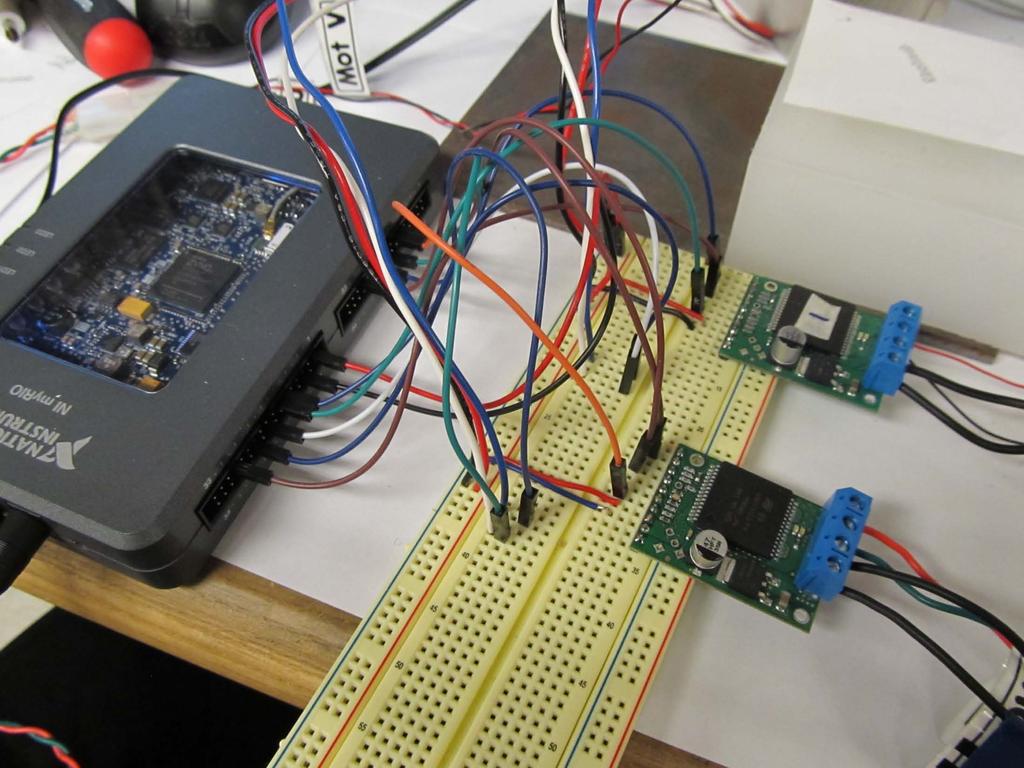
21 21
22 Step 3: control with LabVIEW Plug in the AC adapters for the myrio and motor driver carriers Connect the myrio to your computer with the USB cable and open up your myrio project Download Lab4_LabVIEW.zip from the Stellar page Drag XYposition_control1.4.vi into your myrio project Double-click it to open it up 22
 Username = admin, pw = (blank) Drag the text file")
23 Load the trajectory file onto your myrio using WebDAV Follow Steps 1-9 here: 57B6C0071D025#windows7 Note: you may need to temporarily turn off windows firewall Hostname: (see next page) Username = admin, pw = (blank) Drag the text file TrajectoryS6.txt into the tmp folder Takes 1 or 2 minutes If a window pops up that says Are you sure you want to copy this file without its properties?, click Yes 23

24 Hostname In my case, this is the folder address that I ll need to use when I Map Network Drive: 24

25 If you see a window that says Windows cannot access click Cancel. You probably need to power cycle the myrio. To do so, Unplug the myrio s USB connector from your computer Unplug power to the myrio Reconnect power to the myrio Wait for the myrio s Status LED to go from purple to off Plug the myrio s USB into your computer Try to reconnect using Map Network Drive 25

26 Zeroing the encoders We want the encoders to read zero at the center of their range of motion. To do this, Go back to your LabVIEW program and press run Push the actuators so that they are both fully compressed, as shown 26
27 With the actuators fully compressed, zero the encoders in your LabVIEW program Be sure to unpress each Zero Encoder button so that it does not continuously reset the encoder 27

28 Now, move both actuators by hand so that they are both at a position of about 14,000μm (the center of their range of travel). Position is displayed in LabVIEW, as highlighted in the photo on the following page Zero both encoders again Now your encoders will read zero when the device it at the center of its range of motion 28
29 29
30 Enabling the motors Now your stage is ready to start writing, but first we need to enable the motors The trajectory is being continuously read and loaded, but at this point, the motors are disabled When we enable one of the motors, it will rapidly move to follow the trajectory To prevent the recoil from potentially knocking the stage off of its stand, first firmly grasp voice coil 1, as shown on the next page (Alternatively, you can place your voice coil stage on a rigid object ~5cm tall, then clamp it in place using a C-clamp to sandwich the aluminum plate, 5cm object, and table.) 30

31 Hold this magnet when you enable position control. This will prevent the device from falling over. Do the same when you enable axis 2. 31
32 While grasping the magnet of voice coil 1 with one hand, use the other hand to toggle the VCA 1 control on/off switch to ON VCA 1 enable switch 32

33 Do the same for voice coil 2 VCA 2 enable switch 33

34 Now the motors should be following the trajectory and you re ready to start writing Lift up the tip of the pen and slide the writing surface underneath it. (Or, carefully tip the entire assembly up and slide the writing surface underneath) Release pen so that it makes good contact with the paper 34
35 Sit back and enjoy the show! 35
36 Press the Pause button to pause/unpause motion 36
37 Press the STOP button to stop motion 37
38 Potentially necessary: change the PID gains to improve performance Because following a trajectory is the same as following a series of sequential steps, having a good step response leads to good trajectory following. The default PID gains have been chosen to provide reasonably good trajectory following. You ll notice that they re close to the PID gains we used in Lab 3 Feel free to try different PID gains if you would like to improve the quality of the trajectory following 38

39 Potentially necessary: inverting the axis directions Potentially, you might find that the writing is mirrored. If that happens, try inverting the VCA1gain or VCA2gain above the Stop button 39

40 Optional: speed up or slow down You can speed up or slow down the writing speed by changing the parameter labeled C, which is below the Stop button You can see what C does by studying the LabVIEW block diagram 40
41 Checkoffs Demonstrate the assembled two-axis stage Demonstrate closed loop position control with both axes Demonstrate trajectory following Be ready to explain how the LabVIEW program works 41
Page
 Page 2... 3... 4... 5-6... 7-8... 9... 10... 11-12... 13... 14... 15... Index, Foreword Product Overview Preparation for Assembly Installing the Motherboard Installing the Passive CPU Cooler Installing
Z-Truck (Vertical Moving) Z-truck Flag. Y-Truck (Horizontal Moving) FIGURE 1: VIEW OF THE Z-TRUCK. Flexshaft Assembly
 Z-truck Flag. Y-Truck (Horizontal Moving) FIGURE 1: VIEW OF THE Z-TRUCK. Flexshaft Assembly") Replacing the LCD Cable To remove and replace the LCD Cable you will need the following tools: #2 Phillips screwdriver (magnetic tip preferred) Socket wrench with 10mm socket Removing the Side Panel 1.
Replacing the LCD Cable To remove and replace the LCD Cable you will need the following tools: #2 Phillips screwdriver (magnetic tip preferred) Socket wrench with 10mm socket Removing the Side Panel 1.
CIB 3047 (14B) 10-Button Voice Terminal Fixed Desk Stand and Wall Mount (32007)
 10-Button Voice Terminal Fixed Desk Stand and Wall Mount (32007)") CIB 3047 (14B) 10-Button Voice Terminal Fixed Desk Stand and Wall Mount (32007) CIB 3047 Comcode 845-659-325 Issue 1 CIB 3047 (14B) 10-Button Voice Terminal Fixed Desk Stand and Wall Mount (32007) This
CIB 3047 (14B) 10-Button Voice Terminal Fixed Desk Stand and Wall Mount (32007) CIB 3047 Comcode 845-659-325 Issue 1 CIB 3047 (14B) 10-Button Voice Terminal Fixed Desk Stand and Wall Mount (32007) This
Sit-Stand Monitor Arm
 Sit-Stand Monitor Arm Product ID: ARMSTSCP1 This sit-stand monitor arm transforms your desk or tabletop into an ergonomic workstation. The monitor arm features a keyboard tray and easy height adjustment
Guide for using HddSurgery head change tools:
 Page 1 of 15 Guide for using HddSurgery head change tools: HDDS Sea 7200.11/ES.2 p2 (2 platters) HDDS Sea 7200.11/.12/LP/ES.2 p3-4 (3 or 4 platters) Page 2 of 15 Table of contents: 1. Introduction.. page
CAMERA ASSEMBLY. Removal/Replacement of the Camera Box Assembly APR-CA. Install Camera Assembly. Remove Camera Assembly
 CAMERA ASSEMBLY Removal/Replacement of the Camera Box Assembly APR-CA REQUIRED TOOLS: 9/64 hex key Small flat-tip screwdriver Remove Camera Assembly camera 1. Locate the camera assembly underneath the
Page Foreword
 Page 2... 3... 4... 5-6... 7-8... 9... 10... 11... 12... 13... 14... 15... Index, Foreword Product Overview Preparing for Assembly Installing the Motherboard Installing the CPU Cooler Installing PSU &
Removal and Installation8
 8 Screw Types 8-4 Top Cover Assembly 8-5 Left Hand Cover 8-6 Right Hand Cover 8-10 Front Panel Assembly 8-14 Left Rear Cover 8-15 Right Rear Cover 8-16 Extension Cover (60" Model only) 8-17 Media Lever
Page
 Page 2... 3... 4... 5-6... 7... 8... 9-11... 12... 13... 14-15... Index, Foreword Product Overview Preparation for Assembly Installing the Motherboard Installing Case Fan & Optional IRRC Wiring Diagram
Written By: Walter Galan
 imac Intel 17" Power Supply Replacement Written By: Walter Galan ifixit CC BY-NC-SA www.ifixit.com Page 1 of 18 INTRODUCTION Power hungry? Keep those electrons flowing by replacing your power supply. TOOLS:
Addendum to the Actalyst Interactive Digital Signage Installation and User s Guide
 Addendum to the Actalyst Interactive Digital Signage Installation and User s Guide This addendum contains information about the Actalyst Interactive Overlay that has changed since the release of the Actalyst
LED Lighting Kit For Elara NanoEdge Fixed Frame. Installation Guide. Attention: Read this guide before assembling your screen.
 LED Lighting Kit For Elara NanoEdge Fixed Frame Installation Guide Attention: Read this guide before assembling your screen. INTRODUCTION GETTING STARTED WARNING - Sharp Edges This product may contain
PH-M3x5. Contents. Page
 Page 2... 3... 4... 5... 6-7... 8... 9.............. 10-12... 13... 14... 15... Contents Index, Message, Introduction Product Overview Preparation for Assembly Installing the Motherboard Installing the
Nov. 07, 2013 p. 5 - changed the B axis unit value to from Changed by Randy per Frank s request.
 Correction notes Nov. 07, 2013 p. 5 - changed the B axis unit value to 45.1389 from 40.0000. Changed by Randy per Frank s request. Jan. 22, 2018 p. 5 - changed the B axis unit value and corresponding picture
Written By: Walter Galan
 iphone 6 Plus Front Panel Replacement Replace the Front Panel in your iphone 6 Plus. Written By: Walter Galan ifixit CC BY-NC-SA www.ifixit.com Page 1 of 27 INTRODUCTION Use this guide to strip and replace
Mac Mini Mid 2010 SSD Installation
 Mac Mini Mid 2010 SSD Installation Replace your Mac Mini Mid 2010's hard drive for more storage space and an increase in speed. Written By: Dozuki System 2017 guides.crucial.com Page 1 of 15 INTRODUCTION
PH-M3x5. Contents. Page COPYRIGHT NOTICE
 Page 2... 3... 4... 5-6... 6-7... 8... 9.............. 10-12... 13... 14... 15... Contents Index, Message, Introduction Product Overview Preparation for Assembly Installing the Motherboard Installing the
INSTRUCTIONS FOR THE INSTALLATION OF THE INFINITY "L" DISPLAY HOOD (INTO PREVIOUSLY INSTALLED INFINITY "L" SYSTEMS)
") Doc. 6001025 Rev B INSTRUCTIONS FOR THE INSTALLATION OF THE INFINITY "L" DISPLAY HOOD (INTO PREVIOUSLY INSTALLED INFINITY "L" SYSTEMS) Rev. B Doc. 6001025 Page 1 of 13 IMPORTANT NOTICE This document covers
Doc. 6001025 Rev B INSTRUCTIONS FOR THE INSTALLATION OF THE INFINITY "L" DISPLAY HOOD (INTO PREVIOUSLY INSTALLED INFINITY "L" SYSTEMS) Rev. B Doc. 6001025 Page 1 of 13 IMPORTANT NOTICE This document covers
Replacing the PanelMate Power Pro 1785 Series, PanelMate epro 7585x-8 and 7685x-8 Series Backlight Assembly
 Replacing the PanelMate Power Pro 1785 Series, PanelMate epro 7585x-8 and 7685x-8 Series Assembly Introduction The Replacement Kit provides a replacement backlight for the PanelMate Power Pro 1785 Series,
Mac Mini Mid 2011 SSD Dual Drive Installation
 Mac Mini Mid 2011 SSD Dual Drive Installation Install a second hard drive in your mid 2011 Mac Mini. Written By: Dozuki System 2017 guides.crucial.com Page 1 of 19 INTRODUCTION Use this guide to install
HP Photosmart c3180 Main Circuit Board Replacement
 HP Photosmart c3180 Main Circuit Board Replacement Replacing a faulty main circuit board. Written By: Jim ifixit CC BY-NC-SA www.ifixit.com Page 1 of 26 TOOLS: Spudger (1) T10 Torx Screwdriver (1) ifixit
JLTX Lever and Joystick Replacement Instructions
 JLTX Lever and Joystick Replacement Instructions WARNING THE INCORRECT INSTALLATION OF A LEVER OR JOYSTICK CAN CAUSE AN EQUIPMENT MALFUNCTION FAILURE TO FOLLOW THIS PROCEDURE CAREFULLY COULD RESULT IN
Mac Mini Mid 2011 SSD Installation
 Mac Mini Mid 2011 SSD Installation Replace your Mac Mini Mid 2011's hard drive for more storage space and an increase in speed. Written By: Dozuki System 2017 guides.crucial.com Page 1 of 14 INTRODUCTION
Upgrading a 2U CHP to an i7 Quad Core SBC
 Upgrading a 2U CHP to an i7 Quad Core SBC 1. Parts required: i7 SBC Slim line SATA DVD drive Combined SATA data and power cable for slim-line optical drive Serial port ribbon cable - 9way D male to 10
Replacing the SATA PCI Controller Card
 Replacing the internal controller PCI card may be performed by a single administrator; no tools are necessary. Caution There are static-sensitive electronics inside the unit. Before you handle any parts,
Reflowing Xbox 360 Motherboard
 Reflowing Xbox 360 Motherboard Reflow the solder on your Xbox 360's motherboard. Written By: Andrew Bookholt ifixit CC BY-NC-SA www.ifixit.com Page 1 of 31 INTRODUCTION Use this guide to reflow the solder
Installing the Server into a Rack
 Installing the Server into a Rack Note These instructions apply to multiple models; illustrations may vary slightly. Rack Mount Kit Inventory Before installing the chassis on a standard 4-post rack, make
Running a Job on the Large Mill
 Running a Job on the Large Mill Digital Media Tutorial Written by Trevor Williams Turning On the Machine Flip the breaker switch on the front right of the lower part of the controller box to the ON position.
Page. Foreword. We sincerely hope that you enjoy using our product! P2 - INDEX
 Page 2... Index, Foreword 3... Product Overview 4... Preparation for Assembly 5-6... Installing the Motherboard 7... Installing the Passive CPU Cooler 8... Fitting the HDD/ODD 9... PCB Wiring Diagram 10...
Written By: senordingdong
 Installation of the UniMac V4 adapter into the Apple imac Intel 17". This enables the usage of non OEM LCD panels, and offers an otherwise unavailable Full HD upgrade. This used for repair of the common
Guide for using HddSurgery head change tools:
 Page 1 of 22 Guide for using HddSurgery head change tools: HDDS Sea 2.5 Ramp Set Page 2 of 22 Table of contents: 1. Introduction.. page 3 2. HddSurgery head replacement tools.... page 4 Choosing the correct
Removing and Replacing Parts
 Removing and Replacing Parts Preparing to Work Inside the Computer Recommended Tools Screw Identification System Components Hard Drive Fixed Optical Drive Media Bay Devices Memory Modules Mini PCI Card
EPILOG LASER Table Mountain Parkway Golden, Colorado Phone FAX
 EPILOG LASER 16371 Table Mountain Parkway Golden, Colorado 80403 Phone 303-277-1188 - FAX 303-277-9669 www.epiloglaser.com Procedure Title: Replacing the Optics in your FiberMark Laser Engraver Tools Needed:
KM-4800w. Installation Guide
 KM-4800w Installation Guide TABLE OF CONTENTS page 1 Installation Requirements 2 2 Unpacking 3 2. 1 Unpacking 3 2. 2 Confirmation of Accessories 5 3 Leveling the Machine 7 4 Setup of the Roll Deck 9 5
SSD Dual Drive Installation
 SSD Dual Drive Installation Replace the optical drive in your imac Intel 21.5". Written By: Dozuki System 2017 guides.crucial.com Page 1 of 18 INTRODUCTION imac won't read disks? Use this guide to replace
imac Intel 20" EMC 2133 and 2210 SSD
 imac Intel 20" EMC 2133 and 2210 SSD Installation Replace the hard drive in your imac Intel 20" EMC 2133 and 2210. Written By: Dozuki System 2017 guides.crucial.com Page 1 of 16 INTRODUCTION Upgrade your
Page. Foreword. We sincerely hope that you enjoy using our product! P2 - INDEX
 Page 2... Index, Foreword 3... Product Overview 4... Preparation for Assembly 5-6... Installing the Motherboard 7... PCB Wiring Diagram 8... Fitting the Optical & Hard Drives 9... Installing the PCI Card
Nikon Focus Drive Manual
 Nikon Focus Drive Manual PRIOR SCIENTIFIC INC., 80 RESERVOIR PARK DRIVE, ROCKLAND, MA 02370-1062 TELEPHONE 781-878-8442 FAX 781-878-8736 WWW.PRIOR.COM Table of Contents Safety Information...1 Unpacking
imac Intel 21.5" EMC 2389 SSD Dual Drive
 imac Intel 21.5" EMC 2389 SSD Dual Drive Installation Use this guide to install a second SSD in place of the optical drive. Written By: Dozuki System 2017 guides.crucial.com Page 1 of 17 INTRODUCTION There
Cutter Option Installation Instructions
 This kit includes the parts and documentation necessary to install the cutter option on the Zebra XiII, XiIII, and XiIIIPlus-Series printers. NOTE: The Cutter Option is not available for the 96XiIII. Adding
Installing 6 Indexer: PRS Standard Tools
 888-680-4466 ShopBotTools.com Installing 6 Indexer: PRS Standard Tools Copyright 2016 ShopBot Tools, Inc. page 1 Copyright 2016 ShopBot Tools, Inc. page 2 Table of Contents Overview...5 Installing the
IPhone 7 Plus Chargeport REPAIR GUIDE. Version Edition
 IPhone 7 Plus Chargeport REPAIR GUIDE Version 1 2016 Edition IPhone 7 plus Chargeport Repair Guide RiAna Soto Repair Training Specialist rsoto@cellairis.com FOR EVERY REPAIR MAKE SURE TO COMPLETE, INITIAL,
Eaton LCD Lift Flat Panel Display System. Installation Guide
 Eaton LCD Lift Flat Panel Display System Eaton LCD Lift Flat Panel Display System Installation Guide Copyright 2011 Eaton Corporation, Worcester, MA, USA. All rights reserved. Information in this document
Silicon Chip Cleaving Tool
 Montana State University College of Engineering Department of Electrical and Computer Engineering Silicon Chip Cleaving Tool User Manual Michael Martin, Daniel Chern 12/2/2011 Silicon Chip Cleaving Tool
HARMONi G3. Quick Start Guide for HARMONi G3. imac Processor/FireWire Upgrade
 HARMONi G3 imac Processor/FireWire Upgrade imac and Operating System Compatibility The HARMONi G3 imac processor/firewire upgrade is compatible only with imac 233, 266, and 333 MHz models (Revisions A-D);
Figure 4-29 Removing the CPU compartment cover
 4 Replacement Procedures 4.9 CPU 4 4.9 CPU Removing the CPU To remove the CPU, follow the steps below. 1. Turn the computer upside down and remove two M2.5 4 security screws securing the CPU compartment
Delta T Dew Heater for CDK
 Delta T Dew Heater for CDK Delta T Dew Heater for CDK12.5 (125902) Your CDK 12.5 Delta T Dew Heater includes the following: QTY 1 Delta T control box w/ mounting bracket attached 1 2.5Amp AC adapter 2
KRONOS INSTALLATION INSTRUCTIONS
 INSTALLATION INSTRUCTIONS TABLE OF CONTENTS ENCLOSURE AND DONGLE ASSEMBLY 1 LIGHTED ENCLOSURES 2-10 2 SLIM ENCLOSURE 11-17 3 WIRED-ETHERNET DONGLE 18-25 4 REAR-OFFSET MOUNT 26-33 5 SIDE-MOUNT 34-41 6 SURFACE
PIX 515/515E. PIX 515/515E Product Overview CHAPTER
 CHAPTER 4 PIX 515/515E This chapter describes how to install the PIX 515/515E, and includes the following sections: PIX 515/515E Product Overview Installing a PIX 515/515E PIX 515/515E Feature Licenses
3D SYSTEMS University CubeX 3D Printer
 3D SYSTEMS University CubeX 3D Printer Lesson Leveling the Print Pad and Print Tips, Setting the Z-Gap Revision date: 10/22/13 1 1 2016 年 6 月 14 日 Objectives After completing this lesson you will: Be able
Microscopic Imaging Research Station (MIRS) Assembly Guide. Version 1.0.0
 Assembly Guide. Version 1.0.0") Microscopic Imaging Research Station (MIRS) Assembly Guide www.adsyscontrols.com Adsys Controls, Inc.2012 Version 1.0.0 I. Assembly of the Adsys Controls MIRS system This document explains the assembly
Microscopic Imaging Research Station (MIRS) Assembly Guide www.adsyscontrols.com Adsys Controls, Inc.2012 Version 1.0.0 I. Assembly of the Adsys Controls MIRS system This document explains the assembly
CINTENNA ANTENNA REPAIR GUIDE
 The Cintenna is a great tool when looking to transmit WIRELESS DMX data over obstacles or hard to reach places. Wireless DMX can have its issues when not having a good line of sight between the transmitter
TEL-218DRV TEL-X-Driver
 TEL-218DRV TEL-X-Driver TEL-Atomic, Incorporated P.O. Box 924 Jackson, MI 49204 1-800-622-2866 FAX 1-517-783-3213 email: telatomic@mindspring.com website: www.telatomic.com Features Angular Resolution:
How to add a Second Drive to a Mac mini (2012) using the OWC Data Doubler SSD/2.5 Installation Kit
 using the OWC Data Doubler SSD/2.5 Installation Kit") Instructional Video Series How to add a Second Drive to a Mac mini (2012) using the OWC Data Doubler SSD/2.5 Installation Kit Skill Level: Challenging Time to Complete: Approximately 45 Minutes Required
Instructional Video Series How to add a Second Drive to a Mac mini (2012) using the OWC Data Doubler SSD/2.5 Installation Kit Skill Level: Challenging Time to Complete: Approximately 45 Minutes Required
HQ Pro-Stitcher Hardware Upgrade Installation Instructions 01/15/13
 Getting Started Monitor Styles HQ Pro-Stitcher Hardware Upgrade Installation Instructions 01/15/13 1. Identify the monitor style on your HQ Pro-Stitcher by comparing to the photos at the right. 2. Find
imac Intel 20" EMC 2266 Optical Drive
 imac Intel 20" EMC 2266 Optical Drive Replacement Replace the optical drive in your imac Intel 20" EMC 2266. Written By: Dozuki System 2017 guides.crucial.com Page 1 of 16 INTRODUCTION DVD writer not writing?
PowerBook G4 Aluminum 12" GHz Left Clutch Hinge Replacement
 PowerBook G4 Aluminum 12" 1-1.5 GHz Left Clutch Hinge Replacement Written By: Matthew Newsom ifixit CC BY-NC-SA www.ifixit.com Page 1 of 50 INTRODUCTION Replace a broken clutch hinge to make your display
A-100G6 - Basic frame assembly diagram
 doepfer System A - 100 Rack system A-100 G A-100G6 - Basic frame assembly diagram Parts: 1 Rail with lip, and with tapped hole strip inserted (with M3 threads). 2 Rail with lip, with three M3 hexagon nuts
Written By: Sam Lionheart
 iphone SE Display Assembly Replacement Replace the cracked or broken screen on your iphone SE. Written By: Sam Lionheart ifixit CC BY-NC-SA www.ifixit.com Page 1 of 26 INTRODUCTION Use this guide to replace
PH-M3x5. Contents. Page
 Page 2... 3... 4... 5-6... 7-8... 9... 10... 11... 12-14... 15... Contents Index, Message, Introduction Product Overview Preparation for Assembly Installing the Motherboard Installing the CPU Cooler Installing
E1135C PDU and Pod Upgrade Procedure
 E4030-90010 Rev. B 12/2003 In this Document... Tools Needed, 2 Contents of the Upgrade Kits, 2 Installation Procedures, 4 Verifying the Power Option of the New PDU, 4 Removing the PDU from the Support
VMC Touch: Mounting Monitor Bracket Ports Connection And Cables Installation
 The Touch Monitor with the application VMC touch expands a SeMSy III Workstation Software with a convenient multi-touch operation. Many functions of the individual modules of a SeMSy III Workstation Software
A-dec 570L Dental Light on a DCS System INSTALLATION GUIDE
 A-dec 570L Dental Light on a DCS System INSTALLATION GUIDE C ONTENTS Choose an Installation Guide...... Before You Begin.............. 3 Disconnect the Light Cable........ 3 Cut the Light Cable............
WEASEL N/B MAINTENANCE
 2. System Assembly & Disassembly 2.1 System View 2.1.1 Front View ❶ Microphone Connector ❷ Audio Input Connector ❸ Audio Output Connector ❹ Top Cover Latch ❹ ❶ ❸ ❷ 2.1.2 Left-Side View ❶ VGA Port ❷ S-Video
MacBook Core 2 Duo Clutch Cover
 MacBook Core 2 Duo Clutch Cover Replacement Replace the clutch cover on your MacBook Core 2 Duo. Written By: Ben Eisenman ifixit CC BY-NC-SA www.ifixit.com Page 1 of 29 INTRODUCTION Replace the curved
TABLE OF CONTENTS SECTION 1 TABLETOP CONFIGURATION SECTION 2 TABLETOP CONFIGURATION ACCESSORIES SECTION 3 SLIDE CONFIGURATION
 S6 USER S MANUAL TABLE OF CONTENTS SECTION 1 TABLETOP CONFIGURATION SECTION 2 TABLETOP CONFIGURATION ACCESSORIES SECTION 3 SLIDE CONFIGURATION SECTION 4 SLIDE CONFIGURATION ACCESSORIES SECTION 5 RACK MOUNT
Operators Guide. Vision 8 Pan & Tilt Head. Vinten Camera Control Solutions
 Operators Guide Vision 8 Pan & Tilt Head Vinten Camera Control Solutions Vision 8 Pan and Tilt Head Publication Part No. 3441-8 Issue 4 Copyright Vinten Broadcast Limited 2004 All rights reserved throughout
imac Intel 27" EMC 2546 Adhesive Strips
 imac Intel 27" EMC 2546 Adhesive Strips Replacement Reattach your display with a set of adhesive foam strips. Written By: Andrew Optimus Goldberg ifixit CC BY-NC-SA www.ifixit.com Page 1 of 18 INTRODUCTION
* IMPORTANT * REGISTERING YOUR MACHINE
 * IMPORTANT * REGISTERING YOUR MACHINE Thank you for your purchase of the Keyline 994 Laser. Before continuing with machine setup and use, please complete the following; COMPLETE PRODUCT REGISTRATION FORM
Instructions for installing your QuiltCam on your Gammill quilt machine.
 Instructions for installing your QuiltCam on your Gammill quilt machine. The items include with your QuiltCam Items included in all packages: QuiltCam Control Box, See Figure 1 Power Supply, Figure 2 Video
Triax A/T QUICK START GUIDE
 Triax A/T QUICK GUIDE Please read all instructions carefully before operating your Triax A/T Key Machine. 1. Preparation A. First remove the Triax A/T machine from its cardboard box and pallet. The machine
Installation Instruction VCPRGBGM05 - rev1.5 RGB Interface Harness modification Navigation Radio
 Introduction The following instruction procedure is for the RGB interface to a GM 05 Nav Radio as part of the Webasto Product NAVCam Back-up Camera (VCP-0000220). In addition, an installer will need to
Installation Guide for Mazak Mazatrol M - Plus, M-2, M32, T-Plus, T2
 1 Installation Guide for Mazak Mazatrol M - Plus, M-2, M32, T-Plus, T2 Tsubis Part Number: LCD12-0046 Power Down 1. Power down the controller. 2. Power down the complete machine by turning off the rear
21 TRACK MAINTENANCE GUIDE
 Mountain Engineering II, Inc. 21 TRACK MAINTENANCE GUIDE 1233 Sherman Drive, Longmont, CO 80501-6133 303-651-0277 303-651-6371 (fax) www.mountainengineering.com Table of contents Table of contents...2
Moving-Minds.com Treadmill Desk Operation
 LifeSpan Treadmill Desk - Owner s Manual Models DT-5/DT-7 Desk Assembly DT-5 Desk........................................................................................ Assembly Instructions..........................................................................
Vintage Korg CX-3 Board Repair Service Kit
 Vintage Korg CX-3 Board Repair Service Kit Disassembly and Shipping Instructions Figure 1. The Korg CX-3 Organ 98-13000610 Page 1 Revised June, 2011 Table of Contents Table of Contents... 2 Contents of
OPTRON mobile. User Guide. magnified vision. Vers. 2.1AL Magnified Vision, Inc. 2013
 OPTRON mobile User Guide Vers. 2.1AL Magnified Vision, Inc. 2013 magnified vision 2 Before operating this device, please read this user guide thoroughly and retain it for future reference. For questions,
Codonics Virtua Virtua-2 Optical Drive Replacement
 Codonics Virtua Virtua-2 Optical Drive Replacement Technical Brief Overview This document describes the procedure for replacing an optical drive on a Codonics Virtua Medical Disc Publisher, Virtua-2 model.
CREDIT CARD READER for ROWE CD100I CD100J Jukeboxes Installation Instructions Manual
 CREDIT CARD READER for ROWE CD100I CD100J Jukeboxes Installation Instructions Manual Part No. This page intentionally left blank Table of Contents INTRODUCTION...5 Tools Required...5 Credit Card Reader
Assembly and Setup Manual
 M-12 Series Copyboard / C-12 Series Captureboard Assembly and Setup Manual This is the installation and assembly manual for the M-12 series Copyboard and C-12 series Captureboard. (The copyboard and/or
Section. Service & Maintenance. - Core & Hard Disk Drive (HDD) - Amplifier - Monitor - UPS - Dollar Bill Acceptor - Fan Filter G - 1
 - Amplifier - Monitor - UPS - Dollar Bill Acceptor - Fan Filter G - 1") Section G Service & Maintenance - Core & Hard Disk Drive (HDD) - Amplifier - Monitor - UPS - Dollar Bill Acceptor - Fan Filter G - 1 Core Removal Core & HDD 1. Open the door. 2. Perform shutdown procedure.
Section G Service & Maintenance - Core & Hard Disk Drive (HDD) - Amplifier - Monitor - UPS - Dollar Bill Acceptor - Fan Filter G - 1 Core Removal Core & HDD 1. Open the door. 2. Perform shutdown procedure.
IBM Systems. Quick start guide for IBM System p5 505 ( )
") IBM Systems Quick start guide for IBM System p5 505 (9115-505) 1 Before you begin This Quick start guide contains an abbreviated set of setup instructions designed to help you quickly unpack and set up
IBM Systems Quick start guide for IBM System p5 505 (9115-505) 1 Before you begin This Quick start guide contains an abbreviated set of setup instructions designed to help you quickly unpack and set up
Operators Guide. Vision 3 Pan & Tilt Head. Vinten Camera Control Solutions
 Operators Guide Vision 3 Pan & Tilt Head Vinten Camera Control Solutions Vision 3 Pan and Tilt Head Publication Part No. 3543-8 Issue 4 Copyright Vinten Broadcast Limited 2004 All rights reserved throughout
Plasma Retrofit Guide Upgrade Kit Installation Instructions
 Upgrade Kit Installation Instructions 1. TMC 3-in-1 Installation 1.1 Unplug the power cable from your CPR800 Control Unit and open the lid. Note The pictures show a NEMA 23 CRP800 Control Unit but the
How To Install: C4000 EMV Upgrade Kit
 How To Install: C4000 EMV Upgrade Kit IMPORTANT: Before proceeding with installation please verify you have the current card reader bezel in the kit. Correct bezel will have a small eject pin hole below
P160 User s Manual Manuel de l utilisateur Anwenderhandbuch Manuale per l operatore Manual del usuario
 P10 User s Manual Manuel de l utilisateur Anwenderhandbuch Manuale per l operatore Manual del usuario At Antec, we continually refine and improve our products to ensure the highest quality. So it's possible
REMOVE COVERS. 1. Remove three screws from the Side Panel (L). 2. Slide the Side Panel (L) backward, and raise it to remove from the printer.
. 2. Slide the Side Panel (L) backward, and raise it to remove from the printer.") REMOVE COVERS 1. Remove three screws from the Side Panel (L). 2. Slide the Side Panel (L) backward, and raise it to remove from the printer. 3. Fully open the Top Cover. 4. Release the tab on the right
REMOVE COVERS 1. Remove three screws from the Side Panel (L). 2. Slide the Side Panel (L) backward, and raise it to remove from the printer. 3. Fully open the Top Cover. 4. Release the tab on the right
GCX Mounting Assembly Installation Guide. Pedestal Mount for Philips IntelliVue MP5/20/30/40/50/60/70, MX400/450/500/550/600/700/800
 3875 Cypress Drive Petaluma, CA 94954 800.228.2555 707.773.1100 Fax 707.773.1180 www.gcx.com GCX Mounting Assembly Installation Guide Pedestal Mount for Philips IntelliVue MP5/20/30/40/50/60/70, MX400/450/500/550/600/700/800
CRESCENDO /7200 G3. Quick Start Guide for Crescendo /7200. Processor Upgrade Card for Power Macintosh 7200/8200 Computers
 CRESCENDO /7200 G3 Processor Upgrade Card for Power Macintosh 7200/8200 Computers Quick Start Guide for Crescendo /7200 System Compatibility At this printing, processor upgrade cards are compatible with
ALL-FLEX ELECTRIC TABLE BASE
 ALL-FLEX ELECTRIC TABLE BASE FLEX2 V3 Rev 01 7 /17 Model FLEX2-SLV-V3 Model FLEX2-BLK-V3 Model FLEX2-WHT-V3 ASSEMBLY AND OPERATION ALL-FLEX ELECTRIC TABLE BASE PARTS AND TOOLS PLEASE REVIEW these instructions
ATTENTION: OBSERVE PRECAUTIONS FOR HANDLING ESD-SENSITIVE DEVICES
 Hard Drive Removal IMPORTANT NOTE: If you are replacing a PATA hard drive with a SATA hard drive, please see PATA to SATA Hard Drive Conversion. Hard Drive Identification: To determine whether your hard
into the EMU E4 Classic and E4 Platinum Samplers
 Installing the CF-CARD SCSI Card Reader/Writer Drive into the EMU E4 Classic and E4 Platinum Samplers Thank you for purchasing the CF-CARD Internal Card Reader Drive Installation Kit from SCSICardReaders.com.
CIB 3097 ESD Suppression Kit
 CIB 3097 ESD Suppression Kit CIB 3097 Comcode 105-215-321 Issue 1 CIB 3097 ESD Suppression Kit When installed in a voice terminal s ZH802A or ZH802B module that is experiencing Electro-Static Discharge
PowerBook G4 Aluminum 12" GHz Display Data Cable Replacement
 PowerBook G4 Aluminum 12" 1-1.5 GHz Display Data Cable Replacement Written By: Matthew Newsom ifixit CC BY-NC-SA www.ifixit.com Page 1 of 47 INTRODUCTION Replace a damaged display data cable to restore
Rack Installation Instructions
 Rack Installation Instructions Review the documentation that comes with your rack cabinet for safety and cabling information. When installing your server in a rack cabinet, consider the following: v Two
imac Intel 21.5" Retina 4K Display Adhesive
 imac Intel 21.5" Retina 4K Display Adhesive Strips Replacement Replace the Adhesive Strips on your imac Intel 21.5" Retina 4K Late 2015 EMC 2833. Escrito por: Jeff Suovanen ifixit CC BY-NC-SA es.ifixit.com
CDRPan. Installation. Instructions for Siemens OP-10 FOR PANORAMIC SYSTEMS
 CDRPan FOR PANORAMIC SYSTEMS Installation Instructions for Siemens OP-10 Schick Technologies, Inc. 31-00 47 th Avenue Long Island City, New York 11101 (718) 937-5765 (718) 937-5962 (FAX) Part Number B1051106
MacBook Core 2 Duo Display Replacement
 MacBook Core 2 Duo Display Replacement Written By: irobot ifixit CC BY-NC-SA www.ifixit.com Page 1 of 23 INTRODUCTION Change out the entire display assembly, including the inverter, Airport antennas, hinges
Hard Drive user manual
 Hard Drive Docking Kit user manual Model 450096 MAN-450096-UM-1007-02 introduction Thank you for purchasing the MANHATTAN Hard Drive Docking Kit, Model 450096. The easy-to-follow instructions in this user
INSTALLATION INSTRUCTIONS
 INSTALLATION INSTRUCTIONS Accessory Application Publications No. MP3 ATTACHMENT KIT 2006 RIDGELINE AII 28615 Issue Date FEB 2005 PARTS LIST Attachment Kit: P/N 08B06-SJC-100 MP3 Player Kit (sold separately):