Development Kit Setup with SDIO 2.0 and SDIO 3.0 Host DVK-ST60-SIPT/DVK-SU60-SIPT
|
|
|
- Kathlyn Preston
- 6 years ago
- Views:
Transcription


1 A Development Kit Setup with SDIO 2.0 and SDIO 3.0 Host DVK-ST60-SIPT/DVK-SU60-SIPT v1.1 INTRODUCTION Laird provides two kinds of development kits, DVK-ST60-SIPT and DVK-SU60-SIPT, for the 60-series SIP module. DVK-ST60-SIPT is for the ST60 product family with a SIP form factor and DVK-SU60-SIPT is for the SU60 SIP. With SDIO 2.0 and SDIO 3.0, the development kit setup is different not only in the DVK board switch settings, but also with the SDIO connector wiring. DEVELOPMENT KIT PACKAGE CONTENTS DVK-ST60-SIPT or DVK-SU60-SIPT board (1) SDIO extender with pin header (1) SDIO extender without pin header (1) Rainbow cable (1) Power adaptor (1) FlexPIFA antennas (P/N ) (2) Miscellaneous (such as USB cable, insert card, etc.) ENVIRONMENT SETUP WITH THE SDIO 2.0 HOST DVK-ST60-SIPT/DVK-SU60-SIPT Wiring To wire the DVK-ST60-SIPT/DVK-SU60-SIPT with SDIO 2.0 host, follow these steps: 1. Wire one side of rainbow cable to the SDIO extender with pin header. The SD-D1 should align with the connector marked in red. 1 Copyright 2015 Laird. All Rights Reserved

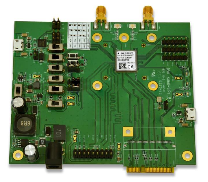
2 2. Wire the other side of rainbow cable with the connector on the DVK-ST60-SIPT/DVK-SU60-SIPT board. The pin closest to the nearby PCI-E bus should be aligned with the connector marked in red. 3. Connect the two antennas to the u.fl connectors on the DVK-ST60- SIPT/DVK-SU60-SIPT board. The development board can be powered from a DC 12V supply (into DC jack connector CN1), USB (type micro-b) connector (USB1 and USB2), or the host interface (SDIO interface). 12V DC Jack CN1 12V USB Connector USB1 / USB2 SW1 PCIe Interface SDIO Interface J3 J20 J5 SU60-SIPT Module 2

3 For regular usage, the power from SDIO bus should be enough with no need for external power from either the DC jack or USB port. To run continuous TX in a regulation test, the host may not be able to support enough current via the SDIO and may need external power. DVK-ST60-SIPT/DVK-SU60-SIPT Board Switch and Jumper Setup SDIO 2.0 supports both 1.8v and 3.3v in VIO. The following is the block diagram for the 1.8/3.3v power switching on the DVK-ST60-SIPT/DVK-SU60-SIPT board. PCIe Interface SDIO Interface J3 J20 J5 LDO 1.8V SU60-SIPT 1.8V VIO J1 REG_VIO SW2 SW4 VIO_SD J2 REG_VIO_SD SW3 3

4 The following is the layout of switches and jumpers on the DVK-ST60-SIPT/DVK-SU60-SIPT board. 4
 J10: Right (located near SIP) J9: Right (located near SIP) Switch 4: Right (located near SIP) Switch")
5 A VIO 3.3v host platform requires the following switch and jumper settings: J11: Left (located near USB2) J10: Right (located near SIP) J9: Right (located near SIP) Switch 4: Right (located near SIP) Switch 2: Left (located near USB2) Switch 3: Left (located near USB2) A VIO 1.8v host platform requires the following switch and jumper settings: J11: Left (located near USB2) J10: Right (located near SIP) J9: Left (located near USB2) Switch 4: Right (located near SIP) Switch 2: Right (located near SIP) Switch 3: Right (located near SIP) There are several Wi-Fi/BT interface support options on the DVK-ST60-SIPT/DVK-SU60-SIPT board. Table 1: Wi-Fi/BT interface support options for SDIO 2 Wi-Fi BT Switch 7 Switch 6 Switch 5 SDIO UART Left (located near USB2) Left (located near USB2) Left (located near USB2) SDIO SDIO Left (located near USB2) Left (located near USB2) Right (located near SIP) PCIe USB Left (located near USB2) Right (located near SIP) Left (located near USB2) PCIe UART Left (located near USB2) Right (located near SIP) Right (located near SIP) 5


6 ENVIRONMENT SETUP WITH SDIO 3.0 HOST DVK-ST60-SIPT/DVK-SU60-SIPT Wiring With an SDIO 3.0 host, the Laird module runs in SDR104 mode. An SDIO clock is much faster than SDIO 2.0 and it is more sensitive with a bus signal. To wire the DVK-ST60-SIPT/DVK-SU60-SIPT with SDIO 3.0 host, follow these steps to prevent a driver loading failure due to a poor SDIO signal: 1. Mount the SDIO extender board without pin header on the DVK-ST60-SIPT/DVK-SU60-SIPT SDIO connector. Align the pin closest to the PCI-E bus with the SD_D1 pin of SDIO extender board 2. Solder each pin of the SDIO extender board. 6
, USB (type micro-b) connector (USB1 and USB2), or the host interface (SDIO")

7 3. Connect the two antennas to the u.fl connectors on the DVK-ST60- SIPT/DVK-SU60-SIPT board. The development board can be powered from DC 12V supply (into DC jack connector CN1), USB (type micro-b) connector (USB1 and USB2), or the host interface (SDIO interface). 12V DC Jack CN1 12V USB Connector USB1 / USB2 SW1 PCIe Interface SDIO Interface J3 J20 J5 SU60-SIPT Module For regular usage, the power from SDIO bus should be enough with no need for external power from either the DC jack or USB port. To run continuous TX in a regulation test, the host may not be able to support enough current via the SDIO and may need external power. 7
 J10: Right (located near SIP) J9: Left (located near USB2) Switch 4: Right (located near SIP) Switch 2: Right")
8 DVK-ST60-SIPT/DVK-SU60-SIPT Board Switch and Jumper Setup SDIO 3.0 bus only supports VIO 1.8v and requires the following switch and jumper settings: J11: Left (located near USB2) J10: Right (located near SIP) J9: Left (located near USB2) Switch 4: Right (located near SIP) Switch 2: Right (located near SIP) Switch 3: Right (located near SIP) There are several options of Wi-Fi/BT interface support in DVK-ST60-SIPT/DVK-SU60-SIPT board. Table 2: Wi-Fi/BT interface support options for SDIO 3 Wi-Fi BT Switch 7 Switch 6 Switch 5 SDIO UART Left (located near USB2) Left (located near USB2) Left (located near USB2) SDIO SDIO Left (located near USB2) Left (located near USB2) Right (located near SIP) PCIe USB Left (located near USB2) Right (located near SIP) Left (located near USB2) PCIe UART Left (located near USB2) Right (located near SIP) Right (located near SIP) REVISION HISTORY Version Date Notes Approver Sept 2017 Initial release Jay White Sept 2017 Updated Table 1 and 2 Reversed the Switch 5 and Switch 7 column headins Miles Chung 8
User Guide SU60-SIPT Development Kit (DVK-SU60-SIPT) Version 1.0
 Version 1.0") A SU60-SIPT Development Kit (DVK-SU60-SIPT) Version 1.0 REVISION HISTORY Version Date Notes Approver 1.0 29 July 2017 Initial Release Jay White 2 CONTENTS 1 Overview...4 Introduction...4 Package Contents...4
A SU60-SIPT Development Kit (DVK-SU60-SIPT) Version 1.0 REVISION HISTORY Version Date Notes Approver 1.0 29 July 2017 Initial Release Jay White 2 CONTENTS 1 Overview...4 Introduction...4 Package Contents...4
User Guide M.2 Development Kit (DVK-SU C) Version 1.0
 Version 1.0") A M.2 Development Kit (DVK-SU60-2230C) Version 1.0 REVISION HISTORY Version Date Notes Approver 1.0 29 July 2017 Initial Release Jay White 2 CONTENTS 1. Overview...4 1.1 Introduction...4 1.2 Package Contents...4
A M.2 Development Kit (DVK-SU60-2230C) Version 1.0 REVISION HISTORY Version Date Notes Approver 1.0 29 July 2017 Initial Release Jay White 2 CONTENTS 1. Overview...4 1.1 Introduction...4 1.2 Package Contents...4
Official Publication Date: 12/18/2018 Official Expiration Date: Until Next Release
 Official Publication Date: 12/18/2018 Official Expiration Date: Until Next Release Revision History Version Date Comments 100 12/06/2016 Initial Release 111 6/20/2017 Updated Formatting 112 5/24/2018 Added

Datasheet BT85x Series Development Kits
 A BT85x Series Development Kits Applicable to the following Laird part numbers: DVK-BT850-SA DVK-BT850-ST Version 1.0 REVISION HISTORY Version Date Notes Contributor Approver 1.0 12 Jan 2018 Initial Release
PremierWave 2050 Enterprise Wi-Fi IoT Module Evaluation Kit User Guide
 PremierWave 2050 Enterprise Wi-Fi IoT Module Evaluation Kit User Guide Part Number 900-765-R Revision A February 2016 Intellectual Property 2016 Lantronix, Inc. All rights reserved. No part of the contents
EVALUATION BOARD MANUAL EBSHSN Series. EVALUATION KIT MANUAL EKSHSN Series
 . EVALUATION BOARD MANUAL EBSHSN Series EVALUATION KIT MANUAL EKSHSN Series for EYSHSN Series Bluetooth R low energy Module 1/7 . Introduction This evaluation board is applicable for Taiyo Yuden s Bluetooth
EVALUATION BOARD MANUAL EBSHJN Series. EVALUATION KIT MANUAL EKSHJN Series
 EVALUATION BOARD MANUAL EBSHJN Series EVALUATION KIT MANUAL EKSHJN Series for EYSHJN series Bluetooth R low energy Module 1/7 Introduction This evaluation board is applicable for Taiyo Yuden s Bluetooth
xpico Wi-Fi Embedded Device Server Evaluation Kit User Guide
 xpico Wi-Fi Embedded Device Server Evaluation Kit User Guide Part Number 900-643-R Revision B July 2013 Copyright and Trademark Warranty Contacts 2013 Lantronix, Inc. All rights reserved. No part of the
Datasheet BT860 Development Kit
 A BT860 Development Kit Applicable to the following Laird part numbers: - DVK-BT860-SA Integrated antenna version - DVK-BT860-ST Trace pin for external antenna version Version 1.0 REVISION HISTORY Version
EVALUATION BOARD MANUAL EBSLSN Series. EVALUATION KIT MANUAL EKSLSN Series
 EVALUATION BOARD MANUAL EBSLSN Series EVALUATION KIT MANUAL EKSLSN Series for EYSLSN Series Bluetooth R low energy Module 1/8 Introduction This evaluation board is applicable for Taiyo Yuden s Bluetooth
Evaluation kits for JODY-W1 host-based multiradio modules
 EVK-JODY-W1 Evaluation kits for JODY-W1 host-based multiradio modules User Guide Abstract This document describes how to set up the EVK-JODY-W1 evaluation kits to evaluate JODY-W1 series multiradio (Wi-Fi
xpico 200 Series Evaluation Kit User Guide
 xpico 200 Series Evaluation Kit User Guide This guide describes how to setup the xpico 200 series evaluation kit and provides the information needed to evaluate the included xpico 240 or xpico 250 embedded
Get Started SUPPORT WARRANTY. Visit the i.mx community at
 SUPPORT Visit the i.mx community at www.imxcommunity.org. WARRANTY Visit www.nxp.com/warranty for complete warranty information. Get Started Download installation software and documentation under Getting
The Information contained herein is subject to change without notice. Revisions may be issued regarding changes and/or additions.
 Pepper 43R TM Gumstix, Inc. shall have no liability of any kind, express or implied, arising out of the use of the Information in this document, including direct, indirect, special or consequential damages.
Toradex Colibri Development Board
 Toradex Colibri Development Board TM Gumstix, Inc. shall have no liability of any kind, express or implied, arising out of the use of the Information in this document, including direct, indirect, special
SABRE Board for Smart Devices
 Quick Start Guide SABRE Board for Smart Devices Based on the i.mx 6SoloX Applications Processor FREEDOM DEVELOPMENT PLATFORM Quick Start Guide ABOUT THE SABRE BOARD FOR SMART DEVICES BASED ON THE I.MX
Description. Overview. Features S90-MTM-DEV-2. MTM Development Board 2.0 Datasheet
 Overview The Acroname Development Board 2.0 (-DEV-2), part of Acroname s (Manufacturing Test Module) product series, is a connectivity solution designed for development or integration to wire-based testers.
Laird Regulatory Utility Guide for Windows. Version 1.0
 A Laird Regulatory Utility Guide for Windows Version 1.0 REVISION HISTORY Version Date Notes Approver 1.0 14 Sept 2015 Initial Release: Combined guide for PC and Mobile Jonathan Kaye versions of Windows.
Wi125 Evaluation Kit User Manual
 Wi125 Evaluation Kit User Manual Issue: R01 Available at Digi-Key www.digikey.com Bulletin SG172-DKUM Revision R01 Date 06 May 2010 Table of Contents 1. Introduction 3 2. Wi125 Evaluation Board Overview
TWR-PIM-41WVGA Product Brief
 Release: May 2 nd 2012 Table of content 1 GENERAL DESCRIPTION... 3 1.1 FEATURES OF TWR-PIM... 3 1.2 MAIN COMPONENTS USED IN THE DESIGN... 3 2 DESCRIPTION OF THE DESIGN... 4 2.1 TWR-PIM... 4 2.2 SLABS(SMALL
CF Plug-In. Evaluation Board User Guide. Bulletin Revision Date
 CF Plug-In Evaluation Board User Guide Bulletin Revision Date JA03-EBUG 00 06 Dec 2017 Table of Contents I. Introduction------------------------------------------------------------------------- 2 Scope
VP101-BT Installation Guide
 VP101-BT Installation Guide Package Contents 1 VP101-BT system unit 6 Mounting screws for Mini PCIe module 1 Quick Installation Guide 1 Disk includes: - Drivers / Manual Note: The CD that came with the
FPD-Link III Serialize board (NV012-A) Hardware specifications. The 1st edition. Net Vision Co., Ltd.
 Hardware specifications. The 1st edition. Net Vision Co., Ltd.") FPD-Link III Serialize board (NV012-A) Hardware specifications The 1st edition Net Vision Co., Ltd. Revision history Version Date Content Charge 1 st edit. 2015/10/08 First edition creation H.Yamada 2
FPD-Link III Serialize board (NV012-A) Hardware specifications The 1st edition Net Vision Co., Ltd. Revision history Version Date Content Charge 1 st edit. 2015/10/08 First edition creation H.Yamada 2
KDS Channel DMX Controlled Servo Kit
 KDS00801 8-Channel DMX Controlled Servo Kit This is a DMX512-A controlled servo kit using ANSI approved RJ-45 connectors for DMX networks. Power requirements are 8-20 VDC @ 50 ma. The board features an
xpico 110 Wired Device Server Module Evaluation Kit User Guide
 xpico 110 Wired Device Server Module Evaluation Kit User Guide Part Number 900-788-R Revision A April 2017 Intellectual Property 2017 Lantronix, Inc. All rights reserved. No part of the contents of this
EVALUATION BOARD MANUAL EBSGCN Series. EVALUATION KIT MANUAL EKSGCN Series
 EVALUATION BOARD MANUAL EBSGCN Series EVALUATION KIT MANUAL EKSGCN Series for EYSGCN series Bluetooth R low energy Module 1/9 Introduction This evaluation board is applicable for Taiyo Yuden s Bluetooth
Evaluate: MAX14589E/MAX14594E/ MAX MAX14589E/MAX14594E/ MAX14689 Evaluation Kits. Features and Benefits. General Description.
 Evaluation Kits General Description The MAX14589E/MAX14594E/ evaluation kits (EV kits) are fully assembled and tested circuit boards that demonstrate the functionality of the MAX14589E, MAX14594E, and
Quick Start Guide Multisensory Enablement Kit i.mx 8QuadXPlus MEK CPU Board. Based on i.mx 8QuadXPlus Applications Processor
 Quick Start Guide Multisensory Enablement Kit i.mx 8QuadXPlus MEK CPU Board Based on i.mx 8QuadXPlus Applications Processor Quick Start Guide GET TO KNOW THE MEK BASED ON i.mx 8QUADXPLUS APPLICATIONS PROCESSOR
VLSI AppNote: VSx053 Simple DSP Board
 : VSx053 Simple DSP Board Description This document describes the VS1053 / VS8053 Simple DPS Board and the VSx053 Simple DSP Host Board. Schematics, layouts and pinouts of both cards are included. The
RC1170-RC232 USER MANUAL
 RC1170-RC232 USER MANUAL Overview: Introducing RC11XX-RC232 RF Transceiver boards for the data transmission using RF. Where RC11xx transceiver modules are compact surface-mounted high performance modules
The Information contained herein is subject to change without notice. Revisions may be issued regarding changes and/or additions.
 Cobalt MC Gumstix, Inc. shall have no liability of any kind, express or implied, arising out of the use of the Information in this document, including direct, indirect, special or consequential damages.
The Information contained herein is subject to change without notice. Revisions may be issued regarding changes and/or additions.
 Pepper DVI TM Gumstix, Inc. shall have no liability of any kind, express or implied, arising out of the use of the Information in this document, including direct, indirect, special or consequential damages.
LM53X Development and Evaluation Product Family
 Development and Evaluation Family Revised Datasheet Version 13/MAR/2018 1.0 Overview The is the development and evaluation product family for the LM930 / LM931 Bluetooth low energy module. A great starting
The bridge insures that multiple PCIBPMC cards can be installed onto the same PCI bus stub.
 DE Store Home Company Search Design MadeInUSA White Papers PCIBPMC now "ET" extended temperature standard PCI to PMC Adapter / Carrier PCIBPMC Bridge based PCI and PMC Compatible Adapter Carrier Front
The Information contained herein is subject to change without notice. Revisions may be issued regarding changes and/or additions.
 Poblano 43C TM Gumstix, Inc. shall have no liability of any kind, express or implied, arising out of the use of the Information in this document, including direct, indirect, special or consequential damages.
VC230-BT Installation Guide
 VC230-BT Installation Guide Package Contents VC230-BT system unit 6 Mounting screws for Mini PCIe module Quick Installation Guide Disk includes: - Drivers / Manual The CD that came with the system contains
HiLo V2 Interface Board User Guide
 HiLo V2 Interface Board User Guide Table of Content 1. Revision History 2. Function description of all key components 3. More detail description External document URD1 OTL 5635.2 011 72396 ed 01 25 January
Raspberry Pi Compute Development board
 Raspberry Pi Compute Development board TM Gumstix, Inc. shall have no liability of any kind, express or implied, arising out of the use of the Information in this document, including direct, indirect,
A3-TFFCBL-02 USB-to-UART Adapter User Manual
 A3-TFFCBL-02 USB-to-UART Adapter User Manual Introduction The A3-TFFCBL-02 provides a convenient method for adapting UART data to USB signaling; it provides the following features: Converts from USB to
Skywire BeagleBone Black Cape Data Sheet
 Skywire BeagleBone Black Cape Data Sheet NimbeLink Corp Updated: January 2018 PN 30122 rev 2 NimbeLink Corp. 2016. All rights reserved. 1 Table of Contents Table of Contents 2 Introduction 3 Overview 3
MAX96706 GMSL Deserializer Board GMI (Board model number NV013-B) Hardware Specification. Rev. 1.0
 Hardware Specification. Rev. 1.0") MAX96706 GMSL Deserializer Board GMI-96706 (Board model number NV013-B) Hardware Specification Rev. NetVision Co., Ltd. Update History Revision Date Note 2018/04/24 New file (Equivalent to Japanese version
MAX96706 GMSL Deserializer Board GMI-96706 (Board model number NV013-B) Hardware Specification Rev. NetVision Co., Ltd. Update History Revision Date Note 2018/04/24 New file (Equivalent to Japanese version
96Boards UART Adapter User Guide
 96Boards UART Adapter User Guide For versions v1.0 and v1.1 of the UART adapter board Introduction This is the user guide for the 96Boards UART adapter board. The board provides a USB to UART adapter to
EVALUATION BOARD MANUAL EBSGJN Series EBAGJN Series. EVALUATION KIT MANUAL EKSGJN Series EKAGJN Series
 EVALUATION BOARD MANUAL EBSGJN Series EBAGJN Series EVALUATION KIT MANUAL EKSGJN Series EKAGJN Series for EYSGJN, EYAGJN series Bluetooth R low energy Module 1/9 Introduction This evaluation board is applicable
RN-WIFLY-EVAL-UM. WiFly Evaluation Kit Roving Networks. All rights reserved. RN-WIFLY-EVAL-UM-1.0 Version /8/2011 USER MANUAL
 RN-WIFLY-EVAL-UM WiFly Evaluation Kit 0 Roving Networks. All rights reserved. RN-WIFLY-EVAL-UM-.0 Version.0 //0 USER MANUAL OVERVIEW This document describes the hardware and software setup for Roving Networks
EVK-NINA-W13. Evaluation Kit for NINA-W13 modules. User Guide. Abstract
 EVK-NINA-W13 Evaluation Kit for NINA-W13 modules User Guide Abstract This document describes how to set up the EVK-NINA-W13x evaluation kits to evaluate NINA-W13 series stand-alone Wi-Fi modules. It also
SABRE for Automotive Infotainment Quick Start Guide. Smart Application Blueprint for Rapid Engineering Based on the i.mx 6 Series
 SABRE for Automotive Infotainment Quick Start Guide Smart Application Blueprint for Rapid Engineering Based on the i.mx 6 Series About SABRE Platform for Automotive Infotainment Based on the the i.mx 6
Product Change Notification PCN#
 Product Change Notification PCN# 000120171205 - PCN for MACCHIATObin which will be transitioning from: Revision 1.2 to Revision 1.3 Date of publication: December 5 th 2017 Table of Contents Background...
Intel Joule Module Platform Mechanical INTERFACE descriptor. Document Revision 1.0 August 2016
 Intel Joule Module Platform Mechanical INTERFACE descriptor Document 568978 Revision 1.0 August 2016 Contents: 1. General Overview 2. Module Mechanical Definition 3. Expansion Board Mechanical Definition
LinkIt ONE. Introduction. Specifications
 LinkIt ONE Introduction The LinkIt ONE development board is an open source, high performance board for prototyping Wearables and IoT devices. It's based on the world s leading SoC for Wearables, MediaTek
Hardware Manual - SM2251 Evaluation Kit Board
 Hardware Manual - SM2251 Evaluation Kit Board Release 1.0.0 SonMicro Elektronik Oct 08, 2017 CONTENTS 1 INTRODUCTION 1 1.1 FEATURES............................................... 1 1.2 SUPPORTED MODULES.......................................
Enabling IoT with OSD335x using Wi-Fi and Bluetooth Rev.1 3/07/18
 1 Introduction Wi-Fi is a set of wireless communication technologies developed in the 1990s and 2000s that enables millions of devices to be connected together wirelessly. This has enabled the Internet-of-Things
Intelligent Devices IDI 1100 Series Technical Manual
 Intelligent Devices IDI 1100 Series 4411 Suwanee Dam Road, Suite 510 Suwanee, GA 30024 T: (770) 831-3370 support@intelligentdevicesinc.com Copyright 2011, Intelligent Devices, Inc. All Rights Reserved
EVDK Based Speed Sign Detection Demonstration User Guide
 EVDK Based Speed Sign Detection Demonstration FPGA-UG-02049 Version 1.1 September 2018 Contents Acronyms in This Document... 4 1. Introduction... 5 2. Functional Description... 6 3. Demo Setup... 8 3.1.
Quick Start Guide WB50NBT. Version 1.1
 A WB50NBT Version 1.1 REVISION HISTORY Version Date Notes Approver 1.0 04 April 2016 Initial Version Andrew Dobbing 1.1 01 May 2017 OS Support Jay White 2 CONTENTS Revision History...2 Contents...3 Introduction
Wireless LAN Module. IEEE802.11b/g/n WYSAGVDX7
 Wireless LAN Module IEEE802.11b/g/n WYSAGVDX7 Application Note In case you adopt this module and design some appliance, please ask for the latest specifications to the local sales office. 1/12 Table of
ISMART Inventek Systems Module Arduino Test. Product Brief
 ISMART Inventek Systems Module Arduino Test Product Brief Wi-Fi, BT/BLE & NFC IoT Arduino Shields Page 1 1 General Description The Inventek ISMART (Inventek Systems Module Arduino Test) IoT platform is
C8051F36x-DK. C8051F36x DEVELOPMENT KIT USER S GUIDE. 1. Relevant Devices. 2. Kit Contents. 3. Hardware Setup Using a USB Debug Adapter
 C8051F36x DEVELOPMENT KIT USER S GUIDE 1. Relevant Devices The C8051F360 Development Kit is intended as a development platform for the microcontrollers in the C8051F36x MCU family. Notes: The target board
BS2p40tm OEM Module. Surface mount/through hole kit By Robert L. Doerr. Manual Revision.5
 BS2p40tm OEM Module Surface mount/through hole kit 2006 By Robert L. Doerr Manual Revision.5 NOTE: The BASIC Stamp and the BS2p40 and Interpreter chip are trademarks of Parallax. This partial kit allows
solutions for teaching and learning
 RKP18Motor Component List and Instructions PCB layout Constructed PCB Schematic Diagram RKP18Motor Project PCB Page 1 Description The RKP18Motor project PCB has been designed to use PIC microcontrollers
Universal RFID Socket board with RS232 / USB interface
 Data Sheet UNI_RS232_USB.pdf 9 Pages Last Revised 03/09/09 Universal RFID Socket board with RS232 / USB interface The Universal RFID Socket board is the baseboard for the MicroRWD RFID reader modules from
KDR00101 DMX Controlled Relay Kit
 KDR00101 DMX Controlled Relay Kit This is a DMX512-A relay kit using ANSI approved RJ-45 connectors for DMX networks. Power requirements are 12 Vdc @ 100 ma. The relay contact rating is 10 Amp @ 120 or
WB40NBT Quick Start Guide Version 2.0
 WB40NBT Quick Start Guide Version 2.0 Americas : +1-800-492-2320 Europe : +44-1628-858-940 Hong Kong : +852-2923-0610 REVISION HISTORY Revision Date Description Approved By 1.0 21 March 2012 Initial version
HX2VL Development Kit Guide. Doc. # Rev. *A
 HX2VL Development Kit Guide Doc. # 001-73960 Rev. *A Cypress Semiconductor 198 Champion Court San Jose, CA 95134-1709 Phone (USA): 800.858.1810 Phone (Intnl): 408.943.2600 http://www.cypress.com Copyrights
BT740 Development Kit Quick Start Guide v1.2
 v1.2 This applies to the following part numbers: DVK-BT740-SA DVK-BT740-SC INTRODUCTION There are two hardware variants (on board antenna and ufl connector for external) of the BT740 Enhanced Data Module
A-307. Mobile Data Terminal. Android OS Platform Datasheet
 A-307 Mobile Data Terminal Android OS Platform Datasheet Revision 1.2 March, 2014 A-307 Platform Overview A-307 Platform Overview The A-307 provides Original Equipment Manufacturers (OEMs) and Telematics
BC-USB-Kit Manual. First Edition. February, BeatCraft, Inc.
 BC-USB-Kit Manual First Edition February, 2015 BeatCraft, Inc. 1. Overview BC-USB-Kit is a USB-gadget development kit, which is equipped with a micro controller of Microchip Technology Inc, PIC24FJ128GB202
Intel Do-It-Yourself Challenge Intel Galileo and Edison Paul Guermonprez
 Intel Do-It-Yourself Challenge Intel Galileo and Edison Paul Guermonprez www.intel-software-academic-program.com paul.guermonprez@intel.com Intel Software 2014-02-01 Intel Galileo? Arduino? You may know
WPEQ-261ACN (BT) is a single-die wireless local area network (WLAN) and Bluetooth combo solution to support
 is a single-die wireless local area network (WLAN) and Bluetooth combo solution to support") 802.11ac/abgn Dual-Band 2T2R Wi-Fi+Bluetooth 4.1 Combo Half Mini PCIe Module Wi-Fi+Bluetooth Combo Solution Half PCIe Module WPEQ-261ACN (BT) is a single-die wireless local area network (WLAN) and Bluetooth
802.11ac/abgn Dual-Band 2T2R Wi-Fi+Bluetooth 4.1 Combo Half Mini PCIe Module Wi-Fi+Bluetooth Combo Solution Half PCIe Module WPEQ-261ACN (BT) is a single-die wireless local area network (WLAN) and Bluetooth
RN-174. WiSnap M2 Super Module. Features. Description. Applications. ~ page 1 ~ rn-174-ds v1.1 6/1/2011
 WiSnap M2 Super Module Features Development board containing the RN-171 module, status LEDs, power regulator Supports chip antenna (RN-174-C), PCB Trace antenna (RN-174-P), wire antenna (RN- 174-W) and
Using the BT85x Series with Linux and Windows Relevant to Laird # BT850-SA, BT850-ST, BT851, and associated DVKs
 A Using the BT85x Series with Linux and Windows Relevant to Laird # BT850-SA, BT850-ST, BT851, and associated DVKs v1.0 INTRODUCTION The BT85x Series are Laird s latest generation of USB HCI Dual Mode
KDR00301 DMX Controlled Relay Kit
 KDR00301 DMX Controlled Relay Kit This is a DMX512-A relay kit using ANSI approved RJ-45 connectors for DMX networks. Power requirements are 12 Vdc @ 200 ma. The relay contact rating is 10 Amp @ 120 or
VENUS_ Driving Board and 39.6 Prism Display
 VENUS_ Driving Board and 39.6 Prism Display Table of Contents 1 Hardware Requirements... 1 (1) PACKAGE CONTENTS... 1 (2) VENUS Specification... 2 (3) Prism product Specification... 3 2 Hardware Guide...
Skywire Raspberry Pi Adapter Data Sheet
 Skywire Raspberry Pi Adapter Data Sheet NimbeLink Corp Updated: October 2017 PN 1001465 rev 1 NimbeLink Corp. 2017. All rights reserved. 1 Table of Contents Table of Contents 2 Introduction 3 Overview
View Wall Interface. Dynamic Glass INSTALLATION GUIDE. Description. System Requirements. Installation Overview
 Description The solution is a compact, wall-mounted interface used for monitoring and changing the tint levels of View Dynamic Glass. The product leverages 802.11-based Wi-Fi technology for connectivity
MIRAGE Sierra mangoh TM IoT WiFi + Bluetooth + NFC Datasheet
 FEATURES WiFi 802.11 a/b/g/n 20 and 40MHz SISO Bluetooth Classic 2.1 Bluetooth Smart 4.1 NFC Forum type 2 Tag NFC Field Detect Wakeup Digital PCM Audio + SBC and A2DP Integrated high performance trace
UM User Manual for LPC54018 IoT Module. Rev November Document information
 UM11078 for Rev. 1.01 27 November 2017 Document information Info Content Keywords LPC54018, OM40007, GT1216, UM11078 Abstract Revision history Rev Date Description 1.0 20171122 First draft 1.01 20171127
4.0 Blue LED DCF77 Clock documentation
 4.0 Blue LED DCF77 Clock documentation 1. LED Clock Main Board PCB mounting: Mount and solder the eight wire bridges. Mount and solder resistors R16, R18, R20, R22. Mount and solder capacitors C1 C3 (pitch
SAMSUNG ELECTRONICS RESERVES THE RIGHT TO CHANGE PRODUCTS, INFORMATION AND SPECIFICATIONS WITHOUT NOTICE. Products and specifications discussed
 SAMSUNG ELECTRONICS RESERVES THE RIGHT TO CHANGE PRODUCTS, INFORMATION AND SPECIFICATIONS WITHOUT NOTICE. Products and specifications discussed herein are for reference purposes only. All information discussed
AVR Intermediate Development Board. Product Manual. Contents. 1) Overview 2) Features 3) Using the board 4) Troubleshooting and getting help
 Overview 2) Features 3) Using the board 4) Troubleshooting and getting help") AVR Intermediate Development Board Product Manual Contents 1) Overview 2) Features 3) Using the board 4) Troubleshooting and getting help 1. Overview 2. Features The board is built on a high quality FR-4(1.6
AVR Intermediate Development Board Product Manual Contents 1) Overview 2) Features 3) Using the board 4) Troubleshooting and getting help 1. Overview 2. Features The board is built on a high quality FR-4(1.6
CBL Starter Cable Kit for DuraNAV System
 Technical Datasheet Td0008 CBL-1010-00 Starter Cable Kit for DuraNAV System Overview The CBL-1010-00 Cable Kit is designed to allow users of the DuraNAV to rapidly start developing and testing software,
EX & EX-45362IS 2S RS232/422/485 3-in-1 Serial PCIe Card
 EX-45362 & EX-45362IS 2S RS232/422/485 3-in-1 Serial PCIe Card Congratulation on your purchasing this high performance 2-Port RS232/422/485 3-in-1 Serial PCIe Host Adapter. The adapter is high speed PCIe
Raspberry Pi board. EB080
 Raspberry Pi board www.matrixmultimedia.com EB080 Contents About this document 3 Board layout 3 General information 4 Circuit description 4 Circuit diagram 5 2 Copyright Matrix Multimedia Ltd. About this
Lesson 6 Intel Galileo and Edison Prototype Development Platforms. Chapter-8 L06: "Internet of Things ", Raj Kamal, Publs.: McGraw-Hill Education
 Lesson 6 Intel Galileo and Edison Prototype Development Platforms 1 Intel Galileo Gen 2 Boards Based on the Intel Pentium architecture Includes features of single threaded, single core and 400 MHz constant
Ci40. Hardware User Guide
 Public Imagination Technologies Ci40 Hardware User Guide Copyright Imagination Technologies Limited. All Rights Reserved. We make no warranty, representation, or guarantee regarding the information contained
RFID: Read and Display V2010. Version 1.1. Sept Cytron Technologies Sdn. Bhd.
 PR8-B RFID: Read and Display V2010 Version 1.1 Sept 2010 Cytron Technologies Sdn. Bhd. Information contained in this publication regarding device applications and the like is intended through suggestion
Interposers, Probes and Adapters for LeCroy PCI Express Systems
 Protocol Solutions Group Product Datasheet, Probes and Adapters for LeCroy PCI Express s A Wide Variety of Bus Probing Options MidBus Probe The LeCroy PCI Express Product Line includes a wide variety of
KNJN I2C bus development boards
 KNJN I2C bus development boards 2005, 2006, 2007, 2008 KNJN LLC http://www.knjn.com/ Document last revision on December 5, 2008 R22 KNJN I2C bus development boards Page 1 Table of Contents 1 The I2C bus...4
Quick Start Guide Sentrius RG1xx. Version 2.1
 A Version 2.1 REVISION HISTORY Version Date Notes Approver 1.0 20 July 2017 Initial Release Jonathan Kaye 1.1 28 July 2017 Minor fixes Dave Drogowski 1.2 3 Aug 2017 Clarified web interface URL in section
UC-8410A Quick Installation Guide
 UC-8410A Quick Installation Guide Edition 1.0, May 2016 Technical Support Contact Information www.moxa.com/support Moxa Americas: Toll-free: 1-888-669-2872 Tel: 1-714-528-6777 Fax: 1-714-528-6778 Moxa
Soartronic IOIO UART interface v2e assembly manual.
 Soartronic IOIO UART interface v2e assembly manual www.soartronic.com 1 This manual is for both IOIO v1 and IOIO-OTG Components assembled should look like this: components marked with RED arrows have polarity,
LPC1788 Mio Board. The functional details of the board are as follows-
 INTRODUCTION : The LPC1788 Mio is based on Cortex M3 Core, running at up to 120MHz. The Mio lets you quickly start with your development on LPC1788 based designs. The functional details of the board are
Quick Start Guide. SABRE Platform for Smart Devices Based on the i.mx 6 Series
 Quick Start Guide SABRE Platform for Smart Devices Based on the i.mx 6 Series Quick Start Guide About the SABRE Platform for Smart Devices Based on the i.mx 6 Series The Smart Application Blueprint for
ZeptoBit Isolated USB-UART Adapter Datasheet
 Table of Contents Summary...1 Main features...1 Driver...2 Electrical characteristics...2 Absolute maximum ratings...2 Operating conditions...2 Pinout...3 Mechanical...3 Principles of operation...3 USB-UART
EVK-NINA-W10. Evaluation Kit for NINA-W10 modules. User Guide. Abstract
 EVK-NINA-W10 Evaluation Kit for NINA-W10 modules User Guide Abstract This document describes how to set up the EVK-NINA-W10x evaluation kits to evaluate NINA-W10 series stand-alone multiradio (2.4 GHz
Features C U. 1 x AIM dock 16-pin pogo connector: 1 x USB 3.0, 9V power 1 x Power Buttons
 AIM-65 8" Industrial-Grade Tablet with Intel Atom Processor Intel Atom processor for Windows 10 IoT and Android 6.0 operating systems 8" WUXGA full HD display with scratch-resistant Corning Gorilla Glass
Stellaris LM3S3748 Evaluation Kit README FIRST
 Stellaris LM3S3748 Evaluation Kit README FIRST The Stellaris LM3S3748 Evaluation Kit provides a low-cost way to start designing applications with Stellaris microcontrollers on a compact and versatile evaluation
RN-174. WiFly GSX Super Module. Features. Description. Applications. rn-174-ds v1.1 3/3/2011
 www.rovingnetworks.com rn-174-ds v1.1 3/3/2011 WiFly GSX Super Module Features Development board containing the RN-171 module, status LEDs, power regulator Supports chip antenna (-C), PCB Trace antenna
RN-174. WiFly GSX Super Module. Features. Description. Applications. rn-174-ds v1.1 4/20/2011
 www.rovingnetworks.com rn-174-ds v1.1 4/20/2011 WiFly GSX Super Module Features Development board containing the RN-171 module, status LEDs, power regulator Supports chip antenna (-C), PCB Trace antenna
Version:V1.0 Date: AN0007E. Introduction. Reflow soldering when SMT
 SDIO SPI Application Note Guide for user design Version:V1.0 Date:2016-5-31 AN0007E Introduction This note lists the matters need attention in each stage of designing and manufacturing while using MXCHIP