INPUT/OUTPUT ORGANIZATION
|
|
|
- Lionel Kelley
- 6 years ago
- Views:
Transcription
1 INPUT/OUTPUT ORGANIZATION Accessing I/O Devices I/O interface Input/output mechanism Memory-mapped I/O Programmed I/O Interrupts Direct Memory Access Buses Synchronous Bus Asynchronous Bus
2 I/O in CO and O/S Programmed I/O Interrupts DMA (Direct memory Access)
3 A bus is a shared communication link, which uses one set of wires to connect multiple subsystems. The two major advantages of the bus organization are The two major advantages of the bus organization are versatility and low cost.
4 Accessing I/O Devices Most modern computers use single bus arrangement for connecting I/O devices to CPU & Memory The bus enables all the devices connected to it to exchange information Bus consists of 3 set of lines : Address, Data, Control Processor places a particular address (unique for an I/O Dev.) on address lines Device which recognizes this address responds to the commands issued on the Control lines Processor requests for either Read / Write The data will be placed on Data lines
5 Hardware to connect I/O devices to bus Interface Circuit Address Decoder Control Circuits Data registers Status registers The Registers in I/O Interface buffer and control Flags in Status Registers, like SIN, SOUT Data Registers, like Data-IN, Data-OUT
6 I/O interface for an input device Memory Processor Address Data Control Address Control Data and status t Decoders circuits registers I/O Interface Input device (s)
7 Input Output mechanism Memory mapped I/O Programmed I/O Interrupts DMA (Direct memory Access)
8 A bus generally contains a set of control lines and a set of data lines. The control lines are used to signal requests and acknowledgments, and to indicate what type of information is on the data lines. The control lines are used to indicate what the bus contains and to implement the bus protocol. The data lines of the bus carry information between the source and the destination. This information may consist of data, complex commands, or addresses. Buses are traditionally i classified as processor-memory buses or I/O buses or special purposed buses (Graphics, etc. ). Processor memory buses are short, generally high speed, and matched to the memory system so as to maximize memoryprocessor bandwidth. I/O b b t t b l th h I/O buses, by contrast, can be lengthy, can have many types of devices connected to them, and often have a wide range in the data bandwidth of the devices connected to them. I/O buses do not typically interface directly to the memory but use either a processor-memory or a backplane bus to connect to memory.
9 The major disadvantage of a bus is that it creates a communication bottleneck, possibly limiting the maximum I/O throughput. When I/O must pass through a single bus, the bandwidth of that bus limits the maximum I/O throughput. Reason why bus design is so difficult : - the maximum bus speed is largely limited by physical factors: the length of the bus and the number of devices. These physical limits prevent us from running the bus arbitrarily fast. - In addition, the need to support a range of devices with widely varying latencies and data transfer rates also makes bus design challenging. - it becomes difficult to run many parallel wires at high speed due to clock skew and reflection.
10 The two basic schemes for communication on the bus are synchronous and asynchronous. If a bus is synchronous (e.g. Processor-memory), it includes a clock in the control lines and a fixed protocol for communicating that is relative to the clock. This type of protocol can be implemented easily in a small finite state machine. Because the protocol is predetermined and involves little logic, the bus can run very fast and the interface logic will be small. Synchronous buses have two major disadvantages: - First, every device on the bus must run at the same clock rate. - Second, because of clock skew problems, synchronous buses cannot be long if they are fast. An asynchronous bus is not clocked. It can accommodate a wide variety of devices, and the bus can be lengthened without worrying about clock skew or synchronization problems. To coordinate the transmission of data between sender and receiver, an asynchronous bus uses a handshaking protocol.
11 Three special control lines required for hand-shaking: ReadReq: Used to indicate a read request for memory. The address is put on the data lines at the same time. DataRdy: Used to indicate that t the data word is now ready on the data lines; asserted by: Output/Memory and Input/I_O Device. Ack: Used to acknowledge the ReadReq or the DataRdy signal of the Ack: Used to acknowledge the ReadReq or the DataRdy signal of the other party.
12 I/O Dev. Memory Steps after the device signals a request by raising ReadReq and putting the address on the Data lines: 1. When memory sees the ReadReq line, it reads the address from the data bus and raises Ack to indicate it has been seen. 2. As the Ack line is high - I/O releases the ReadReq and data lines. 3. Memory sees that ReadReq is low and drops the Ack line to acknowledge the ReadReq signal (Mem. Reading in progress now). 4. This step starts when the memory has the data ready. It places the data from the read request on the data lines and raises DataRdy. 5. The I/O device sees DataRdy, reads the data from the bus, and signals that it has the data by raising Ack. 6. On the Ack signal, M/M drops DataRdy, and releases the data lines. 7. Finally, the I/O device, seeing DataRdy go low, drops the Ack line, which indicates that the transmission is completed.
13
14 Memory mapped I/O I/O devices and the memory share the same address space, the arrangement is called Memory-mapped I/O. In Memory-mapped I/O portions of address space are assigned to I/O devices and reads and writes to those addresses are interpreted as commands to the I/O device. DATAIN is the address of the input buffer associated with the keyboard. - Move DATAIN, R0 reads the data from DATAIN and stores them into processor register R0; - Move R0, DATAOUT sends the contents of register R0 to location DATAOUT Option of special I/O address space or incorporate as a part of memory address space (address bus is same always).
15 When the processor places the address and data on the memory bus, the memory system ignores the operation because the address indicates a portion of the memory space used for I/O. The device controller, however, sees the operation, records the data, and transmits it to the device as a command. User programs are prevented from issuing I/O operations directly because the OS does not provide access to the address space assigned to the I/O devices and thus the addresses are protected by the address translation. Memory mapped I/O can also be used to transmit data by writing or reading to select addresses. The device uses the address to determine the type of command, and the data may be provided by a write or obtained by a read. A program request usually requires several separate I/O operations. Furthermore, the processor may have to interrogate the status of the device between individual commands to determine whether the command completed successfully.
16 DATAIN DATAOUT STATUS DIRQ KIRQ SOUT SIN CONTROL DEN KEN I/O operation involving keyboard and display devices Registers: DATAIN, DATAOUT, STATUS, CONTROL Flags: SIN, SOUT - Provides status information for keyboard and display unit KIRQ, DIRQ Keyboard, Display Interrupt request bits DEN, KEN Keyboard, Display Enable bits
17 Programmed I/O CPU has direct control over I/O Sensing status t Read/write commands Transferring data CPU waits for I/O module to complete operation Wastes CPU time
18 In this case, use dedicated I/O instructions in the processor. These I/O instructions can specify both the device number and the command word (or the location of the command word in memory). The processor communicates the device address via a set of wires normally included as part of the I/O bus. The actual command can be transmitted over the data lines in the bus. (example - Intel IA-32). By making the I/O instructions illegal to execute when not in kernel or supervisor mode, user programs can be prevented from accessing the devices directly. The process of periodically checking status bits to see if it is time for the next I/O operation, is called polling. Polling is the simplest way for an I/O device to communicate with the processor. The I/O device simply puts the information in a Status register, and the processor must come and get the information. The processor is totally in control and does all the work.
19 A ISA program to read one line from the keyboard, store it in memory buffer, and echo it back to the display
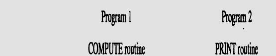
20 The disadvantage of polling is that it can waste a lot of processor time because processors are so much faster than I/O devices. The processor may read the Status register many times, only to find that the device has not yet completed a comparatively slow I/O operation, or that the mouse has not budged since the last time it was polled. When the device completes an operation, we must still read the status to determine whether it (I/O) was successful. Overhead in a polling interface lead to the invention of interrupts to notify the processor when an I/O device requires attention from the processor. Interrupt-driven I/O, employs I/O interrupts to indicate to the processor that an I/O device needs attention. When a device wants to notify the processor that it has When a device wants to notify the processor that it has completed some operation or needs attention, it causes the processor to be interrupted.
21 Interrupts I/O INTERRUPT Processor When I/O Device is ready, it sends the INTERRUPT signal to processor via a dedicated controller line Using interrupt we are ideally eliminating WAIT period In response to the interrupt, the processor executes the Interrupt Service Routine (ISR) All the registers, flags, program counter values are saved by the processor before running ISR The time required to save status & restore contribute to execution overhead Interrupt Latency

22
23 interrupt-acknowledge signal - I/O device interface accomplishes this by execution of an instruction in the interrupt-service routine (ISR) that accesses a status or data register in the device interface; implicitly informs the device that its interrupt request has been recognized. IRQ signal is then removed by device. ISR is a sub-routine may belong to a different user than the one being executed and then halted. The condition code flags and the contents of any registers used by both the interrupted program and the interrupt-service routine are saved and restored. The concept of interrupts is used in operating systems and din many control applications, i where processing of certain routines must be accurately timed relative to external events (e.g. real-time processing).
24 Interrupt Hardware Pull-up up resister INTR = INTR1 +..+INTR n An equivalent circuit for an open-drain bus used to implement a common interrupt-request line
25 Interrupt Hardware Supply Processor INTR R Pull-up resister INTR 1 INTR 2 INTR 3 INTR = INTR1 +..+INTR n GND INTR
26 Enabling and Disabling Interrupts Device activates interrupt signal line and waits with this signal activated until processors attends The interrupt signal line is active during execution of ISR and till the device caused interrupt is serviced Necessary to ensure that the active signal does not lead to successive interruptions (level-triggered input) causing the system to fall in infinite loop. What if the same device interrupts again, within an ISR? Three methods of Controlling Interrupts (single device) Ignoring interrupt Disabling interrupts Special Interrupt request line
27 Ignoring Interrupts Processor hardware ignores the interrupt request line until the execution of the first instruction of the ISR completed Using an interrupt disable instruction after the first instruction of the ISR no further interrupts A return from interrupt instruction is completed before further interruptions can occur Disabling Interrupts Processor automatically disables interrupts before starting the execution of the ISR The processor saves the contents of PC and PS (status register) before performing interrupt disabling. The interrupt-enable is set to 0 no further interrupts allowed When return from interrupt instruction is executed the contents of the PS are restored from the stack, and the interrupt enable is set to 1
28 Special Interrupt line Special interrupt request line for which the interrupt handling circuit it responds only to the leading edge of the signal Edge triggered Processor receives only one request regardless of how long the line is activated Noseparate interrupt t disabling instructions ti
29 The sequence of events involved in handling an interrupt request from a single device. Assuming that interrupts are enabled, the following is a typical scenario: 1. The device raises an interrupt request. 2. The processor interrupts the program currently being executed. 3. Interrupts are disabled by changing the control bits in the PS (except in the case of edge-triggered interrupts). 4. The device is informed that its request has been recognized, and in response, it deactivates t the interrupt- t request signal. 5. The action requested by the interrupt is performed by the interrupt-service routine. 6. Interrupts are enabled and execution of the interrupted program is resumed.
30 Handling Multiple Devices Multiple devices can initiate interrupts They uses the common interrupt request line Techniques are Polling Vectored Interrupts Interrupt Nesting Daisy Chaining
31 Polling Scheme The IRQ (interrupt request) bit in the status register is set when a device is requesting an interrupt. The Interrupt service routine polls the I/O devices connected to the bus. The first device encountered with the IRQ bit set is serviced and the subroutine is invoked. Easy to implement, but too much time spent on checking the IRQ bits of all devices, though some devices may not be requesting service.
32 Vectored Interrupts Device requesting an interrupt identifies itself directly to the processor The device sends a special code to the processor over the bus. Thecodecontainsthe identification of the device, starting address for the ISR, address of the branch to the ISR PC finds the ISR address from the code. To add flexibility for multiple devices - corresponding ISR is executed by the processor using a branch address to the appropriate routine - device specified Interrupt Vector.
33 An interrupt vector is the memory address of an interrupt handler, or an index into an array called an interrupt vector table or dispatch table - a table of interrupt vectors (pointers to routines that handle interrupts). Interrupt vector tables contain the memory addresses of interrupt handlers. When an interrupt is generated, the processor saves its execution state via a context switch, and begins execution of the interrupt t handler at the interrupt t vector. The Interrupt Descriptor Table (IDT) is specific to the I386 architecture. It tells where the Interrupt Service Routines (ISR) are located. Each interrupt number is reserved for a specific purpose. For example, 16 of the vectors are reserved for the 16 IRQ lines. On PCs, the interrupt vector table (IVT or IDT) consists of byte pointers - the first 32 (0-31 or 00-1F) of which are reserved for processor exceptions; the rest for hardware interrupts, software interrupts. This resides in the first 1 K of addressable memory.
34 Interrupt Nesting Pre-Emption of low priority Interrupt by another high priority interrupt is known as Interrupt nesting. Disabling Interrupts t during the execution of the ISR may not favor devices which need immediate attention. Need a priority of IRQ devices and accepting IRQ from a high priority device. The priority level of the processor can be changed dynamically. y The privileged instruction write in the PS (processor status word), that encodes the processors priority.
35 Interrupt Nesting (contd.) Pro ocessor INTR 1... Device 1 Device 2 Device p INTR p INTA 1 INTA p Priority arbitration circuit Organizing g I/O devices in a prioritized structure. Each of the interrupt-request lines is assigned a different priority level. The processor is interrupted only by a high priority device.
36 Daisy Chaining The interrupt request line INTR is common to all the devices The interrupt acknowledgement line INTA is connected to devices in a DAISY CHAIN way INTA propagates serially through the devices Device that is electrically closest to the processor gets highh priority i Low priority device may have a danger of STARVATION INTR Processor r P.. INTA Device 1 Device 2 Device n
37 Daisy Chaining with Priority Group Combining Daisy chaining and Interrupt nesting to form priority group Each group has different priority levels and within each group devices are connected in daisy chain way INTR1 Proc cessor INTA 1 INTR p Device 1 Device 1.. INTA p Priority arbitration circuit Device 1 Device 1 Arrangement of priority groups
38 Direct Memory Access (DMA) For I/O transfer, Processor determines the status of I/O devices, by Polling Waiting for Interrupt signal Considerable overhead is incurred in above I/O transfer processing To transfer large blocks of data at high Speed, between EXTERNAL devices & Main Memory, DMA approach is often used DMA controller allows data transfer directly between I/O device and Memory, with ih minimal i interventioni of processor.
39 Direct Memory Access (DMA) DMA controller acts as a Processor, but it is controlled by CPU To initiate transfer of a block of words, the processor sends the following data to controller The starting address of the memory block The word count Control to specify the mode of transfer such as read or write A control to start the DMA transfer DMA controller performs the requested I/O operation and sends a interrupt to the processor upon completion
40 Status and Control IRQ IE R/W Done Starting address Word count In DMA interface First register stores the starting address Second register stores Word count Third register contains status and control flags Bits and Flags 1 0 R/W READ WRITE Done IRQ IE Data transfer finishes Interrupt request Raise interrupt (enable) after Data Transfer
41 Processor Main memory Disk/DMA controller DMA controller Printer Keyboard Disk Disk Network Interface Use of DMA Controller in a computer system
42 Memory accesses by the processor and DMA Controller are interwoven DMA devices have higher priority then processor over BUS control Cycle Stealing:- DMA Controller steals memory cycles from processor, though processor originates most memory access. Block or Burst mode:- The DMA controller may given exclusive access to the main memory to transfer a block of data without interruption Conflicts in DMA: - Processor and DMA, - Two DMA controllers, try to use the Bus at the same time to access the main memory
43 DMA and Interrupt Breakpoints During an Instruction ti Cycle
44 Bus Arbitration Bus master: device that initiates data transfers on the bus. The next device can take control of the bus after the current master relinquishes control Bus Arbitration: process by which the next device to become master is selected Centralized and Distributed Arbitration
45 BBSY Processor r BG1 DMA controller 1 BR BG2 DMA controller 2 A simple arrangement for bus arbitration using a daisy chain BR (bus request ) line - open drain line - the signal on this line is a logical OR of the bus request from all the DMA devices BG (bus grant) line - processor activates this line indicating (acknowledging) to all the DMA devices (connected in daisy chain fashion) that the BUS may be used when its free. BBSY (bus busy) line - open collector line - the current bus master indicates devices that it is currently using the bus by signaling this line
46 BBSY or Process BG1 BR DMA DMA controller 1 controller 2 BG2 Sequence of signals during data transfer of bus mastership
47 Centralized Arbitration Separate unit (bus arbitration circuitry) connected to the bus Processor is normally the bus master, unless it grants bus mastership to DMA For the timing/control, in previous slide: DMA controller 2 requests and acquires bus mastership and later releases the bus. During its tenure as the bus master, it may perform one or more data transfer operations, depending on whether it is operating in the cycle stealing or block mode. After it releases the bus, the processor resumes bus After it releases the bus, the processor resumes bus mastership.
48 Distributed Arbitration All devices waiting to use the bus has to carry out the arbitration process - no central arbiter Each device on the bus is assigned with a 4-bit identification number One or more devices request the bus by asserting the start-arbitration signal and place their identification number on the four open collector lines ARB0 through ARB3 are the four open collector lines One among the four is selected using the code on the lines and one with the highest ID number
49 A distributed arbitration scheme
50 Assume that two devices, A and B, having ID numbers 5 and 6, respectively, are requesting the use of the bus. Device A transmits the pattern 0101, and device B transmits the pattern The code seen by both devices is Each device compares the pattern on the arbitration lines to its own ID, starting from the most significant bit. If it detects a difference at any bit position, it disables its drivers at that bit position and for all lower-order bits. It does so by placing a 0 at the input of these drivers. In the case of our example, device A detects a difference on line ARB I. Hence, it disables its drivers on lines ARB 1 and ARBO. This causes the pattern on the arbitration lines to change to 0110, which means that B has won the contention.
51
INPUT/OUTPUT ORGANIZATION
 INPUT/OUTPUT ORGANIZATION Accessing I/O Devices I/O interface Input/output mechanism Memory-mapped I/O Programmed I/O Interrupts Direct Memory Access Buses Synchronous Bus Asynchronous Bus I/O in CO and
INPUT/OUTPUT ORGANIZATION
 INPUT/OUTPUT ORGANIZATION Accessing I/O Devices I/O interface Input/output mechanism Memory-mapped I/O Programmed I/O Interrupts Direct Memory Access Buses Synchronous Bus Asynchronous Bus I/O in CO and
Unit 5. Memory and I/O System
 Unit 5 Memory and I/O System 1 Input/Output Organization 2 Overview Computer has ability to exchange data with other devices. Human-computer communication Computer-computer communication Computer-device
Chapter 5 Input/Output Organization. Jin-Fu Li Department of Electrical Engineering National Central University Jungli, Taiwan
 Chapter 5 Input/Output Organization Jin-Fu Li Department of Electrical Engineering National Central University Jungli, Taiwan Outline Accessing I/O Devices Interrupts Direct Memory Access Buses Interface
HANDLING MULTIPLE DEVICES
 HANDLING MULTIPLE DEVICES Let us now consider the situation where a number of devices capable of initiating interrupts are connected to the processor. Because these devices are operationally independent,
Unit 3 and Unit 4: Chapter 4 INPUT/OUTPUT ORGANIZATION
 Unit 3 and Unit 4: Chapter 4 INPUT/OUTPUT ORGANIZATION Introduction A general purpose computer should have the ability to exchange information with a wide range of devices in varying environments. Computers
UNIT V INPUT OUTPUT ORGANIZATION
 UNIT V Unit objective INPUT OUTPUT ORGANIZATION In this unit you will be introduced to : How program-controlled I/O is performed using polling, The idea of interrupts and the hardware and software needed
CS152 Computer Architecture and Engineering Lecture 20: Busses and OS s Responsibilities. Recap: IO Benchmarks and I/O Devices
 CS152 Computer Architecture and Engineering Lecture 20: ses and OS s Responsibilities April 7, 1995 Dave Patterson (patterson@cs) and Shing Kong (shing.kong@eng.sun.com) Slides available on http://http.cs.berkeley.edu/~patterson
ACCESSING I/O DEVICES
 ACCESSING I/O DEVICES A simple arrangement to connect I/O devices to a computer is to use a single bus structure. It consists of three sets of lines to carry Address Data Control Signals. When the processor
UNIT 2 MACHINE INSTRUCTIONS & PROGRAMS (CONT.)
") 1 UNIT 2 MACHINE INSTRUCTIONS & PROGRAMS (CONT.) ADDRESSING MODES The different ways in which the location of an operand is specified in an instruction are referred to as addressing modes (Table 2.1).
1 UNIT 2 MACHINE INSTRUCTIONS & PROGRAMS (CONT.) ADDRESSING MODES The different ways in which the location of an operand is specified in an instruction are referred to as addressing modes (Table 2.1).
Chapter 8. A Typical collection of I/O devices. Interrupts. Processor. Cache. Memory I/O bus. I/O controller I/O I/O. Main memory.
 Chapter 8 1 A Typical collection of I/O devices Interrupts Cache I/O bus Main memory I/O controller I/O controller I/O controller Disk Disk Graphics output Network 2 1 Interfacing s and Peripherals I/O
CMSC 313 COMPUTER ORGANIZATION & ASSEMBLY LANGUAGE PROGRAMMING LECTURE 09, SPRING 2013
 CMSC 313 COMPUTER ORGANIZATION & ASSEMBLY LANGUAGE PROGRAMMING LECTURE 09, SPRING 2013 TOPICS TODAY I/O Architectures Interrupts Exceptions FETCH EXECUTE CYCLE 1.7 The von Neumann Model This is a general
Programmed I/O Interrupt-Driven I/O Direct Memory Access (DMA) I/O Processors. 10/12/2017 Input/Output Systems and Peripheral Devices (02-2)
 I/O Processors. 10/12/2017 Input/Output Systems and Peripheral Devices (02-2)") Programmed I/O Interrupt-Driven I/O Direct Memory Access (DMA) I/O Processors 1 Principle of Interrupt-Driven I/O Multiple-Interrupt Systems Priority Interrupt Systems Parallel Priority Interrupts Daisy-Chain
Programmed I/O Interrupt-Driven I/O Direct Memory Access (DMA) I/O Processors 1 Principle of Interrupt-Driven I/O Multiple-Interrupt Systems Priority Interrupt Systems Parallel Priority Interrupts Daisy-Chain
Computer Organization ECE514. Chapter 5 Input/Output (9hrs)
") Computer Organization ECE514 Chapter 5 Input/Output (9hrs) Learning Outcomes Course Outcome (CO) - CO2 Describe the architecture and organization of computer systems Program Outcome (PO) PO1 Apply knowledge
Computer Organization ECE514 Chapter 5 Input/Output (9hrs) Learning Outcomes Course Outcome (CO) - CO2 Describe the architecture and organization of computer systems Program Outcome (PO) PO1 Apply knowledge
 Accessing I/O Devices Interface to CPU and Memory Interface to one or more peripherals Generic Model of IO Module Interface for an IO Device: CPU checks I/O module device status I/O module returns status
INPUT-OUTPUT ORGANIZATION
 INPUT-OUTPUT ORGANIZATION Peripheral Devices: The Input / output organization of computer depends upon the size of computer and the peripherals connected to it. The I/O Subsystem of the computer, provides
8. Interfacing Processors and Peripherals
 8. Interfacing Processors and Peripherals Revisions Date March 23, 2003 March 31, 2003 Changes More details on synchronous buses have been added to section 8.4 Details and more diagrams in the section
INPUT/OUTPUT DEVICES Dr. Bill Yi Santa Clara University
 INPUT/OUTPUT DEVICES Dr. Bill Yi Santa Clara University (Based on text: David A. Patterson & John L. Hennessy, Computer Organization and Design: The Hardware/Software Interface, 3 rd Ed., Morgan Kaufmann,
6 Direct Memory Access (DMA)
") 1 License: http://creativecommons.org/licenses/by-nc-nd/3.0/ 6 Direct Access (DMA) DMA technique is used to transfer large volumes of data between I/O interfaces and the memory. Example: Disk drive controllers,
1 License: http://creativecommons.org/licenses/by-nc-nd/3.0/ 6 Direct Access (DMA) DMA technique is used to transfer large volumes of data between I/O interfaces and the memory. Example: Disk drive controllers,
1. Define Peripherals. Explain I/O Bus and Interface Modules. Peripherals: Input-output device attached to the computer are also called peripherals.
 1. Define Peripherals. Explain I/O Bus and Interface Modules. Peripherals: Input-output device attached to the computer are also called peripherals. A typical communication link between the processor and
Generic Model of I/O Module Interface to CPU and Memory Interface to one or more peripherals
 William Stallings Computer Organization and Architecture 7 th Edition Chapter 7 Input/Output Input/Output Problems Wide variety of peripherals Delivering different amounts of data At different speeds In
Input/Output Problems. External Devices. Input/Output Module. I/O Steps. I/O Module Function Computer Architecture
 168 420 Computer Architecture Chapter 6 Input/Output Input/Output Problems Wide variety of peripherals Delivering different amounts of data At different speeds In different formats All slower than CPU
ECE 341. Lecture # 19
 ECE 341 Lecture # 19 Instructor: Zeshan Chishti zeshan@ece.pdx.edu December 3, 2014 Portland State University Announcements Final exam is on Monday, December 8 from 5:30 PM to 7:20 PM Similar format and
Top-Level View of Computer Organization
 Top-Level View of Computer Organization Bởi: Hoang Lan Nguyen Computer Component Contemporary computer designs are based on concepts developed by John von Neumann at the Institute for Advanced Studies
I/O - input/output. system components: CPU, memory, and bus -- now add I/O controllers and peripheral devices. CPU Cache
 I/O - input/output system components: CPU, memory, and bus -- now add I/O controllers and peripheral devices CPU Cache CPU must perform all transfers to/from simple controller, e.g., CPU reads byte from
Input Output (IO) Management
 Management") Input Output (IO) Management Prof. P.C.P. Bhatt P.C.P Bhatt OS/M5/V1/2004 1 Introduction Humans interact with machines by providing information through IO devices. Manyon-line services are availed through
Input Output (IO) Management Prof. P.C.P. Bhatt P.C.P Bhatt OS/M5/V1/2004 1 Introduction Humans interact with machines by providing information through IO devices. Manyon-line services are availed through
Interconnecting Components
 Interconnecting Components Need interconnections between CPU, memory, controllers Bus: shared communication channel Parallel set of wires for data and synchronization of data transfer Can become a bottleneck
INPUT-OUTPUT ORGANIZATION
 1 INPUT-OUTPUT ORGANIZATION Peripheral Devices Input-Output Interface Asynchronous Data Transfer Modes of Transfer Priority Interrupt Direct Memory Access Input-Output Processor Serial Communication 2
EE108B Lecture 17 I/O Buses and Interfacing to CPU. Christos Kozyrakis Stanford University
 EE108B Lecture 17 I/O Buses and Interfacing to CPU Christos Kozyrakis Stanford University http://eeclass.stanford.edu/ee108b 1 Announcements Remaining deliverables PA2.2. today HW4 on 3/13 Lab4 on 3/19
The control of I/O devices is a major concern for OS designers
 Lecture Overview I/O devices I/O hardware Interrupts Direct memory access Device dimensions Device drivers Kernel I/O subsystem Operating Systems - June 26, 2001 I/O Device Issues The control of I/O devices
Systems Architecture II
 Systems Architecture II Topics Interfacing I/O Devices to Memory, Processor, and Operating System * Memory-mapped IO and Interrupts in SPIM** *This lecture was derived from material in the text (Chapter
Lecture 13. Storage, Network and Other Peripherals
 Lecture 13 Storage, Network and Other Peripherals 1 I/O Systems Processor interrupts Cache Processor & I/O Communication Memory - I/O Bus Main Memory I/O Controller I/O Controller I/O Controller Disk Disk
PC Interrupt Structure and 8259 DMA Controllers
 ELEC 379 : DESIGN OF DIGITAL AND MICROCOMPUTER SYSTEMS 1998/99 WINTER SESSION, TERM 2 PC Interrupt Structure and 8259 DMA Controllers This lecture covers the use of interrupts and the vectored interrupt
ECE468 Computer Organization and Architecture. OS s Responsibilities
 ECE468 Computer Organization and Architecture OS s Responsibilities ECE4680 buses.1 April 5, 2003 Recap: Summary of Bus Options: Option High performance Low cost Bus width Separate address Multiplex address
操作系统概念 13. I/O Systems
 OPERATING SYSTEM CONCEPTS 操作系统概念 13. I/O Systems 东南大学计算机学院 Baili Zhang/ Southeast 1 Objectives 13. I/O Systems Explore the structure of an operating system s I/O subsystem Discuss the principles of I/O
Chapter 3. Top Level View of Computer Function and Interconnection. Yonsei University
 Chapter 3 Top Level View of Computer Function and Interconnection Contents Computer Components Computer Function Interconnection Structures Bus Interconnection PCI 3-2 Program Concept Computer components
Module 3. Embedded Systems I/O. Version 2 EE IIT, Kharagpur 1
 Module 3 Embedded Systems I/O Version 2 EE IIT, Kharagpur 1 Lesson 15 Interrupts Version 2 EE IIT, Kharagpur 2 Instructional Objectives After going through this lesson the student would learn Interrupts
Chapter 7 : Input-Output Organization
 Chapter 7 Input-Output organization 7.1 Peripheral devices In addition to the processor and a set of memory modules, the third key element of a computer system is a set of input-output subsystem referred
Digital Input and Output
 Digital Input and Output Topics: Parallel Digital I/O Simple Input (example) Parallel I/O I/O Scheduling Techniques Programmed Interrupt Driven Direct Memory Access Serial I/O Asynchronous Synchronous
Organisasi Sistem Komputer
 LOGO Organisasi Sistem Komputer OSK 5 Input Output 1 1 PT. Elektronika FT UNY Input/Output Problems Wide variety of peripherals Delivering different amounts of data At different speeds In different formats
Eastern Mediterranean University School of Computing and Technology INPUT / OUTPUT
 Eastern Mediterranean University School of Computing and Technology ITEC255 Computer Organization & Architecture INPUT / OUTPUT Introduction Computer system s I/O architecture is its interface to outside
Introduction to Input and Output
 Introduction to Input and Output The I/O subsystem provides the mechanism for communication between the CPU and the outside world (I/O devices). Design factors: I/O device characteristics (input, output,
Modes of Transfer. Interface. Data Register. Status Register. F= Flag Bit. Fig. (1) Data transfer from I/O to CPU
 Data transfer from I/O to CPU") Modes of Transfer Data transfer to and from peripherals may be handled in one of three possible modes: A. Programmed I/O B. Interrupt-initiated I/O C. Direct memory access (DMA) A) Programmed I/O Programmed
Modes of Transfer Data transfer to and from peripherals may be handled in one of three possible modes: A. Programmed I/O B. Interrupt-initiated I/O C. Direct memory access (DMA) A) Programmed I/O Programmed
Bus System. Bus Lines. Bus Systems. Chapter 8. Common connection between the CPU, the memory, and the peripheral devices.
 Bus System Chapter 8 CSc 314 T W Bennet Mississippi College 1 CSc 314 T W Bennet Mississippi College 3 Bus Systems Common connection between the CPU, the memory, and the peripheral devices. One device
Operating System: Chap13 I/O Systems. National Tsing-Hua University 2016, Fall Semester
 Operating System: Chap13 I/O Systems National Tsing-Hua University 2016, Fall Semester Outline Overview I/O Hardware I/O Methods Kernel I/O Subsystem Performance Application Interface Operating System
Digital System Design
 Digital System Design by Dr. Lesley Shannon Email: lshannon@ensc.sfu.ca Course Website: http://www.ensc.sfu.ca/~lshannon/courses/ensc350 Simon Fraser University i Slide Set: 15 Date: March 30, 2009 Slide
Chapter 6. I/O issues
 Computer Architectures Chapter 6 I/O issues Tien-Fu Chen National Chung Cheng Univ Chap6 - Input / Output Issues I/O organization issue- CPU-memory bus, I/O bus width A/D multiplex Split transaction Synchronous
CSC227: Operating Systems Fall Chapter 1 INTERRUPTS. Dr. Soha S. Zaghloul
 CSC227: Operating Systems Fall 2016 Chapter 1 INTERRUPTS Dr. Soha S. Zaghloul LAYOUT 1.3 Devices Controlling Techniques 1.3.1 Polling 1.3.2 Interrupts H/W Interrupts Interrupt Controller Process State
Computer Architecture. Hebrew University Spring Chapter 8 Input/Output. Big Picture: Where are We Now?
 Computer Architecture Hebrew University Spring 2001 Chapter 8 Input/Output Adapted from COD2e by Petterson & Hennessy Chapter 8 I/O Big Picture: Where are We Now? I/O Systems Computer Processor Control
I/O Systems. Amir H. Payberah. Amirkabir University of Technology (Tehran Polytechnic)
") I/O Systems Amir H. Payberah amir@sics.se Amirkabir University of Technology (Tehran Polytechnic) Amir H. Payberah (Tehran Polytechnic) I/O Systems 1393/9/15 1 / 57 Motivation Amir H. Payberah (Tehran
I/O Systems Amir H. Payberah amir@sics.se Amirkabir University of Technology (Tehran Polytechnic) Amir H. Payberah (Tehran Polytechnic) I/O Systems 1393/9/15 1 / 57 Motivation Amir H. Payberah (Tehran
Computer Architecture CS 355 Busses & I/O System
 Computer Architecture CS 355 Busses & I/O System Text: Computer Organization & Design, Patterson & Hennessy Chapter 6.5-6.6 Objectives: During this class the student shall learn to: Describe the two basic
Buses. Disks PCI RDRAM RDRAM LAN. Some slides adapted from lecture by David Culler. Pentium 4 Processor. Memory Controller Hub.
 es > 100 MB/sec Pentium 4 Processor L1 and L2 caches Some slides adapted from lecture by David Culler 3.2 GB/sec Display Memory Controller Hub RDRAM RDRAM Dual Ultra ATA/100 24 Mbit/sec Disks LAN I/O Controller
Chapter 13: I/O Systems. Operating System Concepts 9 th Edition
 Chapter 13: I/O Systems Silberschatz, Galvin and Gagne 2013 Chapter 13: I/O Systems Overview I/O Hardware Application I/O Interface Kernel I/O Subsystem Transforming I/O Requests to Hardware Operations
Computer Organization (Input-output)
") Computer Organization (Input-output) KR Chowdhary Professor & Head Email: kr.chowdhary@gmail.com webpage: krchowdhary.com Department of Computer Science and Engineering MBM Engineering College, Jodhpur
Computer Organization (Input-output) KR Chowdhary Professor & Head Email: kr.chowdhary@gmail.com webpage: krchowdhary.com Department of Computer Science and Engineering MBM Engineering College, Jodhpur
Digital Design Laboratory Lecture 6 I/O
 ECE 280 / CSE 280 Digital Design Laboratory Lecture 6 I/O Input/Output Module Interface to CPU and Memory Interface to one or more peripherals Generic Model of I/O Module External Devices Human readable
CS 134. Operating Systems. April 8, 2013 Lecture 20. Input/Output. Instructor: Neil Rhodes. Monday, April 7, 14
 CS 134 Operating Systems April 8, 2013 Lecture 20 Input/Output Instructor: Neil Rhodes Hardware How hardware works Operating system layer What the kernel does API What the programmer does Overview 2 kinds
by I.-C. Lin, Dept. CS, NCTU. Textbook: Operating System Concepts 8ed CHAPTER 13: I/O SYSTEMS
 by I.-C. Lin, Dept. CS, NCTU. Textbook: Operating System Concepts 8ed CHAPTER 13: I/O SYSTEMS Chapter 13: I/O Systems I/O Hardware Application I/O Interface Kernel I/O Subsystem Transforming I/O Requests
Recap from last class
 Recap from last class Taxonomy of microprocessor architecture Von Neumann Memory for both data and instructions, single bus Easier to write Harvard Separate memories for data and instructions, two buses
Last class: Today: Course administration OS definition, some history. Background on Computer Architecture
 1 Last class: Course administration OS definition, some history Today: Background on Computer Architecture 2 Canonical System Hardware CPU: Processor to perform computations Memory: Programs and data I/O
UC Santa Barbara. Operating Systems. Christopher Kruegel Department of Computer Science UC Santa Barbara
 Operating Systems Christopher Kruegel Department of Computer Science http://www.cs.ucsb.edu/~chris/ Input and Output Input/Output Devices The OS is responsible for managing I/O devices Issue requests Manage
Interrupt/Timer/DMA 1
 Interrupt/Timer/DMA 1 Exception An exception is any condition that needs to halt normal execution of the instructions Examples - Reset - HWI - SWI 2 Interrupt Hardware interrupt Software interrupt Trap
These three counters can be programmed for either binary or BCD count.
 S5 KTU 1 PROGRAMMABLE TIMER 8254/8253 The Intel 8253 and 8254 are Programmable Interval Timers (PTIs) designed for microprocessors to perform timing and counting functions using three 16-bit registers.
EEL 4744C: Microprocessor Applications. Lecture 7. Part 1. Interrupt. Dr. Tao Li 1
 EEL 4744C: Microprocessor Applications Lecture 7 Part 1 Interrupt Dr. Tao Li 1 M&M: Chapter 8 Or Reading Assignment Software and Hardware Engineering (new version): Chapter 12 Dr. Tao Li 2 Interrupt An
Reading Assignment. Interrupt. Interrupt. Interrupt. EEL 4744C: Microprocessor Applications. Lecture 7. Part 1
 Reading Assignment EEL 4744C: Microprocessor Applications Lecture 7 M&M: Chapter 8 Or Software and Hardware Engineering (new version): Chapter 12 Part 1 Interrupt Dr. Tao Li 1 Dr. Tao Li 2 Interrupt An
INTERFACING THE ISCC TO THE AND 8086
 APPLICATION NOTE INTERFACING THE ISCC TO THE 68 AND 886 INTRODUCTION The ISCC uses its flexible bus to interface with a variety of microprocessors and microcontrollers; included are the 68 and 886. The
SRI VIDYA COLLEGE OF ENGINEERING AND TECHNOLOGY,VIRUDHUNAGAR
 Year/sem: 02/04 Academic Year: 2014-2015 (even) UNIT II THE 8086 SYSTEM BUS STRUCTURE PART A 1. What are the three groups of signals in 8086? The 8086 signals are categorized in three groups. They are:
Hardware OS & OS- Application interface
 CS 4410 Operating Systems Hardware OS & OS- Application interface Summer 2013 Cornell University 1 Today How my device becomes useful for the user? HW-OS interface Device controller Device driver Interrupts
Interrupt is a process where an external device can get the attention of the microprocessor. Interrupts can be classified into two types:
 8085 INTERRUPTS 1 INTERRUPTS Interrupt is a process where an external device can get the attention of the microprocessor. The process starts from the I/O device The process is asynchronous. Classification
Where We Are in This Course Right Now. ECE 152 Introduction to Computer Architecture Input/Output (I/O) Copyright 2012 Daniel J. Sorin Duke University
 Copyright 2012 Daniel J. Sorin Duke University") Introduction to Computer Architecture Input/Output () Copyright 2012 Daniel J. Sorin Duke University Slides are derived from work by Amir Roth (Penn) Spring 2012 Where We Are in This Course Right Now So
Introduction to Computer Architecture Input/Output () Copyright 2012 Daniel J. Sorin Duke University Slides are derived from work by Amir Roth (Penn) Spring 2012 Where We Are in This Course Right Now So
Chapter 13: I/O Systems
 Chapter 13: I/O Systems DM510-14 Chapter 13: I/O Systems I/O Hardware Application I/O Interface Kernel I/O Subsystem Transforming I/O Requests to Hardware Operations STREAMS Performance 13.2 Objectives
CS330: Operating System and Lab. (Spring 2006) I/O Systems
 I/O Systems") CS330: Operating System and Lab. (Spring 2006) I/O Systems Today s Topics Block device vs. Character device Direct I/O vs. Memory-mapped I/O Polling vs. Interrupts Programmed I/O vs. DMA Blocking vs. Non-blocking
CS330: Operating System and Lab. (Spring 2006) I/O Systems Today s Topics Block device vs. Character device Direct I/O vs. Memory-mapped I/O Polling vs. Interrupts Programmed I/O vs. DMA Blocking vs. Non-blocking
SEMICON Solutions. Bus Structure. Created by: Duong Dang Date: 20 th Oct,2010
 SEMICON Solutions Bus Structure Created by: Duong Dang Date: 20 th Oct,2010 Introduction Buses are the simplest and most widely used interconnection networks A number of modules is connected via a single
Module 6: INPUT - OUTPUT (I/O)
") Module 6: INPUT - OUTPUT (I/O) Introduction Computers communicate with the outside world via I/O devices Input devices supply computers with data to operate on E.g: Keyboard, Mouse, Voice recognition hardware,
Module 6: INPUT - OUTPUT (I/O) Introduction Computers communicate with the outside world via I/O devices Input devices supply computers with data to operate on E.g: Keyboard, Mouse, Voice recognition hardware,
The von Neuman architecture characteristics are: Data and Instruction in same memory, memory contents addressable by location, execution in sequence.
 CS 320 Ch. 3 The von Neuman architecture characteristics are: Data and Instruction in same memory, memory contents addressable by location, execution in sequence. The CPU consists of an instruction interpreter,
I/O Handling. ECE 650 Systems Programming & Engineering Duke University, Spring Based on Operating Systems Concepts, Silberschatz Chapter 13
 I/O Handling ECE 650 Systems Programming & Engineering Duke University, Spring 2018 Based on Operating Systems Concepts, Silberschatz Chapter 13 Input/Output (I/O) Typical application flow consists of
Device-Functionality Progression
 Chapter 12: I/O Systems I/O Hardware I/O Hardware Application I/O Interface Kernel I/O Subsystem Transforming I/O Requests to Hardware Operations Incredible variety of I/O devices Common concepts Port
Chapter 12: I/O Systems. I/O Hardware
 Chapter 12: I/O Systems I/O Hardware Application I/O Interface Kernel I/O Subsystem Transforming I/O Requests to Hardware Operations I/O Hardware Incredible variety of I/O devices Common concepts Port
Chapter 13: I/O Systems
 Chapter 13: I/O Systems I/O Hardware Application I/O Interface Kernel I/O Subsystem Transforming I/O Requests to Hardware Operations Streams Performance Objectives Explore the structure of an operating
Chapter 4. MARIE: An Introduction to a Simple Computer. Chapter 4 Objectives. 4.1 Introduction. 4.2 CPU Basics
 Chapter 4 Objectives Learn the components common to every modern computer system. Chapter 4 MARIE: An Introduction to a Simple Computer Be able to explain how each component contributes to program execution.
Unit 1. Chapter 3 Top Level View of Computer Function and Interconnection
 Unit 1 Chapter 3 Top Level View of Computer Function and Interconnection Program Concept Hardwired systems are inflexible General purpose hardware can do different tasks, given correct control signals
Che-Wei Chang Department of Computer Science and Information Engineering, Chang Gung University
 Che-Wei Chang chewei@mail.cgu.edu.tw Department of Computer Science and Information Engineering, Chang Gung University l Chapter 10: File System l Chapter 11: Implementing File-Systems l Chapter 12: Mass-Storage
Chapter 12: I/O Systems
 Chapter 12: I/O Systems Chapter 12: I/O Systems I/O Hardware! Application I/O Interface! Kernel I/O Subsystem! Transforming I/O Requests to Hardware Operations! STREAMS! Performance! Silberschatz, Galvin
Chapter 13: I/O Systems
 Chapter 13: I/O Systems Chapter 13: I/O Systems I/O Hardware Application I/O Interface Kernel I/O Subsystem Transforming I/O Requests to Hardware Operations STREAMS Performance Silberschatz, Galvin and
Chapter 12: I/O Systems. Operating System Concepts Essentials 8 th Edition
 Chapter 12: I/O Systems Silberschatz, Galvin and Gagne 2011 Chapter 12: I/O Systems I/O Hardware Application I/O Interface Kernel I/O Subsystem Transforming I/O Requests to Hardware Operations STREAMS
CPS104 Computer Organization and Programming Lecture 17: Interrupts and Exceptions. Interrupts Exceptions and Traps. Visualizing an Interrupt
 CPS104 Computer Organization and Programming Lecture 17: Interrupts and Exceptions Robert Wagner cps 104 Int.1 RW Fall 2000 Interrupts Exceptions and Traps Interrupts, Exceptions and Traps are asynchronous
QUIZ Ch.6. The EAT for a two-level memory is given by:
 QUIZ Ch.6 The EAT for a two-level memory is given by: EAT = H Access C + (1-H) Access MM. Derive a similar formula for three-level memory: L1, L2 and RAM. Hint: Instead of H, we now have H 1 and H 2. Source:
8086 Interrupts and Interrupt Responses:
 UNIT-III PART -A INTERRUPTS AND PROGRAMMABLE INTERRUPT CONTROLLERS Contents at a glance: 8086 Interrupts and Interrupt Responses Introduction to DOS and BIOS interrupts 8259A Priority Interrupt Controller
Chapter 3 - Top Level View of Computer Function
 Chapter 3 - Top Level View of Computer Function Luis Tarrataca luis.tarrataca@gmail.com CEFET-RJ L. Tarrataca Chapter 3 - Top Level View 1 / 127 Table of Contents I 1 Introduction 2 Computer Components
L12: I/O Systems. Name: ID:
 L12: I/O Systems Name: ID: Synchronous and Asynchronous Buses Synchronous Bus (e.g., processor-memory buses) Includes a clock in the control lines and has a fixed protocol for communication that is relative
Interfacing. Introduction. Introduction Addressing Interrupt DMA Arbitration Advanced communication architectures. Vahid, Givargis
 Interfacing Introduction Addressing Interrupt DMA Arbitration Advanced communication architectures Vahid, Givargis Introduction Embedded system functionality aspects Processing Transformation of data Implemented
Dr e v prasad Dt
 Dr e v prasad Dt. 12.10.17 Contents Characteristics of Multiprocessors Interconnection Structures Inter Processor Arbitration Inter Processor communication and synchronization Cache Coherence Introduction
Interrupts (I) Lecturer: Sri Notes by Annie Guo. Week8 1
 Lecturer: Sri Notes by Annie Guo. Week8 1") Interrupts (I) Lecturer: Sri Notes by Annie Guo Week8 1 Lecture overview Introduction to Interrupts Interrupt system specifications Multiple Sources of Interrupts Interrupt Priorities Interrupts in AVR
Interrupts (I) Lecturer: Sri Notes by Annie Guo Week8 1 Lecture overview Introduction to Interrupts Interrupt system specifications Multiple Sources of Interrupts Interrupt Priorities Interrupts in AVR
Input/Output Systems
 Input/Output Systems CSCI 315 Operating Systems Design Department of Computer Science Notice: The slides for this lecture have been largely based on those from an earlier edition of the course text Operating
Chapter 5 Input/Output. I/O Devices
 Chapter 5 Input/Output 5.1 Principles of I/O hardware 5.2 Principles of I/O software 5.3 I/O software layers 5.4 Disks 5.5 Clocks 5.6 Character-oriented terminals 5.7 Graphical user interfaces 5.8 Network
8085 Interrupts. Lecturer, CSE, AUST
 8085 Interrupts CSE 307 - Microprocessors Mohd. Moinul Hoque, 1 Interrupts Interrupt is a process where an external device can get the attention of the microprocessor. The process starts from the I/O device
1. Internal Architecture of 8085 Microprocessor
 1. Internal Architecture of 8085 Microprocessor Control Unit Generates signals within up to carry out the instruction, which has been decoded. In reality causes certain connections between blocks of the
CPS104 Computer Organization and Programming Lecture 18: Input-Output. Outline of Today s Lecture. The Big Picture: Where are We Now?
 CPS104 Computer Organization and Programming Lecture 18: Input-Output Robert Wagner cps 104.1 RW Fall 2000 Outline of Today s Lecture The system Magnetic Disk Tape es DMA cps 104.2 RW Fall 2000 The Big
Computer System Overview OPERATING SYSTEM TOP-LEVEL COMPONENTS. Simplified view: Operating Systems. Slide 1. Slide /S2. Slide 2.
 BASIC ELEMENTS Simplified view: Processor Slide 1 Computer System Overview Operating Systems Slide 3 Main Memory referred to as real memory or primary memory volatile modules 2004/S2 secondary memory devices
EN1640: Design of Computing Systems Topic 07: I/O
 EN1640: Design of Computing Systems Topic 07: I/O Professor Sherief Reda http://scale.engin.brown.edu Electrical Sciences and Computer Engineering School of Engineering Brown University Spring 2017 [ material
COSC121: Computer Systems. Exceptions and Interrupts
 COSC121: Computer Systems. Exceptions and Interrupts Jeremy Bolton, PhD Assistant Teaching Professor Constructed using materials: - Patt and Patel Introduction to Computing Systems (2nd) - Patterson and