5450 NW 33rd Ave, Suite 104 Fort Lauderdale, FL Fruitland Ave Los Angeles, CA SST7000 SST7100. Speed Switch / Transmitter
|
|
|
- Kerry Miles
- 6 years ago
- Views:
Transcription

1 5450 NW 33rd Ave, Suite 104 Fort Lauderdale, FL Fruitland Ave Los Angeles, CA SST7000 SST7100 Speed Switch / Transmitter Installation and Operation Manual Rev. C P/N145F PCO (c) Copyright 2014, Dynalco Controls All Rights Reserved Published: April 29, 2015
2 IMPORTANT - PLEASE READ BEFORE PROCEEDING! The Dynalco SST7000 series speed switch / transmitter is designed for reliable and rugged operation. This product has been designed and tested to meet the demands required in many industrial and hazardous locations. Performance of this product is directly related to the quality of the installation and knowledge of the user in operating and maintaining the instrument. To ensure continued operation to the design specifications, personnel should read this manual thoroughly before proceeding with installation, operation and maintenance of this instrument. If this product is used in a manner not specified by Dynalco, the protection provided by it against hazards may be impaired. WARNING Failure to follow proper instructions may cause any one of the following situations to occur: Loss of life; personal injury; property damage; damage to this instrument; and warranty invalidation. For clarification of instructions in this manual or assistance with your application, contact Dynalco at (800) or (954) or send to customerservice@dynalco.com Additional manuals are available at Follow all warnings, cautions, and instructions marked on and supplied with the product. Use only qualified personnel to install, operate, program and maintain the product. Educate your personnel in the proper installation, operation, and maintenance of the product. Install equipment as specified in the installation section of this manual. Follow appropriate local and national codes. Only connect the product to power sources and end devices specified in this manual. Any repair is only to be performed by Dynalco using factory documented components. Tampering or unauthorized substitution of parts and procedures can affect the performance and cause unsafe operation of your process. All equipment doors must be closed and protective covers must be in place unless qualified personnel are performing maintenance. Shutdown / alarms should be tested monthly for proper operation 1
3 This manual covers both models SST7000 and SST7100: SST7000 SST7100 Speed Transmitter w/ 4 20 ma Output Speed Switch / Transmitter w/ 4 20 ma Output & Relay Trip System Overview The SST7000 speed transmitter is a DIN rail mountable product designed to convert rotational speed (RPM) to an industry standard 4 20 ma analog output. The SST7100 also provides 1 relay trip output for over / under speed alarm or shutdown. Both models will accept a pulsed input from either a 2 or 3-wire speed sensor. Programming: The host software allows programming of the SST7000 series via a USB connection to a PC. Additional Features Repeater Output 0 1 ma local meter output 0 5 VDC / 0 10 VDC selectable proportional output Isolated 4 20 ma proportional output Specifications 1) INPUT SUPPLY VOLTAGE: VDC, maximum 5 W 2) FREQUENCY INPUT: a. Input Signal Frequency Range: Hz to 0 50 KHz b. Waveforms: Accepts sinusoidal or square wave (positive or zerocrossing) c. Input Signal Sensitivity: 25 mv to 1.0 VRMS (selectable), Maximum allowed is 50 VRMS d. Input Impedance: 10 K (minimum) e. Approved Dynalco Sensors: M201, M202, M231, M233, M203, M204, M205, M928 M & M951 2
4 3) DIGITAL INPUT (1): Dry contact closure for resetting latched relay 4) OUTPUTS: a. Meter Output: 0 1 ma meter output for loads up to 750 ohms b. Proportional Output: Proportional to input frequency range, configurable as: i ma into maximum 1K load And one of either: ii. 0 5 VDC into 20K load or higher or iii. 0 10VDC into 20K load or higher Note that the 4 20 ma output is isolated but the 0 5 VDC & 0 10 VDC outputs are referenced to input supply ground. c. Supply Output: Regulated +12 VDC ±5%; 40 ma for active pickup power. d. Repeater Output: Square wave 12 V peak-to-peak, 10 ma max load, Zero based, positive going. e. Response Time: 50 milliseconds, 10% to 90% rise (standard) Full-scale frequency ranges below 80 Hz are proportionally slower f. Linearity: 0.1% of full-scale (0.05%, typical) all outputs g. Stability: Less than 0.05% of full-scale change with a 10% change in supply voltage. Temperature coefficient ±0.01% per F (±0.018% per C) 5) RELAY OUTPUT: Applies to SST7100 only a. Type: SPDT relay contacts (isolated dry contacts) b. Contact Rating: VDC or 115 VAC (resistive) VAC 1.0 A into 500 mh for up to 100,000 cycles c. Hysteresis: Selectable (1% of full-scale frequency default) d. Setpoints: Programmable for: i. Overspeed / under speed trip ii. Energize or de-energize when setpoint reached iii. Latching or non-latching (auto reset) iv. Underspeed setpoints are Class C Logic (active once normal) v. Latched relays are reset via digital input e. Stability: Less than 0.05% of setpoint change with a 10% change in supply voltage. Temperature coefficient ±0.01% per F (±0.018% per C) 3
5 6) ALARM INDICATION: a. Open Pickup Alarm: LED indication if open pickup sensed Option to trip relay (SST-7100 only) b. Trip Indication: LED indication if a relay tripped condition 7) MEMORY: All configuration parameters retained if power lost 8) CONNECTORS: Removable Phoenix type 9) MECHANICAL: DIN rail mount package 10) ENVIRONMENTAL: a. Operating Temperature Range: -40 to +70 DegC b. Storage temperature: -40 to +80 DegC c. Vibration: Per modified Mils STD 810-E 11) PROGRAMMING a. PC / Windows based: Windows XP, Vista & Windows 7 & 8 compatible USB port for programming, uploading & downloading 4

6 Installation: The SST7000 series has an integral latch on the rear of the device for installation on a standard 35 mm DIN rail. 5
 10-36 VDC Supply (+) 0-5/10 (+) 0-5 or 0-10 VDC Proportional Output (+) VIN GND Supply Ground (-) 0-5/10 GND 0-5 or 0-10 VDC Proportional Output (-) 4-20 4-20")
 DIG IN Digital Input for resetting latched relay (SST7100) +12V OUT Power for 3-wire pickups REL1 NC Normally-Closed Relay Contact (SST7100) SIG Signal Input (+) from speed REL1 Relay Common")
7 Terminal Connections All connections are made via the terminal blocks on the front of the unit. PIN Description PIN Description VIN (+) VDC Supply (+) 0-5/10 (+) 0-5 or 0-10 VDC Proportional Output (+) VIN GND Supply Ground (-) 0-5/10 GND 0-5 or 0-10 VDC Proportional Output (-) ma Proportional Output (+) 0-1mA 0-1 ma local meter output (+) (+) (+) ma Proportional Output (-) 0-1mA 0-1 ma local meter output (-) (-) (-) RPM REP Repeater Output (+) (pulsed square wave) DIG IN Digital Input for resetting latched relay (SST7100) +12V OUT Power for 3-wire pickups REL1 NC Normally-Closed Relay Contact (SST7100) SIG Signal Input (+) from speed REL1 Relay Common (SST7100) (+) sensor CT SIG (-) Signal Input (-) from speed sensor REL1 NO Normally-Open Relay Contact (SST7100) Terminal screws to be tightened to 4 inchpounds torque. 6
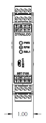
8 Outline Dimensions 7
9 Dynalco SST7000 Series Software The Dynalco host software provides serial communication between a PC or laptop and the SST7000 series. The software is compatible with Windows XP, Vista and Windows 7 operating systems. The SST7000 must be connected via Dynalco p/n 270A-XXXXX serial communication cable. This cable is sold separately. The Dynalco host software is available as a free download from our website: Following installation, a shortcut will be installed on your PC desktop. This application software allows access to various screens for configuration of input signal sensitivity, proportional output and relay logic / setpoints. Once the configuration parameters are set, they can be programmed into the SST7000 and a spec file can be saved to the PC. This saved spec file can then be loaded into another SST7000 if desired. Additionally, there is an import function allowing uploading of the spec file from an SST7000 to the PC. Configuration consists of the steps described in the following pages: 8
 magnetic pickups as well as 3-wire (powered, TTL or hall-effect) type sensors.")
10 RPM Signal The RPM Signal needs to be programmed prior to all other settings. The SST7000 series is capable of accepting input signals from 2-wire (also known as variable reluctance) magnetic pickups as well as 3-wire (powered, TTL or hall-effect) type sensors. The output from 2-wire pickups is an AC signal where the 3-wire type will normally have a positive-going (non zero-crossing) square wave output. Gear Teeth o Required to convert RPM to Hz for proper calibration Sensitivity Level o Set for Med-High for most applications o Higher sensitivity will allow greater sensitivity if needed for low speed applications o Lower sensitivity will be less sensitive to noise Max Wave Duration o The Max Wave Duration is defined as the maximum time allowed between input signal pulses before a sensor fault is declared. For example, a shaft with 2 keyways turning at 0 10 RPM would have an extremely low frequency range, calibrated below: Frequency = RPM X # teeth / 60 = 10 X 2 / 60 = Hz Then, the period (time in seconds between pulses) is calculated as: Period = 1 / Frequency = 1 / = 3 seconds In this example, the pulses would be received in time intervals of once every 3 seconds or longer. The Max Wave Duration can be configured to a maximum value of 10,000 milliseconds (10 seconds) to allow for this low speed range. Any pulse not received within 10 seconds would be considered a sensor fault. o Note that the default value of 1000 Milliseconds (1 second) is correct for most applications. 9

11 Signal Lost (SST7100 only) The signal lost function is defined as the absolute maximum allowable period (time between input pulses in milliseconds) before an under speed relay is tripped. Similar to the Max Wave Duration described in the previous step, the Signal Lost is necessary for low speed applications where there is a programmed under speed trip. This setting should be set longer than the period (in milliseconds) of the under speed setpoint. Enable o Check this box to enable Signal Lost o If there is no under speed setpoint, leave un-checked Time Out o This is the maximum time (in milliseconds) allowed before an under speed trip is initiated. Trip o Select Setpoint 1 for the SST
12 Open Pickup (SST7100 only) The Open Pickup tab allows the user to select which relay (if any) will activate if an open pickup is sensed. Enable o Check this box to enable Open Pickup option Trip o Select Setpoint 1 for the SST

13 Analog Output The analog output tab is used to define the RPM range of the proportional 4 20 ma output. RPM Zero o Set to the RPM value corresponding to 4 ma output. o Normally set to 0 RPM but can be set to any value as long as it is lower than the RPM span. RPM Span o Set to the RPM value corresponding to 20 ma output. 12

14 Setpoint 1 (SST7100 only) The Setpoint 1 tab allows configuration of the relay setpoint and relay logic for the single relay on the SST7100. Enable o Check this box to enable setpoint 1 Relay Normal State o This is the normal relay state when not tripped o Either select normally Energized or normally De-Energized WARNING: For critical applications, it is highly recommended to configure the Relay Normal State as normally Energized. This configuration will cause the contacts to switch in the event of a relay coil failure. Latching o Un-check this box to select non-latching relay (auto-reset following trip) o Check this box to select latching relay (must be manually reset following trip) o A momentary contact from DIG IN (digital input) to VIN GND (supply ground) will reset latching relay Low RPM o Selects under speed setpoint o Set to 0 if no under speed setpoint required High RPM o Selects over speed setpoint Reset Low RPM o Defines the reset value following an under speed trip o Must be set at least 1% higher than Low RPM value to prevent relay chatter o Set to 0 if no under speed setpoint required Reset High RPM o Defines the reset value following an over speed trip o Must be set at least 1% lower than High RPM value to prevent relay chatter 13

15 Program Following initial configuration of the unit or any setting changes, you will need to select Program to program the new settings to the SST7000 / SST7100. Save File Selecting Save File allows the new settings to be saved to a file location on the PC. 14
16 Load File Any spec files that have been saved to the PC can be loaded to the SST7000 application by selecting Load File. Following this, you will need to select Program to write the new configuration to the SST7000. Import Settings Selection of Import Settings will upload the current settings to be read by the SST7000 series software. WARNING: The relay output on the SST7100 should be tested monthly for proper operation, especially if being used for engine overspeed shutdown or other critical function. 15
5450 NW 33rd Ave, Suite 104 Fort Lauderdale, FL Fruitland Ave Los Angeles, CA UM Channel Monitor.
 5450 NW 33rd Ave, Suite 104 Fort Lauderdale, FL 33309 3211 Fruitland Ave Los Angeles, CA 90058 UM-600 6-Channel Monitor Version 2 Installation and Operation Manual Rev. G P/N145F-12990 PCO 00007462 (c)
6-Channel Monitor. Installation and Operation Manual
 3211 Fruitland Ave Los Angeles, CA 90058 Catalyst Monitor 6-Channel Monitor Version 2 Installation and Operation Manual Rev. H P/N145F-12964 PCO - 00009743 (c) Copyright 2015, Barksdale, Inc. All Rights
MSR Level Control Relay Module Operating Instructions for Level Control Relay Module Model: MSR
 Operating Instructions for Level Control Relay Module Model: MSR MSR Operation Instructions Rev. Apr 07 Page 1/8 1. Note Please read and take note of these operating instructions before unpacking and commissioning.
Analyzer/Controller. ph/orp HART. Model 54e ph/orp ESSENTIAL INSTRUCTIONS WARNINGS RISK OF ELECTRICAL SHOCK
 Instruction Sheet PN 51A-54epH/rev J October 2010 ph/orp HART Model 54e ph/orp Analyzer/Controller For additional information, please visit our website at www.emersonprocess.com/raihome/liquid/. ESSENTIAL
Operating Instructions. For. Level Control Module. Model SSR 1000
 Operating Instructions For Level Control Module Model SSR 1000 SSR Operation Instructions Rev. 1 Jan 01 Page 1/7 1. Note Please read and take note of these operating instructions before unpacking and commissioning.
3690 N.W. 53rd Street Fort Lauderdale, FL SC-2124 SC-2124M. 24 Channel Universal Scanner. Installation and Operation Manual P/N 145F-11902
 3690 N.W. 53rd Street Fort Lauderdale, FL 33309 SC-2124 SC-2124M 24 Channel Universal Scanner Installation and Operation Manual P/N 145F-11902 Rev. 3.30 (c) Copyright 2000, Dynalco Controls All Rights
LAUREL ELECTRONICS, INC.
 LAUREL ELECTRONICS, INC. Laureate RTD Temperature Panel Meter / Controller Features Factory calibrated for 100Ω platinum, 10Ω copper & 120Ω nickel RTDs 2, 3 or 4-wire connection with lead resistance compensation
ACT-1B Series Panel Tachometer
 MONARCH INSTRUMENT Instruction Manual ACT-1B Series Panel Tachometer Printed in the U.S.A. Copyright 2009 Monarch Instrument, all rights reserved 1071-4843-111R 0909 15 Columbia Drive Amherst, NH 03031
CurrentWatch Current Sensors. EGF Series Ground Fault Sensors. Ground Fault Sensors with Solid-State or Mechanical Relay Outputs.
 CurrentWatch Current Sensors Ground Fault Sensors with Solid-State or Mechanical Relay s 1 Contents Overview.................... 1 Model Selection, Switches...... 2 Model Selection, Accessories... 3 Wiring
Operating instructions. Speed monitor D / / 2014
 Operating instructions Speed monitor D200 80005257 / 00 05 / 2014 Contents 1 Preliminary note...4 1.1 Symbols used...4 1.2 Warning signs used...4 2 Safety instructions...5 2.1 General...5 2.2 Target group...5
Y800 Plus Frequency, Rate & Period Meter With dual, independently field-scalable channels
 Y800 Plus Frequency, Rate & Period Meter With dual, independently field-scalable channels Description Features Frequencies from 0.005 Hz to 1 MHz 6-digit resolution at update rates up to 25/s Selectable
MYRIAD QLC 4-CHANNEL MONITOR/CONTROLLER INSTRUCTION MANUAL
 MYRIAD QLC 4-CHANNEL MONITOR/CONTROLLER INSTRUCTION MANUAL VISIT OUR WEBSITE SIGMACONTROLS.COM MYR QLC MANUAL 013114 2 TABLE OF CONTENTS INTRODUCTION 3 Ordering Information Specifications Features WIRING
TC Type Range Conformity Error. J -210 C to +760 C (-347 F to F) ±0.09 C (±0.16 F) K -244 C to C (-408 F to F) ±0.1 C (±0.
 ±0.09 C (±0.16 F) K -244 C to C (-408 F to F) ±0.1 C (±0.") LAUREL ELECTRONICS, INC. Laureate Thermocouple Panel Meter / Controller Features Factory calibrated for thermocouple types J, K, T, E, N, R, S Entire range of each thermocouple in one scale Highly accurate
LAUREL ELECTRONICS, INC. Laureate Thermocouple Panel Meter / Controller Features Factory calibrated for thermocouple types J, K, T, E, N, R, S Entire range of each thermocouple in one scale Highly accurate
Operating Instructions. Intrinsically Safe Isolation Relay for Switches Model: REL manual_rel-6_0505
 Operating Instructions Intrinsically Safe Isolation Relay for Switches Model: REL-6003 manual_rel-6_0505 1. Contents 1. Contents...2 2. Note...3 3. Instrument Inspection...3 4. Regulation Use...3 5. Operating
Tempco Instruction Manual
 Tempco Instruction Manual 1/16 DIN Solid State Temperature Controller Relay Output Solid State Output For Heating Model Numbers: TEC-901, TEC-902, TEC-905 Temperature controls in this series are designed
LAUREL. Laureate RTD Temperature Panel Meter / Controller ELECTRONICS, INC. Features. Description. Specifications
 LAUREL ELECTRONICS, INC. Laureate RTD Temperature Panel Meter / Controller Features Factory calibrated for 100Ω platinum, 10Ω copper & 120Ω nickel RTDs 2, 3 or 4-wire connection with lead resistance compensation
LAUREL ELECTRONICS, INC.
 Description LAUREL ELECTRONICS, INC. Laureate Pulse or Analog Input Batch Controller Automatic batch control for repetitive liquid fill operations Features Available for turbine flow meter pulse signals
FLOW MONITOR & TRANSMITTER
 FLS M9.02 FLOW MONITOR & TRANSMITTER SAFETY INSTRUCTIONS General Statements Do not install and service the product without following the Instruction Manual. This item is designed to be connected to other
TABLE OF CONTENTS INTRODUCTION. 3. Analog Input Analog Output Digital Input Digital Output OPERATIONAL DESCRIPITON.. 7 PROGRAMMING AND INITIAL SETUP.
 DIVERSIFIED HEAT TRANSFER SERIES 700 STEAM GENERATOR CONTROLLER INSTRUCTION MANUAL VISIT OUR WEBSITE AT SIGMACONTROLS.COM SERIES 700 DHT STEAM GENERATOR MANUAL 042514 2 TABLE OF CONTENTS INTRODUCTION.
PT2060 Monitor. PT2060/91 SIM System Interface Module. Specifications. Electrical. Messtechnik
 PT2060/ System Interface Module ProvibTech s PT2060/ module is a communication and system interface module. This module is used to: module. The two phase reference channels can be used to provide phase
dual-line 6-dIGIt process MeteR
 dual-line 6-dIGIt process MeteR ProVu Se r i e S provu Model pd6000 0-20 ma, 4-20 ma, 0-5 V, 1-5 V, and ±10 V Inputs NEMA 4X, IP65 Front Universal 85-265 VAC or 12/24 VDC Input Power Large Dual-Line 6-Digit
EMS467 Monitoring System. Installation and Operations Manual Section 40
 EMS467 Monitoring System Installation and Operations Manual 00-02-0672 01-26-10 Section 40 In order to consistently bring you the highest quality, full featured products, we reserve the right to change
LAUREL. Laureate Rate Meter & Totalizer with Functions A+B, A-B, AxB, A/B, A/B-1 ELECTRONICS, INC. Features. Description
 Description LAUREL ELECTRONICS, INC. Features Laureate Rate Meter & Totalizer with Functions A+B, A-B, AxB, A/B, A/B-1 Arithmetic functions A+B, A-B, AxB, A/B, A/B-1 applied to rate or total for channels
Signet ph/orp Transmitter * *
 Loop 7 6 5 Signet 8750- ph/orp *-8750.090-* CAUTION! Contents 0.0 ph 5.0C Signet ph/orp. Installation. Panel Installation gasket panel terminals mounting bracket 96 mm (.8 in.) 8050 8 mm (. in.) Optional
...Introduction TACHLINK Tachpak 10 & 30 (T77510 & T77530) Tachtrol 10 & 30 (T77610 & T77630)... 10
 Tachtrol 10 & 30 (T77610 & T77630)... 10") Table of Contents Tachometers...Introduction........................... 1...TACHLINK........................... 4...Tachpak 10 & 30 (T77510 & T77530)....... 5...Tachtrol 10 & 30 (T77610 & T77630).......
Table of Contents Tachometers...Introduction........................... 1...TACHLINK........................... 4...Tachpak 10 & 30 (T77510 & T77530)....... 5...Tachtrol 10 & 30 (T77610 & T77630).......
NSGV Series "90DM3" Carbon Dioxide Detector
 NSGV SERIES 90DM3 CARBON DIOXIDE DETECTOR NSGV Series "90DM3" Carbon Dioxide Detector 90DM3A Specifications. Power 17-27 VAC, 24-38 VDC, 200 ma Detection Range 0-200 PPM Relay Output Rating 5A, 30 Vdc
Tachometer Panel, PE3
 Features Plug-n-play units with factory programmed parameters 4-20 ma feedback signal Isolated relay alarm outputs Frequency input Diagnostic indicators NEMA 4 Enclosure Model PE3, Tachometer Panel Benefits
Series 8000 RF Signal Switch Solution
 RF Signal Switch Solution Operation Manual Operation Manual, Part Number 07508000 006, Rev. B, Oct 7, 2014 All technical data and specifications in this publication are subject to change without prior
DEEP SEA ELECTRONICS PLC DSE103 MK II Speed Switch Operators Manual
 DEEP SEA ELECTRONICS PLC DSE103 MK II Speed Switch Operators Manual Document number 057-135 Author : Paul Gibbons DSE103 MKII Operator Manual Issue 1 Deep Sea Electronics Plc Highfield House Hunmanby North
LAUREL. Laureate Pulse or Analog Input Batch Controller Automatic batch control for repetitive liquid fill operations ELECTRONICS, INC.
 Description LAUREL ELECTRONICS, INC. Laureate Pulse or Analog Input Batch Controller Automatic batch control for repetitive liquid fill operations Features Available for turbine flow meter pulse signals
PGR-6101 MANUAL GROUND-FAULT & INSULATION MONITOR
 Tel: +1-800-832-3873 E-mail: techline@littelfuse.com www.littelfuse.com PGR-6101 MANUAL GROUND-FAULT & INSULATION MONITOR Revision 0-C-041918 Copyright 2018 by Littelfuse, Inc. All rights reserved. Document
Basic Temperature and Limit Controllers
 Basic Temperature and Limit Controllers Basic Temperature and Limit Controller Provide Economical Solution for a Wide Range of Applications The basic and limit microprocessor-based controllers from Watlow
SWTD-1000 Speed Switch / Transmitter Operating Manual
 SWTD-1000 Speed Switch / Transmitter Operating Manual 3690 NW 53 rd Street Fort Lauderdale, FL 33309 Ph 954-739-4300 Fax 954-486-4968 www.dynalco.com TABLE OF CONTENTS 1. Safety Instructions 1 2. Product
The PM1000 series is a universal 4 digit LED plug-on display for transmitters with 4-20mA 2 wire output and fitted with DIN43650 connector.
 PM1000 SERIES PLUG-ON DISPLAY BRIGHT LED DISPLAY INDICATION RANGE -999 TO +9999 FITS TO DIN 43650 CONNECTOR PLUG-ON TO ANY TRANSMITTER WITH 4-20MA OUTPUT EASY TO SCALE ON SITE ROBUST DESIGN SET POINT OPTION
Basic Temperature and Limit Controllers. Provide Economical Solution for a Wide Range of Applications SPECIFICATION SHEET
 SPECIFICATION SHEET Basic Temperature and Limit Controllers Basic Temperature and Limit Controllers Provide Economical Solution for a Wide Range of Applications The basic and limit microprocessor-based
+GF+ SIGNET ph/orp Transmitter Instructions
 GF SIGNET 8750 ph/orp Transmitter Instructions ENGLISH 8750.090 A9/99 English CAUTION! Remove power to unit before wiring input and output connections. Follow instructions carefully to avoid personal injury.
SFY Functional Safety Frequency-to-DC Transmitter with Display
 Functional Safety -to-dc March 2017 Description The SFY Functional Safety SIL 3 capable -to-dc is part of Moore Industries FS Functional Safety Series. It monitors frequency, period, high or low pulse
GFC114. Low Power Flow Computer FEATURES
 Low Power Flow Computer FEATURES l UNIVERSAL INPUT, 5 khz, CAN POWER THE l SIMPLIFIED MENUS AND PROGRAMMING l NO NEED OF AMPLIFIERS OR LINEARIZERS l SEVEN DIGIT RATE WITH PROGRAMMABLE DECIMAL PLACES l
TECHNICAL DATASHEET #TDAX023300
 Preliminary TECHNICAL DATASHEET #TDAX023300 2 Universal Inputs, Dual Universal Valve Controller 2 Universal Inputs 2-3A Outputs CAN (SAE J1939) Configurable with Electronic Assistant P/N: AX023300 Features
Plus-X 300. Installation and Operation Manual
 Plus-X 300 Installation and Operation Manual Table of Contents Introduction... 1 Compatibility... 1 Installation... 1 Configuration... 2 Operation... 5 Getting Help... 6 Warranty... 6 Appendix A: Specifications...
Instruction Manual ITC-79-FTF 0-10 VDC. Thresholds: ON: TP1=3V OFF: TP2=1V ON: TP1= OFF: TP2= 100 microsec. Not Installed.
 Manufacturers of Process Controls and Instrumentation Instruction Manual Model: ITC-79-FTF Function: Frequency to Frequency Isolator Option: Input: -DIV (Frequency Divider) -BUF (Frequency/Pulse Buffer)
INSTALLATION MANUAL. LC 200 Electronic Overload Guard. Software versione PW0501 R 0.3
 INSTALLATION MANUAL LC 200 Electronic Overload Guard Software versione PW0501 R 0.3 CONTENTS MAIN FEATURES LC 200 TECHNICAL FEATURES Page 2 SYMBOLS Page 3 WARNINGS Page 3 IDENTIFICATION DATA PLATE Page
PGR-3200 MANUAL INSULATION MONITOR
 Tel: +1-800-832-3873 E-mail: techline@littelfuse.com www.littelfuse.com PGR-3200 MANUAL INSULATION MONITOR REVISION 3-E-040918 Copyright 2018 by Littelfuse, Inc. All rights reserved. Document Number: PM-1025-EN
CRAGG RAILCHARGER Instruction Manual for 10DTC-12V 20DTC-12V 30DTC-24V 40DTC-12V 60DTC-12V
 CRAGG RAILCHARGER for 10DTC-12V 20DTC-12V 30DTC-24V 40DTC-12V 60DTC-12V Contents 1 Warnings, Cautions, and Notes... 1 2 Description... 2 3 Features... 2 3.1 STANDARD FEATURES... 2 3.2 CHARGER REGULATION...
Series 8000 RF Signal Switch Solution
 RF Signal Switch Solution Operation Manual Operation Manual, Part Number 07508000-006, Rev. A, May 17, 2013 All technical data and specifications in this publication are subject to change without prior
Series Watt DC Power Supplies
 Keithley Instruments 28775 Aurora Road Cleveland, Ohio 44139 1-800-935-5595 http://www.keithley.com Series 2268 850-Watt DC Power Supplies Specifications SPECIFICATION CONDITIONS This document contains
MP-2000 Dual Channel LVDT/RVDT Readout/Controller
 Large backlit dual channel display Menu driven setup and calibration 100 to 240 VAC line powered MIN, MAX, TIR, A+B and A-B functions 2.5, 3.3, 5 and 10kHz selectable excitation Analog and RS232 outputs
MCCB-500 MOLDED-CASE CIRCUIT BREAKER TESTER
 MCCB-500 MOLDED-CASE CIRCUIT BREAKER TESTER USER S MANUAL Vanguard Instruments Company, Inc. 1520 S. Hellman Ave. Ontario, California 91761, USA TEL: (909) 923-9390 FAX: (909) 923-9391 January 2015 Revision
NEUROLOGIC RESEARCH CORPORATION MODEL 2500
 NEUROLOGIC RESEARCH CORPORATION MODEL 2500 NETWORK HUMISTAT Compact, self-contained dehumidifier controller. 0.5 degrees C accuracy typical. RH sensor is digitally calibrated for 2% accuracy. Open communication
PGR-4300 MANUAL GENERATOR GROUND-FAULT RELAY
 Tel: +1-800-832-3873 E-mail: techline@littelfuse.com www.littelfuse.com PGR-4300 MANUAL GENERATOR GROUND-FAULT RELAY REVISION 3-B-041318 Copyright 2018 by Littelfuse, Inc. All rights reserved. Document
D115 The Fast Optimal Servo Amplifier For Brush, Brushless, Voice Coil Servo Motors
 D115 The Fast Optimal Servo Amplifier For Brush, Brushless, Voice Coil Servo Motors Ron Boe 5/15/2014 This user guide details the servo drives capabilities and physical interfaces. Users will be able to
INSTALLATION INSTRUCTIONS
 www.altroniccontrols.com INSTALLATION INSTRUCTIONS EXACTA 21 MONITORING AND CONTROL SYSTEM CAUTION: The EXACTA 21 CONTROL SYSTEM is CSA CERTIFIED FOR use in Class I, GROUPS C & D, Division 2 hazardous
EnCell Battery Cell Monitor
 EnCell Battery Cell Monitor Instruction Manual Model RCM15S12 NERC Compliant YO R U H T PA TO Z O R E W O D N M I T E enchargepowersystems.com sales@enchargepowersystems.com (888) 407.5040 Contents 1 Warnings,
Manual# Installation Manual. 200E Series. DCU 210E/208E Engine Panel RP 210E/220E Remote Panel
 Manual# 1006495 Installation Manual 200E Series DCU 210E/208E Engine Panel RP 210E/220E Remote Panel Installation Manual for the Marine Pro 200E Series ~~~ DCU 210E/208E Diesel Engine Control Unit RP 210E/220E
Dual Channel Monitor for Measurement of Speed and Ratio with SIL1 requirements Series D224.xx
 D224 Dual Channel Monitor for Measurement of Speed and Ratio with SIL1 requirements Series D224.xx D224 Front View KEY FEATURES SIL1 / IEC 61508:2010 compliant Dual Channel Speed and Ratio Monitor with
FLS M9.06. ph/orp MONITOR
 FLS M9.06 /ORP MONITOR Safety Instructions General Statements Do not install and service the product without following the Instruction Manual. This item is designed to be connected to other instruments
HART Modem for USB. Features. Description. Datasheet HmUSB-01 December Ideal for configurations, data acquisition and digital control.
 HmUSB Description The Computer Modem HmUSB is a complete communication path for a HART network. It will enable personal computers to read and or configure data within HART devices. The computer USB connector
Standard Options. Model 4100 Position Indicating Meter. Three Phase Motor Control. Positran Transmitter
 Standard Options Model 4100 Position Indicating Meter A percent-of-full-travel meter is supplied with a trim potentiometer resistor, terminal block and connectors. A potentiometer is required in the actuator
STEP MOTOR DRIVER SMD-4.2DIN
 SMART MOTOR DEVICES http://www.smd.ee STEP MOTOR DRIVER SMD-4.2DIN manual SMDDIN.42.001 2018 1. Product designation Step motor controller SMD-4.2DIN is an electronic device designed to operate with 2 or
LAUREL. Laureate Dual-Channel Pulse Input Totalizer With Two Independently Scalable Input Channels & Presets ELECTRONICS, INC. Features.
 Description LAUREL ELECTRONICS, INC. Laureate Dual-Channel Pulse Input Totalizer With Two Independently Scalable Input Channels & Presets Features Frequencies up to 1 MHz Totals stored in non-volatile
WARNING. TTDJ Series Fully-Configurable Fault Annunciator Installation and Operations Manual
 TTDJ Series Fully-Configurable Fault Annunciator Installation and Operations Manual TTDJ-99062N Revised 04-04 Section 50 (00-02-0412) Please read the following information before installing. This installation
DCS-E 1kW Series, DLM-E 3kW & 4kW Power Supplies
 DCS-E 1kW Series, DLM-E 3kW & 4kW Power Supplies M51A Option: Isolated Analog Programming Manual Power Supplies Elgar Electronics Corporation 9250 Brown Deer Road San Diego, CA 92121-2294 1-800-73ELGAR
Series 8900 LAN. Operation Manual. Part Number (example configuration) Part Number (example configuration)
 Part Number (example configuration)") Series 8900 LAN Part Number 90570300 (example configuration) Part Number 90570300-001 (example configuration) Operation Manual Operation Manual, Part Number 07508900-001, Rev. B, February 26, 2013 All
Series 8900 LAN Part Number 90570300 (example configuration) Part Number 90570300-001 (example configuration) Operation Manual Operation Manual, Part Number 07508900-001, Rev. B, February 26, 2013 All
Flomatic Smart Card TM Model FDHC-100 (Digital High-Resolution Controller) Configuration and Operation Manual
 Configuration and Operation Manual") The Flomatic FDHC-100 is a high performance Digital positioner intended to control AC actuators, providing 450 points of resolution with quarter turn actuators ranging from 2 sec to 120 sec and rated for
The Flomatic FDHC-100 is a high performance Digital positioner intended to control AC actuators, providing 450 points of resolution with quarter turn actuators ranging from 2 sec to 120 sec and rated for
Isolated Process Current Input with Loop Power 7B35
 Isolated Process Current Input with Loop Power 7B35 FEATURES Single-channel signal conditioning current input module that interfaces with two-wire transmitters. Module provides a precision output of either
MODEL SW6000 & SM6100 CENELEC INSTRUCTIONS
 MODEL SW6000 & SM6100 CENELEC INSTRUCTIONS Installation Manual 1180 METRIX Experience Value 8824 Fallbrook Dr. Houston, TX 77064, USA Tel: 1-281-940-1802 After Hours Technical Assistance: 1-713-702-8805
P/N: AX Applications: power gen set engine control systems oil and gas equipment automation off-highway machine automation
 TECHNICAL DATASHEET #TDAX031200 11:9 CAN CONTROLLER 11 Inputs (Analog, Digital, Magnetic Pick Up, Universal Signal) 4 Relay, 4 Analog, 1 Valve Driver Outputs 2 CAN (SAE J1939) with Electronic Assistant
Multi-instrument Communication, MIC-2 MKII DIN Quick Start Guide
 Multi-instrument Communication, MIC-2 MKII DIN Quick Start Guide Warnings and legal information Installation and terminals Communication I/O options Alarming Utility software More information Specifications
I/O Expansion Module Installation & Reference
 Overview The In-Sight vision sensor supports up to ten discrete inputs and ten discrete outputs. Two inputs and two outputs are built-in to the In-Sight processor. The remaining eight inputs and outputs
Operating Instructions. Isolation Relay for Switches Model: RL manual_rl-6100_1116
 Operating Instructions Isolation Relay for Switches Model: RL-6100 1. Contents 1. Contents...2 2. Note...3 3. Instrument Inspection...3 4. Regulation Use...3 5. Operating Principle...4 6. Mechanical Connection...4
PGR-4700 MANUAL SENSITIVE GROUND-FAULT RELAY
 Tel: +1-800-832-3873 E-mail: techline@littelfuse.com www.littelfuse.com/pgr-4700 PGR-4700 MANUAL SENSITIVE GROUND-FAULT RELAY REVISION 2-B-032218 Copyright 2018 by Littelfuse, Inc. All rights reserved.
IPM500 Series QuickStart Manual
 IPM500 Series QuickStart Manual The Force of Innovation 10 Thomas Irvine, CA 92618 USA (949) 465-0900 FAX: (949) 465-0905 E-Mail: HTUfutek@futek.comUTH www.futek.com Manufacturer of Load Cells, Pressure
Operating Instructions. Power Supply & Latching Relay For Switches Model: RL manual_rl-6000_1016
 Operating Instructions Power Supply & Latching Relay For Switches Model: RL-6000 manual_rl-6000_1016 1. Contents 1. Contents...2 2. Note...3 3. Instrument Inspection...3 4. Regulation Use...3 5. Operating
Trident and Trident X2 Digital Process and Temperature Panel Meter
 Sign In New User ISO 9001:2008 Certified Quality System Home Products Online Tools Videos Downloads About Us Store Contact Policies Trident and Trident X2 Digital Process and Temperature Panel Meter Products
+GF+ SIGNET Conductivity/Resistivity Transmitter Instructions
 GF SIGNET 8850 Conductivity/Resistivity Transmitter Instructions ENGLISH 8850.090 A9/99 English CAUTION! Remove power to unit before wiring input and output connections. Follow instructions carefully to
KILOVAC WD Series, DIN Rail or Screw Mounted Protective Relays
 KILOVAC WD Series, DIN Rail or Screw Mounted Protective Relays n WD25 Paralleling (Synch Check) Relays n WD2759 Over/undervoltage Relays n WD32 Reverse Power Relays n WD47 Phase Sequence Relays n WD5051
TPE 1464 Series Pressure Transducer
 TPE 1464 Series Pressure Transducer Description The KMC TPE 1464 series of pressure transducers incorporate a gauge pressure transmitter featuring low hysteresis, excellent repeatability, and longterm
Peak/Valley Hold Unit (PVHU) User Manual V3.00
 User Manual V3.00") Peak/Valley Hold Unit (PVHU) User Manual V3.00 Part Number: DO-UM0084/30/UE Applies to Firmware Version: V3.01 Reference: Peak_Valley Hold Unit (PVHU) User Manual.docx Date: 30 May 2016 Version: 3.00 Peak/Valley
Peak/Valley Hold Unit (PVHU) User Manual V3.00 Part Number: DO-UM0084/30/UE Applies to Firmware Version: V3.01 Reference: Peak_Valley Hold Unit (PVHU) User Manual.docx Date: 30 May 2016 Version: 3.00 Peak/Valley
iothinx 4500 Series (45MR) Modules
 Modules") iothinx 4500 Series (45MR) Modules Modules for iothinx 4500 Series Feature and Benefits Easy tool-free installation and removal Built-in LED indicators for IO channels Wide operating temperature range:
iothinx 4500 Series (45MR) Modules Modules for iothinx 4500 Series Feature and Benefits Easy tool-free installation and removal Built-in LED indicators for IO channels Wide operating temperature range:
Operation Manual CX10 1/8 DIN Microcomputer Based Conductivity/Resistivity Controller
 Operation Manual CX10 1/8 DIN Microcomputer Based Conductivity/Resistivity Controller 11751 Markon Drive Garden Grove, CA. 92841 U.S.A. pg. 1 CONTENTS GENERAL INTRODUCTION.....3 INITIAL INSPECTION......3
SE-703 MANUAL EARTH-LEAKAGE MONITOR
 Tel: +1-800-832-3873 E-mail: techline@littelfuse.com www.littelfuse.com/se-703 SE-703 MANUAL EARTH-LEAKAGE MONITOR REVISION 12-B-092117 Copyright 2017 by Littelfuse Startco All rights reserved. Document
FL MC 2000E (SM40) LC
 LC") IEC 61850 fiber optic converter with LC fiber optic connection (1310 nm) to convert 100Base-Tx to single- or multi-mode fiber glass Data sheet 3205_en_C 1 Description PHOENIX CONTACT 2014-04-04 2 Features
IEC 61850 fiber optic converter with LC fiber optic connection (1310 nm) to convert 100Base-Tx to single- or multi-mode fiber glass Data sheet 3205_en_C 1 Description PHOENIX CONTACT 2014-04-04 2 Features
INSTRUCTION MANUAL STATION CONTROLLER SC1000 MOTOR PROTECTION ELECTRONICS, INC.
 INSTRUCTION MANUAL STATION CONTROLLER SC1000 MOTOR PROTECTION ELECTRONICS, INC. 2464 Vulcan Road, Apopka, Florida 32703 Phone: (407) 299-3825 Fax: (407) 294-9435 Revision Date: 9-11-08 Applications: Simplex,
FLS M9.06 PH/ORP MONITOR. safety instructions. packing List
 FLS M9.06 PH/ORP MONITOR safety instructions General Statements Do not install and service the product without following the Instruction Manual. This item is designed to be connected to other instruments
CDD4 Series Room CO2 Transmitter Installation Instructions
 CDD4 Series Room CO2 Transmitter Installation Instructions Introduction The CO2 transmitter uses Infrared Technology to monitor CO2 levels and outputs a linear 4-20 ma or 0-5/0-10 Vdc signal. Options include
DIGITAL METERS Universal Analog Input Process Meter With Rate/Totalizer/Batch Control Features Instruction Manual
 DIGITAL METERS Universal Analog Input Process Meter With Rate/Totalizer/Batch Control Features 4-20 ma, 1-5 V, 0-5 V, or 0-10 V Field Selectable Inputs Full Six Digit Display for Total, 4½ Digit + Extra
DIGITAL PANEL METERS
 DIGITAL PANEL METERS 3 1/2 digit,4 1/2 digit - A/C D/C Voltage/Current 3 1/2 digit4 1/2 digit- AC/DCVoltage/Current-TRMS DPM U AC/DC VOLTAGE / CURRENT 3 1/2 DIGIT - MODEL : PE 3000 4 1/2 DIGIT - MODEL
SWT-2000 Frequency Measurement and Switching Instrument Operating Manual
 SWT-2000 Frequency Measurement and Switching Instrument Operating Manual 3690 NW 53 rd Street Fort Lauderdale, FL 33309 Ph 954-739-4300 Fax 954-486-4968 www.dynalco.com TABLE OF CONTENTS 1. Product Features
SINGLE-CHANNEL PROCESS CONTROLLERS & TEMP. DISPLAYS D3820/D3830 Series
 The Digitec Series D3800 Panel Meters offer many features and performance capabilities to suit a wide range of industrial applications. The D3820 and D3830 are available in the ranges of 4-20mA, 0-10 VDC,
INSTALLATION INSTRUCTIONS
 LIGHTING CONTROL PANELS 16 AND 24 RELAYS INSTALLATION INSTRUCTIONS INSTALLATION OVERVIEW The installation instructions contained in this document are provided as a guide for proper and reliable installation.
CDD Carbon Dioxide Transmitter
 Introduction The OSA CO2 transmitter uses Infrared Technology to monitor CO2 levels within a range of 0 2000 ppm and outputs a linear 4-20 ma or 0-5/0-10 Vdc signal. The enclosure is designed to operate
MiG2 CONTROLLERS. 2 & 4 Stage General Purpose Controllers, with Air-conditioning Facilities
 MiG2 CONTROLLERS 2 & 4 Stage General Purpose Controllers, with Air-conditioning Facilities The MiG2 controllers incorporate: 2 Inputs (Configurable as Resistive, 0 10V, 0 20mA or 4 20mA) 2 or 4 Relay Outputs
ME15 Magnetic Encoder Manual Revision 1.1
 Product Overview The ME15 Magnetic Encoder is the newest addition to AMCI s Encoder product line. The encoder is designed for lower resolution and lower cost applications and provides 10 bits of resolution.
Vibration Switches viib
 Vibration Switches technivib -- Z.I de Pringy -- 531 route des vernes 74 370 PRINGY France Tél :: 0033 4 50 01 23 20. Fax :: 0033 4 50 01 57 81 e.mail :: info@technivib.com Website : : www.technivib.com
1/32-DIN TEMPERATURE CONTROLLER INSTALLATION, WIRING AND OPERATION MANUAL FORM 3882
 1/32-DIN TEMPERATURE CONTROLLER INSTALLATION, WIRING AND OPERATION MANUAL FORM 3882 This manual is intended for use in support of installation, commissioning and configuration of the 1/32-DIN Temperature
IPM650 Intelligent Panel-Mount Display
 Quick Start Guide IPM650 Intelligent Panel-Mount Display Sensor Solutions Source Load Torque Pressure Multi Component Calibration Instruments Software www.futek.com Getting Help TECHNICAL SUPPORT For more
MCCB-250 MOLDED-CASE CIRCUIT BREAKER TESTER
 MCCB-250 MOLDED-CASE CIRCUIT BREAKER TESTER USER S MANUAL Vanguard Instruments Company, Inc. 1520 S. Hellman Ave. Ontario, California 91761, USA TEL: (909) 923-9390 FAX: (909) 923-9391 January 2015 Revision
PERFORMANCE SPECIFICATION SHEET
 PERFORMANCE SPECIFICATION SHEET INCH-POUND 1 April 2005 SUPERSEDING MIL-PRF-39016/18G 20 July 1988 RELAYS, ELECTROMAGNETIC, ESTABLISHED RELIABILITY, DPDT, LOW LEVEL TO 1.0 AMPERE WITH INTERNAL DIODE FOR
TFX PC Power Specifications
 TFX PC Power Specifications Model: HK340-71FP Consumer:Huntkey File NO: 试 产 Prepared by: Rex Checked by: Zhi Wu Approved by: Zhi Wu Issue date: 2010-03-29 REV:02 Model:HK340-71FP P/N:P15-3407100R Page
Manual# Installation Manual. 400E Series. DCU 410E Engine Control Unit RP 410E Remote Panel
 Manual# 1100346 Installation Manual 400E Series DCU 410E Engine Control Unit RP 410E Remote Panel RP 410E DCU 410E Installation Manual for Marine Pro 400E Series ~~~ DCU 410E Engine Control Unit RP 410E