EtherNet/IP TM Compatible Fieldbus System
|
|
|
- Lindsay Webster
- 6 years ago
- Views:
Transcription
1 PRODUCT NAME EtherNet/IP TM Compatible Fieldbus System MODEL / Series / Product Number EX500-GEN2 EX500-S103 EX500-DXP#
2 Table of Contents Safety Instructions 3 Product Overview 9 System construction 9 EX500 GW unit Model Indication and How to Order 10 Summary of Product parts 10 Mounting and Installation 11 Installation 11 Wiring 12 LED Display 17 Setting of EtherNet/IP TM using RSLogix5000 TM 20 I/O memory map 22 Web server function 30 Specification 39 Specifications 39 Dimensions 41 SI unit Model Indication and How to Order 42 Summary of Product parts 42 Mounting and Installation 43 Installation 43 Separate power supply 46 LED Display and Settings 47 Specification 48 Specifications 48 Dimensions
3 Input unit Model Indication and How to Order 50 Summary of Product parts 50 Mounting and Installation 51 Installation 51 Wiring 52 LED Display 58 Specification 59 Specifications 59 Dimensions 60 Interchangeability of system 61 Troubleshooting 65 Accessories
4 Safety Instructions These safety instructions are intended to prevent hazardous situations and/or equipment damage. These instructions indicate the level of potential hazard with the labels of "Caution", "Warning" or "Danger". They are all important notes for safety and must be followed in addition to International standards (ISO/IEC) 1) and other safety regulations. 1) ISO 4414: Pneumatic fluid power -- General rules relating to systems ISO 4413: Hydraulic fluid power -- General rules relating to systems IEC : Safety of machinery -- Electrical equipment of machines (Part 1: General requirements) ISO : Manipulating industrial robots -Safety. etc. Caution : Warning : Danger : CAUTION indicates a hazard with a low level of risk which, if not avoided, could result in minor or moderate injury. WARNING indicates a hazard with a medium level of risk which, if not avoided, could result in death or serious injury. DANGER indicates a hazard with a high level of risk which, if not avoided, will result in death or serious injury. Warning 1. The compatibility of the product is the responsibility of the person who designs the equipment or decides its specifications. Since the product specified here is used under various operating conditions, its compatibility with specific equipment must be decided by the person who designs the equipment or decides its specifications based on necessary analysis and test results. The expected performance and safety assurance of the equipment will be the responsibility of the person who has determined its compatibility with the product. This person should also continuously review all specifications of the product referring to its latest catalog information, with a view to giving due consideration to any possibility of equipment failure when configuring the equipment. 2. Only personnel with appropriate training should operate machinery and equipment. The product specified here may become unsafe if handled incorrectly. The assembly, operation and maintenance of machines or equipment including our products must be performed by an operator who is appropriately trained and experienced. 3. Do not service or attempt to remove product and machinery/equipment until safety is confirmed. 1. The inspection and maintenance of machinery/equipment should only be performed after measures to prevent falling or runaway of the driven objects have been confirmed. 2. When the product is to be removed, confirm that the safety measures as mentioned above are implemented and the power from any appropriate source is cut, and read and understand the specific product precautions of all relevant products carefully. 3. Before machinery/equipment is restarted, take measures to prevent unexpected operation and malfunction. 4. Contact SMC beforehand and take special consideration of safety measures if the product is to be used in any of the following conditions. 1. Conditions and environments outside of the given specifications, or use outdoors or in a place exposed to direct sunlight. 2. Installation on equipment in conjunction with atomic energy, railways, air navigation, space, shipping, vehicles, military, medical treatment, combustion and recreation, or equipment in contact with food and beverages, emergency stop circuits, clutch and brake circuits in press applications, safety equipment or other applications unsuitable for the standard specifications described in the product catalog. 3. An application which could have negative effects on people, property, or animals requiring special safety analysis. 4. Use in an interlock circuit, which requires the provision of double interlock for possible failure by using a mechanical protective function, and periodical checks to confirm proper operation
5 Caution The product is provided for use in manufacturing industries. The product herein described is basically provided for peaceful use in manufacturing industries. If considering using the product in other industries, consult SMC beforehand and exchange specifications or a contract if necessary. If anything is unclear, contact your nearest sales branch. Limited warranty and Disclaimer/Compliance Requirements The product used is subject to the following "Limited warranty and Disclaimer" and "Compliance Requirements". Read and accept them before using the product. Limited warranty and Disclaimer 1. The warranty period of the product is 1 year in service or 1.5 years after the product is delivered, whichever is first. 2) Also, the product may have specified durability, running distance or replacement parts. Please consult your nearest sales branch. 2. For any failure or damage reported within the warranty period which is clearly our responsibility, a replacement product or necessary parts will be provided. This limited warranty applies only to our product independently, and not to any other damage incurred due to the failure of the product. 3. Prior to using SMC products, please read and understand the warranty terms and disclaimers noted in the specified catalog for the particular products. 2) Vacuum pads are excluded from this 1 year warranty. A vacuum pad is a consumable part, so it is warranted for a year after it is delivered. Also, even within the warranty period, the wear of a product due to the use of the vacuum pad or failure due to the deterioration of rubber material are not covered by the limited warranty. Compliance Requirements 1. The use of SMC products with production equipment for the manufacture of weapons of mass destruction (WMD) or any other weapon is strictly prohibited. 2. The exports of SMC products or technology from one country to another are governed by the relevant security laws and regulation of the countries involved in the transaction. Prior to the shipment of a SMC product to another country, assure that all local rules governing that export are known and followed
6 Operator This operation manual is intended for those who have knowledge of machinery using pneumatic equipment, and have sufficient knowledge of assembly, operation and maintenance of such equipment. Only those persons are allowed to perform assembly, operation and maintenance. Read and understand this operation manual carefully before assembling, operating or providing maintenance to the product. Safety Instructions Warning Do not disassemble, modify (including changing the printed circuit board) or repair. An injury or failure can result. Do not operate the product outside of the specifications. Do not use for flammable or harmful fluids. Fire, malfunction, or damage to the product can result. Verify the specifications before use. Do not operate in an atmosphere containing flammable or explosive gases. Fire or an explosion can result. This product is not designed to be explosion proof. If using the product in an interlocking circuit: Provide a double interlocking system, for example a mechanical system. Check the product regularly for proper operation. Otherwise malfunction can result, causing an accident. The following instructions must be followed during maintenance: Turn off the power supply. Stop the air supply, exhaust the residual pressure and verify that the air is released before performing maintenance. Otherwise an injury can result
7 Caution After maintenance is complete, perform appropriate functional inspections. Stop operation if the equipment does not function properly. Safety cannot be assured in the case of unexpected malfunction. Provide grounding to assure the safety and noise resistance of the Serial System. Individual grounding should be provided close to the product with a short cable. NOTE Follow the instructions given below when designing, selecting and handling the product. The instructions on design and selection (installation, wiring, environment, adjustment, operation, maintenance, etc.) described below must also be followed. Product specifications The direct current power supply to combine should be UL1310 Class 2 power supply when conformity to UL is necessary. The product is a UL approved product only if they have a mark on the body. Use the specified voltage. Otherwise failure or malfunction can result. Reserve a space for maintenance. Allow sufficient space for maintenance when designing the system. Do not remove any nameplates or labels. This can lead to incorrect maintenance, or misreading of the operation manual, which could cause damage or malfunction to the product. It may also result in non-conformity to safety standards
8 Product handling Installation Do not drop, hit or apply excessive shock to the fieldbus system. Otherwise damage to the product can result, causing malfunction. Tighten to the specified tightening torque. If the tightening torque is exceeded the mounting screws may be broken. IP65/67 protection cannot be guaranteed if the screws are not tightened to the specified torque. Never mount a product in a location that will be used as a foothold. The product may be damaged if excessive force is applied by stepping or climbing onto it. Wiring Avoid repeatedly bending or stretching the cables, or placing heavy load on them. Repetitive bending stress or tensile stress can cause breakage of the cable. Wire correctly. Incorrect wiring can break the product. Do not perform wiring while the power is on. Otherwise damage to the fieldbus system and/or I/O device can result, causing malfunction. Do not route wires and cables together with power or high voltage cables. Otherwise the fieldbus system and/or I/O device can malfunction due to interference of noise and surge voltage from power and high voltage cables to the signal line. Route the wires (piping) of the fieldbus system and/or I/O device separately from power or high voltage cables. Confirm proper insulation of wiring. Poor insulation (interference from another circuit, poor insulation between terminals, etc.) can lead to excess voltage or current being applied to the product, causing damage. Take appropriate measures against noise, such as using a noise filter, when the fieldbus system is incorporated into equipment. Otherwise noise can cause malfunction. Separate the power line for output devices from the power line for control. Otherwise noise or induced surge voltage can cause malfunction. Environment Select the proper type of protection according to the environment of operation. IP65/67 protection is achieved when the following conditions are met. (1) The units are connected properly with fieldbus cable with M12 connector and power cable with M12 (M8) connector. (2) Suitable mounting of each unit and manifold valve. If using in an environment that is exposed to water splashes, please take measures such as using a cover. If the product is to be used in an environment containing oils or chemicals such as coolant or cleaning solvent, even for a short time, it may be adversely affected (damage, malfunction etc.). Do not use the product in an environment where corrosive gases or fluids could be splashed. Otherwise damage to the product and malfunction can result. Do not use in an area where surges are generated. If there is equipment which generates a large amount of surge (solenoid type lifter, high frequency induction furnace, motor, etc.) close to the fieldbus system, this may cause deterioration or breakage of the internal circuit of the fieldbus system. Avoid sources of surge generation and crossed lines. When a surge-generating load such as a relay or solenoid is driven directly, use an fieldbus system with a built-in surge absorbing element. Direct drive of a load generating surge voltage can damage the fieldbus system. The product is CE marked, but not immune to lightning strikes. Take measures against lightning strikes in the system. Prevent foreign matter such as remnant of wires from entering the fieldbus system to avoid failure and malfunction
9 Mount the product in a place that is not exposed to vibration or impact. Otherwise failure or malfunction can result. Do not use the product in an environment that is exposed to temperature cycle. Heat cycles other than ordinary changes in temperature can adversely affect the inside of the product. Do not expose the product to direct sunlight. If using in a location directly exposed to sunlight, shade the product from the sunlight. Otherwise failure or malfunction can result. Keep within the specified ambient temperature range. Otherwise malfunction can result. Do not operate close to a heat source, or in a location exposed to radiant heat. Otherwise malfunction can result. Adjustment and Operation Perform settings suitable for the operating conditions. Incorrect setting can cause operation failure. Please refer to the PLC manufacturer's manual etc. for details of programming and addresses. For the PLC protocol and programming refer to the relevant manufacturer's documentation. Maintenance Turn off the power supply, stop the supplied air, exhaust the residual pressure and verify the release of air before performing maintenance. There is a risk of unexpected malfunction. Perform regular maintenance and inspections. There is a risk of unexpected malfunction. After maintenance is complete, perform appropriate functional inspections. Stop operation if the equipment does not function properly. Otherwise safety is not assured due to an unexpected malfunction or incorrect operation. Do not use solvents such as benzene, thinner etc. to clean the each unit. They could damage the surface of the body and erase the markings on the body. Use a soft cloth to remove stains. For heavy stains, use a cloth soaked with diluted neutral detergent and fully squeezed, then wipe up the stains again with a dry cloth
.")
10 Product Overview System construction The EX500 range of units can be connected to open fieldbus (EtherNet/IP TM ) to realize the reduction of input or output device wiring and the distributed control system. One branch of manifold valves/input unit can be connected to 32 outputs/32 inputs. Up to 4 branches can be connected (total 128 outputs/128 inputs)
11 EX500 GW unit Model Indication and How to Order Summary of Product parts No. Name Application 1 Communication connector (Port1/IN) 2 Communication connector (Port2/OUT) 3 Power supply connector 4 Branch port A(COM A) 5 Branch port B(COM B) 6 Branch port C(COM C) 7 Branch port D(COM D) 8 Display window Connect to EtherNet/IP TM line. 1 Connector to supply power to the output devices such as solenoid valves and input and control equipment such as sensors. 1 Connect the SI unit (with manifold valves) or input unit using a branch cable. 1 Displays the status of the power supply and the communication with the PLC. 2 9 Switch cover Sets the address, etc. with the switch inside Grounding terminal (FE) Used for functional grounding. (It is recommended to ground with resistance of 100 ohms or less) Accessories Seal cap: 5 pcs. (for M12 connector socket) 1: Refer to page 12 for wiring. 2: Refer to page 17 for display and setting. Used for unused communication connector and branch ports

12 Mounting and Installation Installation Direct mounting Install the product using 4 M5 screws x 15 mm or longer with a head ø5.2 minimum
13 Wiring Described as follows:- 1Communication wiring: Connection with EtherNet/IP TM 2Power supply wiring: Connection of the power supply for the solenoid valve and the power supply for input and control. 3Branch wiring: Connection from GW unit to SI unit or input unit. 1. Wiring for communication Connect the Ethernet communication cable to the communication connector. Communication connector pin layout (Port1/Port2) M12, 4 pin, socket, D code. No. Description 1 TX+ 2 RX+ 3 TX- 4 RX
 2 24 VDC (For input and control) 3 0 V (For input and control) 4 0 V (For solenoid valves) Power supply Either single or dual power supply can be used.")
14 2. Power supply wiring Connect a power supply cable to the power supply connector on the GW unit. Refer to page 6 for the selection of the power supply. Connector pin layout 7/8 inch, 4 pin, plug No. Description 1 24 VDC (For solenoid valves) 2 24 VDC (For input and control) 3 0 V (For input and control) 4 0 V (For solenoid valves) Power supply Either single or dual power supply can be used. Separate wiring for the solenoid valves and input / control is necessary. A. With separate power supplies B. With one power supply
15 Ground connection Note Connect the FE terminal to ground
16 3. Branch wiring Connect the valve manifold with SI unit or an input unit to a branch port (COM A to D) using a branch cable (cable with M12 connector). One branch port can be connected with up to 32 inputs and 32 outputs (Max. 4 units). Branch port (COM A to D) Note Be sure to fit a seal cap on any unused connectors of the GW unit. IP65 is maintained by using the seal cap. (Tightening torque: 0.1 Nm) [Connection example] Connecting a GW unit to a valve manifold with SI unit and to an input unit 2 pcs. of the connector for wiring the branch cable are prepared for each SI unit and Input unit. The branch cable from the GW unit is connected to the branch connector (IN). The cable to the next SI unit or input unit is connected to the branch connector (OUT)

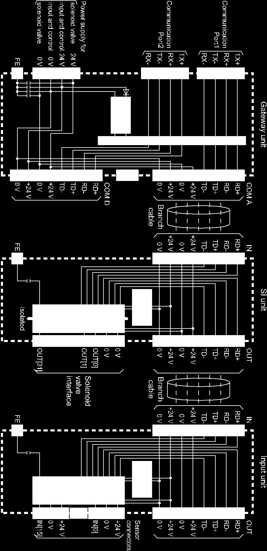
17 Internal circuit
18 LED Display Display MS NS PWR(V) PI L/A1 L/A2 COM A COM B COM C COM D LED is OFF Green LED is ON Green LED is flashing Red LED is flashing Red LED is ON LED is OFF Green LED is ON Green LED is flashing Red LED is flashing Red LED is ON LED is OFF Green LED is ON LED is OFF Orange LED is flashing Orange LED is ON LED is OFF Green LED is ON Green LED is flashing Orange LED is ON Orange LED is flashing LED is OFF Green LED is ON Green LED is flashing Orange LED is ON Orange LED is flashing LED is OFF Green LED is ON Green LED is flashing LED is OFF Green LED is ON Green LED is flashing LED is OFF Green LED is ON Green LED is flashing LED is OFF Green LED is ON Green LED is flashing Meaning The power supply for input and control is OFF Normal operation Parameter setting error Diagnostics error Unrecoverable error IP address not set EtherNet/IP TM communication established EtherNet/IP TM communication not established EtherNet/IP TM communications time out IP address has been duplicated Power supply for Solenoid valve is OFF Power supply for Solenoid valve is ON Forced output mode is disabled (Operating normally) Ethernet UCMP Echo request (Ping command) received. Forced output mode is ON No Link, No Activity (Port1) Link, No Activity (Port1, 100 Mbps) Link, Activity (Port1, 100 Mbps) Link, No Activity (Port1, 10 Mbps) Link, Activity (Port1, 10 Mbps) No Link, No Activity (Port2) Link, No Activity (Port2, 100 Mbps) Link, Activity (Port2, 100 Mbps) Link, No Activity (Port2, 10 Mbps) Link, Activity (Port2, 10 Mbps) Not connected Normal operation Diagnostics error Not connected Normal operation Diagnostics error Not connected Normal operation Diagnostics error Not connected Normal operation Diagnostics error
19 Switch setting Open the switch cover, and set the switches with a small flat blade screwdriver. Note 1. The power supply should be off while setting the switches. 2. The default setting is OFF or Whenever the switch cover has been opened, close the switch cover and tighten the screw to the specified torque. (Tightening torque: 0.6 Nm)
20 1: Remoto control The mode to respond to the commands below of BOOTP/DHCP Server provided by Rockwell Automation. Enable DHCP Information including IP address can be obtained from BOOTP/DHCP Server. If the power is supplied again in this state, EX500 tries to obtain the information including IP address again. Disable BOOTP/DHCP Information including IP address is not obtained from BOOTP/DHCP Server. Previous setting can be held if power is supplied under this condition. 2: Manual setting of IP address IP address is set within the range of to , to : DHCP mode Obtain IP address from DHCP Server. Obtained IP address is lost when power supply is cut. Default setting "Enable DHCP" at "Remote control". 4: See page 62. Note Remote Control mode If IP address EX500 held is unknown, restart GW unit in DHCP mode temporarily and return to Remote control mode. Though the previous IP address is lost when GW unit is in DHCP mode, new IP address can be obtained from BOOTP/DHCP server
21 Setting of EtherNet/IP TM using RSLogix5000 TM Method to connect a GW unit to the Rockwell Automation EtherNet/IP TM module (master) is shown below. Refer to the Operation Manual of the RSLogix5000 TM for the detailed operation. : This figure shows the display of Rockwell Automation software, RSLogix5000 TM. Select [EtherNet/IP TM module] in [I/O Configuration] folder, then select [New Module]. The [Select Module] screen is displayed. Select [ETHERNET-MODULE Generic Ethernet Module], then select [Create]
 IP Address: Enter the IP address setting for the GW unit. (4) Assembly Instance: Perform setting as shown below.")
22 The Module Properties screen is displayed. Perform each setting. (1) Name: Enter the required unit name. (2) Comm Format: Select the data format of Connection Parameters. (3) IP Address: Enter the IP address setting for the GW unit. (4) Assembly Instance: Perform setting as shown below. Item Decimal Common Format "Data-INT" "Data-SINT" Input Output Configuration (5) Size: Perform setting as shown below. Item Decimal Common Format "Data-INT" "Data-SINT" Input 10 (words) 20 (bytes) Output 10 (words) 20 (bytes) Configuration 0 or 34 (words) 0 or 68 (bytes) : Set 0 for Configuration Size when configuration data setting is not changed from the default value. Configuration data setting will be explained later. Configuration data setting can be changed by setting 34 (words) or 68 (bytes). Refer to page 28 for the configuration data map. (1) (4) (5) (2) (3)


23 Input data Diagnostic data I/O memory map I/O data Connection example Input data Input data Offset (INT) MSB LSB MSB LSB IN15 IN14 IN13 IN12 IN11 IN10 IN9 IN8 IN7 IN6 IN5 IN4 IN3 IN2 IN1 IN0 1 IN31 IN30 IN29 IN28 IN27 IN26 IN25 IN24 IN23 IN22 IN21 IN20 IN19 IN18 IN17 IN16 2 IN47 IN46 IN45 IN44 IN43 IN42 IN41 IN40 IN39 IN38 IN37 IN36 IN35 IN34 IN33 IN32 3 IN63 IN62 IN61 IN60 IN59 IN58 IN57 IN56 IN55 IN54 IN53 IN52 IN51 IN50 IN49 IN48 4 IN79 IN78 IN77 IN76 IN75 IN74 IN73 IN72 IN71 IN70 IN69 IN68 IN67 IN66 IN65 IN64 5 IN95 IN94 IN93 IN92 IN91 IN90 IN89 IN88 IN87 IN86 IN85 IN84 IN83 IN82 IN81 IN80 6 IN111 IN110 IN109 IN108 IN107 IN106 IN105 IN104 IN103 IN102 IN101 IN100 IN99 IN98 IN97 IN96 7 IN127 IN126 IN125 IN124 IN123 IN122 IN121 IN120 IN119 IN118 IN117 IN116 IN115 IN114 IN113 IN112 8 #D4 #D3 #D2 #D1 #C4 #C3 #C2 #C1 #B4 #B3 #B2 #B1 #A4 #A3 #A2 #A1 Meaning COM A COM B COM C COM D Slave condition Port 9 Error code COM_D COM_C COM_B COM_A diagnosis/ Error code
24 Output data Diagnostic setting Output data Offset (INT) Output data MSB LSB MSB LSB Meaning 0 OUT15 OUT14 OUT13 OUT12 OUT11 OUT10 OUT9 OUT8 OUT7 OUT6 OUT5 OUT4 OUT3 OUT2 OUT1 OUT0 1 OUT31 OUT30 OUT29 OUT28 OUT27 OUT26 OUT25 OUT24 OUT23 OUT22 OUT21 OUT20 OUT19 OUT18 OUT17 OUT16 2 OUT47 OUT46 OUT45 OUT44 OUT43 OUT42 OUT41 OUT40 OUT39 OUT38 OUT37 OUT36 OUT35 OUT34 OUT33 OUT32 3 OUT63 OUT62 OUT61 OUT60 OUT59 OUT58 OUT57 OUT56 OUT55 OUT54 OUT53 OUT52 OUT51 OUT50 OUT49 OUT48 4 OUT79 OUT78 OUT77 OUT76 OUT75 OUT74 OUT73 OUT72 OUT71 OUT70 OUT69 OUT68 OUT67 OUT66 OUT65 OUT64 5 OUT95 OUT94 OUT93 OUT92 OUT91 OUT90 OUT89 OUT88 OUT87 OUT86 OUT85 OUT84 OUT83 OUT82 OUT81 OUT80 6 OUT111 OUT110 OUT109 OUT108 OUT107 OUT106 OUT105 OUT104 OUT103 OUT102 OUT101 OUT100 OUT99 OUT98 OUT97 OUT96 7 OUT127 OUT126 OUT125 OUT124 OUT123 OUT122 OUT121 OUT120 OUT119 OUT118 OUT117 OUT116 OUT115 OUT114 OUT113 OUT112 8 #D4 #D3 #D2 #D1 #C4 #C3 #C2 #C1 #B4 #B3 #B2 #B1 #A4 #A3 #A2 #A COM_D COM_C COM_B COM_A -: Unused COM A COM B COM C COM D Slave connection diagnosis 32 point switch diagnosis
25 Diagnostic data Diagnostic information Offset (INT) Input data MSB LSB MSB LSB Meaning 8 #D4 #D3 #D2 #D1 #C4 #C3 #C2 #C1 #B4 #B3 #B2 #B1 #A4 #A3 #A2 #A1 Slave condition Port 9 Error code COM_D COM_C COM_B COM_A diagnosis/ Error code < Slave condition > < Port diagnosis > Value Slave condition Value Status 0 Not connected 0 OK 1 Connection port 1 ERR < Error code > Message code showing the diagnostic error and position code showing error location are stored. All 0 when no error has occurred. Position code (Order #1 - #4, Port A - D) Message code #4 #3 #2 #1 D C B A Message code 0x2 Product No.1 A port Ex.: Short-circuit or over current error with the first slave of COM A port. Message code and corrective action for diagnostic error are shown below. Message Code Name of Diagnostic error Meaning of Diagnostic Error 0x0 (No error) There is no error. 0x1 Short-circuit or over current (lost connection) Short circuit or over current of GW unit branch port input and control power supply. 0x2 Short-circuit or over current Short circuit or over current of input unit sensor connector. 0x3 More than 32 input More than 32 inputs are connected to 1 port. 0x4 More than 32 output More than 32 outputs are connected to 1 port. 0x5 More than 4 slaves More than 4 slaves are connected to 1 port. 0x6 0x7 Lost connection or configuration error Dip switch is not set to "32out." 0x8-0xF Reserve - Slave specified by the diagnostic setting "Slave connection diagnostic" is not connected. SI unit which is not 32 output is connected to the port specified by diagnostic setting < 32 point switch diagnostic >
26 Diagnostic setting Offset (INT) Output data MSB LSB MSB LSB Meaning 8 #D4 #D3 #D2 #D1 #C4 #C3 #C2 #C1 #B4 #B3 #B2 #B1 #A4 #A3 #A2 #A COM_D COM_C COM_B COM_A Slave connection diagnostic 32 point switch diagnostic -: Unused < Slave connection diagnostic > < 32 point switch diagnostic > Value Setting Value Setting 0 Disabled 0 Disabled 1 Enabled 1 Enabled : See page 26. : See page
 for the diagnostic bit of the slave connection. Refer to the figure below for the usage.")
27 < Slave connection diagnostic > Diagnostic function to detect the branch cable broken wire or incorrect configuration of the slave connection. Diagnostic error can be generated when the slave is not connected by setting "1" (enabled) for the diagnostic bit of the slave connection. Refer to the figure below for the usage. Offset (INT) 8 Output data MSB LSB MSB LSB Meaning #D4 #D3 #D2 #D1 #C4 #C3 #C2 #C1 #B4 #B3 #B2 #B1 #A4 #A3 #A2 #A1 Slave In the figure above, #A1 to #A3 are slaves for which the connection is diagnosed. In this case, #A3 slave is not connected, and a diagnostic error is generated. Here, the < Port diagnostic > of the input data is "1". Offset (INT) Input data MSB LSB MSB LSB connection diagnosis Meaning 8 9 #D4 #D3 #D2 #D1 #C4 #C3 #C2 #C1 #B4 #B3 #B2 #B1 #A4 #A3 #A2 #A1 Slave condition Error code COM_D COM_C COM_B COM_A Port diagnostic/ Error code
28 < 32 point switch diagnostic > Detect the incorrect setting of the SI unit switch. When a manifold with more than 17 valves is used, by setting "1" (enabled) to 32 point switch diagnostic bit, a diagnostic error can be generated when SI unit switch is set to 16 point output by mistake. Refer to the figure below for the usage. Offset (INT) 9 Output data MSB LSB MSB LSB Meaning Reserve COM_D COM_C COM_B COM_A 32 point switch diagnosis In the figure above, COM A is the subject of 32 point switch diagnostic. In this case, diagnostic error is generated as the SI unit of 16 point output setting is connected. Here, the < Port diagnostic > of the input data is "1". Offset (INT) Input data MSB LSB MSB LSB Meaning 8 9 #D4 #D3 #D2 #D1 #C4 #C3 #C2 #C1 #B4 #B3 #B2 #B1 #A4 #A3 #A2 #A1 Slave condition Error code COM_D COM_C COM_B COM_A Port diagnostic/ Error code
29 Configuration data map Offset (INT) Configuration data MSB LSB MSB LSB QC Web COM_D COM_C COM_B COM_A forcing diag diag diag diag 1 FA_OUT7 FA_OUT6 FA_OUT5 FA_OUT4 FA_OUT3 FA_OUT2 FA_OUT1 FA_OUT0 2 FA_OUT15 FA_OUT14 FA_OUT13 FA_OUT12 FA_OUT11 FA_OUT10 FA_OUT9 FA_OUT8 3 FA_OUT23 FA_OUT22 FA_OUT21 FA_OUT20 FA_OUT19 FA_OUT18 FA_OUT17 FA_OUT16 4 FA_OUT31 FA_OUT30 FA_OUT29 FA_OUT28 FA_OUT27 FA_OUT26 FA_OUT25 FA_OUT24 5 FA_OUT39 FA_OUT38 FA_OUT37 FA_OUT36 FA_OUT35 FA_OUT34 FA_OUT33 FA_OUT32 6 FA_OUT47 FA_OUT46 FA_OUT45 FA_OUT44 FA_OUT43 FA_OUT42 FA_OUT41 FA_OUT40 7 FA_OUT55 FA_OUT54 FA_OUT53 FA_OUT52 FA_OUT51 FA_OUT50 FA_OUT49 FA_OUT48 8 FA_OUT63 FA_OUT62 FA_OUT61 FA_OUT60 FA_OUT59 FA_OUT58 FA_OUT57 FA_OUT56 9 FA_OUT71 FA_OUT70 FA_OUT69 FA_OUT68 FA_OUT67 FA_OUT66 FA_OUT65 FA_OUT64 10 FA_OUT79 FA_OUT78 FA_OUT77 FA_OUT76 FA_OUT75 FA_OUT74 FA_OUT73 FA_OUT72 11 FA_OUT87 FA_OUT86 FA_OUT85 FA_OUT84 FA_OUT83 FA_OUT82 FA_OUT81 FA_OUT80 12 FA_OUT95 FA_OUT94 FA_OUT93 FA_OUT92 FA_OUT91 FA_OUT90 FA_OUT89 FA_OUT88 13 FA_OUT103 FA_OUT102 FA_OUT101 FA_OUT100 FA_OUT99 FA_OUT98 FA_OUT97 FA_OUT96 14 FA_OUT111 FA_OUT110 FA_OUT109 FA_OUT108 FA_OUT107 FA_OUT106 FA_OUT105 FA_OUT FA_OUT119 FA_OUT118 FA_OUT117 FA_OUT116 FA_OUT115 FA_OUT114 FA_OUT113 FA_OUT FA_OUT127 FA_OUT126 FA_OUT125 FA_OUT124 FA_OUT123 FA_OUT122 FA_OUT121 FA_OUT Reserve -: Unused < Configuration data > COM_A to COM_D diag: Select the output operation during a diagnostic error for each port. 0: Continue (Default) 1: Stop Web forcing: Limit the forced output function of Web server function. 0: Forced output is disabled while EtherNet/IP TM communication is established (default status). 1: Forced output is available while EtherNet/IP TM communication is established. QC: QuickConnect TM function can be selected. 1 0: Invalid (Default) 1: Enabled : When enabled, Auto-Negotiation (A-N) is disabled. The communication speed is 100 Mbps. Communication is fixed to full duplex. Make sure the value is set to "0" when the QuickConnect TM function is not used. FA_OUT0 to FA_OUT127: Hold or Clear of output can be set during EtherNet/IP TM communication error. 00: Clear (Default) 01: Forced output ON 1X: Hold : Make sure the switch No. 2 is OFF when this configuration data is used. See page
30 1: EtherNet/IP TM QuickConnect TM function This GW unit can be used as an EtherNet/IP TM compliant node for networks with the QuickConnect TM function. To enable the QuickConnect TM function, it is necessary to perform the settings 1 to 2 to the GW unit as shown below. After satisfying the conditions 1 to 2, setting of the QuickConnect TM function compliant EtherNet/IP TM module (master), according to the specified procedure, must be performed. Refer to the manual for the EtherNet/IP TM module (master) for the specified operation procedure. 1. IP address not set The IP address is set either by manual setting using switches, or by Remote control (with the IP address X "000"). When setting the IP address by remote control, first obtain the IP address through the BOOTP/DHCP Server, then select the Disable DHCP button to hold the IP address. 2. Communication setting GW communication setting is changed by one of the followings methods. (1) Configuration data Set "1" to configuration data "QC" referring to the configuration data map on page 28. Make sure the value is set to "0" when the QuickConnect TM function is not used. (2) Changed by CIP TM Object. Change the EtherNet Link Object to the values shown below. Setting of communication port 1 Class ID Inst ID Attr ID Access Rule Name Semantics of Values Quick Connect F6h [EtherNet Link Object] 1 h 6 h Get/Set Interface Control = A-N Enable(Default) Not use = A-N Disable, Force 100 Mbps Full duplex Use Setting of communication port 2 Class ID F6h [EtherNet Link Object] Inst ID Attr ID Access Rule 2 h 6 h Get/Set Name Interface Control Semantics of Values Quick Connect = A-N Enable(Default) Not use = A-N Disable, Force 100 Mbps Full duplex : Make sure the value is set to " " when the QuickConnect TM function is not used. Change the TCP/IP Object to the values shown below. Class ID F5h [TCP/IP Object] Inst ID Attr ID Access Rule 1 h Ch Get/Set Name : Make sure the value is set to "0" when the QuickConnect TM function is not used. Semantics of Values Use Quick Connect EtherNet/IP 0 = Disable(Default) Not use QuickConnect 1 = Enable Use
31 Web server function The GW unit has a Web server function which allows checking the information of the slave configuration from a PC Web browser during maintenance, or checking of I/O monitor or forced output of ON/OFF of the valve. Connection of GW unit and PC Connect GW unit and PC to the same Ethernet network, then start the Web browser on the PC. The GW unit can be connected to the Web server by inputting GW unit IP address to the Web browser address bar. NOTE Set the same significant 3 octets of PC IP address as GW unit IP address. Set the PC subnet mask to " ". Ex. 1 GW unit: PC: OK: Correct IP address setting Ex. 2 GW unit: PC: NG: Incorrect IP address setting
 > Slave configuration corresponding to the condition of each COM port is displayed. 1 3 5 2 4 6 16 Input: Input unit is connected.")
32 Web server contents Web browser screen when the Web server is connected is shown below. < Slave information tab (Home screen) > Slave configuration corresponding to the condition of each COM port is displayed Input: Input unit is connected. 16 Output: SI unit (16 output) is connected. 32 Output: SI unit (32 output) is connected. Blank: Slave is not connected. No. Item Meaning 1 IP Address IP address of GW unit connected to Web server 2 Force output Force output mode enable/disable. Active: Force output mode enabled Inactive: Force output mode disabled 3 Module status 4 Network status GW unit operating condition. Operating Normally: Normal operation Diagnostics Error: Diagnostic error detected Displays the communication status of the GW unit EtherNet/IP TM. Established: EtherNet/IP TM communication is established Not established: EtherNet/IP TM communication is not established Timeout: EtherNet/IP TM communications time out 5 Menu tab Menu is changed by selecting the tab. 6 Slave configuration Configuration of SI unit and input unit connected to each branch port. *: Slave information is not available for the Gateway distribution system (64 point) mode
 Short-circuit or over current More than 32 input More than 32 output More than 4 slaves Lost connection or")
33 Diagnostic error Example below shows Slave information when a diagnostic error is generated. Diagnostic error name is displayed in Message space. Diagnostic Error name and meaning Problems Short-circuit or over current (lost connection) Short-circuit or over current More than 32 input More than 32 output More than 4 slaves Lost connection or configuration error Error meaning Short circuit or over current of GW unit branch port input and control power supply. Short circuit or over current of input unit sensor connector. More than 32 inputs is connected to 1 port. More than 32 outputs is connected to 1 port. More than 4 slaves are connected to 1 port. Slave specified by the diagnostic setting "Slave connection diagnostic" is not connected. Dip switch is not set to "32out." SI unit which is not 32 output is connected to the port specified by diagnostic setting < 32 point switch diagnostic >. : One representative error is displayed when multiple errors are generated simultaneously in the same port. Following message will be displayed after the errors are solved
![< I/O Status tab > Current GW unit I/O memory map is displayed. [Example] Refer to page 22 for details. 2 1 No.](/docs-images/75/72177469/images/34-0.jpg "Item Meaning 1 Force output Select for force output mode.")
34 < I/O Status tab > Current GW unit I/O memory map is displayed. [Example] Refer to page 22 for details. 2 1 No. Item Meaning 1 Force output Select for force output mode. 2 Change password Select for changing the password to enable changing to force output mode

35 Forced output mode Procedure to change to forced output more and the method of forced output. Warning and password input screen will appear by selecting the Force output button. Force output space becomes active when the password entered is successful. The mode will be changed to force output mode. Initial password is "SMCEX500". < CAUTION > Forced output is valid until selecting Reset or Force output exit. Forced output is valid even if the network is shut down during forced output mode. (Forced output is released when GW unit power supply is off.) While EtherNet/IP TM communication is established, the message below is shown and it is not possible to change to forced output mode. Set 1 for the configuration data Web forcing when forced output is used while communication is established

36 OUTPUT DATA becomes editable in forced output mode. Edited OUTPUT DATA is displayed in red. After OUTPUT DATA is edited, the output data will be reflected by selecting "Execute". Reflected OUTPUT DATA is displayed in yellow

37 All output data can be cleared by selecting Reset. Forced output mode is released by selecting Force output exit. At this time, the output data is automatically cleared

38 Password change Password can be changed by selecting the Change password button. Type the password before change in the Old password space, and the new password in the New password and Confirm password spaces. Password change is completed by selecting OK. < CAUTION > Valid character for password is half-width alphanumeric and "-", "_", "." and Maximum number of characters for password is 16. Changed password must be strictly controlled. If the password is forgotten and needs to be reset, CIP Object Reset service command can initialize the password. Service Reset Class ID 01 h [Identity Object] Inst ID Attr ID Values 1 h - 01 (Type1 reset)

39 < Properties tab > Network information including the GW unit MAC address and communication speed are displayed
40 Specification Specifications Basic Specifications Item Power supply voltage range Rated current Specifications Power supply for input and control: 24 VDC 10% Power supply for solenoid valve: 24 VDC +10%/-5% Power supply for input and control: 6.2 A (GW unit internal current consumption: 200 ma or less) Power supply for solenoid valve: 4 A Number of inputs and outputs Input: Max. 128 points/output: Max. 128 points Standard CE marking, UL(CSA), RoHS Weight 550 g : The direct current power supply to combine should be UL1310 class 2 power supply when conformity to UL is necessary. Environment specifications Item Enclosure rating Body material Operating temperature range Operating humidity range Operating atmosphere Specifications IP65 PBT Operation: -10 to 50 o C, Storage: -20 to 60 o C (No condensation or freezing) Operation, Storage: 35 to 85%RH (No condensation) No corrosive gas Communication specifications Protocol Media Item Communication speed Communication method Fieldbus protocol I/O Message Ethernet (IEEE802.3) 100BASE-TX (CAT5 or more) 10/100 Mbps (Automatically selected) Specifications Full duplex / half duplex (autumatically selected) EtherNet/IP TM Input: 20 bytes (assembly instance: 100) Output: 20 bytes (assembly instance: 150) IP address setting range Device information Applicable function Setting of specified address by DHCP server or internal switch. ( to , to ) Vendor ID: 7 (SMC Corp.) Product type: 12 (Communication adapter) Product code: 198 Quick Connect TM DLR Web server (Applicable browser: Internet Explorer6 to 11, Firefox28.0 to 31.0, Google Chrome 36.0 to 37.0)
41 Branch port specifications Item Number of inputs and outputs Applicable system Number of branch port Number of connected slave Power supply for input equipment and control Power supply for Solenoid valve Branch cables Branch cable length Specifications 128 Inputs/128 Outputs Gateway distribution system 2 (128 point) 4 (Input: Max. 32 points/output: Max. 32 points per branch) Max. 16 (Input unit: 2 pcs./si unit: 2 pcs. per branch) 24 VDC, Max. 1.5 A per one branch port 24 VDC, Max. 1.0 A per one branch port Cable with M12 connector made by SMC (EX500-AC -S P ) Total length 20 m or less per branch
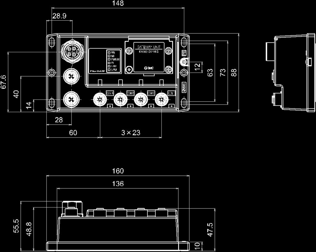
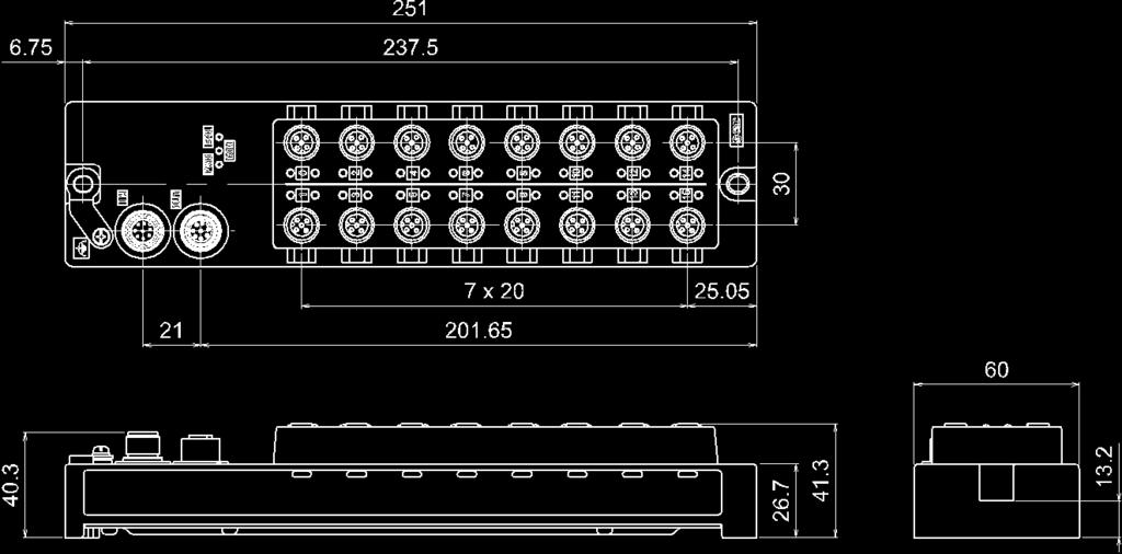
42 Dimensions
43 SI unit Model Indication and How to Order Summary of Product parts SI unit is combined with the manifold valve to communicate with GW unit. The EX9 series general output block can be connected with the SI unit to operate the solenoid valve or relays. No. Description Application 1 Branch connector (IN) Connector for branch cable (with M12 connector) from the GW unit. 1 2 Branch connector (OUT) Connector for branch cable (with M12 connector) to the next unit on the branch line. 1 3 Display and switch setting cover 4 Grounding terminal (FE) LED display to indicate the SI unit status. 2 Set the output points using the switches under the cover. Used for functional grounding. (M3 thread) (It is recommended to ground with resistance of 100 ohms or less) Accessories Hexagon socket head cap screw (M3 x 30): 2 pcs. Seal cap: 1 pc. (for M12 connector socket) Connects the SI unit and the valve manifold. For unused branch connector (OUT). 1: Refer to page 12 for wiring. 2: Refer to page 47 for display
44 Mounting and Installation Installation Refer to the drawing below. NOTE Tighten the screws while holding the SI unit and the supply/exhaust block assembly so that there is no gap between them. Tighten the screws with the tightening torque specified. (Tightening torque: 0.6 Nm) : Refer to the catalogue and the operation manuals for details of the installation of the solenoid valve and manifold
45 Ground connection NOTE Connect the FE terminal to ground

46 Output No. assignment : Output No. starts from 0, and will be assigned to the valves in order from the SI unit mounted side (D side). : Standard wiring on the manifold is for double-solenoid valves and output number starts A side and B side in that order. If the mounted valves are single solenoid valves, the output on B side will be empty. (See fig. a) : Special wiring specification with a mixed wiring of single solenoid and double solenoid can be specified with a wiring specification sheet. This makes it possible to specify the output numbers without empty outputs. (See fig. b)
47 Separate power supply It is possible to provide a separate power supply to the SI unit and valves using a Y branch connector. Separate connector pin layout M12, 4 pin, plug No. Description 1 24 VDC (For solenoid valves) 2 0 VDC (For solenoid valves) 3 Unused 4 Unused : Refer to page 76 for Y branch connector
48 LED Display and Settings LED display Display PWR COM PWR(V) LED is OFF Green LED is ON LED is OFF Green LED is ON LED is OFF Green LED is ON Meaning The power supply for input and control is OFF Power supply for input and control is ON Communication error between GW unit has occurred Communication between GW unit is normal Power supply for solenoid valve is OFF Power supply for solenoid valve is ON Switch setting Number of outputs Meaning output output : The default setting is
 Specifications 32 points (Internal switch for selecting 16 point or 32 point) Solenoid valve with")
 Operation, Storage: 35 to 85%RH (No condensation) No corrosive gas CE marking, UL(CSA), RoHS")
49 Specification Specifications Item Output type Number of outputs Connected load Short circuit protection Load current Internal current consumption Enclosure rating Body material Operating temperature range Operating humidity range Operating atmosphere Standard Weight System PNP (negative common) Specifications 32 points (Internal switch for selecting 16 point or 32 point) Solenoid valve with surge voltage suppressor of 24 VDC and 1.0 W or less (manufactured by SMC) Applicable Max power supply of GW unit 1.0 A, Max. external power supply 1.5 A 50 ma or less IP67 PBT Operation: -10 to 50 o C, Storage: -20 to 60 o C (No condensation or freezing) Operation, Storage: 35 to 85%RH (No condensation) No corrosive gas CE marking, UL(CSA), RoHS 200 g Gateway distribution system 2 (128 point) Applicable valve series Refer to the catalogue and the operation manuals for details of the specifications of the solenoid valve and manifold. Valve series SV series SY series VQC series S0700 series SV1000 SV2000 SV3000 SY3000 SY5000 SY7000 VQC1000, VQC2000, VQC4000 S0700 Power supply voltage for Solenoid valve Voltage drop may occur to the source voltage supplied via the SI unit to the valve due to the power consumption of the valves and the length of the branch cable. Refer to the guidelines of the Solenoid Valve Power Supply Voltage Drop below. : Y connector is also available depending on your usage
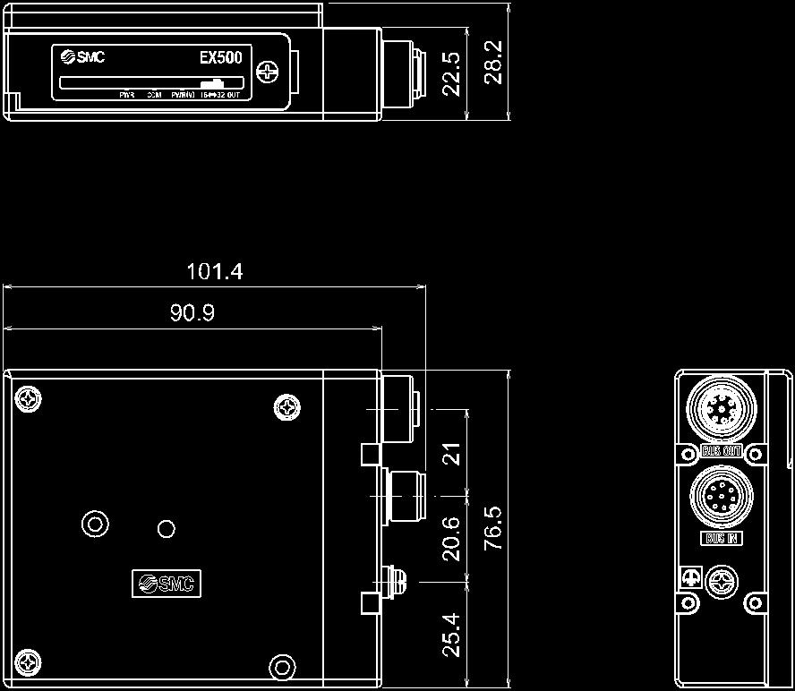
50 Dimensions
51 Input unit Model Indication and How to Order Summary of Product parts EX500-DXPA EX500-DXPB No. Description Application 1 Branch connector (IN) Connector for branch cable (with M12 connector) from the GW unit. 1 2 Branch connector (OUT) Connector for branch cable (with M12 connector) to the next unit on the branch line. 1 3 Display LED LED display to indicate the input status. 2 4 Sensor connector Connector for sensor. 1 5 Display LED Displays the sensor signal status. 2 6 Grounding terminal Used for functional grounding. (M3 thread) (It is recommended to ground with resistance of 100 ohms or less) 7 Grounding bracket Connect the mounting hole to the grounding terminal Accessories EX500-DXPA Seal cap: 1 pc. (for M12 connector socket) Seal cap: 16 pcs. (for M8 connector socket) EX500-DXPB Seal cap: 17 pc. (for M12 connector socket) 1: Refer to page 12 for wiring. 2: Refer to page 58 for display. For unused branch connector (OUT). Used for unused sensor connector. For unused branch connector (OUT)


52 Mounting and Installation Installation EX500-DXPA Install the product using 2 M4 screws x 20 mm or longer with a head ø8 minimum. EX500-DXPB Install the product using 2 M5 screws x 20 mm or longer with a head ø9 to ø
53 Wiring EX500-DXPA Branch wiring Connect the branch cable to the branch connector (IN/OUT). Refer to page 12 for wiring. Sensor wiring Connect the sensors to the sensor connectors. Pin layout of the sensor connector M8 connector (3 pin, socket) No. Description 1 Power supply (24 VDC) 3 Power supply (0 V) 4 Input NOTE Be sure to fit a seal cap on any unused connectors of the input block. IP67 is maintained by using the seal cap. (Tightening torque for M8: 0.05 Nm, M12: 0.1 Nm)

54 Sensor wiring example (PNP input) Correspondence between the input number and input The input number is assigned from 0 to 15 from the branch connector side
55 Ground connection The mounting hole at the branch connector side is connected to the ground terminal using the grounding bracket. NOTE Connect the FE terminal to ground
56 EX500-DXPB Branch wiring Connect the branch cable to the branch connector (IN/OUT). Refer to page 12 for wiring. Sensor wiring Connect the sensors to the sensor connectors. Pin layout of the sensor connector M12 connector (5 pin, socket) No. Description Even number 0 to 14 Odd number 1 to 15 1 Power supply (24 VDC) 2 (Input) 3 Power supply (0 V) 4. Input 5 FE
 Correspondence")


57 Sensor wiring example (PNP input) Correspondence between the input number and input The input number is assigned from 0 to 15 from the branch connector side
58 Ground connection The mounting hole at the branch connector side is connected to the ground terminal using the grounding bracket. NOTE Connect the FE terminal to ground
59 LED Display EX500-DXPA EX500-DXPB Display PWR COM ERR Display LED LED is OFF Green LED is ON LED is OFF Green LED is ON LED is OFF Red LED is ON LED is OFF Green LED is ON Meaning The power supply for input and control is OFF Power supply for input and control is ON Communication error between GW unit has occurred Communication between GW unit is normal Normal operation Short circuit detection Sensor signal input is OFF Sensor signal input is ON

 5 V or less/1.5 ma or less (at 24 VDC) Approx.")
60 Specification Specifications Item Input type PNP sensor input Number of inputs 16 Voltage for input equipment 24 VDC Specifications Current for input equipment Input ON voltage/input ON current Input OFF voltage/input OFF current Rated input current Internal current consumption Display Sensor connector Short circuit protection Enclosure rating Body material Operating temperature range Operating humidity range Operating atmosphere Standard Weight System Max. 1.3 A/unit (Total of 8 connectors of even number must be Max A, 8 connectors of odd number must be Max A) 11 V or more/typ.7 ma (at 24 VDC) 5 V or less/1.5 ma or less (at 24 VDC) Approx. 7 ma 200 ma or less (when the input signal is ON) Green LED (Lights when ON) EX500-DXPA: M8 connector (3 pin, socket) EX500-DXPB: M12 connector (5 pin, socket) Available IP67 PBT Operation: -10 to 50 o C, Storage: -20 to 60 o C (No condensation or freezing) Operation, Storage: 35 to 85%RH (No condensation) No corrosive gas CE mark, UL(CSA), RoHS EX500-DXPA: 250 g EX500-DXPB: 450 g Gateway distribution system 2 (128 point) Power supply voltage for input and control Voltage drop may occur to the source voltage supplied from the input unit to the sensor due to the connected unit, power consumption of the sensor or the length of the branch cable. Refer to the Guideline of the Voltage Drop of the Power Supply for Input and Control below
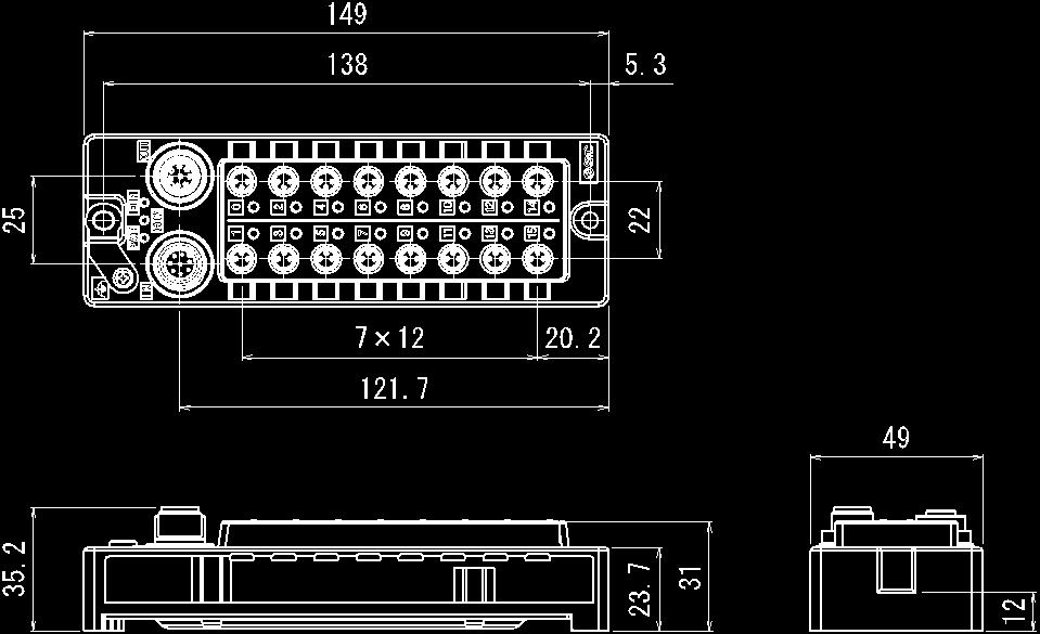
61 Dimensions EX500-DXPA EX500-DXPB
62 Interchangeability of system Mixed usage Gateway distribution system 2 (128 points) and gateway distribution system (64 points) EX500-GEN2, EX500-S103, EX500-DXP# are products for gateway distribution system 2 (128 points). Although it is possible to use with existing 64 point gateway distribution system, the operating condition must comply with the specifications of the 64 point gateway system. GW unit Gateway distribution system 2 (128 points) EX500-GEN2 EX500-GPN2 Gateway distribution system (64 points) EX500-GDN1 EX500-GPR1A SI unit Input unit Gateway distribution system 2 (128 points) EX500-S103 EX500-DXP# Gateway distribution system (64 points) EX500-S001 EX500-Q#01 EEX500-IB1-# Usable Usable :Same specifications of gateway distribution system (64 point) Usable :Same specifications of gateway distribution system (64 point) Usable Specifications of gateway distribution system (64 point) Item Number of inputs and outputs Number of occupied slave Rated current Branch cable length GW unit Input unit SI unit 64 input (16 input per branch) 64 output (16 output per branch) Specifications Max. 8 (Input unit: 1 pc./si unit: 1 pc. per branch) Power supply for input and control: 3.0 A Power supply for Solenoid valve: 3.0 A Max. 0.5 A/unit Max A/ unit Total length 10 m or less per branch
63 GW unit using SI unit for 64 point gateway distribution system and input unit. If EX500-GEN2 DIP switch No.3 is turned on, the unit starts up with the specifications of 64 point gateway distribution system and it is possible to use with 64 point gateway distribution system. : Diagnostic function of the gateway distribution system 2 (128 points) cannot be used. Method to connect GW unit to Rockwell Automation EtherNet/IP TM module (master) is shown below. Refer to the Operation Manual of the RSLogix5000 TM for the detailed operation. : This figure shows the display of Rockwell Automation software, RSLogix5000 TM. Select [EtherNet/IP TM module] in [I/O Configuration] folder, then select [New Module]. The [Select Module] screen is displayed. Select [ETHERNET-MODULE Generic Ethernet Module], then select [Create]
64 [Module Properties] screen is displayed. Perform each setting. (1) Name: Enter the required unit name. (2) Comm Format: Select the data format of Connection Parameters. (3) IP Address: Enter the IP address setting for the SI unit. (4) Assembly Instance: Perform setting as shown below. Item Decimal Common Format "Data-INT" "Data-SINT" Input Output Configuration (5) Size: Perform setting as shown below. Item Decimal Common Format "Data-INT" "Data-SINT" Input 8(words) 16(bytes) Output 8(words) 16(bytes) Configuration 0(words) 0 (bytes) (1) (4) (5) (2) (3)
65 I/O memory map for 64 points gateway distribution system mode Input data Offset (INT) Input data MSB LSB MSB LSB Meaning 0 IN15 IN14 IN13 IN12 IN11 IN10 IN9 IN8 IN7 IN6 IN5 IN4 IN3 IN2 IN1 IN0 COM A 1 IN31 IN30 IN29 IN28 IN27 IN26 IN25 IN24 IN23 IN22 IN21 IN20 IN19 IN18 IN17 IN16 COM B 2 IN47 IN46 IN45 IN44 IN43 IN42 IN41 IN40 IN39 IN38 IN37 IN36 IN35 IN34 IN33 IN32 COM C 3 IN63 IN62 IN61 IN60 IN59 IN58 IN57 IN56 IN55 IN54 IN53 IN52 IN51 IN50 IN49 IN48 COM D Reserved Reserved Reserved COM D COM C COM B COM A Port Status 0: Fixed to 0 < Port condition > Value Status 0 Connection port 1 Not connected Output data Offset (INT) Output data MSB LSB MSB LSB Meaning 0 OUT15 OUT14 OUT13 OUT12 OUT11 OUT10 OUT9 OUT8 OUT7 OUT6 OUT5 OUT4 OUT3 OUT2 OUT1 OUT0 COM A 1 OUT31 OUT30 OUT29 OUT28 OUT27 OUT26 OUT25 OUT24 OUT23 OUT22 OUT21 OUT20 OUT19 OUT18 OUT17 OUT16 COM B 2 OUT47 OUT46 OUT45 OUT44 OUT43 OUT42 OUT41 OUT40 OUT39 OUT38 OUT37 OUT36 OUT35 OUT34 OUT33 OUT32 COM C 3 OUT63 OUT62 OUT61 OUT60 OUT59 OUT58 OUT57 OUT56 OUT55 OUT54 OUT53 OUT52 OUT51 OUT50 OUT49 OUT48 COM D Reserved Reserved Reserved Reserved -: Unused
66 Troubleshooting Troubleshooting flow chart When any serial system failure occurs, perform the following trouble shooting. Serial system does not work correctly. Yes No Check the state of the GW unit. GW unit MS LED is OFF. Refer to fault No.1. GW unit MS LED is ON red. Refer to fault No.2. GW unit MS LED is flashing red. Refer to fault No. 3. GW unit MS LED is flashing green. Refer to fault No. 4. GW unit NS LED is OFF. Refer to fault No. 5. GW unit NS LED is ON red Refer to fault No. 6. GW unit NS LED is flashing red. Refer to fault No. 7. GW unit NS LED is flashing green. Refer to fault No. 8. GW unit PWR(V)_LED is Refer to fault No
67 The solenoid valve and output block do not operate correctly. SI unit PWR LED is OFF. Refer to fault No. 10. SI unit COM LED is OFF. Refer to fault No. 11. Check the status of the solenoid valves. Solenoid valves do not operate correctly, solenoid valve LED is OFF. Refer to fault No. 12. Solenoid valves do not operate correctly, solenoid valve LED is ON. Refer to fault No. 13. Input device data cannot be recognized. SI unit PWR LED is OFF Refer to fault No. 14. Input unit ERR LED is ON Refer to fault No. 15. Corresponding GW unit COM _LED is OFF. Refer to fault No. 16. Input unit LED does not turn ON. Refer to fault No. 15. Input unit LED and the input data do not match. Refer to fault No
68 Troubleshooting Fault No. 1 Fault Possible cause Investigation method Countermeasures GW unit MS LED is OFF. Wiring of the power supply for input and control is defective Check the power supply cable connections and check for broken wires. Tighten the power supply cable connection. (if there is a broken wire, replace the cable). Correct the power cable wiring layout. Incorrect power supply for input and control Check the supply voltage for input and control. Supply 24 VDC 10% to the power supply for control and inputs of the product. Fault No. 2 Fault Possible cause Investigation method Countermeasures GW unit MS LED is ON red Malfunction of the GW unit - Contact your sales representative. Fault No. 3 Fault Possible cause Investigation method Countermeasures GW unit MS LED is flashing red. Diagnostics error detected Check the meaning of diagnostic error. Solve the diagnostic error. Fault No. 4 Fault Possible cause Investigation method Countermeasures GW unit MS LED is flashing green. Parameter setting error - Contact your sales representative. Fault No. 5 Fault Possible cause Investigation method Countermeasures GW unit NS LED is OFF. No IP address Check the communication cable connections and check for broken wires. Tighten the communication cable connection. (if there is a broken wire, replace the cable) Wait for the IP address to be set by the DHCP server. Set the IP address using the DHCP server
69 Fault No. 6 Fault Possible cause Investigation method Countermeasures GW unit NS LED is ON red IP address has been duplicated Check that the IP address has not been duplicated on another slave unit. Set the IP address so that it is not duplicated. Fault No. 7 Fault Possible cause Investigation method Countermeasures Check the communication cable connections and check for broken wires. Tighten the communication cable connection. (if there is a broken wire, replace the cable) GW unit NS LED is flashing red. EtherNet/IP connection time out Check that the communication cable length is within the maximum specified length. Check that the recommended cable for EtherNet has been used. Check that the communication cable wiring is correct. Wire the communication cable according to the EtherNet wiring specifications. Check that there is no noise source or high voltage line around the EtherNet TM cables and power cables. Separate the communication and power supply cables away from noise sources. Fault No. 8 Fault Possible cause Investigation method Countermeasures GW unit NS LED is flashing green. Waiting for connection to be established. Check the address and communication setting. Check the communication cable connections and check for broken wires. Review the setting of the switch and address. Tighten the communication cable connection. (if there is a broken wire, replace the cable) Check if the PLC is operating normally. Review the setting of PLC. Fault No. 9 Fault Possible cause Investigation method Countermeasures GW unit PWR(V)_LED is OFF. Wiring of the solenoid valve power supply is defective. Check the power supply cable connections and check for broken wires. Tighten the power supply cable connection. (if there is a broken wire, replace the cable) Correct the power cable wiring layout. Solenoid valve power supply failure Check proper supply voltage of solenoid valve power supply. Power supply for solenoid valves: 24 VDC +10%/-5%
70 Fault No. 10 Fault Possible cause Investigation method Countermeasures SI unit PWR LED is OFF. Power supply for input and control: 24 VDC 10% Check the branch cable connections and check for broken wires. Tighten the branch cable connection. (if there is a broken wire, replace the cable) Fault No. 11 Fault Possible cause Investigation method Countermeasures SI unit COM LED is OFF. Communication failure of the branch port Check the branch cable connections and check for broken wires. Check the wiring length of the branch cable and check that the recommended cable is used. Tighten the branch cable connection. (if there is a broken wire, replace the cable) Review wiring Total length 20 m or less per branch Check that there is no high voltage cable or equipment that generates noise around the branch cable. Separate the branch cable away from noise sources. Fault No. 12 Fault Possible cause Investigation method Countermeasures Solenoid valves not operating correctly. Solenoid valve LED is OFF. Defective connection between the SI unit and solenoid valve manifold. Polarity of the solenoid valve and the SI unit output are not compatible. Check for any loose screws at the connection between the SI unit and the valve manifold. Check that the solenoid valve polarity specification and output polarity of the SI unit are compatible. Same as Investigation method. The solenoid valve polarity specification and output polarity of the SI unit are compatible. Solenoid valve failure Refer to the troubleshooting of the solenoid valve. Same as Investigation method
71 Fault No. 13 Fault Possible cause Investigation method Countermeasures Solenoid valves not operating correctly. Solenoid valve LED is ON. Solenoid valve failure Refer to the troubleshooting of the solenoid valve. Same as Investigation method. Fault No. 14 Fault Possible cause Investigation method Countermeasures Input unit PWR LED is OFF. Power supply for input and control: 24 VDC 10% Check the branch cable connections and check for broken wires. Tighten the branch cable connection. (if there is a broken wire, replace the cable) Fault No. 15 Fault Possible cause Investigation method Countermeasures Check the total current consumption of the input devices such as the sensor used. Ensure that the total current consumption is within the specified range of the input unit. Input unit ERR LED is ON Over current power supply for input and control Check the input devices used, and check the wiring to the input devices. Refer to the input device operation manual troubleshooting section, or contact the input device manufacturer. Resolve the short-circuit or over current. Same as Investigation method. Power supply short-circuit of the input devices used. Check the troubleshooting of input equipment Or, confirm with the manufacturer of the input equipment. Fault No. 16 Fault Possible cause Investigation method Countermeasures Check the branch cable connections and check for broken wires. Tighten the branch cable connection. (if there is a broken wire, replace the cable) Corresponding GW unit COM LED is OFF. Communication failure of the branch port Check the wiring length of the branch cable and check that the recommended cable is used. Revise the wiring length: Total length 20 m or less per branch Exclusive cables: EX500-AC -S P Check that there is no high voltage cable or equipment that generates noise around the branch cable. Separate the branch cable away from noise sources
72 Fault No. 17 Fault Possible cause Investigation method Countermeasures Polarity of the input unit and input device including sensor are not compatible. Check that the polarity of the input unit and the input device are compatible. Use an input device polarity compatible with the polarity of the input unit. Input unit display LED does not turn ON. Defective connection between the input unit and input device. Check the input device connection and wiring (pin layout) and check for broken wires. Tighten the cable connection. (Replace the cable if it is broken.) Rectify the wiring of the input device cable. Malfunction of input unit - Contact your sales representative. Fault No. 18 Fault Possible cause Investigation method Countermeasures Input unit display LED and the input data do not match. Communication failure of the branch port Malfunction of input unit Check the wiring length of the branch cable and check that the recommended cable is used. Check that there is no high voltage cable or equipment that generates noise around the branch cable. - Review wiring Total length 20 m or less per branch Separate the branch cable away from noise sources. Contact your sales representative

73 Accessories (1) Ethernet communication connector cable Cable O.D. Item Min. bending radius Specifications 6.7 mm 34 mm


74 Cable O.D. Item Nominal cross section Wire diameter (Including insulator) Min. bending radius Specifications 6.5 mm AWG mm 45.5 mm Pin No. Cable color: Signal 1 Yellow: TX+ 2 White: RX+ 3 Orange: TX- 4 Blue: RX- (2) Assembly type communication connector for Ethernet Applicable cable Cable O.D. Item Electric wire cross section (Twist line) Specifications 4.0 to 8.0 mm AWG26 to

 2 Green: 24 VDC (For input")
75 (3) Cable with 7/8 inch connector for power supply. Item Cable O.D. Nominal cross section Min. bending radius Specifications 10.7 mm AWG16 94 mm (when fixed) Pin No. Cable color: Signal 1 Red: 24 VDC (For solenoid valves) 2 Green: 24 VDC (For input and control) 3 White: 0 V (For input and control) 4 Black: 0 V (Solenoid valve)

 - 75")
76 (4) Branch cable with M12 connector Cable O.D. Item Min. bending radius Specifications ø6 mm 40 mm (When fixed)

 Bracket for mounting the input unit (EX500-DXPA,")
77 (5) Y branch connector Connector to provide a separate power supply to SI unit valve. (6) DIN rail bracket (2 pcs.) Bracket for mounting the input unit (EX500-DXPA, EX500-DXPB) to DIN rail. Example: EX500-DXPA
 Seal cap Mount the seal cap in the unused ports of the GW unit and input unit. IP65/67 is satisfied by using the seal cap properly. (The seal cap is provided with each product.")
78 (7) Marker (1 sheet, 88 pcs.) The signal name of the input device and unit address can be written on the marker, and can be installed to each unit. (8) Seal cap Mount the seal cap in the unused ports of the GW unit and input unit. IP65/67 is satisfied by using the seal cap properly. (The seal cap is provided with each product.) NOTE Tighten the seal caps to the tightening torque specified. (For M8: 0.05 Nm, M12: 0.1 Nm)
Series IZH10. Handheld Electrostatic Meter. How to Order. Accessories and Option / Part Number for Individual Parts.
 Peak G 15min Handheld Electrostatic Meter Series IZH10 How to Order IZH10 Option Nil H None High-voltage measuring handle Accessories and Option / Part Number for Individual Parts The ground wire and soft
High Pressure E/P Regulator. ITVH Series
 Doc. No. DIQ-69200-OM002-A P R O D U C T N A M E High Pressure E/P Regulator MODEL/ Series/ Product Number ITVH Series Install and operate the product only after reading the Operation Manual carefully
EtherNet/IP TM SI unit
 EX##-####### PRODUCT NAME EtherNet/IP TM SI unit MODEL / Series / Product Number UIUSP-SEN#-DUO02979 Contents Safety Instructions 2 How to Order 7 Summary of Product elements 8 Installation and Cabling
SI unit for EtherNet/IP TM EX250-SEN1
 PRODUCT NAME SI unit for EtherNet/IP TM MODEL / Series / Product Number EX250-SEN1 Table of Contents Safety Instructions 2 Product Summary 7 Definition and terminology 8 Model Indication and How to Order
Fieldbus system EtherNet/IP TM compatible SI Unit
 PRODUCT NAME Fieldbus system EtherNet/IP TM compatible SI Unit MODEL / Series / Product Number EX600-SEN3/4 EX600-ED# Table of Contents Safety Instructions 2 System Outline 8 Definition and terminology
Operation Manual. Fieldbus system EX510-GDN1. DeviceNet Compatible GW unit
 Fieldbus system DeviceNet Compatible GW unit Operation Manual EX50-GDN URL http://www.smcworld.com Akihabara UDX 5F, --, Sotokanda, Chiyoda-ku, Tokyo 0-00, JAPAN Phone: +8-507-89 Fax: +8-598-56 Note: Specifications
SI unit for IO-Link device
 PRODUCT NAME SI unit for IO-Link device MODEL / Series / Product Number EX260-SIL1-X207 EX260-SIL1-X210 EX260-SIL3-X207 Table of Contents Safety Instructions 2 Model Numbers 8 Summary of Product 9 Summary
SI unit for IO-Link device
 PRODUCT NAME SI unit for IO-Link device MODEL / Series / Product Number EX260-SIL1-X207 EX260-SIL1-X210 EX260-SIL3-X207 Table of Contents Safety Instructions 2 Model Indication and How to Order 8 Summary
Operation Manual. Fieldbus system EX510-GPR1. PROFIBUS DP Compatible GW unit
 Fieldbus system PROFIBUS DP Compatible GW unit Operation Manual EX50-GPR URL http://www.smcworld.com Akihabara UDX 5F, --, Sotokanda, Chiyoda-ku, Tokyo 0-00, JAPAN Phone: +8 3-507-89 Fax: +8 3-598-536
Fieldbus system Analog unit
 PRODUCT NAME Fieldbus system Analog unit MODEL / Series / Product Number EX600-AXA EX600-AYA EX600-AMB Table of Contents Safety Instructions 3 System Outline 9 Assembly 10 Mounting and Installation 12
Fieldbus system EtherCAT compatible SI unit
 PRODUCT NAME Fieldbus system EtherCAT compatible SI unit MODEL / Series/ Product Number EX600-SEC# EX600-ED# Table of Contents Safety Instructions 2 System Outline 8 Definition and terminology 9 Assembly
Ethernet ITV Modbus TCP
 IN19850 PRODUCT NAME Ethernet ITV Modbus TCP MODEL / Series / Product Number ITVXXXX-SMB-XX-DUQ00833-XXXX - 1 - Contents 1. Safety Instructions...- 4-2. About this Manual...- 9-2.1. Purpose...- 9-3. Terminology...
OPERATION MANUAL E/P REGULATOR MODEL NAME. Series. For DeviceNet TM CONTENTS. Contents. Safety Instructions. Precautions for Handling P3-4
 OPERATION MANUAL E/P REGULATOR MODEL NAME ITV*0*0 *0*0-DE**** series Series For DeviceNet TM CONTENTS TM Contents Safety Instructions P1 P2 Precautions for Handling P3-4 Wiring and LED display P5-6 Mounting
Fieldbus system (SI unit compatible CompoNet)
") PRODUCT NAME Fieldbus system (SI unit compatible CompoNet) MODEL / Series / Product Number EX12#-SCM# Table of Contents Safety Instructions 2 Product Summary 7 Model Identification and How to Order 7 Names
PRODUCT NAME Fieldbus system (SI unit compatible CompoNet) MODEL / Series / Product Number EX12#-SCM# Table of Contents Safety Instructions 2 Product Summary 7 Model Identification and How to Order 7 Names
JXC-W1 (JXC#3 Series)
") Product Name Controller Setting Software (For 4-axis Step Motor Controller) MODEL/ Series/ Product Number JXC-W1 (JXC#3 Series) Contents 1. Safety Instructions... 3 2. Product Specifications... 5 2.1 Features
Product Name Controller Setting Software (For 4-axis Step Motor Controller) MODEL/ Series/ Product Number JXC-W1 (JXC#3 Series) Contents 1. Safety Instructions... 3 2. Product Specifications... 5 2.1 Features
Product Name. Controller Setting Software (For 3-axis Step Motor Controller) MODEL/ Series/ Product Number. JXC#2 Series
 MODEL/ Series/ Product Number. JXC#2 Series") No.JXC -OMU0024 Product Name Controller Setting Software (For 3-axis Step Motor Controller) MODEL/ Series/ Product Number JXC#2 Series CD-ROM included JXC-MA1 Controller Setting Software for JXC#2 Series
No.JXC -OMU0024 Product Name Controller Setting Software (For 3-axis Step Motor Controller) MODEL/ Series/ Product Number JXC#2 Series CD-ROM included JXC-MA1 Controller Setting Software for JXC#2 Series
Fieldbus system PROFIBUS DP compatible SI unit
 PRODUCT NAME Fieldbus system PROFIBUS DP compatible SI unit MODEL / Series / Product Number EX600-SPR#A EX600-ED# Table of Contents Safety Instructions 3 System Outline 9 Definition and terminology 10
No.EX##-OMN0032. Fieldbus system EtherNet/IP TM compatible SI unit PRODUCT NAME. EX600-SEN# EX600-ED# MODEL/ Series
 Fieldbus system EtherNet/IP TM compatible SI unit PRODUCT NAME EX600-SEN# EX600-ED# MODEL/ Series Table of Contents Safety Instructions 3 System Outline 9 Definition and terminology 10 Assembly 12 Mounting
No.EX##-OMN0036. Fieldbus system Digital unit PRODUCT NAME. EX600-DX## EX600-DY## EX600-DM## MODEL/ Series
 Fieldbus system Digital unit PRODUCT NAME EX600-DX## EX600-DY## EX600-DM## MODEL/ Series Table of Contents Safety Instructions 3 System Outline 9 Assembly 10 Mounting and Installation 12 Installation 12
Fieldbus system EtherNet/IP TM compatible SI unit
 PRODUCT NAME Fieldbus system EtherNet/IP TM compatible SI unit MODEL / Series / Product Number EX600-SEN# EX600-ED# Table of Contents Safety Instructions 3 System Outline 9 Definition and terminology 10
No.EX##-OMN0028. Fieldbus system PROFIBUS DP compatible SI unit PRODUCT NAME. EX600-SPR#A EX600-ED# MODEL/ Series
 Fieldbus system PROFIBUS DP compatible SI unit PRODUCT NAME EX600-SPR#A EX600-ED# MODEL/ Series Table of Contents Safety Instructions 3 System Outline 9 Definition and terminology 10 Assembly 12 Mounting
No.EX##-OMN0030-A. Fieldbus system DeviceNet TM compatible SI unit PRODUCT NAME. EX600-SDN#A EX600-ED# MODEL/ Series
 Fieldbus system DeviceNet TM compatible SI unit PRODUCT NAME EX600-SDN#A EX600-ED# MODEL/ Series Table of Contents Safety Instructions 3 System Outline 9 Definition and terminology 10 Assembly 12 Mounting
No.EX##-OMN0034. Fieldbus system CC-Link compatible SI unit PRODUCT NAME. EX600-SMJ# EX600-ED# MODEL/ Series
 Fieldbus system CC-Link compatible SI unit PRODUCT NAME EX600-SMJ# EX600-ED# MODEL/ Series Table of Contents Safety Instructions 2 System Outline 8 Definition and terminology 9 Assembly 11 Basic precautions
Controller setting kit Software (ACT Controller)
") No.JXC -OMU0010 PRODUCT NAME Controller setting kit Software (ACT Controller) MODEL/ Series JXC-W2 series Contents 1. Safety Instructions... 2 2. Product Outline... 4 3. Operation explanation... 5 3.1
No.JXC -OMU0010 PRODUCT NAME Controller setting kit Software (ACT Controller) MODEL/ Series JXC-W2 series Contents 1. Safety Instructions... 2 2. Product Outline... 4 3. Operation explanation... 5 3.1
Flow Monitor PF2A20# PF2W20# PF2D20#
 PRODUCT NAME Flow Monitor MODEL / Series / Product Number PF2A20# PF2W20# PF2D20# Table of Contents Safety Instructions 2 Model Indication and How to Order 9 Summary of Product parts 12 Definition and
SMC Wireless System. EX600-WEN# (Wireless master) EX600-WSV# (Wireless slave)
 EX600-WSV# (Wireless slave)") PRODUCT NAME SMC Wireless System MODEL / Series / Product Number EX600-WEN# (Wireless master) EX600-WSV# (Wireless slave) Contents Safety Instructions 2 SMC Wireless System Features 8 SMC Wireless System
PRODUCT NAME SMC Wireless System MODEL / Series / Product Number EX600-WEN# (Wireless master) EX600-WSV# (Wireless slave) Contents Safety Instructions 2 SMC Wireless System Features 8 SMC Wireless System
Electrostatic Sensor Monitor IZE11
 PRODUCT NAME Electrostatic Sensor Monitor MODEL/ Series IZE11 Table of Contents Safety Instructions 2 Model Identification and How to Order 7 Summary of Product parts 8 Mounting and Installation 10 Installation
No.EX##-OMJ0001. SI unit for ControlNet PRODUCT NAME. EX250-SCN1 Series MODE/ Series
 No.EX##-OMJ0001 SI unit for ControlNet PRODUCT NAME EX250-SCN1 Series MODE/ Series Table of Contents Safety Instructions 2 Model no. of product and how to order 6 Contents of package 6 Description and
Digital Gap Checker. ON: Placed. Workpiece. Large gap. Workpiece. Workpiece. Small gap. Detection surface Detection nozzle. Air
 -Color Display Digital Gap Checker. to.5 mm (Displayable/Settable range: to ) G type Rated detection distance range ON: Placed H type Rated detection distance range Workpiece.5 to. mm (Displayable/Settable
Multi Channel Pressure Sensor Controller PSE200
 PRODUCT NAME Multi Channel Pressure Sensor Controller MODEL / Series / Product Number PSE200 Table of Contents Safety Instructions 2 Model Indication and How to Order 8 Summary of Product parts 9 Definition
Digital Pressure Switch
 PRODUCT NAME Digital Pressure Switch MODEL / Series / Product Number ZSE20(F) ISE20 Table of Contents Safety Instructions 2 Model Indication and How to Order 8 Summary of Product parts 10 Definition and
SI unit for DeviceNet TM. EX180-SDN3/4/5/6 Series
 PRODUCT NAME SI unit for DeviceNet TM MODEL / Series / Product Number EX180-SDN3/4/5/6 Series Contents Safety Instructions 2 How to Order 7 Summary of Product Parts 8 Installation and Cabling 9 General
Digital Pressure Switch
 PRODUCT NAME Digital Pressure Switch MODEL / Series / Product Number ZSE20A(F) ISE20A Table of Contents Safety Instructions 2 Model Indication and How to Order 8 Summary of Product parts 10 Definition
Fieldbus system (DeviceNet compliant)
") PRODUCT NAME Fieldbus system (DeviceNet compliant) MODEL / Series / Product Number EX510-GDN1 Series Table of Contents Safety Instructions 3 Model Indication and How to Order 8 Summary of Product Parts
PRODUCT NAME Fieldbus system (DeviceNet compliant) MODEL / Series / Product Number EX510-GDN1 Series Table of Contents Safety Instructions 3 Model Indication and How to Order 8 Summary of Product Parts
HITACHI. EH-150 series PLC EH-RTD8 Resistance Temperature Detective input module Instruction manual. Safety precautions
 HITACHI EH-150 series PLC Resistance Temperature Detective input module Instruction manual Thank you for purchasing a Hitachi Programmable Logic Controller. To operate it safely, please read this instruction
Reduced wiring system. PROFIBUS-DP Compatible GW unit. Operation Manual EX510-GPR1. URLhttp://www.smcworld.com
 Reduced wiring system PROFIBUS-DP Compatible GW unit Operation Manual EX510-GPR1 URLhttp://www.smcworld.com 1 Table of Contents Thank you for purchasing the SMC reduced wiring system EX510 series. Please
Fieldbus System (For Input/Output)
") Integrated input-output type Fieldbus System (For Input/Output) EX245 Series AIDA* specifications compliant Push Pull s EX123/124/126 EX600 Push Pull s EX500 IP65 One-touch installation and removal Reduced
Integrated input-output type Fieldbus System (For Input/Output) EX245 Series AIDA* specifications compliant Push Pull s EX123/124/126 EX600 Push Pull s EX500 IP65 One-touch installation and removal Reduced
H Series PLC. ! : Indicates Compulsion. EH-150 Analog input module EH-AXH8M Instruction manual. Safety precautions DANGER CAUTION COMPULSION
 H Series PLC EH-150 Analog input module EH-AXH8M Instruction manual Thank you for purchasing a Hitachi Programmable Logic Controller. To operate it safely, please read this instruction manual and all the
Doc. No.: EX**-OMC0024. Instruction Manual. SI Unit / DI Unit EX240-SDN2 EX240-IE1 SMC CORPORATION
 Doc. No.: EX**-OMC00 Instruction Manual SI Unit / DI Unit EX0-SDN EX0-IE SMC CORPORATION SAFETY INSTRUCTIONS (Read carefully before use.) Thoroughly read this technical instruction manual and related manuals
EX120/121/122 Series Some protocols are not CE-compliant.
 Output type for solenoid valves (For Output) EX120/121/122 Series Compatible Protocols CompoBus/S NKE Corp.: Fieldbus H System Made to Order Small unit compatible with a maximum of 16 outputs Compatible
Actuator Position Sensor. D-MP# series
 PRODUCT NAME Actuator Position Sensor MODEL / Series / Product Number D-MP# series Table of Contents Safety Instructions 2 Model Indication and How to Order 8 Summary of Product parts 8 Mounting and Installation
CJ Series EtherNet/IP TM Connection Guide. SMC Corporation Solenoid Valve (SI Unit EX600-SEN#) P657-E1-01
 P657-E1-01") CJ Series EtherNet/IP TM Connection Guide SMC Corporation Solenoid Valve (SI Unit EX600-SEN#) P657-E1-01 About Intellectual Property Rights and Trademarks Microsoft product screen shots reprinted with
CJ Series EtherNet/IP TM Connection Guide SMC Corporation Solenoid Valve (SI Unit EX600-SEN#) P657-E1-01 About Intellectual Property Rights and Trademarks Microsoft product screen shots reprinted with
Pressure Sensor Controller PSE300
 PRODUCT NAME Pressure Sensor Controller MODEL / Series / Product Number PSE300 Table of Contents Safety Instructions 2 Model Indication and how to order 7 Summary of Product parts 8 Mounting and Installation
Operating instructions. Switching amplifier DN0210 DN / / 2015
 Operating instructions Switching amplifier DN0210 DN0220 UK 80011079 / 00 01 / 2015 Contents 1 Preliminary note...4 1.1 Symbols used...4 1.2 Warning signs used...4 2 Safety instructions...5 2.1 General...5
Conductive Level Controller
 Conductive Level Controller 61F-D21T-V1 Ideal for level control for industrial facilities and equipment. Outputs can be set to self-hold at ON or OFF using self-holding circuits. Sensitivity adjustment
Fieldbus system PROFIBUS DP compatible PRODUCT NAME EX600-SPR* EX600-DX* EX600-DY* EX600-AX* EX600-ED*
 Fieldbus system PROFIBUS DP compatible PRODUCT NAME EX600-SPR* EX600-DX* EX600-DY* EX600-AX* EX600-ED* MODEL/ Series Table of Contents Safety Instructions 2 Product Outline 9 Assembly 12 Mounting and Installation
Instruction Manual. Reduced wiring system EtherNet/IP Compatible SI Unit EX250-SEN1. URL
 Reduced wiring system EtherNet/IP Compatible SI Unit Instruction Manual EX-SEN URL http:// www.smcworld.com Specifications are subject to change without prior notice and any obligation on the part of the
No.EX##-OML0007. Fieldbus system DeviceNet TM compatible PRODUCT NAME. EX600-SDN* EX600 DX* EX600 DY* EX600 AX* MODEL/ Series
 Fieldbus system DeviceNet TM compatible PRODUCT NAME EX600-SDN* EX600 DX* EX600 DY* EX600 AX* MODEL/ Series Table of Contents Safety Instructions 2 Product Outline 9 Assembly 11 Mounting and Installation
TOP - 1. Instruction Manual. Version 1.0 Produced in Jan. 2004
 Version 1.0 Produced in Jan. 2004 Instruction Manual LCD monitor IV-08MP Thank you for purchasing the SHARP IV-08MP LCD monitor. Read this introductory instruction manual carefully to thoroughly familiarize
Preface. Copyright 1997, Digital Electronics Corporation MS-DOS and Windows 95 are registered trademarks of the Microsoft Corporation.
 Preface Thank you for purchasing the Profibus DP unit, hereafter referred to as the Profibus unit. This unit is intended for use with the Digital Electronics Corporation s GP-470/570/675/870 series touch
Operating instructions AS-i SmartLine module AC3200 AC /00 06/2016
 Operating instructions AS-i SmartLine module AC3200 AC3201 80237876/00 06/2016 Contents 1 Preliminary note...3 1.1 Symbols used...3 1.2 Warnings used...3 2 Safety instructions...3 2.1 General...3 2.2 Target
Operating instructions. Speed monitor D / / 2014
 Operating instructions Speed monitor D200 80005257 / 00 05 / 2014 Contents 1 Preliminary note...4 1.1 Symbols used...4 1.2 Warning signs used...4 2 Safety instructions...5 2.1 General...5 2.2 Target group...5
Making Hazardous Operations Safe and Productive
 NEW Safety Guard Switching Unit G9SX-GS Making Hazardous Operations Safe and Productive Making Hazardous Operations Safe and Productive This new addition to the model of Flexible Safety Unit G9SX series
MT8050iE series. Installation Instruction (1) (2)
 (2)") MT8050iE series 3 Installation Instructions Installation Instruction Secure the operator panel in position, using all the fastening holes and the provided brackets and screws: (A) 1 Installation and Startup
MT8050iE series 3 Installation Instructions Installation Instruction Secure the operator panel in position, using all the fastening holes and the provided brackets and screws: (A) 1 Installation and Startup
0.01kV (0 to ±0.99 kv)
") Handheld Electrostatic Meter 10 Series Easy-to-use handheld electrostatic meter Rated charge amount range: ±20.0 kv Minimum display unit: 0.1kV (±1.0 to ±20.0 kv) 0.01kV (0 to ±0.99 kv) RoHS IZE Check
Handheld Electrostatic Meter 10 Series Easy-to-use handheld electrostatic meter Rated charge amount range: ±20.0 kv Minimum display unit: 0.1kV (±1.0 to ±20.0 kv) 0.01kV (0 to ±0.99 kv) RoHS IZE Check
SmartRail I/O Ethernet Base HE599ETX300
 MAN--EN Specifications / Installation SmartRail I/O Ethernet Base HE599ETX INTRODUCTION SmartRail I/O is a real-time, modular I/O system that supports a variety of Ethernet and Fieldbus Communication architectures.
B63/ NS MS. EtherNet/IP LINK
 3 609 929 B63/ IMenip 2008-09 NS MS EtherNet/IP LINK 3 609 929 B63/2008-09 IMenip Bosch Rexroth AG 15/76 Table of Contents About this document................. 16 General safety instructions............
PLC-24V10AL(-PT/-TH) Quick Start Manual (Rev.1.10)
 Quick Start Manual (Rev.1.10)") TEC (Peltier) Controller PLC-24V10AL(-PT/-TH) Quick Start Manual (Rev.1.10) Thank you for purchasing the TEC (Peltier) Controller PLC-24V10AL. Read these operating instructions carefully to ensure effective
TEC (Peltier) Controller PLC-24V10AL(-PT/-TH) Quick Start Manual (Rev.1.10) Thank you for purchasing the TEC (Peltier) Controller PLC-24V10AL. Read these operating instructions carefully to ensure effective
The following symbols are used to show dangerous operation or handling. Make sure you understand them before reading the guide.
 Safety Instructions Before use Thank you very much for purchasing this product. This product is an interface box called "Connection & Control Box" for EPSON short throw projectors. For your safety, read
panasonic.net/id/pidsx/global CCD The sensor can be used for various applications with its binary data output with four different sensing modes.
 1123 PHOTO PHOTO PARTICUR Type Edge Sensor SERIES Related Information General terms and conditions... F-3 About laser beam... P.1593~ guide... P.1021~ General precautions... P.1595 Conforming to FDA regulations
99 Washington Street Melrose, MA Phone Toll Free Visit us at
 99 Washington Street Melrose, MA 02176 Phone 781-665-1400 Toll Free 1-800-517-8431 Visit us at www.testequipmentdepot.com Table of Contents 1. General Safety Requirements... 1 2. Safety Terms and Symbols...
V E1B Snap-in I/O Module
 V200-18-E1B Snap-in I/O Module The V200-18-E1B plugs directly into the back of compatible Unitronics OPLCs, creating a selfcontained PLC unit with a local I/O configuration. Features 16 isolated digital
Thread length (overall length) material
 material") Cylindrical Proximity Sensor for Mobile Usage Designed and tested to keep your machines moving IP69k tested and certified for highest water resistance e1 type approval (according to automotive directive
Cylindrical Proximity Sensor for Mobile Usage Designed and tested to keep your machines moving IP69k tested and certified for highest water resistance e1 type approval (according to automotive directive
Installation Manual INTELLIGENT SERVER. Model name: BMS-LSV6UL
 Model name: BMS-LSV6UL INTELLIGENT SERVER Thank you very much for purchasing this TOSHIBA INTELLIGENT SERVER. Please read this manual carefully beforehand for proper installation of the SERVER. NOTE This
GENERAL PRECAUTIONS GENERAL DESCRIPTION... 6
 Cat.No I173E-EN-01 RX Inverter Expansion I/O Board 3G3AX-EIO21-ROE USER S MANUAL GENERAL PRECAUTIONS... 3 1 GENERAL DESCRIPTION... 6 2 INSTALLATION PROCEDURE... 7 2.1 INSTALLING THE EXPANSION I/O BOARD...
Fieldbus System. New. New. Series EX260 IP67. Drives up to 32 solenoids. Daisy-chain wiring communication. Compact 28mm
 Fieldbus System (Output device for driving port solenoid valves) Compact 8mm (Actual size) Space-saving Installation Daisy-chain wiring communication New IP67 For units with D-sub connector, and when connected
Carbon Monoxide Sensor - ModBus
 Introduction The CO Sensor uses an electrochemical sensor to monitor CO level in a range of 0 to 500 ppm and communicates via an RS-485 network configured for ModBus protocol. Before Installation Read
G9SX-GS. Safety Guard Switching Unit. A Safety Measure for Hazardous Operations That Does Not Lower Productivity. Auto Switching Function
 Safety Guard Switching Unit CSM DS_E_6_1 A Safety Measure for Hazardous Operations That Does Not Lower Productivity Two functions support two types of application: Auto switching: For applications where
28mm. Fieldbus System. EX260 Series. IP67 For units with D-sub connector, and when connected to S0700 manifolds, it is IP40. Drives up to 32 solenoids
 Fieldbus System EX60 Series (Output device for driving port solenoid valves) Compact 8mm Space-saving Installation RoHS IP67 For units with D-sub connector, and when connected to S0700 manifolds, it is
PC Wiring System. e-con type is newly added! One-touch connection reduces wiring labor. Series PCW
 PC Wiring System Series PCW econ type is newly added! Onetouch connection reduces wiring labor. Branch unit offers commonality Branch unit separates each manufacturer s point Input/Output (I/O) into point
External level devices for conductive point level switch
 SENSORS FOR FOOD AND BIOPHARMA. Product Information VNV-2, ZNV-2 CONTROLS External level devices for conductive point level switch Application/Specified usage Point level detection of aqueous, conductive
DPDT Basic Switch for Two Independent Circuit Control
 Special-purpose Basic Switch DZ CSM_DZ_DS_E DPDT Basic Switch for Two Independent Circuit Control Ideal for switching the circuits operating on two different voltages, and for controlling two independent
: EX##-OMC0024-A. Instruction Manual. SI Unit / DI Unit EX240-SDN2 EX240-IE1
 : EX##-OMC00-A Instruction Manual SI Unit / DI Unit EX0-SDN EX0-IE SAFETY INSTRUCTIONS (Read carefully before use.) Thoroughly read this technical instruction manual and related manuals mentioned here
Fan Type Ionizer. IZF10R Series
 PRODUCT NAME Fan Type Ionizer MODEL / Series / Product Number IZF10R Series Contents Safety Instructions... 2 1. How to Order... 7 1-1. Product... 7 1-2. Accessories... 7 1-3. Maintenance parts... 8 1-4.
Ethernet/IP Module. User Manual. Contents
 User Manual Contents 1 Important User Information... 2 2 Installation... 3 3 Connection... 4 4 Device Configuration... 5 5 Operation... 8 6 Packet Structures... 9 7 Network Design... 18 8 Specifications...
Table of Contents. 3.1 Front/Rear Panel and User Interface Front Panel Rear Panel User Interface...
 General Warranty OWON warrants that the product will be free from defects in materials and workmanship for a period of 2 years (1 year for accessories) from the date of purchase of the product by the original
The following symbols are used to show dangerous operation or handling. Make sure you understand them before reading the guide.
 Safety Instructions Before use Thank you very much for purchasing this product. This product is an interface box called "Connection & Control Box" for EPSON short throw projectors. For your safety, read
4 Axis Step Motor Controller
 INFORMATION 4 Axis Step Motor Controller (Parallel I/O) RoHS V 4 axis synchronous control V Linear/circular interpolation Linear interpolation 50 Circular interpolation 50 Target position Axis 0 Target
Model Number Structure
 Digital Panel Meter CSM DS_E_2_1 Easy-to-use, w-cost Digital Panel Meter that Accepts AC Input Compact DIN-size (96 x 48 (W x H)) body. Mounting thickness of only 3.5 mm required. ghly visible display
V E2B Snap-in I/O Module
 V200-18-E2B Snap-in I/O Module The V200-18-E2B plugs directly into the back of compatible Unitronics OPLCs, creating a selfcontained PLC unit with a local I/O configuration. Features 16 isolated digital
COMFORT CONTROL CENTER SERVICE INSTRUCTIONS
 USA SERVICE OFFICE Dometic Corporation 2320 Industrial Parkway Elkhart, IN 46516 574-294-2511 CANADA Dometic Corporation 46 Zatonski, Unit 3 Brantford, ON N3T 5L8 CANADA 519-720-9578 For Service Center
Cable specifications PVC
 IO-Link Proximity Sensor (Spatter-resistant Models) EEQ-@-IL@ IO-Link Makes Sensor Level Information Visible and Solves the hree Major Issues at Manufacturing Sites! A Proximity Sensor hat Can Be Used
IO-AO6X I/O Expansion Module 6 Isolated Analog Outputs
 IO-AO6X I/O Expansion Module 6 Isolated Analog Outputs The IO-AO6X is an I/O Expansion Module that can be used in conjunction with specific Unitronics OPLC controllers. The module offers 6 12-bit isolated
IO-DI8-TO8, IO-DI8-TO8-L I/O Expansion Modules 8 Inputs, 8 Outputs
 IO-DI8-TO8, IO-DI8-TO8-L I/O Expansion Modules 8 Inputs, 8 Outputs The IO-DI8-TO8 and IO-DI8-TO8-L are I/O expansion modules that can be used in conjunction with specific Unitronics OPLC controllers. The
Appearance Size (mm) Power supply voltage Model (W H D) 100 to 240 VAC K3SC to 240 VAC
 Power supply voltage Model (W H D) 100 to 240 VAC K3SC to 240 VAC") Interface Converter A compact converter that allows communications between RS-C/USB and RS-/8 devices. Ideal for industrial applications. Allows communications between RS-C/USB (Universal Serial Bus) and
Interface Converter A compact converter that allows communications between RS-C/USB and RS-/8 devices. Ideal for industrial applications. Allows communications between RS-C/USB (Universal Serial Bus) and
E2A. Ordering Information. Cylindrical Proximity Sensor. Safe Mounting with Greater Sensing Distance. E2A Cylindrical Proximity Sensor 1
 Cylindrical Proximity Sensor E2A Safe Mounting with Greater Sensing Distance Ensures a sensing distance approximately 1. to 2 times larger than that of any conventional OMRON Sensor. Problems such as the
Model NPN output PNP output Standard. configuration
 Slot-type Photomicrosensor (Non-modulated) *1 EE-SX4/6 CSM_EE-SX4_6_DS_E 1 Global Standard Slot-type photomicrosensors with 0- to 100-mA direct switching capacity. Series includes models that enable switching
Analog Input Installation Manual
 Analog Input Installation Manual August 2011 Part Number: 144-23917 Copyright 2011 Magnetek 1. Preface and Safety Magnetek manufactures products used as components in a wide variety of industrial systems
COMMUNICATION CONVERTER FOR PROFIBUS
 INSTRUCTION MANUAL COMMUNICATION CONVERTER FOR PROFIBUS IFP-100 No.IFP11E3 2012.01 Preface Thank you for purchasing our IFP-100, Communication Converter for PROFIBUS. This manual contains instructions
Option 2. Nil. Note 1) Option 1. Note With waterproof seal and mounting screw. With waterproof seal and mounting screw. 48 conversion adapter
 Option 1. Note With waterproof seal and mounting screw. With waterproof seal and mounting screw. 48 conversion adapter") Series 0-PSE00 RoHS Remote Type Multi-Channel Digital Pressure Sensor Controller How to Order Clean series 0 PSE0 0 M Input/Output specifications 0 NPN 5 outputs + Auto shift input PNP 5 outputs + Auto
Series 0-PSE00 RoHS Remote Type Multi-Channel Digital Pressure Sensor Controller How to Order Clean series 0 PSE0 0 M Input/Output specifications 0 NPN 5 outputs + Auto shift input PNP 5 outputs + Auto
Line reactors SINAMICS. SINAMICS G130 Line reactors. Safety information 1. General. Mechanical installation 3. Electrical installation
 Safety information 1 General 2 SINAMICS SINAMICS G130 Mechanical installation 3 Electrical installation 4 Technical specifications 5 Operating Instructions Control version V4.7 04/2014 A5E00331462A Legal
Handheld Reader Writer
 Handheld Reader Writer CH1D-V2 A Compact Lightweight Easy-to-use Pen-type Reader Writer. Connects directly to a personal computer or PLC via RS-232C. The Reader Writer s protective construction is IP63
Analog Monitor Installation Manual
 Analog Monitor Installation Manual Part Number: 144-23919 Copyright 2011 Magnetek 1. Preface and Safety Magnetek manufactures products used as components in a wide variety of industrial systems and equipment.
PTB 01 ATEX Example / Beispiel / Exemple. Type Operating Instructions
 Device with II 2G EX i approval Geräte mit II 2G EX i Zulassung Appareils avec mode de protection II 2G EX i Example / Beispiel / Exemple Type 6106 Operating Instructions Bedienungsanleitung Manuel d utilisation
Installing and Configuring Rialto Analytic Appliances
 Installing and Configuring Rialto Analytic Appliances Important Safety Information This manual provides installation and operation information and precautions for the use of this camera. Incorrect installation
RS232C/RS485 Data can be easily monitored by LAN
 KS SIGNAL CVERTER (AKS) RSC/RS8 Data can be easily monitored by LAN KS SIGNAL CVERTER FEATURES The connectors are located on the front panel. Easy to connect Easy to operate Can be connected to the LAN
SK CU4-EIP-C Part number:
 SK CU4-EIP-C Part number: 275 271 519 EtherNet/IP Internal Bus Interface The bus interface may only be installed and commissioned by qualified electricians. An electrician is a person who, because of their
Operation Manual WARNING. Be sure to read this Operation Manual before use. Universal Space Amusement Equipment Ltd.
 WARNING Be sure to read this Operation Manual before use. Universal Space Amusement Equipment Ltd. CONTENTS 1. The company..2 2. Specifications.. 3 3. Package Contents..5 4. Installation, Fix and Transport..6
EE-SX97 40% Built-in connector enables downsizing and easier connection. Protective circuit for safe operation. Slot-type Photomicrosensor.
 Slot-type Photomicrosensor EE-SX CSM_EE-SX_DS_E Built-in connector enables downsizing and easier connection. Protective circuit for safe operation. A built-in connector minimizes the shape and dimensional
Installation Sensing distance Connection Output configuration Operation mode NO Operation mode NC
 Standard (thin shape) Inductive Proximity Sensor Thin shape for space saving surface mounting Direct side wall mounting for bracket-less installation Ordering Information DC 3-wire Models Installation