Safety PRECAUTIONS. Danger may be present. Read the message and follow the instructions carefully.
|
|
|
- Patience Mason
- 6 years ago
- Views:
Transcription
1 Thank you for using our S100 EtherCAT option module Safety PRECAUTIONS Always follow safety instructions to prevent accidents and potential hazards from occurring. Safety precautions are classified into WARNING and CAUTION and their meanings are as follows: WARNING Improper operation may result in serious personal injury or death. CAUTION Improper operation may result in slight to medium personal injury or property damage The indicated illustrations on the product and in the manual have the following meanings. Danger may be present. Read the message and follow the instructions carefully. Particular attention should be paid because danger of an electric shock may be present. Keep operating instructions handy for quick reference. Read the operating instructions carefully to fully understand the functions of the S100 series and to use it properly. CAUTION Be cautious, when handling the CMOS components of the communication module. Static may lead to malfunctioning of the product. Turn off the inverter power, when changing the communication cable. Otherwise, you may damage the module or a communication error may occur. Make sure to insert the Communication module connector to the inverter precisely. Otherwise, you may damage the module or a communication error may occur. Check the parameter unit before setting up the parameter. Otherwise, a communication error may occur. i
2 Table of Contents 1 About the Product EtherCAT Technical Features Included Items Part Names and Installation Exterior Installation EtherCAT Communication Module Front Panel Network Connections Network Cable Contacts Communication Cable Connector Network Cable Specification EtherCAT About EtherCAT Technology CANopen over EtherCAT (CoE) EtherCAT Status Machine EtherCAT Process Data Object (PDO) Profile CiA 402 Drive and Motion Control Device Profile Finite State Automation (FSA) CiA 402 Object Dictionary Service Data Objects for the S100 Inverter Process Data Objects for the S100 Inverter EtherCAT Communication Module and the Keypad Parameters EtherCAT Communication Module-related Keypad Parameters CNF Group DRV Group COM Group Installing and Running TwinCAT How to install Adding TwinCAT 3.0 Ethernet Protocol Copying the ESI Files Scanning the I/O devices Configuring Process Data Object (PDO) Creating a Task ii
3 1 About the Product The LSIS S100 EtherCAT communication module provides EtherCAT network communication for the S100 inverter. EtherCAT is a communication protocol compliant with IEC Type 12. The EtherCAT communication module provides full-duplex data transfer which enables real-time communication without transmission collisions. Using an EtherCAT connection, the S100 inverter can be controlled and monitored via a PLC sequence program or any master PLC module. In addition, EtherCAT is easy to connect, enabling faster installation and easier maintenance. 1.1 EtherCAT Technical Features Item Communication protocol Communication speed Communication type Distance Service Topology Cable Description EtherCAT 100 Mbps Full Duplex 100m (Twisted Pair) EtherCAT/Full slave/coe/cia402/emcy Line/Ring topology network (Tree/Star topology is available when an additional device, such as an EtherCAT hub, is installed.) STP 1.2 Included Items This product is consisting of these kinds of parts. - EtherCAT Communication Module board (CECT- S100): 1 ea - EtherCAT Module manual: 1 ea - Brass Bar(M3xL23): 1 ea - Brass Bar(M3xL17.3): 1 ea - Fixed Screw(M3xL8): 2 ea 1


4 2 Part Names and Installation 2.1 Exterior 2.2 Installation Warning) Connect a communication network after the power supply is off. If EtherCAT communication module is removed or installed, the power supply should be switched off. Otherwise, the S100 inverter will be damaged entirely. Take off EtherCAT communication module from the product after the power supply is totally discharged. Unfasten the front cover fixing bolt to remove the front cover and remove I/O cover((1), (2)) from a dedicated S100 inverter for communication. (2) (1) 2
5 Remove the keypad (3). (3) Unfasten a screw from I/O board and fasten the prepared brass bar(4). (4) Mount EtherCAT communication Module and fasten the removed screw(6) and the included screw(7). (6) (5) (7) 3
6 Install the keypad (8) at first and the communication module cover(9) in order. (8) (9) Install the front cover(10) again And installation is completed. (10) 4
7 2.3 EtherCAT Communication Module Front Panel RUN ERROR IN LINK OUT LINK Indicator RUN ERRO R Indicator Description Operating status Error status Color Gree n Red Color Description Normal operation Normal operation ESC Communi cation error Status Flashing OFF ON Single Flash OFF Flashing 0.2 s ON / 0.2 s OFF Single Flash 0.2 s ON / 1 s OFF Double Flash 0.2s ON / 0.2 s OFF / 0.2 s ON / 1s OFF ON Flashing Status Description Pre-operational Ready for operation Operation is in progress. Safe operation is in progress. ESC is operating normally. ESC configuration error ESC local error is detected (enters a safe state). ESC Watchdog timeout Severe ESC Error is detected. ESC failed to boot. 5
8 Indicator IN LINK OUT LINK Indicator Description IN Link status OUT Link status Color Gree n Color Description Normal operation Communi cation error Status OFF Flashing 0.2 s ON / 0.2 s OFF ON Status Description Communication between the communication module and the inverter is normal. Communication between the communication module and the inverter is abnormal. Inverter error, or a communication error between the communication module and an upperlevel device. The green and red indications are mutually exclusive they do not light up at the same time. The red indication holds priority over the green indication. Eg.) If an ESC error and an inverter communication error occur simultaneously, a red indication is turned on. A green indication is turned on after the ESC error condition is resolved. Gree n Gree n Normal operatio n Normal operatio n ON OFF Flashing 0.05 s ON / 0.05 OFF ON OFF Flashing 0.05 s ON / 0.05 OFF Link is established, but no operation is in progress. Network Link 1 is not connected. Link is established, and an operation is in progress. Link is established, but no operation is in progress. Network Link 2 is not connected. Link is established, and an operation is in progress. 6
9 3 Network Connections 3.1 Network Cable Contacts Pin No. Signal Description Cable Color 1 TX+ Data Transmission (+) White/Yellow 2 TX- Data Transmission (-) Yellow 3 RX+ Data Reception (+) White/Green 4 NONE Not Used Blue 5 NONE Not Used White/Blue 6 RX- Data Reception (-) Green 7 NONE Not Used White/Brown 8 NONE Not Used Brown 3.2 Communication Cable Connector ** Wires connected to pin #1 and pin #2 must be twisted. ** Wires connected to pin #3 and pin #6 must be twisted. 3.3 Network Cable Specification Frequency Range There are five different STP cable categories depending on the frequency range, from category 1 to category 5. EtherCAT network communication requires category 5 STP 7

10 cables. Transmission speed of category 5 is 100MHz and available up to 100Mbps STP Cable Item Description Used Shielded twisted pair cable *Pair insulation: AL/Plastic complex foil *Core insulation: AL/Plastic complex foil, or copper braid STP (S.STP) Maximum 500MHz, Voice +Information(Data)+Video signal, Replacement for 75Ω coaxial cable * EtherCAT network communication requires CAT5 STP cables. 8

11 4 EtherCAT 4.1 About EtherCAT Technology EtherCAT is a fieldbus protocol for I/O transmission and servo actuation, which had been initially created by a German corporation called Beckhoff. The EtherCAT Technology Group, a non-profit association, then promoted the standardization of the protocol, and the EtherCat protocol is now a part of the IEC and IEC international standards. As a high-performance industrial protocol based on real-time Ethernet communication, it provides high-speed Ethernet frame transmission between nodes (master and slave devices) in short cycles. An EtherCAT network features linear data transmission, which enables high-speed data transmission. The master device does not transmit multiple data frames to multiple slave devices. Instead, the master device transmits a single data frame to one slave device, and then the data frame received by the slave device is transmitted to the next slave device. Each slave device performs reading and writing while the data frame is being transmitted, and then the data frame is returned to the master device after the last slave device on the network has received it. Since the EtherCAT network is based on the same standard frame structure and physical hierarchy defined in the IEEE standard, it is compatible with existing Ethernet devices. 9
12 4.2 CANopen over EtherCAT (CoE) The S100 EtherCAT communication module enables network communication between EtherCAT master and EtherCAT slave devices, using the CANopen over EtherCAT (COE) protocol for data transmission. In the CoE protocol, the parameter settings and data information is stored in an object dictionary. The object dictionary is a group of objects (parameters) accessible on a network, which includes device configurations and information for network communication. Data transmission between the master and slave units utilizing the CoE protocol includes synchronous transmissions utilizing the process data object (PDO) and asynchronous transmissions utilizing the service data object (SDO). The S100 EtherCAT communication module performs periodic data transmissions to communicate the frequency reference and status data, and other data transmissions for error state reports and parameter reading and writing are performed when the requests are received. Communication Type Intervals Description Process data communication (PDO communication) Synchronous (main task cycle) Frequency reference, operating frequency, control commands, status commands, Service data communication (SDO communication) Asynchronous (upon request) etc. Read/write inverter parameter, read inverter error information, etc. 10
 to an operational state (Operational).")
13 4.3 EtherCAT Status Machine The following diagram explains the EtherCAT communication statuses and transitions between different statuses. EtherCAT network communication between the master and slave units begins with a transition from an initial state (Init) to an operational state (Operational). Normal data transmission processes for controlling the motors connected to the inverters are available in the operational state. If a communication error occurs during EtherCAT data communication while in an operational state, a transition to an initial state takes place, and communication stops. If this happens, the cause of the communication error must be eliminated before communication can resume. 4.4 EtherCAT Process Data Object (PDO) A synchronous EtherCAT communication utilizes the process data object (PDO). Process data includes TxPDO, which is transmitted from an inverter to the EtherCAT master, and RxPDO, which is transmitted from the EtherCAT master to an inverter. * When the LS Profile is in use, users can customize the data defined in the object dictionary by remapping the object dictionary using the configuration data COM31- COM38 and COM51-COM58. When the CiA402 Profile is in use, the object dictionary 11
14 data Control word, vl target velocity, Status word, and vl velocity actual value are fixed and cannot be customized. The S100 EtherCAT communication module provides such data in XML files. These files should first be recognized by the EtherCAT master unit during the installation and test drive phases. By analyzing these information files on the slave units, optimal control over the network can be achieved. 12
15 5 Profile 5.1 CiA 402 Drive and Motion Control Device Profile Only Velocity Mode is supported. 5.2 Finite State Automation (FSA) The following diagram explains the EtherCAT communication statuses and transitions between different statuses when the CiA 402 profile is used. Not ready to switch on: The EtherCAT hardware and memory stack are being initialized. Switch on disabled: The device cannot be switched on. Ready to switch on: The device is ready to be switched on. Switched on: The device is switched on and ready for operation. It is waiting for a run command. Operation enabled: The motor is operating. Quick stop active: The motor is being stopped, or it has been stopped. 13
16 The following table explains inverter operations for different statuses. Transition Event Action 0 Automatic transition Self-diagnosis and initialization of variables. 1 Automatic transition EtherCAT communication is ready. 2 Transition to operation mode None 3 Switch on command is received. None 4 Enable operation command is Motor operation received. Disable operation command is received. 5 Maintains the current operation. A stop command cannot be received. 6 Shut down command is received. Performs a free run stop if the motor is running. 7 Disable voltage command is received. None 8 Shut down command is received. Performs a free run stop. 9 Disable voltage command is received. Performs a free run stop. 10 Disable voltage command, or Quick Stop command is received. Performs a free run stop. 11 Quick Stop command is received. Decelerates according to the deceleration time set at Quick Stop. 12 Disable voltage command is received. Performs a free run stop. 13 Inverter trip occurred. Performs a trip sequence. 14 Automatic transition Performs a trip sequence. 15 Reset command is received, or Transitions to Switch on disabled the trip condition is resolved. status. 16 Enable operation command is received. Operates the motor again. * The command inputs on the keypad are not available during a free run stop. 14
17 5.3 CiA 402 Object Dictionary Error codes (Object: 0x603F) Index: 0x603F A service data object (SDO) is used to identify the fault trip types when an inverter fault trip occurs. The following table lists the error codes that are used to respond to inverter fault trips (refer to inverter addresses 0h0330, 0h0331, 0h0332, 0h0333, and 0h0334 for details). * When a fault trip occurs, the S100 inverter transmits the following error codes and an emergency code which includes the error code and the error register. Error codes Fault Code Number 0x0000 None 0x1000 UNDEFINED 0x2220 Inverter OLT 0x2310 OverCurrent1 0x2330 Ground Trip 0x2340 OverCurrent2 0x3130 In Phase Open 0x3210 Over Voltage 0x3220 Low Voltage 0x4000 NTC Open 0x4310 Over Heat 0x5000 HWDiag 0x5001 No Inverter 0x5450 Fuse Open 0x6300 Para Write Trip 0x7001 Fan Trip 0x7011 OptionTrip1 0x7021 IO Board Trip 0x7022 XIO Trip 0x7120 No Motor Trip 0x7310 EncorderTrip 0x9001 External Trip 0x9002 BX( 비상정지 ) 0xFF01 Thermal 0xFF03 Out Phase Open 0xFF04 Over Load 0xFF05 Under Load Description 15
18 Fault Code Number 0xFF06 0xFF07 0xFF0A 0xFF0B 0xFF0E Thermal Trip Pre PID Fail Lost Command Lost Keypad ANY WARNING Description Error Register (Object: 0x1001) Code Number 0x01 0x02 0x04 0x08 0x10 0x20 0x40 0x80 Description generic error Current error Voltage error Temperature error Communication error Device profile specific error Reserved Manufacture specific error Control word (Object: 0x6040) Index: 0x6040 The following table lists the bit control words Nu nu Nu nu Nu r nu H fr rr ur Er eo Qs ev so so: Switch on ev: Enable voltage qs: Quick stop eo: Enable operation er: Enable ramp ur: Unlock ramp rr: Reference ramp fr: Fault reset h: Halt r: Reserved nu: Not used Bits 4 through 7 are used for the operation mode commands. 16
19 The following table lists the command bits in the Finite State Automation status (refer to 5.2 Finite State Automation (FSA) for detailed information). Command Control word bits Bit 7 Bit 3 Bit 2 Bit 1 Bit 0 Transitions Shutdown 0 X , 6, 8 Switch on Switch on + enable operation (NOTE) Disable voltage 0 X X 0 X 7, 9, 10, 12 Quick stop 0 X 0 1 X 7, 10, 11 Disable operation Enable operation , 16 Fault reset X X X X 15 NOTE Automatic transition to Enable operation state after executing SWITCHED ON state functionality. Numbers listed in the Transitions column indicate the inverter operation numbers that are in the inverter operation table at 5.2 Finite State Automation (FSA). The following table explains the command bits in the Enable Operation status. Bit Value Description 4 (Enable Ramp) 5 (Unlock Ramp) 6 (Reference Ramp) 0 Maintains the current operation. 1 Operates the inverter according to the command bits. 0 Holds the output frequency. 8 (Halt) X Not used. 1 Accelerates to the frequency reference. 0 Inputs 0 as the frequency reference. 1 Inputs the set value as the frequency reference. 17
20 5.3.3 Status word (Object: 0x6041) Index: 0x6041 The following table lists the bit control words nu nu nu Nu Ila tr rm nu w sod qs Ve f oe so rtso rtso: Ready to switch on so: Switched on oe: Operation enabled f: Fault (Trip) ve: Voltage enabled qs: Quick stop sod: Switch on disabled w: Warning rm: Remote tr: Target reached ila: Internal limit active nu: Not used 18
21 The following table lists the bit settings for the FAS statuses. Status word xxxx xxxx x0xx 0000 b xxxx xxxx x1xx 0000 b xxxx xxxx x01x 0001 b xxxx xxxx x01x 0011 b xxxx xxxx x01x 0111 b xxxx xxxx x00x 0111 b xxxx xxxx x0xx 1111 b xxxx xxxx x0xx 1000 b PDS FSA state Not ready to switch on Switch on disabled Ready to switch on Switched on Operation enabled Quick stop active Fault reaction active Fault vl target velocity (Object: 0x6042) Index: 0x6042 Function: Target speed Unit: rpm Basic format: 0 Setting range: -30,000 to 30,000 (Negative values are for reverse operations and positive values are for forward operations. The setting range may vary depending on the inverter parameter settings). Object description Attribute Index Name Object Code Data Type Category Value 6042 h vl target velocity Variable Integer16 Conditional: mandatory if vl is supported 19
22 Entry description Attribute Subindex Access PDO Mapping Value Range Default Value Value 00 h Rw See /CiA402-3/ Integer h vl velocity demand (Object: 0x6043) Index: 0x6042 Function: The current target speed Unit: rpm Basic format: 0 Setting range: -30,000 to 30,000 (Negative values are for reverse operations and positive values are for forward operations. The setting range may vary depending on the inverter parameter settings.) Object description Attribute Index Name Object Code Data Type Category Value 6043 h vl velocity demand Variable Integer16 Conditional: mandatory if vl is supported 20
23 Entry description Attribute Subindex Access PDO Mapping Value Range Default Value Value 00 h ro See /CiA402-3/ Integer16 No vl velocity actual value (Object : 0x6044) Index: 0x6044 Function: Sets the current operation speed Unit: rpm Basic format: 0 Setting range: -30,000 to 30,000 (Negative values are for reverse operation and positive values are for forward operation. The setting range may vary based on the inverter parameter settings.) Object description Attribute Index Name Object Code Data Type Category Value 6044 h vl velocity actual value Variable Integer16 Conditional: Mandatory if vl is supported 21
24 Entry description Attribute Subindex Access PDO Mapping Value Range Default Value Value 00 h ro See /CiA402-3/ Integer16 No vl velocity min max amount (Object :0x6046) This object is not supported by S100 inverters to prevent confusion, although it is included in the CiA402 profile. Inverter parameters ADV 24, ADV 25, and ADV26 perform the same function as this object vl velocity Acceleration (Object :0x6048) Index: 0x6048 Function: Sets the acceleration time Unit: Sec. Basic format: 0.0 Setting range: 0.0 to (The setting range may vary based on the inverter parameter settings.) 22
25 As explained in the figure above, this object is used to set the acceleration time using the speed and time differences (delta [Δ] speed and delta [Δ] time). This setting is not configurable for the S100 inverter. To ensure reliable inverter operation, the delta_speed is fixed as the Max Speed. Object description Attribute Index Name Object Code Data Type Category Value 6048 h vl velocity acceleration Record vl velocity acceleration deceleration Conditional: Mandatory if vl is supported Entry description Attribute Subindex Description Entry Category Access PDO Mapping Value Range Default Value Value 02 h Delta time Mandatory rw See /CiA402-3/ Unsigned16 Manufacturer specific 23
26 5.3.9 vl velocity Quick Stop (Object :0x604A) Index: 0x604A Function: Sets the Quick Stop time Unit: sec Basic format: 0.0 Setting range: 0.0 to (The setting range may vary based on the inverter s parameter settings.) Default setting: 100 (10 sec.) As explained in the figure above, this object is used to set the Quick Stop deceleration time using the speed and time differences (delta [Δ] speed and delta [Δ] time). This setting is not configurable for the S100 inverter. To ensure reliable inverter operation, the delta_speed is fixed as the Max Speed. Object description Attribute Index Name Object Code Data Type Category Value 604A h vl velocity quick stop Record vl velocity acceleration deceleration Conditional: Mandatory if vl is supported 24
27 Entry description Attribute Subindex Description Entry Category Access PDO Mapping Value Range Default Value Value 02 h Delta time Mandatory rw See /CiA402-3/ Unsigned16 Manufacturer specific Modes of operation (Object: 0x6060) Index: 0x6060 This object indicates the inverter s operation modes. The setting value is fixed as 0x02 (frequency converter) Modes of operation display (Object: 0x6061) Index: 0x6061 This object indicates the inverter s operation modes. The setting value is fixed as 0x02 (frequency converter) Supported drive modes (Object: 0x6502) Index: 0x6502 This object indicates the inverter s operation modes. The setting value is fixed as 0x02 (frequency converter). 25
28 5.4 Service Data Objects for the S100 Inverter When the LS-PROFILE is used, these objects can be mapped as process data objects (PDO3) using the settings at parameters COM31 through COM38 and COM51 through COM58. If the CiA402 profile is used, these objects can only be used for accessing service data objects Common Area Service Data Object (SDO) Address Inverter Monitoring Area The inverter monitoring area refers to the common read-only parameters located at 0h300 through 0h37F. In the CiA402 profile, the index base address is 0x3300 and the subindex address is [(communication address - 0h300) + 1]. Ex.) Data at 0h0310 can be read from index 0x3300 (subindex: 0x11). * Using the EDS file provided by LS, you can conveniently access the data by name. Inverter Control Area The inverter control area refers to the common parameters located at 0h380 through 0h3DF, which are used exclusively for inverter control. In the CiA402 profile, the index base address is 0x3380 and the subindex address is [(communication address - 0h380) + 1]. Ex.) Data at 0h0389 can be read from index 0x3380 (subindex: 0x0A). Inverter Memory Control Area The inverter memory control area refers to the common parameters located at 0h3E0 through 0h3FF, which are used exclusively for inverter memory control. In the CiA402 profile, the index base address is 0x33E0 and the subindex address is [(communication address - 0h3E0) + 1]. Ex.) Data at 0h03E1 can be read from index 0x33E0 (subindex: 0x02). Caution) Before configuring a memory control area parameter, ensure that the previous parameter setting value is 0. If the setting value is not 0, you must set it to 0 first, then reset it to the desired value. If you try to change the setting value of a memory control parameter whose previous setting value is not 0, the change will not take effect. 26
29 Ex.) At 0h03E0 (index:0x33e0, subindex: 0x01), if the parameter setting is 1:Yes, you must change it to 0:No, and then set it to 1:Yes again to save the inverter parameters Service Data Object Address for Keypad Parameter Area For the keypad parameters, the parameter group decides the index address and the subindex is the code number. The following table lists the index addresses by parameter groups. Index 0x3000 0x3300 0x3380 0x33E0 0x4100 0x4200 0x4300 0x4400 0x4500 0x4600 0x4700 0x4800 0x4B00 0x4C00 0x4D00 Area Common Area Parameter Extended Common Monitor Extended Common Control Extended Common Memory Control DRV Group BAS Group ADV Group CON Group IN Group OUT Group COM Group APP Group PRT Group M2 Group USS Group 0x4E00 USF Group Ex.) You can access index 0x4500 and subindex 0x05 to read the parameter setting at In (input) group code number 5 (In05, V1 Monitor[V]). 27
30 5.5 Process Data Objects for the S100 Inverter The S100 Ethercat uses the PDOs defined for a frequency converter in the Drive and Motion Control features of the CiA 402 profile Receive Process Data Object (RPDO) The RPDOs in the CiA 402 profile are as follows. RPDO number Type Description 1 Mandatory Control PDS FSA* and Target velocity (vl) 3 Optional Manufacturer specifications *PDS FAS: Power Drive System Finite State Automaton The S100 EtherCAT supports only RPDO1 and RPDO3. The RPDO addresses are as follows: The communication parameter object index address of RPDO1 is 0x1600. The communication parameter object index address of RPDO3 is 0x1602. The subindex parameters in the object are identical. The following table lists the RPDO1 parameters. Subindex 0x00 0x01 0x02 Description Function Number of Entries Access Ready only Default setting 2 Function Mapping Entry 1 Access Read only Default setting 0x ; RPDO data1 address Function Mapping Entry 2 Access Read only Default setting 0x ; RPDO data2 address 28
31 RPDO MAPPING In the S100 CiA402 profile, the map is fixed and cannot be modified by users. RPDO1 Mapping The RPDO is set in the CiA 402 profile. The index address is 0x1600 The following table shows the map settings for RPDO1. Subindex Setting value Parameter index Parameter subindex Parameter name 0x01 0x x Control word 0x02 0x x vl target velocity RPDO3 Mapping The PDO is set in the LS Drive profile. The index address is 0x1602. The following table shows the map settings for RPDO3. Subindex Setting value Parameter index Parameter subindex Parameter name 0x01 0x x Para Control - 1 Data Value 0x02 0x x Para Control - 2 Data Value 0x03 0x x Para Control - 3 Data Value 0x04 0x x Para Control - 4 Data Value 0x05 0x x Para Control - 5 Data Value 0x06 0x x Para Control - 6 Data Value 0x07 0x x Para Control - 7 Data Value 0x08 0x x Para Control - 8 Data Value Para Control x Data Values are the values to be written to the parameter addresses for COM-51 through COM-58. After the S100 SDO addresses are set to parameters COM-51 through COM-58 by accessing the SDO, a PDO communication becomes available with the setting values set in the PDO3 objects. 29
32 5.5.2 Transmit Process Data Object (TPDO) The TPDOs in the CiA 402 profile are as follows. TPDO number Type Description 1 Mandatory Controls PDS FSA and Target velocity (vl) 2 Optional Manufacturer specifications The S100 EtherCAT communication supports only TPDO1 and TPDO3. The RPDO addresses are as follows: The communication parameter object index address of TPDO1 is 1x1A00. The communication parameter object index address of TPDO2 is 0x1A02. The subindex parameters in the object are identical. The following table lists the TPDO1 parameters. Subindex 0x00 0x01 0x02 Description Function Access Default setting Number of Entries Ready only 2 Function Mapping Entry 1 Access Default setting Read only 0x ; TPDO data1 address Function Mapping Entry 2 Access Default setting Read only 0x ; TPDO data2 address TPDO MAPPING In the S100 CiA402 profile, the map is fixed and cannot be modified by users. 30
33 TPDO1 Mapping The TPDO set in the CiA 402 profile. The index address is 1x1A00. The following table shows the map settings for PDO1 Subindex Setting value parameter Index Parameter Subindex Parameter name 0x01 0x x Statusword 0x02 0x x vl velocity actual value TPDO3 Mapping The PDO is set in the LS Drive Profile. The index address is 0x1A02. The following table shows the map settings for PDO3. Subindex Setting value Parameter index Parameter subindex Parameter name 0x01 0x x Para Status - 1 Data Value 0x02 0x x Para Status - 2 Data Value 0x03 0x x Para Status - 3 Data Value 0x04 0x x Para Status - 4 Data Value 0x05 0x x Para Status - 5 Data Value 0x06 0x x Para Status - 6 Data Value 0x07 0x x Para Status - 7 Data Value 0x08 0x x Para Status - 8 Data Value Para Control x Data Values are the values to be read from the parameter addresses for COM-31 through COM-38. After the S100 SDO addresses are set to parameters COM-31 through COM-38 by accessing the SDO, a PDO communication becomes available with the setting values set in the PDO3 objects. 31
34 6 EtherCAT Communication Module and the Keypad Parameters To run the S100 inverter using the EtherCAT communication module, set DRV-06 (Cmd Source) to [4 Fieldbus] using the keypad. To provide a frequency reference via the EtherCAT communication module, set DRV-07 (Freq Ref Src) to [8 Fieldbus]. Code CNF- 30 DRV- 06 DRV- 07 DRV- 08 COM- 06 COM- 09 COM- 11 COM- 30 COM- 31 COM- 32 Description Display the type of installed option module. Set the command source. Set the source of the frequency reference. Set the torque reference source. Display the option module version. EtherCAT communication module s indicator status Select the profile type (CiA402 Profile/LS Profile). Number of the TPDO data to be read by the EtherCAT master device Address of the TPDO data to be read by the EtherCAT master device Address of the TPDO data to be Keypad display Option-1 Type Cmd Source Freq Source Trq Source FBus S/W Ver Setting range Factory default - EtherCAT (CiA402) FieldBus FieldBus FieldBus FX/RX-1 Keypad-1 Keypad-1 Type/ Units Adj. during run Read only - - X.XX Read only FBus LED N Opt Parameter 2 Para Status Num Para Status - 1 Para Status : CiA402 Profile 1:LS profile X N 0x0000-0xFFFF 0x0000-0xFFFF 0x000A 0x000E X 0xXX XX Hex 0xXX XX N N N N N N 32
35 Code COM- 33 COM- 34 COM- 35 COM- 36 COM- 37 COM- 38 COM- 50 Description read by the EtherCAT master device Address of the TPDO data to be read by the EtherCAT master device Address of the TPDO data to be read by the EtherCAT master device Address of the TPDO data to be read by the EtherCAT master device Address of the TPDO data to be read by the EtherCAT master device Address of the TPDO data to be read by the EtherCAT master device Address of the TPDO data to be read by the EtherCAT master device Number of the RPDO data to be controlled by the EtherCAT master device Keypad display Para Status - 3 Para Status - 4 Para Status 5 Para Status 6 Para Status 7 Para Status - 8 Para Control Num Setting range 0x0000-0xFFFF 0x0000-0xFFFF 0x0000-0xFFFF 0x0000-0xFFFF 0x0000-0xFFFF 0x0000-0xFFFF Factory default 0x000F 0x0000 0x0000 0x0000 0x0000 0x0000 Type/ Units Hex 0xXX XX Hex 0xXX XX Hex 0xXX XX Hex 0xXX XX Hex 0xXX XX Hex 0xXX XX Hex X N Adj. during run N N N N N N 33
36 Code Description Keypad display Setting range Factory default Type/ Units Adj. during run COM- 51 Address of the RPDO data to be controlled by the EtherCAT master device Para Control -1 0x0000-0xFFFF 0x0005 0xXX XX Hex N COM- 52 Address of the RPDO data to be controlled by the EtherCAT master device Para Control -2 0x0000-0xFFFF 0x0006 0xXX XX Hex N COM- 53 Address of the RPDO data to be controlled by the EtherCAT master device Para Control -3 0x0000-0xFFFF 0x0000 0xXX XX Hex N COM- 54 Address of the RPDO data to be controlled by the EtherCAT master device Para Control -4 0x0000-0xFFFF 0x0000 0xXX XX Hex N COM- 55 Address of the RPDO data to be controlled by the EtherCAT master device Para Control -5 0x0000-0xFFFF 0x0000 0xXX XX Hex N COM- 56 Address of the RPDO data to be controlled by the EtherCAT master device Para Control -6 0x0000-0xFFFF 0x0000 0xXX XX Hex N COM- 57 Address of the RPDO data to be controlled by the EtherCAT master device Para Control -7 0x0000-0xFFFF 0x0000 0xXX XX Hex N COM- 58 Address of the RPDO data to be controlled by the EtherCAT master device Para Control -8 0x0000-0xFFFF 0x0000 0xXX XX Hex N 34
37 Code Description Keypad display Setting range Factory default Type/ Units Adj. during run COM- 94 Apply changes. Comm Update No Yes No - N PRT- 12 Set the operation mode for a Lost Command condition Lost Cmd Mode "None" "Free- Run" "Dec" "Hold Input" "Hold Output" "Lost Preset" "None" - N PRT- 13 Set the Lost Command time. Lost Cmd Time x.x sec N PRT- 14 Set the Lost Preset speed. Lost Preset F 0 Hz/Rp m N 35
38 7 EtherCAT Communication Module-related Keypad Parameters 7.1 CNF Group [CNF-30] Option-1 Type: Display the module type installed in option slot 1. It detects and displays the type of communication module that is installed in the S100 inverter. EtherCAT ** is displayed when the S100 EtherCAT communication module is installed. ** Comm Option may be displayed depending on the Keypad software version. 7.2 DRV Group [DRV-06] Cmd Source: Selects the command source This selects the command source for the S100 inverter operation. Set DRV-06 to [4 FieldBus] to select the EtherCAT communication module as the command source. [DRV-07] Freq Ref Src: Sets the frequency reference source. This selects the source of the frequency reference for the S100 inverter. Set DRV-07 to [8 FieldBus] to select the EtherCAT communication module as the source of the frequency reference. 36
39 7.3 COM Group COM 09 FBus LED This parameter is used to display the EtherCAT communication module s indicator status on the Keypad screen. 0Bit : RUN LED (Green) 1Bit : ERROR LED (Red) 2Bit : LINK in LED (Green) 3Bit : LINK out LED (Green) LED name RUN ERR LINK in LINK out LED status OFF ON ON ON COM 94 Comm Update This parameter is used to apply the parameter setting changes on the Keypad to the EtherCAT communication module. Select Yes to apply changes. COM 11 Opt Parameter2 This parameter is used to select a profile. Setting Range: 0 to 1 0: CiA 402 Drive and Motion Control Velocity Mode (Frequency Converter PDO1) 1: LS Device Profile (PDO3) Default: 0 (CiA 402 Profile) Para Status Num This parameter can be configured only if COM 11 is set to 1 (LS Device Profile). You can configure this parameter to set the number of parameters to receive from the master unit. This parameter is hidden when the CiA 402 profile is selected at COM-11. COM Para Status This parameter can be configured only if COM 11 is set to 1 (LS Device Profile). Select 8 parameter addresses to receive the parameter values from the master unit using TPDO3. This parameter is hidden when the CiA 402 mode profile is selected at COM
40 COM-50 Para Control Num This parameter can be configured only if COM 11 is set to 1 (LS Device Profile). Set COM-50 to decide the number of parameters to be transmitted to the master unit. This parameter is hidden when the CiA 402 mode profile is selected at COM-11. COM Para Control This parameter can be configured only if COM 11 is set to 1 (LS Device Profile). Select 8 parameter addresses and write the parameter values to the master unit using RPDO3. This parameter is hidden when the CiA 402 Mode profile is selected at COM- 11. Setting the Parameters for Lost Command Conditions When the NMT status of the S100 EtherCAT is Operation and Pre-operation, the EtherCAT communication module assumes normal network communication where the master and slave units are linked. When the NMT status becomes any status other than Operation or Pre-operation, the inverter enters the Lost Command condition after the lost command time set at PRT-13 has elapsed. The Lost Command condition is available only when both or either the command reference and/or the source of frequency reference is set to Fieldbus. PRT-12 Lost Cmd Mode None: The inverter does not perform actions when the Lost Command condition is met. Free-Run: When the Lost Command condition is met, the motor performs a free-run stop and the inverter outputs a Lost Command fault trip. Dec: When the Lost Command condition is met, the motor performs a deceleration stop and the inverter outputs a Lost Command fault trip. Hold Input: When the Lost Command condition is met, the inverter operates the motor using the last speed reference received and outputs a Lost Command warning. Hold Output: When the Lost Command condition is met, the inverter maintains the current motor speed and outputs a Lost Command warning. Lost Preset: When the Lost Command condition is met, the inverter runs the motor at the speed set at PRT-14 and outputs a Lost Command Warning. 38
41 PRT-13 Lost Cmd Time During EtherCAT network communication, the inverter enters the Lost Command condition if the MNT state enters anything other than the Operation or Pre-operation status and if the condition is maintained after exceeding the time set at PRT-13. PRT-14 Lost Preset F If PRT-12 (Lost Cmd Mode) is set to Lost Preset, the inverter operates the motor using the preset speed set at PRT-14 when it enters the Lost Command mode. 39

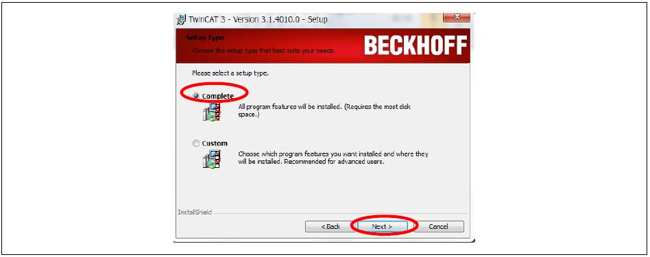
42 8 Installing and Running TwinCAT How to install 40
43 41
44 42
45 43
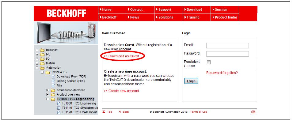
![8.2 Adding TwinCAT 3.0 Ethernet Protocol Follow the instructions below to activate the TwinCAT XAE software. From the Task Tray, click TwinCAT Config Mode > TwinCAT XAW] (VS2010).](/docs-images/75/72222629/images/46-0.jpg "Or, from the Start menu, click Beckhoff > TwinCAT3 > TwinCAT XAE (VS2010). Click the TwinCAT menu, and then click Show Realtime Ethernet Compatible Devices.")

46 8.2 Adding TwinCAT 3.0 Ethernet Protocol Follow the instructions below to activate the TwinCAT XAE software. From the Task Tray, click TwinCAT Config Mode > TwinCAT XAW] (VS2010). Or, from the Start menu, click Beckhoff > TwinCAT3 > TwinCAT XAE (VS2010). Click the TwinCAT menu, and then click Show Realtime Ethernet Compatible Devices. In the installation dialog window, compatible devices appear in the Installed and ready to use devices list. If all devices appear in the Incompatible devices list, the Ethernet adapter installed in the PC cannot be used with TwinCAT 3.0. Replace the Ethernet adapter if this is the case. Refer to the following link for a list of compatible Ethernet adapters: hercat_supnetworkcontroller.htm?id=


47 Select an adapter under the Installed and ready to use devices list, and them click Install. 45


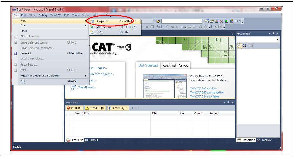
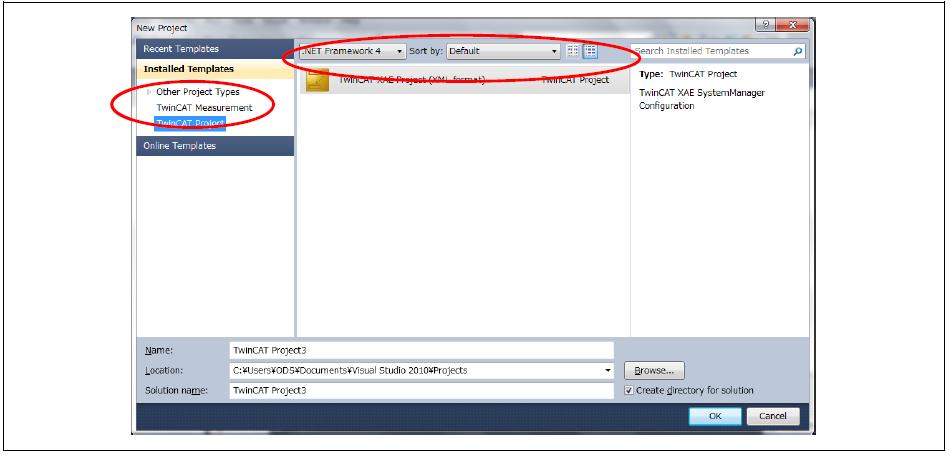
48 8.3 Copying the ESI Files Copy the S100_EtherCAT.xml or S100_EtherCAT.eds file to the \TwinCAT\Io\EtherCAT folder. Run the TwinCAT System Manager, and then click File > New to create a new project. 46
49 47


50 8.4 Scanning the I/O devices Right-click I/O Devices and select Scan Devices. Click OK when the following popup window appears: When a list of compatible Ethernet adapters is displayed as in the following figure, select an appropriate Ethernet port, and then click OK. 48

51 The S100 EtherCAT device is automatically recognized by TwinCAT after executing the procedures above. 49
52 8.5 Configuring Process Data Object (PDO) Select S100 EtherCAT first, and then click the Process Data tab on the right. Configure PDO sync manager in the tab. Rx PDO is transmitted to the S100 inverter from the master unit. Tx PDO is transmitted to the master unit from the S100 inverters. Rx PDO is assigned to Sync manager 2, and Tx PDO is assigned to Sync manager 3. The current PDO settings of the S100 inverter are loaded to TwinCAT when you click Load PDO info from device. 8.6 Creating a Task Select a PDO from the PDO list box. Modify the object mapping of the selected PDO in the PDO Context box (if necessary). Assign the PDO selected in the Sync Manager and PDO Assignment box to the Sync manager. Select PDO Assignment and PDO Configuration to allow TwinCAT to transmit settings to S100 inverters when network communication begins. In Config mode (within TwinCAT), you can restart the network communication by reloading the I/O device. Right-click Additional Tasks, and then select Append Task. Link the S100 I/O to the I/O of the appended task. Select Auto start in the Task tab (Additional Tasks > Task1) if you want to operate the S100 inverter as soon as the TwinCAT configuration is complete. 50
53 Maker Model No. Customer Information Sales Office (Distributor) LS Industrial Systems Co., Ltd. LV-S100 PROFInet Option Board Name Address Tel. Name Address Tel. Installation (Start-up) Date Warranty Period Warranty period is 12 months after installation or 18 months after manufactured when the installation date is unidentified. However, the guarantee term may vary on the sales term. IN-WARRANTY service information If the defective part has been identified under normal and proper use within the guarantee term, contact your local authorized LS distributor or LS Service center. OUT-OF WARRANTY service information The guarantee will not apply in the following cases, even if the guarantee term has not expired. Damage was caused by misuse, negligence or accident. Damage was caused by abnormal voltage and peripheral devices malfunction (failure). Damage was caused by improper repair or altering by other than LS authorized distributor or service center. Damage was caused by an earthquake, fire, flooding, lightning, or other natural calamities. When LS nameplate is not attached When the warranty period has expired. Revision History No Date Edition Changes First Release 51
Before using the product, thank you for purchasing SV-iS7 CANopen option board. SAFETY PRECAUTIONS
 Before using the product, thank you for purchasing SV-iS7 CANopen option board. SAFETY PRECAUTIONS Always follow safety instructions to prevent accidents and potential hazards from occurring. Safety precautions
SAFETY PRECAUTIONS CAUTION. WARNING Improper operation may result in serious personal injury or death.
 Safety Precautions Thank you for purchasing ig5a Series CANopen Communication Option Module. SAFETY PRECAUTIONS Always follow safety instructions to prevent accidents and potential hazards from occurring.
Safety PRECAUTIONS. Danger may be present. Read the message and follow the instructions carefully.
 Thank you for using our S100 PROFInet option module Safety PRECAUTIONS Always follow safety instructions to prevent accidents and potential hazards from occurring. Safety precautions are classified into
SAFETY PRECAUTIONS CAUTION WARNING CAUTION. Thank you for purchasing ig5a Series Profibus Communication Module
 SAFETY PRECAUTIONS Thank you for purchasing ig5a Series Profibus Communication Module SAFETY PRECAUTIONS Always follow safety instructions to prevent accidents and potential hazards from occurring. Safety
Before using the product, thank you for purchasing SV-iP5A CANopen option board. SAFETY PRECAUTIONS
 Before using the product, thank you for purchasing SV-iP5A CANopen option board. SAFETY PRECAUTIONS Always follow safety instructions to prevent accidents and potential hazards from occurring. Safety precautions
CAUTION. WARNING Improper operation may result in serious personal. CAUTION Improper operation may result in slight to medium
 Thank you for using our S100 Ethernet option module Safety PRECAUTIONS Always follow safety instructions to prevent accidents and potential hazards from occurring. Safety precautions are classified into
Thank you for purchasing S100 Series CANopen Communication Option Module. SAFETY PRECAUTIONS
 Safety Precautions Thank you for purchasing S100 Series CANopen Communication Option Module. SAFETY PRECAUTIONS Always follow safety instructions to prevent accidents and potential hazards from occurring.
Before using the product, thank you for purchasing SV-iS7 DeviceNet option board. SAFETY PRECAUTIONS
 Before using the product, thank you for purchasing SV-iS7 DeviceNet option board. SV - is7 DeviceNet Manual SAFETY PRECAUTIONS Always follow safety instructions to prevent accidents and potential hazards
Before using the product, thank you for purchasing MDLV-HP DeviceNet option board. SAFETY PRECAUTIONS
 Before using the product, thank you for purchasing MDLV-HP DeviceNet option board. SAFETY PRECAUTIONS Always follow safety instructions to prevent accidents and potential hazards from occurring. Safety
Before using the product, thank you for using our MD100G Ethernet option module Safety Instruction
 Before using the product, thank you for using our MD100G Ethernet option module Safety Instruction To prevent injury and danger in advance for safe and correct use of the product, be sure to follow the
Before using the product, thank you for using our Ethernet module board. Safety Instruction
 ig5a Ethernet Option Manual Before using the product, thank you for using our Ethernet module board. Safety Instruction To prevent injury and danger in advance for safe and correct use of the product,
Before using the product, thank you for using our MDLV-HP Ethernet option module. Safety Instruction
 Before using the product, thank you for using our MDLV-HP Ethernet option module. Safety Instruction To prevent injury and danger in advance for safe and correct use of the product, be sure to follow the
SAFETY PRECAUTIONS CAUTION. WARNING Improper operation may result in serious personal injury or death.
 Safety Precautions Thank you for purchasing MD100G Series Extension I/O. SAFETY PRECAUTIONS Always follow safety instructions to prevent accidents and potential hazards from occurring. Safety precautions
DS402 Implementation on Roboteq Motor Controllers
 DS402 Implementation on Roboteq Motor Controllers V1.0, February 24, 2018 visit www.roboteq.com to download the latest revision of this manual NOTE: DS402 is available since firmware v1.9 beta. Please
Safety Instruction. This symbol indicates the possibility of injury or damage to property.
 ig5a Ethernet Option Manual Safety Instruction To prevent injury and danger in advance for safe and correct use of the product, be sure to follow the Safety Instructions. The instructions are divided as
SAFETY PRECAUTIONS. Throughout this manual we use the following two illustrations to make you aware of safety considerations:
 Thank you for purchasing Marathon Drive (MD100P) RS485 Option Card! SAFETY PRECAUTIONS Always follow safety precautions to prevent accidents and potential hazards from occurring. In this manual, safety
User Manual. RS485 Option Board for SV-iS5/iH Series. LG Industrial Systems
 User Manual RS485 Option Board for SV-iS5/iH Series Read this manual carefully before using the RS485 OPTION BOARD and follow the instructions exactly. After reading this manual, keep it at handy for future
STF-EtherCAT User Manual
 STF-EtherCAT User Manual APPLIED MOTION PRODUCTS, INC. 1 Contents Introduction to EtherCAT... 4 Commonly Used Acronyms... 4 Protocol... 5 Logical Addressing...5 Auto Increment Addressing...5 Fixed Node
Thank you for purchasing ig5a Series DeviceNet Communication Module SAFETY PRECAUTIONS
 Safety Precautions Thank you for purchasing ig5a Series DeviceNet Communication Module SAFETY PRECAUTIONS Always follow safety instructions to prevent accidents and potential hazards from occurring. Safety
Options for ABB drives, converters and inverters. User s manual FECA-01 EtherCAT adapter module
 Options for ABB drives, converters and inverters User s manual FECA-01 EtherCAT adapter module List of related manuals See section Related manuals on page 16. EtherCAT is registered trademark and patented
EtherCAT User Manual. For STF EtherCAT
 EtherCAT User Manual For STF EtherCAT Table of Contents Introduction to EtherCAT... 3 Commonly Used Acronyms...3 Protocol...4 Logical Addressing... 4 Auto Increment Addressing...4 Fixed Node Addressing...4
Before using the product, thank you for using our MDLV-HP Pulse Encoder Interface Option Module. Safety Instruction
 Before using the product, thank you for using our MDLV-HP Pulse Encoder Interface Option Module. Safety Instruction To prevent injury and danger in advance for safe and correct use of the product, be sure
User Manual. RNet Option Board SV-iS7 Series. LS Industrial Systems
 User Manual RNet Option Board SV-iS7 Series * Use this board after read Safety Instruction of this manual carefully before using and follow the instructions exactly. * Please hand this user manual to end
EtherCAT User Manual. For SS EtherCAT
 EtherCAT User Manual For SS EtherCAT Table of Contents Introduction to EtherCAT... 3 Commonly Used Acronyms... 3 Protocol... 4 Logical Addressing... 4 Auto Increment Addressing... 4 Fixed Node Addressing...
Tritex II. CANopen - Option
 Tritex II CANopen - Option Contents Contents 2 Introduction... 8 1. CAN basics... 8 1.1. Data Frame... 8 1.2. Error Control... 9 1.3. Baud rate... 9 2. CANopen... 9 3. NMT... 10 3.1. NMT State Machine...
vacon optec installation manual ethercat option board ac drives
 vacon ac drives optec ethercat option board installation manual vacon 1 TABLE OF CONTENTS Document: DPD01207B Release date : 12/11/14 1. Safety...3 1.1 Danger...3 1.2 Warnings...4 1.3 Earthing and earth
User manual. MODBUS-RTU SV-iC5
 User manual MODBUS-RTU SV-iC5 - Read this manual carefully before installing, wiring, operating, servicing or inspecting the drive. Keep this manual within easy reach for quick reference. 1 Thank you for
Options for ABB drives, converters and inverters. User s manual FECA-01 EtherCAT adapter module
 Options for ABB drives, converters and inverters User s manual FECA-01 EtherCAT adapter module List of related manuals Drive manuals and guides Code (EN/Multilingual) ACS355 drives (0.37 22 kw, 0.5 30
SAFETY PRECAUTIONS. Always follow safety instructions to prevent accidents and potential hazards from occurring.
 Thank you for purchasing LONWORKS Option Board. SAFETY PRECAUTIONS Always follow safety instructions to prevent accidents and potential hazards from occurring. Safety precautions are classified into WARNING
CANopen MANUAL. TMCM axis stepper controller/driver board 2.8A RMS / 24V DC Encoder interface
 CANopen MODULES FOR STEPPER MOTORS MODULES CANopen Firmware Version V3.18 CANopen MANUAL TMCM-351 3-axis stepper controller/driver board 2.8A RMS / 24V DC Encoder interface TMCM-341 3-axis controller board
3 CH Analog Output module / CANopen
 3 CH Analog Output module / CANopen Power Supply 1..4 Vdc, 19..28 Vac Isolation 1,5 kvac (5 way) Accuracy,5% A/D resolution 14 bit Channels 3 Voltage range 1 V Current range..2, 4..2 ma RPDO < 2 ms (-1%
OPTEC. Ethercat option board installation manual
 OPTEC Ethercat option board installation manual Table of contents 1. SAFETY 1.1 Danger...1 1.2 Warnings...1 1.3 Earthing and earth fault protection...1 2. OPTEC ETHERCAT GENERAL 3. ETHERCAT OPTION BOARD
SK CU4-ECT-C Part number:
 SK CU4-ECT-C Part number: 275 271 517 EtherCAT Internal Bus Interface The bus interface may only be installed and commissioned by qualified electricians. An electrician is a person who, because of their
CANopen User manual Website: Technical Support: Skype: Phone: QQ: Technical forum:
 User manual Website: http://www.we-con.com.cn/en Technical Support: support@we-con.com.cn Skype: fcwkkj Phone: 86-591-87868869 QQ: 1043098682 Technical forum: http://wecon.freeforums.net/ 1. Installation
TOSVERT VF-S15 series CANopen Communication Function Manual
 1 TOSVERT VF-S15 series CANopen Communication Function Manual NOTICE 1. Read this manual before installing or operating. Keep this instruction manual on hand of the end user, and make use of this manual
CANopen CFW-11. Communication Manual. Phone: Fax: Web:
 Motors Automation Energy Transmission & Distribution Coatings CApen CFW-11 Communication Manual Language: English CApen Communication Manual Series: CFW-11 Language: English Document Number: 0899.5747
CANopen. Network configuration. Operating instructions Software. Integration of Bürkert devices in CANopen networks
 CANopen Network configuration Integration of Bürkert devices in CANopen networks Operating instructions Software Content CANopen quick guide 4 I. Setting the "CANopen" bus mode on the device 4 II. Setting
Commissioning the 9400 Highline TA CiA402 with EtherCAT and Beckhoff NC
 Commissioning the 9400 Highline TA CiA402 with EtherCAT and Beckhoff NC Contents 1. Preface/aim of the Application Report...2 2. Introduction...3 2.1. General information on EtherCAT...3 2.2. General information
Motors I Automation I Energy I Transmission & Distribution I Coatings. CANopen CFW500. User s Manual
 Motors I Automation I Energy I Transmission & Distribution I Coatings CANopen CFW500 User s Manual CANopen User s Manual Series: CFW500 Language: English Document Number: 10002253105 / 00 Publication Date:
hipecs-cio55 CANopen I/O module with 4 analog inputs
 General The hipecs-cio55 is a low-cost CANopen module with 4 analog input lines. The I/O are isolated from power supply and the CAN bus sub system. Furthermore, the module has an input resolution of 16
User Manual. PROFIBUS-DP Option Board for SV-iS5 Series. LG Industrial Systems
 User Manual PROFIBUS-DP Option Board for SV-iS5 Series Read this manual carefully before using the PROFIBUS-DP Option board and follow the instructions exactly. Keep it at handy for future reference. LG
Decentralized positioning drives
 Decentralized positioning drives MP-200 _Additional safety instructions _EtherCAT communication _Configuration / Parameterization _Troubleshooting / Diagnosis User Manual Interface TR - EMO - BA - GB -
Operating Manual. Inferface. CANopen. English
 Operating Manual Inferface CANopen English Disclaimer The information in this brochure corresponds to our current state of knowledge. However, it is not to be understood as a warranty for certain characteristics
Applied Motion Products CANopen Manual
 Applied Motion Products CANopen Manual APPLIED MOTION PRODUCTS, INC. Introduction This manual describes Applied Motion Products CANopen implementation of CiA 301 and CiA 402 specifications. It is expected
NOVOtechnik. Content. TIM CANopen Gebrauchsanleitung TIM CANopen user manual SIEDLE GRUPPE
 Content 9 CANopen 2 9.1 EDS Files 2 9.2 Features 2 9.2.1 Basic information 2 9.2.2 Basics based on CiA DS-301, V4.02 2 9.2.3 Basics based on CiA DSP-406, V3.2 3 9.2.4 Basics SDO communication 3 9.2.5 Basics
CANopen CFW100. User s Manual. Phone: Fax: Web: -
 CANopen CFW100 User s Manual CANopen User s Manual Series: CFW100 Language: English Document Number: 10002835377 / 00 Publication Date: 06/2014 CONTENTS CONTENTS... 3 ABOUT THE MANUAL... 5 ABBREVIATIONS
hipecs-cio52 CANopen I/O module with 4 analog outputs
 General The hipecs-cio52 is a low-cost CANopen module with 4 analog output lines. The I/O are isolated from power supply and the CAN bus sub system. Furthermore, the module has an output resolution of
hipecs-cio100 CANopen I/O module with 16/16 digital I/O
 General The hipecs-cio100 is a low cost CANopen unit with 16 digital inputs and 16 digital outputs suitable for 24 V DC applications. The I/O s are positive switching and opto-isolated from the bus and
LVD Digital Servo Drive
 Digital Servo Drive CApen Reference Manual Revision 2.0 Revision History Document Revision Date Remarks 2.0 Mar. 2012 1.0 Oct. 2011 Initial release Hardware Revision Firmware Revision Software Revision
Communications Manual
 Communications Manual MC 5010 MC5005 MC5004 MCS WE CREATE MOTION EN Imprint Version: 2nd edition, 9-12-2016 Copyright by Dr. Fritz Faulhaber GmbH & Co. KG Daimlerstr. 23 / 25 71101 Schönaich All rights
PLC2 Board Communication Manual CANopen Slave
 PLC2 Board Communication Manual CANopen Slave 02/2006 Series: PLC2 0899.5809 E/3 Contents Contents List of Tables 4 List of Figures 4 About the Manual 5 Abbreviations and Definitions...............................
Connection Guide HMS Industrial Networks
 Machine Automation Controller NJ-series EtherCAT(R) Connection Guide HMS Industrial Networks Anybus Communicator P560-E1-02 About Intellectual Property Rights and Trademarks Microsoft product screen shots
Connection Guide. SMC Corporation. EtherCAT(R) Machine Automation Controller NJ-series
 Machine Automation Controller NJ-series") Machine Automation Controller NJ-series EtherCAT(R) Connection Guide SMC Corporation EtherCAT Direct input type Step Motor Controller (Servo 24VDC) (JXCE1) P677-E1-01 About Intellectual Property Rights
Machine Automation Controller NJ-series EtherCAT(R) Connection Guide SMC Corporation EtherCAT Direct input type Step Motor Controller (Servo 24VDC) (JXCE1) P677-E1-01 About Intellectual Property Rights
EtherCAT for Pirani Capacitance Diaphragm and Pirani Standard Gauges
 Communication Protocol EtherCAT for Pirani Capacitance Diaphragm and Pirani Standard Gauges PCG550, PCG552, PCG554, PSG550, PSG552, PSG554 tira85e1-a (2014-10) 1 General Information Caution Caution: data
EtherCAT. CDG025D2 CDG045D CDG045D2 CDG045Dhs CDG100D CDG100D2 CDG100Dhs CDG160D CDG160Dhs CDG200D CDG200Dhs. Communication Protocol
 Communication Protocol EtherCAT for Capacitance Diaphragm Gauges CDG025D2 CDG045D CDG045D2 CDG045Dhs CDG100D CDG100D2 CDG100Dhs CDG160D CDG160Dhs CDG200D CDG200Dhs tirb45e1 (2019-02) 1 General Information
KHB EN.Cb> Ä.Cb>ä. Communication Manual. Servo Drives K. EtherCAT
 KHB 13.0005 EN.Cb> Ä.Cb>ä Communication Manual Servo Drives 930 931K EtherCAT i Contents 1 About this documentation.................................................. 4 1.1 Document history....................................................
LXM23A CANopen Fieldbus protocol for servo drive Fieldbus manual V2.00,
 Fieldbus protocol for servo drive Fieldbus manual V2.00, 10.2011 www.schneider-electric.com Important information LXM23A CANopen Important information This manual is part of the product. Carefully read
YASKAWA AC Drive A1000 Option. Technical Manual
 YASKAWA AC Drive A1000 Option Technical Manual Type: SI-ES3 for A1000 Series To properly use the product, read this manual thoroughly and retain for easy reference, inspection, and maintenance. Ensure
E2 Modbus RTU Register Map Revision History Version Comments Author Date 1.02 Previous version PAE 11/06/ Revised to new format PAE 09/03/09
 Application Note Title AN-ODE-01 E2 Modbus RTU Register Map Revision History Version Comments Author Date 1.02 Previous version PAE 11/06/08 1.03 Revised to new format PAE 09/03/09 General This document
EtherCAT(R) Connection Guide IAI Corporation
 Connection Guide IAI Corporation") Machine Automation Controller NJ-series EtherCAT(R) Connection Guide IAI Corporation X-SEL Controller (XSEL-R/S/RX/SX/RXD/SXD) P549-E1-01 About Intellectual Property Rights and Trademarks Microsoft product
Machine Automation Controller NJ-series EtherCAT(R) Connection Guide IAI Corporation X-SEL Controller (XSEL-R/S/RX/SX/RXD/SXD) P549-E1-01 About Intellectual Property Rights and Trademarks Microsoft product
ABB Drives. User s Manual. Modbus Adapter Module RMBA-01
 ABB Drives User s Manual Modbus Adapter Module RMBA-01 Modbus Adapter Module RMBA-01 User s Manual 3AFE 64498851 REV A EN EFFECTIVE: 1.3.2002 2002 ABB Oy. All Rights Reserved. Safety instructions Overview
4 Interpolated Position Mode
 In Brief 4 Interpolated Position Mode 4.1 In Brief A wide variety of operating modes permit flexible configuration of drive and automation systems by using positioning, speed and current regulation. The
hipecs-cio56 CANopen I/O module with PT100/1000 inputs
 General The hipecs-cio56 is a powerful, low-cost CANopen module for temperature measuring via PT100/1000. According to demands 2-, 3- or 4-wire-connection is usable. Up to 4 channels using 2-wire-connection
NOVOtechnik SIEDLE GRUPPE
 Content 1 CANopen 2 1.1 EDS Files 2 1.2 Features 2 1.2.1 Basic information 2 1.2.2 Basics based on CiA DS-301, V4.2.0 2 1.2.3 Basics based on CiA DSP-406, V3.2 3 1.2.4 Basics SDO communication 3 1.2.5
Supplementary device manual EtherCAT interface in the AS-i controllere A AC1391 AC1392
 Supplementary device manual EtherCAT interface in the AS-i controllere A AC1391 AC139 firmware version RTS.x target from 15 for CoDeSys from version.3 English 739071_00_UK 01-0- Contents Revision: 16 December
SAFETY PRECAUTIONS. Always follow safety instructions to prevent accidents and potential hazards from occurring.
 Thank you for purchasing LONWORKS Option Board. SAFETY PRECAUTIONS Always follow safety instructions to prevent accidents and potential hazards from occurring. Safety precautions are classified into WARNING
Connection Guide FANUC CORPORATION
 Machine Automation Controller NJ-series EtherCAT(R) Connection Guide FANUC CORPORATION R-30iB Robot Controller P605-E1-01 About Intellectual Property Rights and Trademarks Microsoft product screen shots
User Manual. NanoCAN. Application for stepper motor controls and Plug & Drive motors (version V )
") User Manual Application for stepper motor controls and Plug & Drive motors (version V2.0.0.1) NANOTEC ELECTRONIC GmbH & Co. KG Kapellenstraße 6 D-85622 Feldkirchen b. Munich, Germany Tel. +49 (0)89-900
User Manual Application for stepper motor controls and Plug & Drive motors (version V2.0.0.1) NANOTEC ELECTRONIC GmbH & Co. KG Kapellenstraße 6 D-85622 Feldkirchen b. Munich, Germany Tel. +49 (0)89-900
CANopen IO X1 Fact sheet
 CANopen IO X Fact sheet Overview The CANopen IO X is a very compact and cost effective CANopen IO module featuring a high-density of industrial proven I/O's. The module includes a CPU-core including the
Motors Automation Energy Transmission & Distribution Coatings. Software WSCAN. User's Manual
 Motors Automation Energy Transmission & Distribution Coatings Software WSCAN User's Manual User's Manual Series: WSCAN V2.0X Language: English Publication Date: 11/2010 Content 3 Index 0 Parte I General
CEM M-RS485 INSTRUCTION MANUAL (M014B A)
") Communications interface CEM M-RS485 INSTRUCTION MANUAL (M014B01-03-14A) 2 SAFETY PRECAUTIONS Follow the warnings described in this manual with the symbols shown below. DANGER Warns of a risk, which could
Communications interface CEM M-RS485 INSTRUCTION MANUAL (M014B01-03-14A) 2 SAFETY PRECAUTIONS Follow the warnings described in this manual with the symbols shown below. DANGER Warns of a risk, which could
BMS CAN Manual. V2.0, September 3, 2018 Visit to download the latest revision of this manual Copyright 2018 Roboteq, Inc
 BMS CAN Manual V2.0, September 3, 2018 Visit www.roboteq.com to download the latest revision of this manual Copyright 2018 Roboteq, Inc Copyright Roboteq Inc. 2018. All Rights Reserved. Table of Contents
SK CU4-CAO Part number:
 SK CU4-CAO Part number: 275 271 001 CANopen Internal Bus Interface The bus interface may only be installed and commissioned by qualified electricians. An electrician is a person who, because of their technical
E2 Modbus RTU Register Map
 Application Note AN ODE 01 E2 Modbus RTU Register Map Author: Peter Evans, Invertek Drives Ltd Revision: 1.02 11 June 2008 Software Version: 1.02 General This document details the Modbus RTU memory mapping
- Alii -,..., ~~~~~~~~'-~" ..., ,..- ))) --t ..., )(1. User s manual FEPL-02 Ethernet POWERLINK adapter module. IIIIIJ!ll"
)) --t ..., )(1. User s manual FEPL-02 Ethernet POWERLINK adapter module. IIIIIJ!ll") Options for ABB drives, converters and inverters User s manual FEPL-02 Ethernet POWERLINK adapter module,..- ))) --t - Alii - -,...,..., IIIIIJ!ll"...,,, FEPL ~ 02,.., " ETHERNET powerljnk ADApTER _,,""
Options for ABB drives, converters and inverters User s manual FEPL-02 Ethernet POWERLINK adapter module,..- ))) --t - Alii - -,...,..., IIIIIJ!ll"...,,, FEPL ~ 02,.., " ETHERNET powerljnk ADApTER _,,""
SANYO DENKI Servo Amplifier SANMOTION R and Pro-face AGP-3****-CA1M/LT Connection Procedure. Instruction Manual. Version1.0 (
 SANYO DENKI Servo Amplifier SANMOTION R and Pro-face AGP-3****-CA1M/LT Connection Procedure Instruction Manual Version1.0 (2009.2.25) Table of Contents 1 Applicable devices... 1 2 Installation of GP-Pro
CANopen Fieldbus manual MDrive Motion Control Products
 CANopen Fieldbus manual MDrive Motion Control Products CANopen Fieldbus Manual Date Revision Changes 05/12/2010 R051211 Initial release. This document replaces and supercedes CANopen implementation manual
Machine Automation Controller NJ-series. EtherCAT(R) Connection Guide. Balluff GmbH. Network Interface (BNI ECT-508) P673-E1-01
 Connection Guide. Balluff GmbH. Network Interface (BNI ECT-508) P673-E1-01") Machine Automation Controller NJ-series EtherCAT(R) Connection Guide Balluff GmbH Network Interface (BNI ECT-508) P673-E1-01 About Intellectual Property Rights and Trademarks Microsoft product screen shots
Machine Automation Controller NJ-series EtherCAT(R) Connection Guide Balluff GmbH Network Interface (BNI ECT-508) P673-E1-01 About Intellectual Property Rights and Trademarks Microsoft product screen shots
CANopen Communications Module CB16. Operating Instructions. Operating Instructions for. CANopen Communications Module
 CANopen Communications Module CB16 Operating Instructions for CANopen Communications Module for Siemens MICROMASTER Vector / MIDIMASTER Vector (6SE32 ) General Purpose Inverters. Operating Instructions
Ethernet/IP Module. User Manual. Contents
 User Manual Contents 1 Important User Information... 2 2 Installation... 3 3 Connection... 4 4 Device Configuration... 5 5 Operation... 8 6 Packet Structures... 9 7 Network Design... 18 8 Specifications...
UNIDRIVE SP AFFINITY DIGITAX ST DIGIDRIVE SK MENTOR MP
 4463 en - 2009.12 / a UNIDRIVE SP AFFINITY DIGITAX ST DIGIDRIVE SK MENTOR MP START Ensure the CT.xml file is in the appropriate folder on the hard drive of the master Check the LED status of the SM-EtherCAT
Quick Start Guide PN/CAN-Gateway. Version. 1 en. from FW
 Quick Start Guide PN/CAN-Gateway Version 1 en from FW 1.00 www.helmholz.com Content 1. Introduction 3 2. Preparation of the PN/CAN-Gateway 3 3. Plan PN/CAN-Gateway 4 4. Configure PN/CAN-Gateway 5 5. Add
PHOENIX CONTACT GmbH & Co. KG
 Machine Automation Controller NJ-series EtherCAT(R) Connection Guide PHOENIX CONTACT GmbH & Co. KG I/O SYSTEM (Axioline F Series) P621-E1-01 About Intellectual Property Rights and Trademarks Microsoft
DELTA ELECTRICS, INC.
 Machine Automation Controller NJ-series EtherCAT(R) Connection Guide DELTA ELECTRICS, INC. EtherCAT Slave Remote module (R1-EC Series) P655-E1-01 About Intellectual Property Rights and Trademarks Microsoft
CANopen. Technical Guide for Delta ASDA-A2
 CANopen Technical Guide for Delta ASDA-A2 Version: V1.01 Date: December, 2009 This page intentionally left blank Manual Overview Please include the Manual Number and the Manual Version shown below when
SGH Cable Actuated Sensor Industrial CANOpen
 Cable Actuated Sensor Industrial CANOpen Two Available Stroke Ranges: 0-80 in & 0-120 in. Rugged Polycarbonate Enclosure Simple Installation Compact Design Built for IP67 environments IN STOCK FOR QUICK
CANopen Library User Manual
 CANopen Library User Manual V1.03 June 2010-1 - Table of Contents 1. Introduction... 1 1.1. CANopen architecture... 1 1.2. Object Dictionary setting... 3 1.2.1. Service Data Objects (SDO)... 4 1.2.2. Process
Positioning Controller
 Edition December 2008 Positioning Controller Introduction Application Note "Interpolation Position Mode" Edition December 2008 EPOS2 50/5, EPOS Module 36/2 Firmware version 2101h or higher The EPOS2 positioning
Profinet Module. User Manual. Contents
 User Manual Contents 1 Important User Information... 2 2 Installation... 3 3 Connection... 4 4 Device Configuration... 5 5 Operation... 7 6 Packet Structures... 8 7 Network Design... 16 8 Specifications...
CANopen IO X4 Fact sheet
 CANopen IO X4 Fact sheet Overview The CANopen IO X4 is a very compact and cost effective CANopen IO module featuring a high-density of industrial proven IO's. The module includes a CPU-core including the
Quick Start Guide RSi S Series VFD. Using the 7-segment (4 digit LED) Keypad/Display
 Keypad/Display") Quick Start Guide RSi S Series VFD Pub. # 8900490100 Using the 7segment (4 digit LED) Keypad/Display Contents 1. Display and Keypad Buttons Operation... 2 2. Wiring... 3 A. Power Terminals... 3 B. Control
Quick Start Guide RSi S Series VFD Pub. # 8900490100 Using the 7segment (4 digit LED) Keypad/Display Contents 1. Display and Keypad Buttons Operation... 2 2. Wiring... 3 A. Power Terminals... 3 B. Control
Positioning Controller
 Positioning Controller Application Note "CANopen Basic Information" Edition February 2006 EPOS 24/1, EPOS 24/5, EPOS 70/10 Firmware version 2000h or higher Introduction The EPOS is a digital positioning
Communications Manual MC 5010 MC 5005 MC 5004 MCS RS232 / WE CREATE MOTION
 Communications Manual MC 5010 MC 5005 MC 5004 MCS RS232 / WE CREATE MOTION EN Imprint Version: 15-04-2016 Copyright by Dr. Fritz Faulhaber GmbH & Co. KG Daimlerstr. 23 / 25 71101 Schönaich All rights reserved,
Machine Automation Controller NJ-series. EtherCAT. Connection Guide. OMRON Corporation. Digital Sensor Communication Unit (E3NW-ECT) P563-E1-01
 P563-E1-01") Machine Automation Controller NJ-series EtherCAT Connection Guide OMRON Corporation Digital Sensor Communication Unit (E3NW-ECT) P563-E1-01 About Intellectual Property Right and Trademarks Microsoft product
Machine Automation Controller NJ-series EtherCAT Connection Guide OMRON Corporation Digital Sensor Communication Unit (E3NW-ECT) P563-E1-01 About Intellectual Property Right and Trademarks Microsoft product
No. FST-ZTH13079B. Machine Automation Controller NJ-series. EtherCAT Connection Guide. Kollmorgen Corporation Servo Drive (AKD )
") No. FST-ZTH13079B Machine Automation Controller NJ-series EtherCAT Connection Guide Kollmorgen Corporation Servo Drive (AKD ) About Intellectual Property Rights and Trademarks Microsoft product screen
No. FST-ZTH13079B Machine Automation Controller NJ-series EtherCAT Connection Guide Kollmorgen Corporation Servo Drive (AKD ) About Intellectual Property Rights and Trademarks Microsoft product screen
CANopen IO X2 Fact sheet
 CANopen IO X2 Fact sheet Overview The CANopen IO X2 is a very compact and cost effective CANopen IO module featuring a high-density of industrial proven I/O's. The module includes a CPU-core including
IFD9503. CANopen Slave Communication Module Application Manual
 IFD9503 CANopen Slave Communication Module Application Manual Warning Please read this instruction carefully before use and follow this instruction to operate the device in order to prevent damages on
MODBUS RTU MODULE INSTRUCTIONS. for use with WSIQ2/WSE
 INSTRUCTIONS MODBUS RTU MODULE for use with WSIQ2/WSE WorldWide Electric Corporation Phone: 1-8-88-2131 Fax: 1-8-711-1616 www.worldwideelectric.net Product Compatibility This communications module is suitable
CANopen Interface for SG5 and SG7
 CANopen Interface for SG5 and SG7 User Manual This document applies to the following drives: E12x0-xx-xx-xxx (SG5) E14x0-xx-xx-xxx (SG5) C11x0-xx-xx-xxx (SG7) A11x0-xx-xx-xxx (SG7) (with CANopen Interface
Chapter 5: Communications 5 1 SR55 Communications Overview 5 2
 Chapter 5 Table of Contents Chapter 5: Communications 5 1 SR55 Communications Overview 5 2 Modbus Serial Communications Overview 5 2 Modbus TCP Network Communications Overview 5 2 EtherNet/IP Network Communications