BRADYMARKER XC Plus Printer
|
|
|
- Anastasia Robbins
- 6 years ago
- Views:
Transcription
1 Introduction Features and capabilities PermaSleeve adaptation Basic Operations Setup, menu, keyboard, memory BRADYMARKER XC Plus Printer Tutorial Installation of labels and ribbons, working with the menu, printing and serializing labels Cleaning and maintenance Basic cleaning instructions, removal and reinstallation of paper shoot Troubleshooting Most commonly asked questions Operational exercise Page 1
2 Page 2
3 Introduction to BMXC+ The BMXC+ is a nine pin dot matrix portable printer capable of printing wire markers, electronic component labels, and general identification labels. Label registration is accomplished by optically sensing labels insuring proper label alignment. It is capable of printing eight lines per inch and 23 characters per line. There are three text sizes and three formats available. Full justification is another feature on the BMXC+. The display is a two line 24 character liquid crystal display. Standard memory is 8K and can be expanded to 32K. Files can be created and stored in the BMXC+ for later usage. Print functions include multiple copies and automatic numeric or alphabetic serialization. The BMXC+ can be run on battery or AC power. The battery charger is a UL listed 120V, 60Hz input/12vac, 2A output adapter. It will print 500 labels before recharging. PermaSleeve printing is available on the BMXC+-PS. The BMXC+ can be adapted to handle this type of printing. Page 3
4 Legend entry screen Page 4
5 Basic Operations Menu Size Format Quantity Justify Type This is the material size code. It can be obtained from the box or from the inner core of the label. The parameters for the legend is determined by this size code. There are three formats on the BMXC+: wiremarker, component, and strip. Wiremarker mode automatically repeats the line of text in the legend down the length of the marker. Component mode will print all of your legend a single time. It will automatically center your text vertically. Strip (wiremarker) mode is identical to the wiremarker format except that it allows you to print duplicate markers on a multiple across label (a butt cut label). This format will always print the same text in each strip of label. It is considered a single label for printing and serialization. This mode will print either in the Single Marker mode and print one marker for each print command or print in the Multiple Marker mode and print more than one marker from the print mode. You will be prompted for the number of markers to print. This will allow center, left or right justification on your marker. All text must be printed using the same justification. This setting is NOT held in memory with your legend list. Normal = 12 cpi; Small = 16 cpi; Large = 8 cpi and half height = 16 cpi. A single size text is selected and will remain until a new type size is selected. Changing the type size will erase any test on the legend screen. List This is the area in which files are stored in memory. The BMXC+ can store up to 26 unique legend lists. It can store up to 6500 characters of legend information in its standard 8k memory. The memory can be expanded to 32k. The LIST part of the MENU has a submenu which includes Create, Print, View/Edit, Add to, and Erase. Each of the selections deal with the List (saved) files. Page 5
6 Keyboard Help Clear Display Save Enter Exit/Stop Serial Recall Arrows Insert Delete Menu Print Reprint Feed You can press this key any time. It will direct you to the appropriate section of the user manual for further information. Clears all characters from the Legend Entry Screen. This works in conjunction with the LIST selection in the MENU. It will store the current legend into the list that you are creating. This key can act like a carriage return to add another line to the legend. It also acts to select options from any part of the menu when it is highlighted. This key will move from a submenu to the menu screen or from the menu screen to the Legend Entry Screen. It will also terminate the printing of markers. Press this key to define an individual character to be serialized. Allows sequential viewing of legends in a created list. Moves the cursor in the direction of the arrow. This toggles the text to type- over a character or insert a character. If the cursor is flashing, it will type over the character. If it isn't it will insert a character. Erases the character currently at the cursor. Moves from the legend entry screen to the main menu. Hold this key down to display your current main menu settings. Prints the legend currently displayed or to begin printing markers from a legend list. Duplicates he last marker printed. Advances the marker roll to the next marker. Use this to initially load the markers. Page 6
7 Paper shoot & material guide assembly This is a three piece mechanical assembly through which the material (labels) pass before being printed. This section can be taken apart for easy removal of labels that may have gotten stuck in the unit. Optic eye The optic eye is the material sensing device on the BMXC's. It senses the "cut-out" on the material to align the marker for proper print positioning. Ribbon The BMXC+ uses the R2200 ribbon. The BMXC+-PS uses the R5200 ribbon. Battery pack The battery pack must be charged for 16 hours with the AC adapter/charger prior to usage for optimal performance. To ensure proper charging, the barrel plug must be fully inserted inside the power jack. Only the molded housing should be visible. The battery pack will last through 2-3 years of chargings. A fully charged unit should last through a few days of continual usage. Any nicad battery should be run until the "battery low" warning is displayed before recharging. Page 7
8 BMXC+ marker size codes Characters per line Marker Width (inches) Label Size Normal Size Small Size Large Size.17 x x x x x x x x x x x x x x x x x Page 8

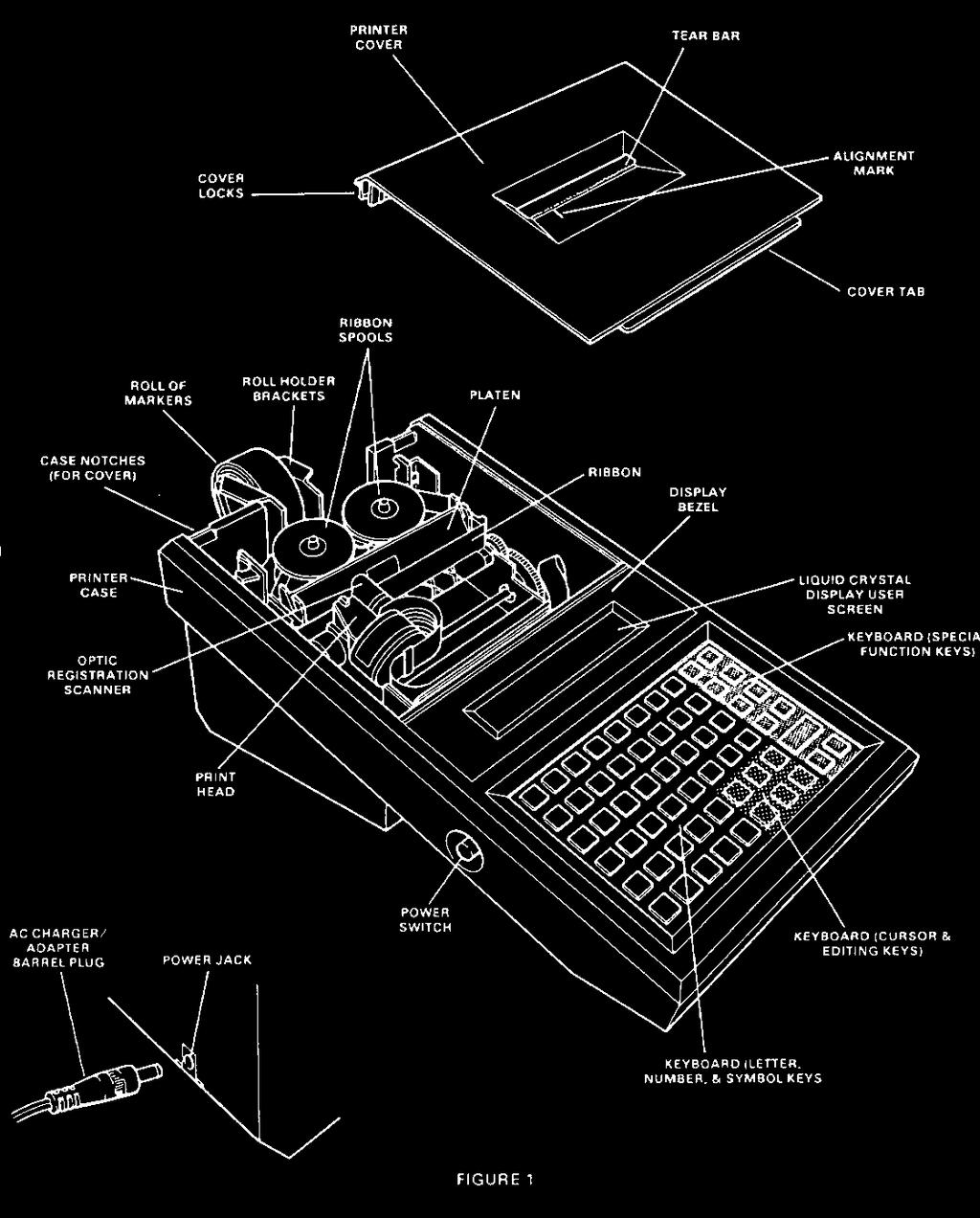
9 BRADYMARKER PS printer A. General unit description The Bradymarker PS printer is a Bradymarker XC Plus printer which has been modified to allow it to print PermaSleeve wire marking sleeves, in addition to all other Bradymarker consumables. This section will address changes and additions found in the PS model. Differences between the two versions of printer include the following (refer to Fig. 1, pg. 1). 1. The print head features a gap adjuster mechanism on the PS version (see Section B). 2. A print cover with no tear bar is needed when using PSBX sleeves (two different covers are included with a PS unit). 3. The roll holder brackets are replaced with a roll unwind assembly for PSBX sleeves. When PermaSleeve markers are to be printed with the unit, make sure the roll unwind assembly and PS printer cover (no tear bar) are installed on the unit. Set the print head gap as in Section B. Store the roll holder brackets and Plus printer cover (with tear bar) in the Bradymarker carrying case for future use (see Section E, pg. 8). B. Setting the print head gap The Bradymarker PS printer features a print head gap adjuster mechanism, which allows it to compensate for material thickness. The gap is adjusted as follows (refer to Fig. A): 1. Remove the print cover. 2. Using a slotted screwdriver, loosen the adjuster lock screw by turning it one revolution counter-clockwise. Page 9
10 BRADYMARKER PS printer 3. With screwdriver, turn the plastic gap adjustment screw (turn clockwise only!) To the desired setting. The smallest gap (locator dots at 12 o clock) is used for all non- PermaSleeve consumables. The next smallest gap (4 o clock) is the standard setting for PermaSleeve markers. The final position (7 o clock) should only be used if the printer smears with the 4 o clock setting. 4. With screwdriver, re-tighten adjuster lock screw. Be careful not to over-tighten screw! 5. Replace printer cover. When adjusting the print head gap, be careful not to move the optic scanner within its plastic holder. The scanner position is critical to proper machine operation. If scanner is accidentally moved, refer to (Section F, pg. 10) for instructions on resetting the scanner gap. C. Setting the unit for sleeve size Follow the instructions on page 11 in the tutorial section Press the MENU key.... Like other Bradymarker labels, PermaSleeve markers have the marker size code shown on the package and on the inside of the roll core. After entering the marker size code and the appropriate format option, you will be asked the question. Printing PSBX sleeves? Press Y or N. Select Y in using PermaSleeve markers; select N in all other cases. This will set the proper margin for the printer. This is necessary due to PermaSleeve marker s different location (leftto-right) on its carrier than other Bradymarker labels. D. Loading PermaSleeve wire marker sleeves Before attempting to load PermaSleeve markers, make sure that unwind assembly and proper printer cover are in place, material guide is set to widest position, and correct marker size information had been entered. Load PermaSleeve markers as follows (refer to Fig. B). 1. Make sure power in ON. 2. With the leading end approximately on top of the roll, set the roll of sleeves into the unwind assembly so that they will unwind in the direction shown in Fig. B on the next page. 3. Turn the roll backwards (opposite the arrow in Fig. B) until the leading edge pops under the front roller in the unwind assembly. Page 10
11 BRADYMARKER PS printer (continued) 4. Reverse direction and turn the roll forward. Feed material into printer until it stops. The leading edge will now be positioned against the drive roller. 5. While continuing to hold the roll so that the leading edge is pushed tightly against the drive roll, press and hold the FEED key. The drive roller will begin to pull markers into the printer. Continue to hold the FEED key until the leading edge of the roll becomes visible through the slot in the top of the printer cover. 6. Release the FEED key. The printer should advance to the top of the first available PermaSleeve marker. You are now ready to enter legends and print sleeves. WARNING - NEVER try to remove any Bradymarker label or sleeve by pulling them out of the rear of the printer. The printer drive is one-way only. To remove markers, insert a scissors in the slot for scissors in the unwind assembly (see Fig. B), cut through the carrier between sleeves, and pull the sleeve out though the top of the printer. Page 11
12 BRADYMARKER PS printer (continued) E. Printing other markers To print Bradymaker labels other than PermaSleeve marker. 1. Replace the unwind assembly with the roll holder brackets (See Fig. 1, pg.1). 2. Replace the printer cover with the standard Plus cover (with tear bar). Store the unused items in the Bradymarker carrying case for future use. Set the print gap to its smallest setting, as described in Section B, pg. 7. Then follow the instructions in the tutorial section. F. Maintenance & Troubleshooting In general, follow the instructions in the cleaning & maintenance and troubleshooting sections. Pay particular attention to the following items. 1. The drive roller and nip roller o-ring need to be cleaned occasionally to ensure proper feeding through the printer. Refer to A stuck label removal, for instructions on removing and installing the material chute assembly. Clean both the drive roller and nip roller o-rings with isopropyl alcohol. 2. The position of the optic scanner within the print head gap adjuster mechanism is critical. If bumped, the scanner may move inside its holder, resulting in one of the following *error messages. The front end of the metal optic scanner should be aligned with the bottom front edge of the plastic holding clip. Gently slide the scanner inside the holding clip to re-align, if necessary. * Please verify size Scanning error Out of markers Page 12
13 Tutorial Before using, charge the internal battery pack by plugging it into the AC adapter/charger and allowing it to charge for 16 hours or more. Install the ribbon onto the ribbon spool shaft with the spool drive pins pointing down. Push the ribbon detector lever away from the spoon shaft, press down on the ribbon spool until it clicks into place, then release the ribbon detecting lever. Repeat the process for the other side. Tighten the ribbon by turning the right spool in a clockwise direction. Move the material guide (on the paper shoot) to the appropriate size for the material selected. Insert the material into the shoot. Turn the unit on and press Feed. This will advance the material into the printer. Press the MENU key and Press "S" for Size. Enter the size code of the material being used. This should be on the inside of the material core and on the outside of the material box. Press Enter. Next select the label format (Wiremarker, Component, Strip) Press Enter. (Enter acknowledges acceptance of the selection) Next go through the Menu and select the Type size, Quantity Cycle, and Justification needed for your application. Remember to press Enter to accept each entry. Enter the legend to be printed. Press the Print key. If you are in Multiple mode it will prompt you as to the quantity of each marker to print. To serialize enter your legend and place the cursor under the character to be serialized. Press the Serial key. The character block will be blinking. If more than one number will be incremented, each character must be serialized (blinking). Example - the starting number is 1234 and the final number is 1250, the last two characters must be selected and serialized (by pressing the Serial key) for them to increment. Serialized characters are always incremented by one number or one letter. Press Print and enter the number of each identical labels to be printed (this is usually 1), press Enter. You will be prompted for the "Number of Times to Increment a Serial #". Enter the total number to incremented labels you want (not the number you want the unit to increment to). The BMXC+ will increment the character furthest to the right first. When it reaches 0 or Z the next character will start incrementing. To save a legend in memory, first select Menu and press L for List, select Create (press Enter) and select any of the lower case letters. Type in your legend and press Save. This will add the legend to the memory. The LCD will display the "Legend will be added to List "X" message. Press Clear Display and type in the next legend to be saved. Press Save. It is possible to add to this List at a later date by selecting the Add To feature in the Menu and enter legends as before. A List can be edited by using the View/Edit command. If you know the letter of the List you want to print, you can select Print from the List Menu and enter the number of each label to be printed. Page 13
14 Tutorial (continued) IMPORTANT Be sure to choose the label size, font size, and justification before going into the List feature. These settings will be saved with the file saved. To Erase a List from memory, select Menu, List, the name of the file, and press Erase. You will be prompted "Erase List "X", press Y or N. Page 14
15 Ribbon Installation Page 15
16 Cleaning and maintenance A. Cleaning and lubrication The printer is a rugged mechanism. It should be cleaned and lubricated as indicated below, to keep it in top operating condition. 1. Cleaning: Several areas need occasional cleaning. See Figure 5 on the next page. a) First is the platen. White paper lint collects on the black tape attached to the platen causing the optic registration system to misread the notch on the label liner. Clean this at least once every month using alcohol on a cotton swab. b) Second is the ink ribbon guide path. The ink has a tendency to build a thick pastelike material on the two outside ribbon guides. This increases the driving friction of the ink ribbon, which causes the drive pins on the ink ribbon spool to fail. Clean these ribbon guides with a small amount of alcohol on a cotton swab each time you install a new ribbon. c) Third is the print head. Poor print quality or missing print dots may be an indication that your print head requires cleaning. A Brady printer cleaning kit is available from your W. H. Brady Co. Distributor (catalog # PCK-1). Use the cleaning kit and follow the instructions below: 1. While holding down the H key, turn the printer on. 2. Follow the instructions as displayed on the user screen. IMPORTANT Be sure to remove the ribbon before you try to clean the print head. The print head should be cleaned using a strip of print element cleaning material that is 1 3/4" wide by approximately 6" long. Saturate the first 4" of the strip with cleaning solution before feeding into the printer. Feed the strip so that the wet side is facing the print head. Loose cleaning material can severely damage the printer. If you tear material along perforations, be sure to trim all the edges of the cleaning strip. Be sure to thoroughly clean the print head. You may need to run more than one cleaning material strip through the printer to completely clean the print head. If your printing quality does not improve, you may have a worn ribbon. Replacement ribbons (catalog # R2100) are available from your W. H. Brady Co. Distributor. Page 16
17 2. Lubrication Figure 5 also indicates those points on the printer mechanism that require periodic lubrication. Oil points are noted by an O grease points by a G. Before lubricating any location, make sure that it is wiped clean of any dirt and old lubricant. Always apply a minimum amount of lubricant. a) Apply a good quality grade of #40 lubricating oil to all oil points every six months. b) Apply a good quality #1 grease to all grease points every 12 months. Note: The shaft that the print head travels across must be lubricated with #1 grease. Lubricating with oil will damage this shaft. Page 17
18 B. Battery pack replacement Battery pack life will depend upon usage and operating conditions. When recharging the battery pack, always recharge at least 16 hours to restore full power to the pack. This will result in longer battery pack life. If you find that your battery pack is no longer holding a sufficient charge, you should replace it with a new battery pack assembly (part # 29415). To replace the battery pack assembly follow these instructions. 1. Remove the bottom rear cover and the bottom front cover. 2. Slide the battery pack power jack from the slot in the edge of the printer body. 3. Disconnect the battery pack connector from the printed circuit board. Carefully slide the connector through the opening at the center of the printer. 4. Remove the screw holding the battery pack assembly clamp to the bottom rear cover. Note the proper position of the battery pack wire leads. 5. Clamp the new battery pack assembly to the bottom rear cover, making sure that the wire leads are in the correct position. 6. Push the battery pack connector through the opening at the center of the printer body. Make sure that the terminals are located on the correct side to provide clearance from the printer case. 7. Slide the battery pack power jack into the slot in the edge of the printer body. Make sure that the terminals are located on the correct side to provide clearance from the printer case. 8. Replace the bottom rear cover and bottom front cover. C. Lithium battery replacement The printed circuit board has a lithium backup battery. This battery prevents the loss of stored legend lists in cases where the battery pack has been completely drained and the printer is not connected to a 120V power source. Clean the unit OFTEN. Even if not in use, the environment will leave dust in the unit which may obstruct the optic sensor. Included in the cleaning should be the white ribbon rewind tape on the right and left side of the platen (remove the ribbon to see this tape) The black platen tape cannot be replaced with electrical tape. The reflective qualities of this tape is different than factory tape. The optic sensor should be flush with the front most part of the housing. A silver section will protrude from the back of the housing. The optic sensor is factory set and does not need adjustment. Page 18
19 D. Stuck label removal Page 19
20 D. Stuck label removal (continued) If a label becomes stuck inside the printer and can not be seen from outside the printer, it is probably stuck to the rubber feed roller. 1. To remove the label, first remove the bottom rear cover, the marker roll and roll holders. (See Figure 1, pg. 1 and Figure 7, this page). 2. Remove the material chute assembly by gently pressing the locking tabs away from the material chute assembly, then lift the material chute assembly out of the printer case. 3. The rubber feed roller is now visible. Remove the label and clean any adhesive residue off the roller using isopropyl alcohol. 4. Replace the material chute assembly. It is important that the two sets of key tabs are properly inserted into the key slots. One set of key tabs and slots is not visible. To engage the key tabs, push paper chute assembly down while pulling it toward the back of the printer. You should feel the key tabs snap into place. 5. Be sure that the material guide is properly positioned between the alignment slots, then push the material chute assembly down so that the alignment tabs push through the alignment slots. 6. Work the material chute assembly under one of the locking tabs. Then insert a screwdriver or other pointed instrument through the material path opening. Push the other locking tab while pushing down on the material chute assembly. The material chute assembly will snap into place under the locking tab. 7. Test the position of the material chute assembly by turning the idler roller. You should feel some resistance. If not, the hidden set of key tabs are probably not installed properly. Reinstall the material chute assembly and again turn the idler roller. 8. Replace the bottom cover. Page 20
21 Additional tips (continued) If the unit must come in for repair: 1. An RMA must be obtained from Brady s Tech Support Center at 800\ When ready to ship the unit in, write up a short note stating the symptoms and enclose any samples that show the problem. 3. Send the unit in it's protective case, if available, or wrap the unit in 2" - 3" of plastic bubble wrap. Secure the bubble wrap around the unit. This will protect it from damage in shipment. ** DO NOT use styrofoam or biodegradable peanuts. They break down during shipment and get into the unit causing extensive cleaning and possible damage. 4. Write the RMA number on the outside of the box. Page 21
22 Troubleshooting & most commonly asked questions Error Messages "Please Verify Size" - Incorrect material size code entered. Improper Format selected (strip mode may be selected). Check the optic scanner to be sure it is clean and in it's housing properly. "Scanning Error" - Clean the optic sensor. Check the optic scanner to be sure it is in it's housing properly. Labels are not advancing - The material roll holding brackets are too tight against the roll. Adjust them gently. The paper shoot may not be installed correctly. Remove it and reinstall it. Check that there is no label stuck in the material path. The rollers may have debris on them. Clean with isopropyl alcohol. If the customer gets the unit back and it is in a setup mode (this may happen if they cleared the RAM or if a new chip was installed at the factory) have them follow the prompted messages and answer them accordingly. When they get to the motor speed, press the E key (eye) and Enter so that the Optic Eye can scan. Continue answering the prompted messages. How long will the ribbon last? At normal usage and operation, the ribbon should last 3 to 6 months. How long is the warranty? 1 year Page 22
23 Optional exercise Select a WML S label. Set the BMXC+ to run 10 labels in serialization mode. Install a different material. Create a List and enter 5 legends. Then print this List using the List/Print mode. Remove the paper shoot and clean the unit. Remember to clean the Ribbon Guides and the platen. Reinstall the paper shoot and use the cleaning kit to clean the print head... Page 23
LS2000 Portable Printer
 Introduction LS2000 Portable Printer Features and capabilities Basic operations Setup Menu Keyboard functions Memory functions Tutorial Installation of labels and ribbon Working with the menu and function
MVPplus Quick Reference Guide
 MVPplus Quick Reference Guide Use this guide to operate your printer on a daily basis. For more detailed information, refer to the User Guide. Contents External View...........................................................
Zebra XiII-Series Printer Quick Reference Guide
 Zebra XiII-Series Printer Quick Reference Guide Contents Media and Ribbon Loading...67 Media Loading...67 Ribbon Loading...70 Operator Controls...72 Front Panel Keys...72 Front Panel Lights...72 Calibration...74
QUICK REFERENCE. Using the Battery
 QUICK REFERENCE This Quick Reference contains supply loading information and general care and maintenance procedures for the Monarch Sierra Sport4 9493 printer. For more detailed information, refer to
Removal and Installation8
 8 Screw Types 8-4 Top Cover Assembly 8-5 Left Hand Cover 8-6 Right Hand Cover 8-10 Front Panel Assembly 8-14 Left Rear Cover 8-15 Right Rear Cover 8-16 Extension Cover (60" Model only) 8-17 Media Lever
MONARCH 9416 XL QUICK REFERENCE
 MONARCH 9416 XL QUICK REFERENCE This Quick Reference contains ribbon loading, supply loading, and general care, maintenance, and troubleshooting procedures for the 9416 XL Thermal Direct and 9416 XL Thermal
Zebra XiIII-Series Printer Safety and Quick Reference Guide
 Zebra XiIII-Series Printer Safety and Quick Reference Guide GB Contents Specifications...75 Electrical...75 Environmental Range...75 Fuses...75 Warnings...76 Installation...76 Use of Shielded Data Cables...76
Written By: Walter Galan
 Replace a cracked screen on your iphone 4S. Written By: Walter Galan ifixit CC BY-NC-SA www.ifixit.com Page 1 of 32 INTRODUCTION Use this guide to replace the screen on your iphone 4S. After successfully
Table of Contents. Unpacking and Inspection Setup Loading the Media Mount the Printer on the Wall... 16
 WPL25/WHC25 Table of Contents Unpacking and Inspection... 1 Setup... 5 Loading the Media... 6 Mount the Printer on the Wall... 16 LED and Button Functions... 17 Troubleshooting... 18 Unpacking and Inspection
Motorola Moto G4 Plus Motherboard Replacement
 Motorola Moto G4 Plus Motherboard Replacement Remove and replace your motherboard as a prerequisite to other guides. Written By: Andre Rives ifixit CC BY-NC-SA www.ifixit.com Page 1 of 11 INTRODUCTION
uline.com OVERVIEW OF CONTROLS
 π H-5135 1-800-295-5510 uline.com BROTHER P-TOUCH D400AD DESKTOP PRINTER OVERVIEW OF CONTROLS LCD DISPLAY AND KEYBOARD 1 3 2 4 5 6 12 CONTROL PANEL PARTS 7 # DESCRIPTION # DESCRIPTION 1 Caps Mode 20 Clear
MX-8000 User Manual MX Rev
 MX-8000 Rev. 070202 Greeting Thank you for purchasing PAITEC USA products. This manual is prepared to provide guidelines on how to properly operate and maintain MX-8000. Copyright Any of the contents should
Removal and Installation 8
 Removal and Installation 8 8 Introduction 8-2 Service Calibration Guide to Removal and Installation 8-4 Window 8-8 Covers and Trims 8-12 Rear Tray 8-31 Rear Cover 8-32 Media Lever 8-33 Media Lever Position
K Service Source. StyleWriter
 K Service Source StyleWriter K Service Source Basics StyleWriter Basics Introduction - 1 Introduction The StyleWriter is a serial bubble jet ink-on-demand printer. The StyleWriter prints up to 1/3 page
TT230SM THERMAL TRANSFER PRINTER USER S MANUAL
 TT230SM THERMAL TRANSFER PRINTER USER S MANUAL Operations Overview Unpacking and Inspection This printer has been specially packaged to withstand damage during shipping. Please carefully inspect the packaging
Cutter Option Installation Instructions
 This kit includes the parts and documentation necessary to install the cutter option on the Zebra XiII, XiIII, and XiIIIPlus-Series printers. NOTE: The Cutter Option is not available for the 96XiIII. Adding
1. Review the printer safety information in the Regulatory Compliance document provided with your printer.
 QUICK REFERENCE This Quick Reference contains supply loading information and general care and maintenance procedures for the Monarch Pathfinder Ultra Platinum 6039 printer. For more detailed information,
Dell Inspiron XPS and Inspiron 9100 Service Manual
 Dell Inspiron XPS and Inspiron 9100 Service Manual Dell Inspiron XPS and Inspiron 9100 Service Manual Before You Begin Memory Module, Mini PCI Card, and Devices System Components Subwoofer Bluetooth Card
Peel/Rewind Upgrade Kit
 Peel/Rewind Upgrade Kit Installation Instructions This kit includes the parts and documentation necessary to install the Peel/Rewind upgrade kit on the following printers: ZM400 ZM600 Read these instructions
Peel & Present Option Rev.C
 Peel & Present Option 92-2479-01 Rev.C Contents of the Peel & Present Kit This kit contains the following items: Peel and Present Mechanism Assist Roller Bushing Follow the steps below to install these
Datacard CR500 Instant Issuance System. User Reference Guide. July Rev B
 Datacard CR500 Instant Issuance System User Reference Guide July 2015 527495-001 Rev B Datacard CR500 User Reference Guide The CR500 Instant Issuance System Contents The CR500 Instant Issuance System The
M7 SERIES Thermal Printer Service Manual 4. PART LIST. 4.1 Main Printer Assemblies
 4. PART LIST 4.1 Main Printer Assemblies 31 No. Part No. Description Remark Spare Requirement 1 120732 Electronics cover 1 pc 2 N/A Mainframe 1 pc 3 120733 Cover, front 1 pc 4 120734 Top right side cover
Removing and Replacing Parts
 Removing and Replacing Parts Preparing to Work Inside the Computer Recommended Tools Screw Identification System Components Hard Drive Fixed Optical Drive Media Bay Devices Memory Modules Mini PCI Card
Dell XPS 14z Owner s Manual
 Dell XPS 14z Owner s Manual Computer model: L412z Regulatory model: P24G series Regulatory type: P24G001 Notes, Cautions, and Warnings NOTE: A NOTE indicates important information that helps you make better
QUICK REFERENCE. Getting Started
 QUICK REFERENCE This Quick Reference contains supply loading information and care and maintenance procedures for the Monarch Pathfinder Ultra Silver 6032 printer. For more detailed information, refer to
Inspiron Service Manual. 2-in-1. Computer Model: Inspiron Regulatory Model: P69G Regulatory Type: P69G001
 Inspiron 13 5000 2-in-1 Service Manual Computer Model: Inspiron 13-5378 Regulatory Model: P69G Regulatory Type: P69G001 Notes, cautions, and warnings NOTE: A NOTE indicates important information that helps
QUICK REFERENCE. RFID Overview
 QUICK REFERENCE This Quick Reference contains supply loading and general maintenance procedures for the Monarch 9855 RFID printer. Additional RFID documents are available on the Monarch Printer s Documentation
TT-2000&D2000 Ticket Eater with AP-100 Logic Board
 TT-2000&D2000 Ticket Eater with AP-100 Logic Board TT-2000 Ticket Eater by Deltronic Labs February 2013 1 Table of Contents Initial Setup... 3 Handling Messages on the Door Display... 4 DL Ticket Eater
ASTRO UW-1C and RW-1C LABEL PRINTER UNWINDER & WINDER
 ASTRO UW-1C and RW-1C LABEL PRINTER UNWINDER & WINDER OPERATOR MANUAL ASTRO MACHINE CORP. 630 Lively Blvd. Elk Grove Village, IL 60007 Phone: (847) 364-6363 Fax: (847) 364-9898 www.astromachine.com SAFETY
ColorMaxLP Label Roll Rewinder
 ColorMaxLP Label Roll Rewinder 5/2017 INSTALLATION/OPERATOR MANUAL Included: Rewinder Base plate Power supply Power Cord Thumb screws Assembly instructions 1. Install base plate Lift front of printer and
Prepare the Media for Loading
 39 You can use roll media or fanfold media in your printer. Roll media hangs on and is loaded from the media supply hanger. Fanfold media is stored away from or in the bottom of the printer and can drape
iphone 4 Verizon Earpiece Speaker Replacement
 iphone 4 Verizon Earpiece Speaker Replacement Replace a blown-out earpiece speaker in your iphone 4 Verizon. Written By: Andrew Bookholt ifixit CC BY-NC-SA www.ifixit.com Page 1 of 18 INTRODUCTION Use
TOSHIBA Potable Printer B-EP4DL SERIES. Maintenance Manual. Document No. EO Original Sep., 2008 (Revised ) PRINTED IN JAPAN
 PRINTED IN JAPAN") TOSHIBA Potable Printer B-EP4DL SERIES Maintenance Manual Original Sep., 2008 (Revised ) Document No. EO18-33023 PRINTED IN JAPAN WARNING! Follow all manual instructions. Failure to do so could create
TOSHIBA Potable Printer B-EP4DL SERIES Maintenance Manual Original Sep., 2008 (Revised ) Document No. EO18-33023 PRINTED IN JAPAN WARNING! Follow all manual instructions. Failure to do so could create
Dell Inspiron N5110 Service Manual
 Dell Inspiron N5110 Service Manual Regulatory model: P17F Regulatory type: P17F001 Notes, Cautions, and Warnings NOTE: A NOTE indicates important information that helps you make better use of your computer.
Written By: Andrew Bookholt
 Replace a dead logic board in your iphone 4 Verizon. Written By: Andrew Bookholt ifixit CC BY-NC-SA www.ifixit.com Page 1 of 17 INTRODUCTION Use this guide to replace your iphone's logic board. TOOLS:
Thermal Label Printer Guide
 Thermal Label Printer Guide Thermal Printer 2844 A step-by-step guide to setting up your thermal printer TABLE OF CONTENTS Getting Started...1 Unpacking the Printer...2 Printer Features...3 Connecting
iphone 4 Verizon Headphone Jack Cable Replacement
 iphone 4 Verizon Headphone Jack Cable Replacement Replace a broken headphone jack cable that contains the upper microphone as well as the electronic portions of the volume buttons and silent switch on
π H-6323 ZEBRA ZD410 DIRECT THERMAL PRINTER PARTS EXTERNAL PARTS DIAGRAM uline.com
 π H-6323 ZEBRA ZD410 DIRECT THERMAL PRINTER 1-800-295-5510 uline.com PARTS NOTE: Save the carton and all packing materials for storage or in case the printer needs to be returned to the manufacturer. Documentation
When you are ready to build your computer you will have the following materials to work with.
 Copyright 2009 BOSMA Enterprises Chapter 3 Putting the Computer Together When you are ready to build your computer you will have the following materials to work with. 1. One motherboard. 2. One ribbon
QUICK REFERENCE. Connecting the Cables
 QUICK REFERENCE This Quick Reference contains supply loading and general care and maintenance procedures for the Monarch 9860 printer. For more detailed information, refer to the Operator s Handbook available
Alpha-3R. Direct Thermal Portable Printer SERVICE MANUAL
 Alpha-3R Direct Thermal Portable Printer SERVICE MANUAL i Contents 1. FUNDAMENTAL OF THE SYSTEM... 2 1.1 Overview... 2 2. ELECTRONICS... 3 2.1 Summary of Board Connectors... 3 3. MECHANISM... 7 3.1 Replacing
Xi4 Quick Reference Guide
 Xi4 Quick Reference Guide Use this guide to operate your printer on a daily basis. For more detailed information, refer to the User Guide. Printer Components Figure shows the components inside the media
MacBook Pro 15" Core 2 Duo Models A1226 and A1260 SSD Installation
 MacBook Pro 15" Core 2 Duo Models A1226 and A1260 SSD Installation Written By: Dozuki System 2017 guides.crucial.com Page 1 of 10 INTRODUCTION You can install hard drives up to 9.5mm thick. Some drive
DT-900 Techstrobe Operation Manual
 DT-900 Techstrobe Operation Manual Remove battery pack prior to recharging. Do not use the adapter as an external source for the techstrobe. DT-900 handheld stroboscope operates at HIGH VOLTAGE inside
iphone 4 Headphone Jack & Volume Control Cable Replacement
 iphone 4 Headphone Jack & Volume Control Cable Replacement Replace a broken headphone jack on your iphone 4. A new headphone jack will also give you new electronic portions of the silent switch and volume
Moto G4 LCD Screen and Digitizer Assembly Replacement
 Moto G4 LCD Screen and Digitizer Assembly Replacement Replace a cracked or faulty display as a complete assembly, including the surrounding frame/chassis. Written By: Richard Gonzalez ifixit CC BY-NC-SA
Written By: Walter Galan
 iphone 4 Front Facing Camera Replacement Front-facing camera replacement. Written By: Walter Galan ifixit CC BY-NC-SA www.ifixit.com Page 1 of 17 INTRODUCTION Use this guide to replace the small VGA front
Written By: Sam Lionheart
 iphone 6 Front Panel Replacement Replace the bare front panel of an iphone 6. Written By: Sam Lionheart ifixit CC BY-NC-SA www.ifixit.com Page 1 of 27 INTRODUCTION For an easier repair, use our fix kit
Written By: Andrea Giannone
 How to Fix iphone 4S Wi-Fi Grayed Out Use this guide to permanently fix an "unclickable" grayed out Wi-Fi button in the iphone 4s. Written By: Andrea Giannone ifixit CC BY-NC-SA www.ifixit.com Page 1 of
Chapter 4 Replacement Procedures
 Chapter 4 Replacement Procedures 4 4-ii Satellite P30 Series Maintenance Manual Chapter 4 Contents 4.1 General... 4-1 4.2 Battery... 4-7 4.3 PC Card... 4-8 4.4 HDD... 4-10 4.5 Optical Drive Module... 4-12
How to add a Second Drive to a Mac mini (2012) using the OWC Data Doubler SSD/2.5 Installation Kit
 using the OWC Data Doubler SSD/2.5 Installation Kit") Instructional Video Series How to add a Second Drive to a Mac mini (2012) using the OWC Data Doubler SSD/2.5 Installation Kit Skill Level: Challenging Time to Complete: Approximately 45 Minutes Required
Instructional Video Series How to add a Second Drive to a Mac mini (2012) using the OWC Data Doubler SSD/2.5 Installation Kit Skill Level: Challenging Time to Complete: Approximately 45 Minutes Required
REMOVE COVERS. 1. Remove three screws from the Side Panel (L). 2. Slide the Side Panel (L) backward, and raise it to remove from the printer.
. 2. Slide the Side Panel (L) backward, and raise it to remove from the printer.") REMOVE COVERS 1. Remove three screws from the Side Panel (L). 2. Slide the Side Panel (L) backward, and raise it to remove from the printer. 3. Fully open the Top Cover. 4. Release the tab on the right
REMOVE COVERS 1. Remove three screws from the Side Panel (L). 2. Slide the Side Panel (L) backward, and raise it to remove from the printer. 3. Fully open the Top Cover. 4. Release the tab on the right
Copyright Information: Firmware (Software) Agreement:
 Agreement:") Maintenance Manual Copyright Information: CG Triumvirate is a trademark of Agfa Corporation. CG Times based upon Times New Roman under license from the Monotype Corporation. Windows is a registered trademark
Maintenance Manual Copyright Information: CG Triumvirate is a trademark of Agfa Corporation. CG Times based upon Times New Roman under license from the Monotype Corporation. Windows is a registered trademark
Written By: Walter Galan
 imac Intel 21.5" EMC 2428 CPU Replacement Replace the CPU in your imac Intel 21.5" EMC 2428. Written By: Walter Galan ifixit CC BY-NC-SA www.ifixit.com Page 1 of 33 INTRODUCTION Use this guide to upgrade
A T & T C A T P R I N T E R
 AT&T CAT PRINTER Unpacking 1. Do not plug the printer in just yet. We ll tell you when you can. 2. Lift the access cover and remove the clear smudge strips from the front panel and cover. Smudge strip
iphone 6s Front Panel Replacement
 iphone 6s Front Panel Replacement Note: DIY at your own risk. New beginner must be careful, screens got problems mostly due to wrong installation process. INTRODUCTION Use this guide to replace a cracked
Setting up an Intermec PM43 printer with InterDriver version M-0 or newer
 Setting up an Intermec PM43 printer with InterDriver version 7.3.5 M-0 or newer Setting up a bar code printer with 7.3.5 M-0 Intermec drivers or newer 1 INITIAL PRINTER CONFIGURATION When the printer is
FRESHMARX 9417 QUICK REFERENCE
 FRESHMARX 9417 QUICK REFERENCE For more detailed information, refer to the Operator s Handbook available on our Web site (www.monarch.com). Review the printer safety information in the Safety Sheet provided
LabelMax SP2 User Manual
 LabelMax SP2 User Manual 1 GENERAL... 3 1.1 COPYRIGHT DECLARATION... 3 1.2 COMPLIANCES... 3 1.3 INTRODUCTION... 3 2 GETTING STARTED... 4 2.1 UNPACKING AND INSPECTION... 4 2.2 EQUIPMENT CHECKLIST... 4 2.3
HC100 Troubleshooting Worksheet
 HC100 Troubleshooting Worksheet Printer Lights Bottom* Cartridge Side Problem Solution Media Out Replace with new cartridge No wristband under mouth of cartridge No wristband on roll Wristband broken off
IMPRESS Scan Setting up an Intermec printer with InterDriver version 7.21 or newer. Setting up a bar code printer with Intermec drivers or newer
 Setting up a bar code printer with 7.1.3 Intermec drivers or newer 0 INSTALL PRINTER DRIVERS InterDriver 7.1.3 (this may require Administrator rights within Windows) PLEASE NOTE: If you have an older version
Quick Start Guide. LabelWriter
 Quick Start Guide LabelWriter 450 Duo Copyright 2010 Sanford, L.P. All rights reserved. Revised 12/10. No part of this document or the software may be reproduced or transmitted in any form or by any means,
E120 TONER & DRUM CARTRIDGE REMANUFACTURING INSTRUCTIONS
 LEXMARK E120 TONER & DRUM CARTRIDGE REMANUFACTURING INSTRUCTIONS LEXMARK E120 TONER & DRUM CARTRIDGE CARTRIDGE COVER REMANUFACTURING THE LEXMARK E120 TONER & DRUM CARTRIDGE By Mike Josiah and the Technical
K Service Source. Color StyleWriter 2200
 K Service Source Color StyleWriter 2200 K Service Source Basics Color StyleWriter 2200 Basics Overview - 1 Overview The Color StyleWriter 2200 is a desktop color bubblejet printer for personal use. It
OnePlus 5 Screen and Digitizer Assembly Replacement
 OnePlus 5 Screen and Digitizer Assembly Replacement Follow this guide to replace the screen and digitizer for the OnePlus 5. This replaces the screen as well as the frame it is attached to. Written By:
Written By: Ben Eisenman
 iphone 3GS Rear Panel Replacement Replace a broken rear case on your iphone 3GS. Written By: Ben Eisenman ifixit CC BY-NC-SA www.ifixit.com Page 1 of 22 INTRODUCTION The plastic rear half of the iphone.
Toshiba Satellite A210 Motherboard
 Toshiba Satellite A210 Motherboard Replacement In this guide you will learn how to properly remove the Motherboard. Written By: Devin ifixit CC BY-NC-SA www.ifixit.com Page 1 of 12 INTRODUCTION Before
Z-Truck (Vertical Moving) Z-truck Flag. Y-Truck (Horizontal Moving) FIGURE 1: VIEW OF THE Z-TRUCK. Flexshaft Assembly
 Z-truck Flag. Y-Truck (Horizontal Moving) FIGURE 1: VIEW OF THE Z-TRUCK. Flexshaft Assembly") Replacing the LCD Cable To remove and replace the LCD Cable you will need the following tools: #2 Phillips screwdriver (magnetic tip preferred) Socket wrench with 10mm socket Removing the Side Panel 1.
Replacing the LCD Cable To remove and replace the LCD Cable you will need the following tools: #2 Phillips screwdriver (magnetic tip preferred) Socket wrench with 10mm socket Removing the Side Panel 1.
Written By: Walter Galan
 Replace your iphone 4S' cellular antenna. Written By: Walter Galan ifixit CC BY-NC-SA www.ifixit.com Page 1 of 15 INTRODUCTION Use this guide to replace the cellular antenna normally adhered to the speaker
Apple 3.5 Drive External Floppy Drive
 Apple 3.5 Drive External Floppy Drive Teardown This guide will show the disassembly down to the bare internal drive and other components of the Apple 3.5 Drive. Written By: rockinkat ifixit CC BY-NC-SA
Written By: Sam Lionheart
 iphone SE SIM Eject Lever Replacement Replace the SIM eject lever in an iphone SE. Written By: Sam Lionheart ifixit CC BY-NC-SA www.ifixit.com Page 1 of 22 INTRODUCTION Is your SIM card getting stuck in
MP240 / MP245 MP260 / MP268 MP480 / MP486 SIMPLIFIED SERVICE MANUAL
 MP240 / MP245 MP260 / MP268 MP480 / MP486 SIMPLIFIED SERVICE MANUAL QY8-13BV-000 Rev. 00: June 2008 Canon Inc. (1/13) TABLE OF CONTENTS 1. LIST OF ERROR DISPLAY / TROUBLESHOOTING 1-1. Operator Call Errors
TD2100 Electric Gummed Tape Dispenser Owner s Manual
 TD2100 Electric Gummed Tape Dispenser Owner s Manual Marsh Shipping Supply Co. LLC 926 McDonough Lake Road Collinsville, IL 62234 www.msscllc.com Customer Service Phone: (618)-343-1006 Fax: (618)-343-1016
Written By: Sam Lionheart
 iphone 5s Earpiece Speaker Replacement Replace the earpiece speaker in an iphone 5s. Written By: Sam Lionheart ifixit CC BY-NC-SA www.ifixit.com Page 1 of 22 INTRODUCTION Use this guide to replace a broken
Written By: Sam Lionheart
 iphone 5s Lightning Connector Replacement Remove the Lightning connector/headphone jack assembly from your iphone 5s. Written By: Sam Lionheart ifixit CC BY-NC-SA www.ifixit.com Page 1 of 26 INTRODUCTION
Toshiba Satellite L305-S5946 Power Jack Replacement
 Toshiba Satellite L305-S5946 Power Jack Replacement Replace the power jack in your Toshiba Satellite L305-S5946. Written By: Michael Erberich ifixit CC BY-NC-SA www.ifixit.com Page 1 of 16 INTRODUCTION
Manual 04 - Logic Board
 Manual 04 - Logic Board Written By: Josh Patterson 2017 guides.cellphonesandbox.com Page 1 of 16 TOOLS: Technician Starter Package (1) 2017 guides.cellphonesandbox.com Page 2 of 16 Step 1 Removal 1 - Battery
CARTRIDGE REMANUFACTURING INSTRUCTIONS XEROX PHASER 6180 TONER CARTRIDGE
 XEROX PHASER 6180 CARTRIDGE REMANUFACTURING INSTRUCTIONS XEROX PHASER 6180 TONER CARTRIDGE REMANUFACTURING THE XEROX PHASER 6180 TONER CARTRIDGES By Mike Josiah and the Technical Staff at UniNet First
ipod Classic Click Wheel Replacement Written By: irobot ifixit CC BY-NC-SA Page 1 of 25
 ipod Classic Click Wheel Replacement Written By: irobot ifixit CC BY-NC-SA www.ifixit.com Page 1 of 25 INTRODUCTION The click wheel receives the feedback of your fingers and transmits it to the logic board.
RW Series Overview. Introduction
 Thank you for choosing one of our Zebra RW Series Mobile s. These rugged printers will become productive and efficient additions to your workplace thanks to their innovative design. Because they are made
Reflowing Xbox 360 Motherboard
 Reflowing Xbox 360 Motherboard Reflow the solder on your Xbox 360's motherboard. Written By: Andrew Bookholt ifixit CC BY-NC-SA www.ifixit.com Page 1 of 31 INTRODUCTION Use this guide to reflow the solder
G12/G12x USER S MANUAL
 G12/G12x USER S MANUAL TABLE OF CONTENTS SECTION 1 SLIDE CONFIGURATION SECTION 2 SLIDE CONFIGURATION ACCESSORIES SECTION 3 TABLETOP CONFIGURATION SECTION 4 TABLETOP CONFIGURATION ACCESSORIES SECTION 5
ipod Classic Headphone Jack & Hold Switch Replacement
 ipod Classic Headphone Jack & Hold Switch Replacement Replace Headphone Jack & Hold Switch to fix no audio and/or no unlock Written By: irobot ifixit CC BY-NC-SA www.ifixit.com Page 1 of 22 INTRODUCTION
Toucan LT board printer
 Toucan LT board printer Setup and Operating instructions Unpack the Toucan LT board printer as you would any Toucan LT. Follow all cautions associated with installing a standard Toucan LT. Change in wash
Escrito por: Andrew Bookholt
 Replace the exterior metal silent switch on your Verizon iphone 4. Escrito por: Andrew Bookholt ifixit CC BY-NC-SA es.ifixit.com Página 1 de 23 INTRODUCCIÓN Use this guide to replace the external metal
Written By: Sam Lionheart
 iphone SE Logic Board Replacement Use this guide to replace a faulty logic board in your iphone SE. Written By: Sam Lionheart ifixit CC BY-NC-SA www.ifixit.com Page 1 of 27 INTRODUCTION Use this guide
Cub CB-724e / CB-534e
 Cub CB-724e / CB-534e THERMAL TRANSFER / DIRECT THERMAL BAR CODE PRINTER USER S MANUAL Contents 1. Introduction...1 2. Getting Started...1 2.1 Unpacking and Inspection...1 2.2 Equipment Checklist...1 2.3
Written By: Walter Galan
 iphone 6 Plus Front Panel Replacement Replace the Front Panel in your iphone 6 Plus. Written By: Walter Galan ifixit CC BY-NC-SA www.ifixit.com Page 1 of 27 INTRODUCTION Use this guide to strip and replace
Print Mechanism Maintenance Kit
 Print Mechanism Maintenance Kit Installation Instructions This kit includes the parts and documentation necessary to install the print mechanism maintenance kit in the following printers: ZT0 ZT0 ZT0 Read
Mac Mini Mid 2010 SSD Installation
 Mac Mini Mid 2010 SSD Installation Replace your Mac Mini Mid 2010's hard drive for more storage space and an increase in speed. Written By: Dozuki System 2017 guides.crucial.com Page 1 of 15 INTRODUCTION
WAVECOM INSTRUMENTS PTY LTD
 WAVECOM INSTRUMENTS PTY LTD www.wavecom.com.au WAVECOM TT040-50 THERMAL TRANSFER BAR CODE PRINTER USER MANUAL 1 Table of Contents Copyright Declaration 3 Introduction 3-4 Product Introduction Compliances
Quick Installation Guide Direct and Transfer Thermal Printer
 Quick Installation Guide Direct and Transfer Thermal Printer Overview The enclosed printer is currently comprised of two models: 203dpi (dots per inch) model 300dpi (dots per inch) model Unpacking 1. Remove
Xerox 8264E Color Wide Format Printer 100kg Unwinder / Winder
 November 2009 70P3070 Xerox 8264E Color Wide Format Printer 00kg Unwinder / Winder 2009 Xerox Corporation. All rights reserved. Xerox, the sphere of connectivity design, and Xerox 8264E Color Wide Format
Richter Optica. Instructions for Model: MDS2 Middle School Microscope
 Richter Optica info@richter-optica.com Instructions for Model: MDS2 Middle School Microscope Eyepiece 360 Rotatable Head Revolving Nosepiece Carrying Handle Objectives Rack Stop Stage Stage Clips Disc
Written By: Walter Galan
 iphone 5s Display Assembly Replacement Replace the cracked or broken screen on your iphone 5s. Written By: Walter Galan ifixit CC BY-NC-SA www.ifixit.com Page 1 of 26 INTRODUCTION Use this guide to replace
ipad mini 4 LTE Screen and Digitizer Replacement
 ipad mini 4 LTE Screen and Digitizer Replacement Replace the fused LCD screen and digitizer in an ipad mini 4 LTE. Written By: Evan Noronha ifixit CC BY-NC-SA www.ifixit.com Page 1 of 26 INTRODUCTION Follow
Written By: Andrew Bookholt
 ipad Wi-Fi LCD Replacement Replace a broken LCD on your ipad Wi-Fi. Written By: Andrew Bookholt ifixit CC BY-NC-SA www.ifixit.com Page 1 of 14 INTRODUCTION Use this guide to replace your ipad's LCD. TOOLS:
Dell XPS L702X Service Manual
 Dell XPS L702X Service Manual Regulatory model: P09E series Regulatory type: P09E002 Notes, Cautions, and Warnings NOTE: A NOTE indicates important information that helps you make better use of your computer.
Written By: Andrew Bookholt
 iphone 4 Rear Camera Replacement Removing your iphone 4's 5 MP rear camera. Written By: Andrew Bookholt ifixit CC BY-NC-SA www.ifixit.com Page 1 of 10 INTRODUCTION Use this guide to remove the iphone's
Written By: Kaitlyn Fisher
 Motorola Moto Z Play Battery Replacement How to replace a failing Motorola Moto Z Play battery. Written By: Kaitlyn Fisher ifixit CC BY-NC-SA www.ifixit.com Page 1 of 24 INTRODUCTION If the battery on