To Our Valued Customers
|
|
|
- Amie Osborne
- 6 years ago
- Views:
Transcription
1 To Our Valued Customers ADC s Adview Modular Diagnostic Station provides a truly customizable diagnostic medical instrument. With your purchase of an Adview unit that includes a thermometry module, you will also receive a probe well and temperature probe as component parts of this module. Recently, in an effort to provide continued support for the thermometry module included on equipped Adview models, a change has been made to the temperature probe and probe well for Adview devices manufactured after 5/18/15. If you are ordering replacement parts or trying to install them on your Adview diagnostic station, this field guide will provide you with information relating to the component parts and with instructions on properly attaching the new replacement parts and upgrading your older Adview device. This guide is applicable to both new Adview Modular Diagnostic Stations and replacement parts that have been ordered for an older system. Before you start, you should ensure that you have the latest temperature probe well and probe, as these instructions will guide you on the installation and replacement of these components. To help you identify the types of components you have, refer to the images on the following page. You will want to install only new parts on your Adview device, and you should determine whether or not you have an older or newer style probe well and probe before beginning installation. If you have identified that your thermometer probe well and probe are older, we recommend purchasing an entire upgrade kit, item numbers 9000TWBKIT for oral models and 9000TWRKIT for rectal models. It is important to note that the new probe well has two parts, including the well itself and a back piece that attaches to the well once the probe has been connected. All component parts are included in the replacement part kits.

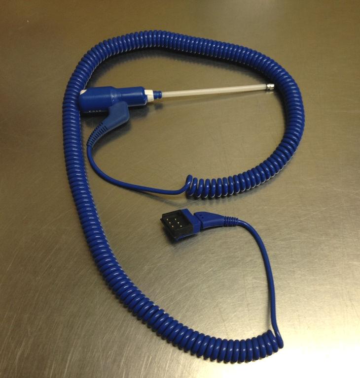
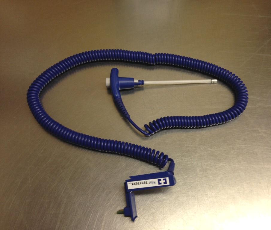
2 Old Style Parts Temperature Probe Well Probe New Style Parts Temperature Probe Well Probe


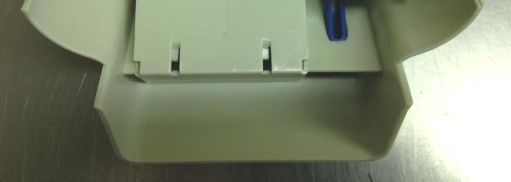
3 It is important to note that there is a distinct difference in the profiles of the older and newer temperature probe wells on the Adview diagnostic modular station. OLD NEW Thermometer module assembly Follow the steps below to assemble your new Adview probe well and temperature probe. The connector of the Temperature Probe is the portion that connects the probe itself to the probe well on the back of the device. The configuration of this probe is one of the primary differences between the new and older style temperature probes and probe wells.


4 Before you can assemble the temperature probe and the temperature module back cover, you will first need to prepare the back cover to receive the probe s connector. To begin, you will need to remove a small access plate on the rear of the cover. This component slides outwards and can be completely removed as illustrated below. This entire component can be removed to access the connection point for the thermometer probe on the back of the housing. The access plate is pulled out and away from the back cover, and is completely disconnected.

5 The thermometer probe connector is then threaded through the opening on the access plate that has just been removed. Care should be taken to ensure that the access plate is properly oriented, with the external surface of the plate facing you as the connector is inserted into the plate. The access plate must be oriented as shown to ensure that the temperature probe s connector has been inserted in the proper orientation.


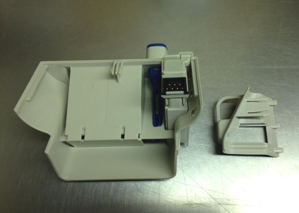
6 As shown in the image below, the connector has been threaded through the opening of the access plate and is now ready for connection to the back housing of the temperature module. The temperature probe connector has been threaded through the access plate. The connector is then connected to the port on the back of the thermometer module s back housing as shown below. The thermometer connector is inserted into the back of the temperature module housing, connecting it to this component.


7 It is important to note that the connector is held in place within the housing by a plastic tab that prevents it from coming free. The connector should be inserted until this tab clicks into place as shown below. This tab will lock into place once the connector has been fully inserted. Check the security of the probe s connector before proceeding to the next step. Once the connector is in place, the access plate can be put back in place. This component is connected using small tabs on the underside of the plate that fit into grooves on the back housing of the temperature module. Each of the tabs on the access plate have corresponding slots on the back housing of the module.


8 The complete assembly will be flush against the back housing of the temperature module and will be secure. Slide the Temperature Module Back Cover onto the Temperature Module Chassis. Use the outside rails to guide the parts into place. The top of the back cover will be flush with the top of the temperature module once the cover is pushed into place.


9 For systems with a new thermometer module installation, you may need to set the display units to F by pressing the button on the side of the module s body as shown below. Please note that the device must be powered on during this process. The button you must access is recessed into the device and is not the check button for the thermometer module. If the device is already set to Fahrenheit, this step will not be necessary. A tool will be needed to reach the recessed button. The test probe must be inserted into the well in order to change the settings from Fahrenheit to Celsius. Once the steps above have been completed, your Adview temperature module will be fully operational. This guide may be used when installing a new temperature module or when replacing worn or broken parts. For further assistance with your Adview Modular Diagnostic Station, please contact our Customer Service department toll free at ADC-2670 or visit us on the web at
CIB 3097 ESD Suppression Kit
 CIB 3097 ESD Suppression Kit CIB 3097 Comcode 105-215-321 Issue 1 CIB 3097 ESD Suppression Kit When installed in a voice terminal s ZH802A or ZH802B module that is experiencing Electro-Static Discharge
Encore XT Manual Gun Upgrade Kit
 Instruction Sheet P/N 1600823-01 Encore XT Manual Gun Upgrade Kit 1600834 Introduction Follow these instructions to upgrade your Encore manual spray gun to the improved design of the Encore XT spray gun.
Fuser. Figure Remove the fuser assembly (1 of 2) 184 Chapter 5 Removal and replacement ENWW
 184 Chapter 5 Removal and replacement ENWW") Fuser 1. Remove the following assemblies. Scanner assembly. For the HP LaserJet 3015, see Scanner assembly. For the LaserJet 3020 and 3030, see Scanner assembly. Left cover. See Printer side covers. Rear
Fuser 1. Remove the following assemblies. Scanner assembly. For the HP LaserJet 3015, see Scanner assembly. For the LaserJet 3020 and 3030, see Scanner assembly. Left cover. See Printer side covers. Rear
TABLE OF CONTENTS SECTION 1 TABLETOP CONFIGURATION SECTION 2 TABLETOP CONFIGURATION ACCESSORIES SECTION 3 SLIDE CONFIGURATION
 S6 USER S MANUAL TABLE OF CONTENTS SECTION 1 TABLETOP CONFIGURATION SECTION 2 TABLETOP CONFIGURATION ACCESSORIES SECTION 3 SLIDE CONFIGURATION SECTION 4 SLIDE CONFIGURATION ACCESSORIES SECTION 5 RACK MOUNT
OLPC XO-4 Touch Mouse Buttons Controller Replacement
 OLPC XO-4 Touch Mouse Buttons Controller Replacement This guide will show you how to replace the mouse buttons controller. Written By: Michael Kellerman ifixit CC BY-NC-SA www.ifixit.com Page 1 of 12 INTRODUCTION
AP-120 Series AP Mounting Kit
 AP-120 Series AP Mounting Kit Installation Guide The AP-120 series mounting kit provides additional mounting options for the AP-120 series wireless access points. The mounting kit includes the following
How To Install: C4000 EMV Upgrade Kit
 How To Install: C4000 EMV Upgrade Kit IMPORTANT: Before proceeding with installation please verify you have the current card reader bezel in the kit. Correct bezel will have a small eject pin hole below
Motorola Atrix 4G Bottom Speaker
 Motorola Atrix 4G Bottom Speaker Replacement This guide will show you how to access the Motorola Atrix 4Gs bottom speaker for repair or replacement. Written By: Jake ifixit CC BY-NC-SA www.ifixit.com Page
CIB 3047 (14B) 10-Button Voice Terminal Fixed Desk Stand and Wall Mount (32007)
 10-Button Voice Terminal Fixed Desk Stand and Wall Mount (32007)") CIB 3047 (14B) 10-Button Voice Terminal Fixed Desk Stand and Wall Mount (32007) CIB 3047 Comcode 845-659-325 Issue 1 CIB 3047 (14B) 10-Button Voice Terminal Fixed Desk Stand and Wall Mount (32007) This
CIB 3047 (14B) 10-Button Voice Terminal Fixed Desk Stand and Wall Mount (32007) CIB 3047 Comcode 845-659-325 Issue 1 CIB 3047 (14B) 10-Button Voice Terminal Fixed Desk Stand and Wall Mount (32007) This
OLPC XO-4 Touch Touchpad Controller Replacement
 OLPC XO-4 Touch Touchpad Controller Replacement This guide will walk through replacing a touchpad. Written By: Theodore Tsanakas ifixit CC BY-NC-SA www.ifixit.com Page 1 of 13 INTRODUCTION Use this guide
Peel/Rewind Upgrade Kit
 Peel/Rewind Upgrade Kit Installation Instructions This kit includes the parts and documentation necessary to install the Peel/Rewind upgrade kit on the following printers: ZM400 ZM600 Read these instructions
G12/G12x USER S MANUAL
 G12/G12x USER S MANUAL TABLE OF CONTENTS SECTION 1 SLIDE CONFIGURATION SECTION 2 SLIDE CONFIGURATION ACCESSORIES SECTION 3 TABLETOP CONFIGURATION SECTION 4 TABLETOP CONFIGURATION ACCESSORIES SECTION 5
How to Perform an IBM ThinkPad X60s Fan Spindle Replacement
 How to Perform an IBM ThinkPad X60s Fan Spindle Replacement This guide details an IBM ThinkPad X60s fan spindle replacement. Written By: Samuel Lees ifixit CC BY-NC-SA www.ifixit.com Page 1 of 10 INTRODUCTION
PC9/P9 CPU Card Replacement
 Introduction These instructions explain how to replace the CPU card in the PC9 Industrial PC or the P9 PowerStation. They include steps for disassembling the unit, removing the old CPU card, installing
MCH WIRE HARNESS WITH QUICK DISCONNECT REPLACEMENT Initial Release 1/31/2013
 1. Table of Contents 1. Table of Contents Page 1 2. Remove Failed MCH-103.2 Page 1 3. Install MCH-103.2 to MCH-102NW Page 2 4. Install NC3FX-HD to MCH-103.2 Page 3 5. Install MCH-103.2 Battery Terminal
Installation Note. Enhanced Memory Upgrade Kit (Option B72) for Agilent ESA-E Series and ESA-L Series Spectrum Analyzers
 for Agilent ESA-E Series and ESA-L Series Spectrum Analyzers") Installation Note Enhanced Memory Upgrade Kit (Option B72) for Agilent ESA-E Series and ESA-L Series Spectrum Analyzers Part Number E4401-90498 Supersedes: E4401-90332 Printed in USA July 2005 Notice.
Installation Note Enhanced Memory Upgrade Kit (Option B72) for Agilent ESA-E Series and ESA-L Series Spectrum Analyzers Part Number E4401-90498 Supersedes: E4401-90332 Printed in USA July 2005 Notice.
Upgrading LVDS Cables Instruction Sheet
 Upgrading LVDS Cables Instruction Sheet INTRODUCTION Use the following instructions to replace the LVDS cables in CP2000-M/MR projectors. The new cables are slightly longer in length and allow for better
LumaRail Free Stand Bed Assist Rail with IntelliBrite LED Night Light
 LumaRail Free Stand Bed Assist Rail with IntelliBrite LED Night Light Assembly and Operation Instructions Thank you for investing in this premium Platinum Health product. Please carefully follow the assembly
Welch Allyn Connex Vital Signs Monitor 6000 Power Supply Replacement
 Welch Allyn Connex Vital Signs Monitor 6000 Power Supply Replacement Replace the power supply in a 6000 series Welch Allyn Connex Vital Signs Monitor. Written By: Sam Lionheart ifixit CC BY-NC-SA www.ifixit.com
Motorola Droid X Camera Replacement
 Motorola Droid X Camera Replacement Written By: Gage ifixit CC BY-NC-SA www.ifixit.com Page 1 of 24 TOOLS: 64 Bit Driver Kit (1) ifixit Opening Tools (1) ifixit CC BY-NC-SA www.ifixit.com Page 2 of 24
LED Lighting Kit For Elara NanoEdge Fixed Frame. Installation Guide. Attention: Read this guide before assembling your screen.
 LED Lighting Kit For Elara NanoEdge Fixed Frame Installation Guide Attention: Read this guide before assembling your screen. INTRODUCTION GETTING STARTED WARNING - Sharp Edges This product may contain
MODE. Welch Allyn 767 SureTemp 4 Thermometer System. Directions For Use
 MODE Welch Allyn 767 SureTemp 4 Thermometer System Directions For Use 1995 by Diatek Instruments, Inc., A Welch Allyn Company. All rights reserved. No part of this manual may be reproduced or transmitted
Motorola Cliq LCD Screen Replacement
 Motorola Cliq LCD Screen Replacement Use this guide to replace or upgrade the LCD screen in your Motorola Cliq. Written By: Tony Tran ifixit CC BY-NC-SA www.ifixit.com Page 1 of 15 INTRODUCTION Does your
MacBook Pro 15" Core 2 Duo Models A1226 and A1260 SSD Dual Drive Installation
 MacBook Pro 15" Core 2 Duo Models A1226 and A1260 SSD Dual Drive Installation Use this guide to install a second hard drive in place of the optical drive. Written By: Dozuki System 2017 guides.crucial.com
INSIDE-OUTSIDE THERMOMETER WITH MIN/MAX MEMORY USER S MANUAL
 INSIDE-OUTSIDE THERMOMETER WITH MIN/MAX MEMORY USER S MANUAL DTR900 Please read this manual carefully and thoroughly before using this product. TABLE OF CONTENTS Introduction...................... 3 4
0. Silicon Graphics O2 and Silicon Graphics Octane R12000 CPU Upgrade Information
 0. Silicon Graphics O2 and Silicon Graphics Octane R12000 CPU Upgrade Information This booklet provides information about installing an R12000 or R12000A CPU and any necessary software in an O2 or Octane
F2A (M527) F2A (M506n/dn) F2A (M506x)
 F2A (M506n/dn) F2A (M506x)") F2A76-67910 (M527) F2A68-67915 (M506n/dn) F2A68-67916 (M506x) Lea esto primero www.hp.com/support/lj506 www.hp.com/support/ljm527mfp CAUTION: Electrostatic sensitive (ESD) parts. Always touch the sheet-metal
F2A76-67910 (M527) F2A68-67915 (M506n/dn) F2A68-67916 (M506x) Lea esto primero www.hp.com/support/lj506 www.hp.com/support/ljm527mfp CAUTION: Electrostatic sensitive (ESD) parts. Always touch the sheet-metal
MacBook Pro 15" Core 2 Duo Models A1226 and A1260 SSD Installation
 MacBook Pro 15" Core 2 Duo Models A1226 and A1260 SSD Installation Written By: Dozuki System 2017 guides.crucial.com Page 1 of 10 INTRODUCTION You can install hard drives up to 9.5mm thick. Some drive
ASSEMBLY INSTRUCTIONS for 16 WAY GT MIXED 150/280 SEALED CONNECTION SYSTEM
 ASSEMBLY INSTRUCTIONS for 16 WAY GT MIXED 150/280 SEALED CONNECTION SYSTEM NOTE: PLEASE CONTACT YOUR DELPHI SALES REPRESENTATIVE WITH ANY QUESTIONS OR COMMENTS CONCERNING THESE ASSEMBLY INSTRUCTIONS. COMPONENT
imac Intel 20" EMC 2133 and 2210 Optical Drive Data Cable Replacement
 imac Intel 20" EMC 2133 and 2210 Optical Drive Data Cable Replacement Scritto Da: Walter Galan ifixit CC BY-NC-SA it.ifixit.com Pagina 1 di 24 INTRODUZIONE Replace a broken optical drive data cable to
Further Information can be found at
 Below is a step by step guide to assembling the Hurricane-Rig. Remember that this is a precision optical instrument. Excessive force can bend critical parts. If treated well it should give many years of
imac Intel 27" EMC 2639 Hard Drive
 imac Intel 27" EMC 2639 Hard Drive Replacement Replace the Hard Drive in your imac Intel 27" EMC 2639. Written By: Walter Galan ifixit CC BY-NC-SA www.ifixit.com Page 1 of 26 INTRODUCTION Replacing the
AlphaServer DS20 Ultra SCSI Internal StorageWorks Shelf Configuration Guide
 AlphaServer DS20 Ultra SCSI Internal StorageWorks Shelf Configuration Guide Order Number: EK-H8253-IN. A01 Compaq Computer Corporation Maynard, Massachusetts First Printing, November 1998 The information
Model R2400. Instruction Manual. Digital Thermocouple Thermometer. reedinstruments
 Model R2400 Digital Thermocouple Thermometer Instruction Manual reedinstruments com 1-877-849-2127 info@reedinstruments.com.reedinstruments.com Table of Contents Safety... 2 Features... 3 Specifications...3-4
imac Intel 21.5" EMC 2428 SSD Dual Drive
 imac Intel 21.5" EMC 2428 SSD Dual Drive Installation Install an SSD in your imac Intel 21.5" EMC 2428. Written By: Dozuki System 2017 guides.crucial.com Page 1 of 33 INTRODUCTION Use this guide to install
Replacement Instructions. Backplane PCA for the HP Router 650
 Replacement Instructions Backplane PCA for the HP Router 650 Copyright Hewlett-Packard Company 1994. All rights reserved. Publication Number 5962-8369 Edition 1, August 1994 Printed in USA This guide provides
Motorola Atrix 4G Screen Replacement
 Motorola Atrix 4G Screen Replacement Replace the screen of your Motorola Atrix 4G. Written By: Jake ifixit CC BY-NC-SA www.ifixit.com Page 1 of 13 INTRODUCTION Use this guide to replace the screen of the
Replacing a Disk Drive
 Note Prior to using this procedure, verify that the seal label located on the bottom front of the unit reads, Please read HDD FRU documentation before opening. If this statement does not appear on the
Royal RVV-500 (B) Retrofit Kit
 Retrofit Kit") Optipay BV/RC/CC into a Non-Fascia Vending Machine This document contains information for installing and configuring the JCM Optipay DBV-01 Bill Validator, RC-10 Bill Recycler and A-66 Coin Changer into
Optipay BV/RC/CC into a Non-Fascia Vending Machine This document contains information for installing and configuring the JCM Optipay DBV-01 Bill Validator, RC-10 Bill Recycler and A-66 Coin Changer into
S E R V I C E N O T E
 IINFORMATIION ONLY S E R V I C E N O T E Supersedes: MSO8104A-05 MSO8104A Digitizing Oscilloscope Serial Numbers: MY00000000-MY46001900 SG00000000-SG46001900 The original scopes motherboard is no longer
Motorola Droid X Motherboard Replacement
 Motorola Droid X Motherboard Replacement Written By: Yong hoon choun ifixit CC BY-NC-SA www.ifixit.com Page 1 of 19 TOOLS: ifixit Opening Tools (1) ifixit CC BY-NC-SA www.ifixit.com Page 2 of 19 Motorola
Written By: Walter Galan
 Microsoft Zune HD OLED Display Replacement Written By: Walter Galan ifixit CC BY-NC-SA www.ifixit.com Page 1 of 15 INTRODUCTION Is your display cracked or faulty? No worries, you can replace it. TOOLS:
Procedure to Install an IO Expansion Cage Assembly in a Maxum II Modular Oven Analyzer
 Procedure to Install an IO Expansion Cage Assembly in a Maxum II Modular Oven Analyzer Difficulty Level: Medium Estimated time to execute: 1 Hour Revision History Issue Date Reason 001 5/31/2016 Initial
Mac mini Late 2014 Power Supply Replacement
 Mac mini Late 2014 Power Supply Replacement Replace the power supply in a Late 2014 Mac mini. Written By: Sam Lionheart ifixit CC BY-NC-SA www.ifixit.com Page 1 of 19 INTRODUCTION Use this guide to replace
Reflowing Xbox 360 Motherboard
 Reflowing Xbox 360 Motherboard Reflow the solder on your Xbox 360's motherboard. Written By: Andrew Bookholt ifixit CC BY-NC-SA www.ifixit.com Page 1 of 31 INTRODUCTION Use this guide to reflow the solder
Removal and Installation8
 8 Screw Types 8-4 Top Cover Assembly 8-5 Left Hand Cover 8-6 Right Hand Cover 8-10 Front Panel Assembly 8-14 Left Rear Cover 8-15 Right Rear Cover 8-16 Extension Cover (60" Model only) 8-17 Media Lever
imac Intel 20" EMC 2133 and 2210 SSD
 imac Intel 20" EMC 2133 and 2210 SSD Installation Replace the hard drive in your imac Intel 20" EMC 2133 and 2210. Written By: Dozuki System 2017 guides.crucial.com Page 1 of 16 INTRODUCTION Upgrade your
Snap Server 4400 Power Supply
 Snap Server 4400 Power Supply Snap Server 4400 Note You can set up your system to send an e-mail alert in the event of a hardware failure. For details, see the section on e-mail notification in your Administrator
TDM To MiniMech conversion ProceDure
 TDM To MiniMech conversion ProceDure (Model 9100 ATM) TDN 07102-00079 Apr 1 2009 CorporATe HeAdquArTers: 522 E. Railroad Street Long Beach, MS 39560 PHONE: (228) 868-1317 FAX: (228) 868-0437 COPYRIGHT
How to add a Second Drive to a Mac mini (2012) using the OWC Data Doubler SSD/2.5 Installation Kit
 using the OWC Data Doubler SSD/2.5 Installation Kit") Instructional Video Series How to add a Second Drive to a Mac mini (2012) using the OWC Data Doubler SSD/2.5 Installation Kit Skill Level: Challenging Time to Complete: Approximately 45 Minutes Required
Instructional Video Series How to add a Second Drive to a Mac mini (2012) using the OWC Data Doubler SSD/2.5 Installation Kit Skill Level: Challenging Time to Complete: Approximately 45 Minutes Required
Model ST-610B. Instruction Manual. Digital Thermocouple Thermometer. reedinstruments. www. com
 Model ST-610B Digital Thermocouple Thermometer Instruction Manual reedinstruments com Table of Contents Safety... 2 Features... 3 Specifications...3-4 Operating Instructions... 5 Additional Functions...
MacBook Pro 13" Unibody Mid 2010 SSD Dual Drive Installation
 MacBook Pro 13" Unibody Mid 2010 SSD Dual Drive Installation Use this guide to install a second SSD in place of the optical drive. Written By: Dozuki System 2017 guides.crucial.com Page 1 of 13 INTRODUCTION
Written By: senordingdong
 Installation of the UniMac V4 adapter into the Apple imac Intel 17". This enables the usage of non OEM LCD panels, and offers an otherwise unavailable Full HD upgrade. This used for repair of the common
MacBook Unibody Model A1278 SSD Dual Drive
 MacBook Unibody Model A1278 SSD Dual Drive Installation Use this guide to install a second hard drive in place of the optical drive. Written By: Dozuki System 2017 guides.crucial.com Page 1 of 13 INTRODUCTION
Samsung Galaxy Tab Wi-Fi Motherboard
 Samsung Galaxy Tab 4 8.0 Wi-Fi Motherboard Replacement In this guide, we will be replacing the motherboard; the main functioning component of the device. Many technical issues can be caused by a defective
Installation Guide for DV8 Off-Road Tailgate-Mounted Tire Carrier (18-19 Jeep Wrangler JL)
") Installation Guide for DV8 Off-Road Tailgate-Mounted Tire Carrier (18-19 Jeep Wrangler JL) Installation Time: 1 Hour Tools Required Trim removal tool (plastic or wood to prevent scratches on the paint)
Installation Guide for DV8 Off-Road Tailgate-Mounted Tire Carrier (18-19 Jeep Wrangler JL) Installation Time: 1 Hour Tools Required Trim removal tool (plastic or wood to prevent scratches on the paint)
Ribbon Supply Spindle Maintenance Kit
 Installation Instructions This kit includes the parts and documentation necessary to install the Ribbon Supply Spindle Maintenance Kit in the 105SL printer. Read these instructions thoroughly before installing
Replacing the SATA PCI Controller Card
 Replacing the internal controller PCI card may be performed by a single administrator; no tools are necessary. Caution There are static-sensitive electronics inside the unit. Before you handle any parts,
Dell Inspiron 1525 Upper Case Replacement
 Dell Inspiron 1525 Upper Case Replacement Replace the upper case on a Dell Inspiron 1525. Written By: Miroslav Djuric ifixit CC BY-NC-SA www.ifixit.com Page 1 of 13 INTRODUCTION Use this guide to help
Smart Multivariable Transmitter (SMV 3000) Electronics Module Replacement Kit Instruction
 Electronics Module Replacement Kit Instruction") Smart Multivariable Transmitter (SMV 3000) Electronics Module Replacement Kit Instruction Electronics Module (Part number 51404208 503, -513) Document Form: 34-SM-33-01 Effective: 09-01 Supersedes: 34-SM-33-01,
Smart Multivariable Transmitter (SMV 3000) Electronics Module Replacement Kit Instruction Electronics Module (Part number 51404208 503, -513) Document Form: 34-SM-33-01 Effective: 09-01 Supersedes: 34-SM-33-01,
Written By: Andrew Bookholt
 ipad Wi-Fi LCD Replacement Replace a broken LCD on your ipad Wi-Fi. Written By: Andrew Bookholt ifixit CC BY-NC-SA www.ifixit.com Page 1 of 14 INTRODUCTION Use this guide to replace your ipad's LCD. TOOLS:
Field-Replaceable Units
 CHAPTER 5 In order to use the Cisco Storage Series components, it is important for you to know how to correctly install and remove the plugable components. This chapter describes how to replace each of
OPERATING USER MANUAL for PRESSURE RECORDERS
 Serial No. OPERATING USER MANUAL for PRESSURE RECORDERS MNW-004 Rev. E 03/21/16 Palmer Instruments Inc. 234 Old Weaverville Road Asheville, NC 28804 Toll Free: 800-421-2853 Phone: 828-658-3131 Fax: 828-658-0728
Assembly Instructions for #5630 Medication PalWOW
 Assembly Instructions for #5630 Medication PalWOW Before assembling, please familiarize yourself with all the parts and check to make sure you have all the parts as listed below. A B A & B - The box in
Upgrade Instructions. P/N Revision A. October Printer Terminal Holder * *
 Upgrade Instructions P/N 96-08-0 Revision A October 000 480 Printer Terminal Holder P/N 96-08-0 Revision A *96080* Instructions This terminal holder connects the INTERMEC R 600 Series and 700 Series Computers
PDC / ECIS. Display Update update with conversion kit Display Update. Contents. General information. Important notes.
 US Toll Free: 800.BODE.TEC BodeTechnicalServices.com Display Update PDC / ECIS Display Update update with conversion kit 535268 Contents General information Important notes Requirements Conversion instructions
ipad Mini Wi-Fi Front Facing Camera Replacement
 ipad Mini Wi-Fi Front Facing Camera Replacement Replace the Front Facing Camera in your ipad Mini Wi-Fi. Written By: Andrew Optimus Goldberg ifixit CC BY-NC-SA www.ifixit.com Page 1 of 42 INTRODUCTION
Nikon D610 Flash Capacitor Replacement
 Nikon D610 Flash Capacitor Replacement This guide will help to show you how to replace the D610's Flash Capacitor. Written By: Daniel Eagan ifixit CC BY-NC-SA www.ifixit.com Page 1 of 10 INTRODUCTION In
MacBook Pro 15" Core 2 Duo Models A1226 and A1260 Optical Drive Replacement
 MacBook Pro 15" Core 2 Duo Models A1226 and A1260 Optical Drive Replacement Upgrade or replace the SuperDrive (requires a slim drive) in your MacBook Pro 15" Core 2 Duo Models A1226 and A1260. Written
Xbox 360 Motherboard Replacement
 Xbox 360 Motherboard Replacement Motherboard replacement. Redigido por: Walter Galan ifixit CC BY-NC-SA pt.ifixit.com Página 1 de 29 INTRODUÇÃO Use this guide to completely strip down your motherboard.
Nikon D5000 Viewfinder Replacement
 Nikon D5000 Viewfinder Replacement Disassembly down to the viewfinder hood and to the screen itself. Written By: Jacob Rardin ifixit CC BY-NC-SA www.ifixit.com Page 1 of 9 INTRODUCTION If there is dust
64-Ch Windows-based NVR. with 8-Bay Hard Disks NVR-E6480. Quick Installation Guide
 64-Ch Windows-based NVR with 8-Bay Hard Disks NVR-E6480 Quick Installation Guide Table of Contents Before You Start... 3 Package Contents... 4 1. Hardware Introductions... 5 1.1 Physical Details... 5 1.2
Rack Installation Instructions
 Rack Installation Instructions Review the documentation that comes with your rack cabinet for safety and cabling information. When installing your server in a rack cabinet, consider the following: v Two
IBM. Rack Installation Instructions
 IBM Rack Installation Instructions Review the documentation that comes with your rack cabinet for safety and cabling information. When installing your server in a rack cabinet, consider the following:
E2460GS Oscilloscope Upgrade Kit
 Installation Instructions for E2460GS Oscilloscope Upgrade Kit Agilent 1670G-Series Logic Analyzers This kit upgrades either the Agilent Technologies 1670G, Agilent 1671G, Agilent 1672G, or the Agilent
Apple 3.5 Drive External Floppy Drive
 Apple 3.5 Drive External Floppy Drive Teardown This guide will show the disassembly down to the bare internal drive and other components of the Apple 3.5 Drive. Written By: rockinkat ifixit CC BY-NC-SA
SCXI-1345 Shielded Cable
 NATIONAL INSTRUMENTS The Software is the Instrument Installation Guide SCXI-1345 This guide describes how to install the SCXI-1345 shielded cable with an adapter board between an SCXI module and a data
Written By: Miroslav Djuric
 ipad Wi-Fi Speakers Replacement Replace your ipad Wi-Fi's speaker assembly. Written By: Miroslav Djuric ifixit CC BY-NC-SA www.ifixit.com Page 1 of 13 INTRODUCTION Replace the speaker assembly and restore
HP C8000 Workstation Disassembly Procedures
 HP C8000 Workstation Disassembly Procedures 410892-001 November, 2005 Edition 1 PRODUCT END-OF-LIFE DISASSEMBLY INSTRUCTIONS... 2 1.1 Product Identification...2 1.2 Purpose...2 1.3 Removal Items...2 1.4
Replacing Preamplifier Circuit Boards
 Instruction Guide Replacing Preamplifier Circuit Boards Before you begin This instruction sheet applies to the Plexon PBX-series preamplifiers. Use these instructions to expand, replace, or upgrade the
UNITY 2 TM. With ULTRA (50:50) & Air Server Series 2. Version 1.2. September 2012
 & Air Server Series 2. Version 1.2. September 2012") UNITY 2 TM With (50:50) & Air Server Series 2 Version 1.2 September 2012 1. Installation for an system...2 2. Switching between & Air Server...4 3. 50:50 with UNITY 2 and Air Server series 2...8 4. Switching
UNITY 2 TM With (50:50) & Air Server Series 2 Version 1.2 September 2012 1. Installation for an system...2 2. Switching between & Air Server...4 3. 50:50 with UNITY 2 and Air Server series 2...8 4. Switching
imac Intel 27" Retina 5K Display CPU Replacement
 imac Intel 27" Retina 5K Display CPU Replacement Replace or upgrade the CPU in your imac Intel 27" Retina 5K Display. Written By: Sam Lionheart ifixit CC BY-NC-SA www.ifixit.com Page 1 of 36 INTRODUCTION
HP TouchPad USB Connector Board Replacement
 HP TouchPad USB Connector Board Replacement Replace the USB connector board on your HP TouchPad. Written By: Andrew Bookholt ifixit CC BY-NC-SA www.ifixit.com Page 1 of 12 INTRODUCTION Use this guide to
Sonnet AV/HPV Card Video Adapter Kit
 Installation Instructions for Power Macintosh 7100 and 8100 Adapter Kit Inventory Before installing the AV/HPV Card Video Adapter, you will require the following items (Figure 1): Included with adapter
imac Intel 21.5" EMC 2389 Stand Replacement
 imac Intel 21.5" EMC 2389 Stand Replacement Replace a broken or cosmetically unappealing stand on the imac 2389 21.5 Written By: Aaron Cooke ifixit CC BY-NC-SA www.ifixit.com Page 1 of 30 INTRODUCTION
iphone 6 Plus Front Facing Camera and Sensor Assembly Replacement
 iphone 6 Plus Front Facing Camera and Sensor Assembly Replacement Replace the Front-Facing Camera and Sensor Assembly in your iphone 6 Plus. Written By: Walter Galan ifixit CC BY-NC-SA www.ifixit.com Page
Universal Desktop and Monitor Stand
 Universal Desktop and Monitor Stand Installation Instructions Kit P/N: 114-6013 Kit Contents Kit Contents: (1) Stand Assembly (1) VESA Monitor Bracket (1) Bottom Bracket (1) Top Bracket (1) Clamp Bracket
imac Intel 24" EMC 2134 and 2211 Hard Drive
 imac Intel 24" EMC 2134 and 2211 Hard Drive Replacement Replace the hard drive in your imac Intel 24" EMC 2134 and 2211. Written By: Brittany McCrigler ifixit CC BY-NC-SA www.ifixit.com Page 1 of 18 INTRODUCTION
3 1 ROM. Installation Manual
 3 1 ROM Installation Manual 3.1 ROM Installation Instructions Please read the following cartfully The following installation sequences should be performed by an authorised Amiga Technologies service centre,
TDM-100/150 TO NMD-50 CONVERSION PROCEDURES RL5000
 TDM-00/50 TO NMD-50 CONVERSION PROCEDURES RL5000 TDN 0702-00062 March 7, 204 Corporate Headquarters 2405 B Street Long Beach, MS. 39560 Phone: (800) 259-6672 Fax: (228) 868-9445 COPYRIGHT NOTICE 204 Triton.
(Hardware and case keys are provided inside the chassis storage compartment.)
") 1. Motherboard installation...1 2. Install 3½ and 5¼ drives...3 3. Install PCI components...4 4. Fan installation and setup...5 5. Temperature probe setup...6 6. Connect case leads to motherboard...7 7.
1. Motherboard installation...1 2. Install 3½ and 5¼ drives...3 3. Install PCI components...4 4. Fan installation and setup...5 5. Temperature probe setup...6 6. Connect case leads to motherboard...7 7.
Indoor Protected Entrance Terminal 4588 Series
 Indoor Protected Entrance Terminal 4588 Series Instructions Underwriters Laboratories (UL) Listed September 2003 78-8135-1209-8-A 1.0 General The 3M Indoor Protected Entrance Terminal (PET) 4588 Series
INSTALLATION INSTRUCTIONS
 TT-40 9/0 INSTALLATION INSTRUCTIONS Original Issue Date: 9/0 Model: Automatic Transfer Switches Equipped with the Programmable Controller Market: ATS Subject: External Battery Supply Module Kit GM69-KP
RACKMOUNT CONSOLE KVM SWITCH QUICK INSTALLATION GUIDE
 RACKMOUNT CONSOLE KVM SWITCH QUICK INSTALLATION GUIDE MODELS 521796, 521871, 523561 & 523578 INT-521796/521871/523561/523578-QIG-0307-01 INTRODUCTION Thank you for purchasing the INTELLINET NETWORK SOLUTIONS
BCM Rls 6.0. Redundancy. Task Based Guide
 BCM Rls 6.0 Redundancy Task Based Guide Copyright 2010 Avaya Inc. All Rights Reserved. Notices While reasonable efforts have been made to ensure that the information in this document is complete and accurate
ipad Mini 2 Wi-Fi Front Panel Assembly Replacement
 ipad Mini 2 Wi-Fi Front Panel Assembly Replacement Fix a broken ipad Mini 2 screen. Replace the front glass and digitizer on an ipad Mini 2 Wi-Fi. Written By: Sam Lionheart ifixit CC BY-NC-SA www.ifixit.com
PlayStation 3 Teardown PS3. Written By: Mint137. ifixit CC BY-NC-SA Page 1 of 22
 PlayStation 3 Teardown PS3 Written By: Mint137 ifixit CC BY-NC-SA www.ifixit.com Page 1 of 22 INTRODUCTION This is a teardown of an original launch 60GB PlayStation 3 system. One of the best units out
Written By: Miroslav Djuric
 Written By: Miroslav Djuric ifixit CC BY-NC-SA www.ifixit.com Page 1 of 10 INTRODUCTION This guide shows how to open the original iphone. TOOLS: Probe and Pick Set (1) SIM Card Eject Tool (1) Metal Spudger
1500SE UPGRADE DOCUMENT
 1500SE UPGRADE DOCUMENT Version 1.03 September 4, 2014 2014 Nautilus Hyosung, Inc. All Rights Reserved. Table of Contents Overview... 1 Installation Procedures... 1 1. Unlock and Open the Front Panel...
iphone 1st Generation Camera Replacement Written By: irobot ifixit CC BY-NC-SA Page 1 of 11
 Written By: irobot ifixit CC BY-NC-SA www.ifixit.com Page 1 of 11 INTRODUCTION Want to replace or take out the camera or your employer requires it? Here's how. TOOLS: Probe and Pick Set (1) SIM Card Eject