Analyzer/Controller. ph/orp HART. Model 54e ph/orp ESSENTIAL INSTRUCTIONS WARNINGS RISK OF ELECTRICAL SHOCK
|
|
|
- Madeleine Glenn
- 6 years ago
- Views:
Transcription
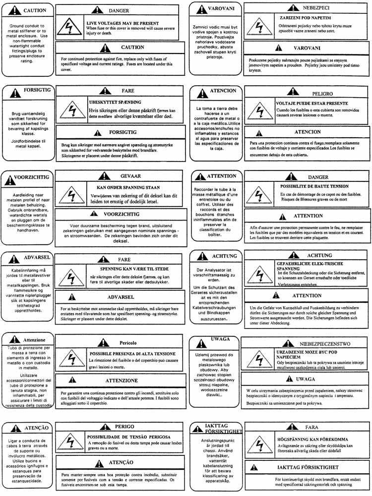
1 Instruction Sheet PN 51A-54epH/rev J October 2010 ph/orp HART Model 54e ph/orp Analyzer/Controller For additional information, please visit our website at ESSENTIAL INSTRUCTIONS READ THIS PAGE BEFORE PROCEEDING! Rosemount Analytical designs, manufactures, and tests its products to meet many national and international standards. Because these instruments are sophisticated technical products, you must properly install, use, and maintain them to ensure they continue to operate within their normal specifications. The following instructions must be adhered to and integrated into your safety program when installing, using, and maintaining Rosemount Analytical products. Failure to follow the proper instructions may cause any one of the following situations to occur: Loss of life; personal injury; property damage; damage to this instrument; and warranty invalidation. Read all instructions prior to installing, operating, and servicing the product. If this Instruction Manual is not the correct manual, telephone and the requested manual will be provided. Save this Instruction Manual for future reference. If you do not understand any of the instructions, contact your Rosemount representative for clarification. Follow all warnings, cautions, and instructions marked on and supplied with the product. Inform and educate your personnel in the proper installation, operation, and maintenance of the product. Install your equipment as specified in the Installation Instructions of the appropriate Instruction Manual and per applicable local and national codes. Connect all products to the proper electrical and pressure sources. To ensure proper performance, use qualified personnel to install, operate, update, program, and maintain the product. When replacement parts are required, ensure that qualified people use replacement parts specified by Rosemount. Unauthorized parts and procedures can affect the product s performance and place the safe operation of your process at risk. Look alike substitutions may result in fire, electrical hazards, or improper operation. Ensure that all equipment doors are closed and protective covers are in place, except when maintenance is being performed by qualified persons, to prevent electrical shock and personal injury. WARNINGS RISK OF ELECTRICAL SHOCK Making cable connections to and servicing this instrument require access to shock hazard level voltages which can cause death or serious injury, therefore, disconnect all hazardous voltage before accessing the electronics. Relay contacts made to separate power sources must be disconnected before servicing. Electrical installation must be in accordance with the National Electrical Code (ANSI/NFPA-70) and/or any other applicable national or local codes. Unused cable conduit entries must be securely sealed by non-flammable closures to provide enclosure integrity in compliance with personal safety and environmental protection requirements. Use NEMA 4X or IP65 conduit plugs supplied with the instrument to maintain the ingress protection rating (IP65). For safety and proper performance this instrument must be connected to a properly grounded threewire power source. Proper relay use and configuration is the responsibility of the user. No external connection to the instrument of more than 60VDC or 43V peak allowed with the exception of power and relay terminals. Any violation will impair the safety protection provided. Do not operate this instrument without front cover secured. Refer installation, operation and servicing to qualified personnel. WARNING This product is not intended for use in the residential, commercial or light industrial environment per certification to EN
2
3 SPECIFICATIONS PHYSICAL SPECIFICATIONS GENERAL Enclosure: Epoxy-painted aluminum NEMA 4X (IP65) 144 X 144 X 131 mm, DIN size (5.7 X 5.7 X 5.2 in.) Front Panel: Membrane keyboard with tactile feedback and user selectable security. Light gray, blue and white overlay Light gray enclosure, dark gray bezel Display: Back-lit dot matrix LCD (7.0 x 3.5 cm), blue on gray-green The display contrast is compensated for ambient temperature. Process Variable Character Height: 16mm (0.6 in.) Electrical Classification: Class I, Division 2, Groups A, B, C, & D. T5 Ta=50 C. Dust ignition proof: Class II, Division 1, Groups E, F, & G; Class III. CSA-LR34186: Max. relay contact rating: 28 Vdc; 110 Vac; 230 Vac; 6 amps resistive FM: Max. relay contact rating: 28 Vdc resistive 150 ma - Groups A & B; 400 ma - Group C; 540 ma - Group D Power: Code -01: VAC, 50/60 Hz ± 6%, 6.0 W VAC, 50/60 Hz ± 6%, 6.0 W Code -02: VDC, 6.0 W Current Outputs: Output 1: ph, ORP, temperature, glass impedance, or reference impedance. Output 2: ph, ORP, temperature, glass impedance, or reference impedance. Each output is galvanically isolated, 0-20 ma or 4-20 ma into 500 ohms maximum load at 24 Vdc or 115/230 Vac or 500 ohms maximum load at 100/200 Vac. Output 1 includes digital signal 4-20 ma superimposed HART (Code -09 only). RFI/EMI: EN LVD (Code -01 only): EN Sira MC070111/00 Ambient Temperature: 0 to 50 C (32 to 122 F) NOTE: The analyzer is operable from -20 to 60 C (-4 to 140 F) performance. Relative Humidity: 95%, non condensing Alarms: Relay 1 - Process, Interval, or Time Proportional Control (TPC requires code -20) Relay 2 - Process, Interval, or Time Proportional Control (TPC requires code -20) Relay 3 - Process, Interval, or Time Proportional Control (TPC requires code -20) Relay 4 - Sensor/analyzer and process fault alarm Each relay has a dedicated LED on the front panel. Relay Contacts: Relays 1-3: Epoxy sealed form A contacts, SPST, normally open Relay 4: Epoxy sealed form C, SPDT Resistive Inductive 28 Vdc 5.0 Amps 3.0 Amps 115 Vac 5.0 Amps 3.0 Amps 230 Vac 5.0 Amps 1.5 Amps Weight/Shipping Weight: 1.8 kg/2.3 kg (4 lb/5 lb) INSTRUMENT 25 C ph Measurement Range: 0 to 14 ph Output Scale Expansion: Zero suppression: up to 13 ph units Span: Any ph from 1 to 14 Accuracy: ± 0.01 ph Repeatability: ± 0.01 ph Stability: ± 0.01 ph/month, non-cumulative Temperature Coefficient: Input: ± ph/ C Output: ± ph/ C Temperature Compensation: Pt 100 or Pt 1000 RTD, Automatic or Manual; 15 to 120 C (5 to 248 F) INSTRUMENT 25 C ORP Measurement Range: 1400 to mv Output Scale Expansion: Zero suppression: up to ±1300 mv Span: Any ORP range from 100 to 2800 mv Accuracy: ± 1.0 mv Repeatability: ± 1.0 mv Stability: ± 1.0 mv/month, non-cumulative Temperature Coefficient: Input: ± 0.2 mv/ C Output: ± 0.4 mv/ C Temperature Measurement: 15 to 120 C (5 to 248 F) Pt 100 or Pt 1000 RTD 3
4 INSTALLATION WARNING All electrical installation must conform to the National Electrical Code, all state and local codes, and all plant codes and standards for electrical equipment. All electrical installations must be supervised by a qualified and responsible plant electrician. LOCATING THE CONTROLLER Position the Model 54e ph/orp controller to minimize the effects of temperature extremes and to avoid vibration and shock. Locate the controller away from your chemical process to protect it from moisture and fumes. Select an installation site that is more than 2 ft from high voltage conduit, has easy access for operating personnel, and is not exposed to direct sunlight. UNPACKING AND INSPECTION Inspect the exterior of the shipping container for any damage. Open the container and inspect the controller and related hardware for missing or damaged parts. If there is evidence of damage, notify the carrier immediately. If parts are missing, contact Rosemount Analytical customer support. Pipe Mounting: 1. Attach the mounting bracket to the rear of the controller and tighten the four screws. 2. Place supplied U bolts around the mounting pipe and through the pipe mounting bracket and mounting bracket. Tighten the U bolt nuts until the controller is securely mounted to the pipe. Panel Mounting: The controller is designed to fit into a 5.43 x 5.43 inch (DIN standard 144x144 mm) panel cutout (shown below). Installation requires both front and rear access. 1. Install the controller as shown below. Insert the instrument enclosure through the front of the panel cutout and align the panel mounting brackets as shown. 2. Insert two mounting bracket screws through each of the two mounting brackets and into the tapped holes in the rear of the controller enclosure and tighten each screw. 3. Insert four panel mounting screws through each hole in the mounting brackets. Tighten each screw until the mounting bracket holds controller firmly in place. To avoid damaging the controller mounting brackets, do not use excessive force. MECHANICAL INSTALLATION Mounting the Controller The Model 54e ph/orp controller may be supplied with a mounting bracket accessory. If you use the mounting bracket on wall or pipe installations, avoid mounting on pipes which vibrate or are close to the process. The bracket may be modified to mount the controller on I-beams or other rigid members. You can also fabricate your own bracket or panel mount the controller using the bracket as an example. Wall or Surface Mounting: 1. Mount the bracket to the controller using the supplied four screws. 2. Mount controller mounting bracket to wall using any appropriate fastener such as screws, bolts, etc PANEL MOUNTING 4 WALL MOUNTING PIPE MOUNTING
5 MENUS All menus shown. Some menus will change or not appear with different settings. 5
6 QUICK START MODEL 54e ph/orp QUICK START Use the or key to move the cursor down or up and the or to move the cursor right or left. Press ENTER (F4) to move to the next menu, SAVE (F4) to store a setting, EDIT (F4) to change a setting, and EXIT (F1) to exit without saving changes. STEP 1 - MEASUREMENT TYPE Note: The analyzer is factory configured for a ph sensor. Skip to step 2 if you will be measuring ph. Press any button. he main menu will appear with CALI- BRATE highlighted. Use the arrow buttons to select Program. Press Use the arrow buttons to select Configure. Press DISPLAY will be highlighted. Press MEASURE will be highlighted. Press Use the arrow buttons to select REDOX or ORP. Press SAVE. Press EXIT until the main display appears. STEP 2 - OUTPUT SETPOINTS Press any button. The main menu will appear with CAL- IBRATE highlighted. Use the arrow buttons to select Program. Press Use the arrow buttons to select OUTPUT SETPOINTS. Press OUTPUT 1 SETPOINTS will be highlighted. Press Press CONT. 4 ma will be highlighted. Press EDIT. Use the arrow buttons to enter the desired value. Press SAVE. Use the arrow buttons to select 20 MA. Press EDIT. Use the arrow buttons to enter the desired value. Press SAVE. Press EXIT. Use the arrow buttons to select OUTPUT 2 SET- POINTS. Press Press CONT. Enter the 4 ma and 20 ma values as above. Press EXIT until the main display appears. STEP 3 - AUTOCAL Note: Obtain two ph buffer solutions with values at least 2 ph units apart. (Factory set buffers are 4.01, 7.00, and ph.) Press any button. The main menu will appear with CAL- IBRATE highlighted. Press BUFFER CALIBRATION will be highlighted. Press Place the sensor in the first buffer and press CONT. Wait until the screen reads "Buf 1 done." Use the arrow buttons to select the correct buffer. Press CONT. Rinse and dry the sensor. Place the sensor in the second buffer and press CONT. Wait until the screen reads "Buf 2 done." Use the arrow buttons to select the correct buffer. Press CONT. Press EXIT until the main display appears. STEP 4 - SINGLE-POINT STANDARDIZATION After the sensor is installed, take a grab sample as close to the sensor as possible. Use a calibrated ph instrument with automatic temperature compensation to determine the ph of the grab sample. Press any button. The main menu will appear with CAL- IBRATE highlighted. Press Use the arrow buttons to select STANDARDIZE. Press Press EDIT. Use the arrow buttons to enter the ph value of the sample. Press SAVE. Press EXIT until the main display appears. 6
7 WIRING Sensor Wiring Diagram 7


 757-8500 Fax: (949)")
8 Power Input and Relay Output Wiring for Model 54e ph/orp The right people, the right answers, right now. ON-LINE ORDERING NOW AVAILABLE ON OUR WEB SITE Specifications subject to change without notice. 8 Credit Cards for U.S. Purchases Only. Emerson Process Management 2400 Barranca Parkway Irvine, CA USA Tel: (949) Fax: (949) Rosemount Analytical Inc. 2010
Instruction Sheet PN 51A-6081C/rev.A June Model 6081-C Wireless Contacting Conductivity Transmitter
 Instruction Sheet PN 51A-6081C/rev.A June 2009 Model 6081-C Wireless Contacting Conductivity Transmitter ESSENTIAL INSTRUCTIONS READ THIS PAGE BEFORE PROCEEDING! Rosemount Analytical designs, manufactures,
5450 NW 33rd Ave, Suite 104 Fort Lauderdale, FL Fruitland Ave Los Angeles, CA SST7000 SST7100. Speed Switch / Transmitter
 5450 NW 33rd Ave, Suite 104 Fort Lauderdale, FL 33309 3211 Fruitland Ave Los Angeles, CA 90058 SST7000 SST7100 Speed Switch / Transmitter Installation and Operation Manual Rev. C P/N145F-13112 PCO 00009270
INSTRUCTION MANUAL. Universal AC Input Switching Power Supply 24 Vdc Output DIN-Rail Models PSD1000, PSD1000F PSD PSD1000F
 PSD1000 - PSD1000F INSTRUCTION MANUAL Universal AC Input Switching Power Supply 24 Vdc Output DIN-Rail Models PSD1000, PSD1000F PSD1000 - Universal AC Input Switching Power Supply 24 Vdc Output ISM0089-4
+GF+ SIGNET ph/orp Transmitter Instructions
 GF SIGNET 8750 ph/orp Transmitter Instructions ENGLISH 8750.090 A9/99 English CAUTION! Remove power to unit before wiring input and output connections. Follow instructions carefully to avoid personal injury.
Analyze IT Analytical Instruments Two-Wire ph, ORP, plon Transmitters
 Data Sheet D-NPA-TB82PH_2 Analyze IT Analytical Instruments Two-Wire ph, ORP, plon Transmitters Model TB82PH Series Designed With the Real World in Mind Easy to use menus guide the operator through set-up,
ORB TM 4-20 ma Input Box Installation & Operation Manual
 IOM ORB TM 4-20 ma Input Box Installation & Operation Manual ORB TM 4-20 ma Input Box Installation & Operation Manual CONTENTS I. HANDLING & STORAGE... 1 Inspection and Handling Disposal and Recycling
Model HU-224/225. Technical Information TI.224/ Humidity Transduce r FOR ADDITIONAL INFORMATION SEE HU-224/225 DATA SHEET
 Model /225 FOR ADDITIONAL INFORMATION SEE /225 DATA SHEET SPECIFICATIONS Accuracy*: ± 2% / ± 3% RH Range: 0-100% RH Hysteresis: ± 1% Supply Voltage:12-40 VDC 12-35 VAC (VDC output units only) Supply Current:
1/32-DIN TEMPERATURE CONTROLLER INSTALLATION, WIRING AND OPERATION MANUAL FORM 3882
 1/32-DIN TEMPERATURE CONTROLLER INSTALLATION, WIRING AND OPERATION MANUAL FORM 3882 This manual is intended for use in support of installation, commissioning and configuration of the 1/32-DIN Temperature
Tempco Instruction Manual
 Tempco Instruction Manual 1/16 DIN Solid State Temperature Controller Relay Output Solid State Output For Heating Model Numbers: TEC-901, TEC-902, TEC-905 Temperature controls in this series are designed
5450 NW 33rd Ave, Suite 104 Fort Lauderdale, FL Fruitland Ave Los Angeles, CA UM Channel Monitor.
 5450 NW 33rd Ave, Suite 104 Fort Lauderdale, FL 33309 3211 Fruitland Ave Los Angeles, CA 90058 UM-600 6-Channel Monitor Version 2 Installation and Operation Manual Rev. G P/N145F-12990 PCO 00007462 (c)
General Purpose ph/orp Sensor
 Instruction Sheet PN 51A-399VP/rev.J January 2011 Model 399VP General Purpose ph/orp Sensor SPECIFICATIONS Sensor Type: General purpose 399VP Measured Range: ph: ACCUGLASS 0-14 ORP: -1500 to +1500 mv Percent
CDD Carbon Dioxide Transmitter
 Introduction The OSA CO2 transmitter uses Infrared Technology to monitor CO2 levels within a range of 0 2000 ppm and outputs a linear 4-20 ma or 0-5/0-10 Vdc signal. The enclosure is designed to operate
Analytical Instruments Two-Wire ph, ORP, plon Transmitters
 Data Sheet Analytical Instruments Two-Wire ph, ORP, plon Transmitters Model TB82PH Series Designed With the Real World in Mind Easy to use menus guide the operator through set-up, calibration and maintenance
6-Channel Monitor. Installation and Operation Manual
 3211 Fruitland Ave Los Angeles, CA 90058 Catalyst Monitor 6-Channel Monitor Version 2 Installation and Operation Manual Rev. H P/N145F-12964 PCO - 00009743 (c) Copyright 2015, Barksdale, Inc. All Rights
MTII4200 Level Transmitter Installation, Operation & Maintenance Instructions
 Specialists in Liquid Level Indication MTII4200 Level Transmitter Installation, Operation & Maintenance Instructions Section: M500 Bulletin: M500.31 Date: 05-17-16 Supersedes: 09-30-11 1. INTRODUCTION
ABB MEASUREMENT & ANALYTICS DATA SHEET. TB84PH ph /ORP / pion transmitter
 ABB MEASUREMENT & ANALYTICS DATA SHEET TB84PH ph /ORP / pion transmitter 2 TB 8 4PH P H /ORP / P I ON TR AN S MIT TE R DS/ TB8 4PH-E N RE V. D Measurement made easy Hazardous area rated transmitter with
TPE 1464 Series Pressure Transducer
 TPE 1464 Series Pressure Transducer Description The KMC TPE 1464 series of pressure transducers incorporate a gauge pressure transmitter featuring low hysteresis, excellent repeatability, and longterm
Model T28 Transmitter
 Model T28 Transmitter Product Training Presented by: Joe Bradley October 2009 ELECTRO-CHEMICAL DEVICES Model T28 Transmitter Two Wire Transmitter Loop Powered 24 VDC @ 500 Ω Measurement Choices ph ORP
Operating Instructions. Isolation Relay for Switches Model: RL manual_rl-6100_1116
 Operating Instructions Isolation Relay for Switches Model: RL-6100 1. Contents 1. Contents...2 2. Note...3 3. Instrument Inspection...3 4. Regulation Use...3 5. Operating Principle...4 6. Mechanical Connection...4
Cole-Parmer Instrument Company
 Operating Instructions Cole-Parmer ph/orp 400 ph/orp Controller Cole-Parmer Instrument Company 625 East Bunker Court, Vernon Hills, Illinois 60061 Tel: 1-847-549-7600 or Toll-free: 1-800-323-4340 Fax:
FOUNDATION Fieldbus Two-Wire Conductivity Transmitter
 Instruction Sheet PN 51A-5081T-FF/rev.E March 2004 Model 5081T-FF FOUNDATION Fieldbus Two-Wire Conductivity Transmitter Your purchase from Rosemount Analytical, Inc. has resulted in one of the finest instruments
Operation Manual MODEL 2TX. 2-wire Isolated ph/orp Transmitter
 Operation Manual MODEL 2TX 2-wire Isolated ph/orp Transmitter 0 2TX CONTENTS INITIAL INSPECTION.....2 INTRODUCTION......2 ASSEMBLY...3 PREPARATION....4 CONNECTING THE ELECTRODE...4 CONNECTING THE TEMPERATURE
Operating Instructions. Intrinsically Safe Isolation Relay for Switches Model: REL manual_rel-6_0505
 Operating Instructions Intrinsically Safe Isolation Relay for Switches Model: REL-6003 manual_rel-6_0505 1. Contents 1. Contents...2 2. Note...3 3. Instrument Inspection...3 4. Regulation Use...3 5. Operating
General-Purpose Photoelectric Sensor
 General-Purpose Photoelectric Sensor Compact Limit Switch Style with Universal Supply FET output allows for solid state switching of AC or DC Universal AC/DC power supply Choose cable or connector types
SP6R Level Controller Operation Manual
 SP6R Level Controller Operation Manual www.sjerhombus.com SP6R LEVEL CONTROLLER INTRODUCTION SJE-Rhombus, an industry leader in water and wastewater pump controls, introduces the SP6R Level Controller.
Operating Instructions. Power Supply & Isolation Relay for Switches Model: RL manual_rl-5900_0215
 Operating Instructions Power Supply & Isolation Relay for Switches Model: RL-5900 manual_rl-5900_0215 1. Contents 1. Contents...2 2. Note...3 3. Instrument Inspection...3 4. Regulation Use...3 5. Operating
OPERATION MANUAL MODEL TT-LP
 TURTLE TOUGH OPERATION MANUAL MODEL TT-LP 2-Wire Isolated ph/orp Transmitter turtletough.com.au CONTENT INITIAL INSPECTION 3 INTRODUCTION 3 ASSEMBLY 4 PREPARATION 5 Connection Diagram of Turtle Tough Sensors
Table of Contents. General Information. Document Sure-Aire Flow Monitoring System. User and Service Manual WARNING CAUTION
 Document 476092 User and Service Manual Installation, Operation and Maintenance Manual Please read and save these instructions for future reference. Read carefully before attempting to assemble, install,
SIGNET 5700 ph/orp Monitor - ORP Instructions
 SIGNET 5700 ph/orp Monitor ORP Instructions ENGLISH 35700.0901 H (6/01) English CAUTION! Refer to instruction manual for more details. Remove power to unit before wiring input and output connections. Follow
SX90 Process Controller
 Local regulations may restrict the use of this product to below the conditions quoted. In the interests of development and improvement of the product, we reserve the right to change the specification without
CDD4 Duct Carbon Dioxide Transmitter
 Drill or punch a 1-1/8 or 1-1/4 hole in the duct at the preferred location and insert the probe into the hole to mark the enclosure mounting holes. Remove the unit and drill the four mounting holes. Clean
UDC 1000 and UDC 1500 MICRO-PRO SERIES UNIVERSAL DIGITAL CONTROLLERS
 UDC 1000 and UDC 1500 MICRO-PRO SERIES UNIVERSAL DIGITAL CONTROLLERS EN0I-6041 12/99 PRODUCT SPECIFICATION SHEET OVERVIEW The UDC 1000 and UDC 1500 are microprocessor-based 1/16 DIN and 1/8 DIN controllers
MYRIAD QLC 4-CHANNEL MONITOR/CONTROLLER INSTRUCTION MANUAL
 MYRIAD QLC 4-CHANNEL MONITOR/CONTROLLER INSTRUCTION MANUAL VISIT OUR WEBSITE SIGMACONTROLS.COM MYR QLC MANUAL 013114 2 TABLE OF CONTENTS INTRODUCTION 3 Ordering Information Specifications Features WIRING
Contents. 1. Installation
 ENGLISH 8750.090 C/0 English CAUTION! Remove power to unit before wiring input and output connections. Follow instructions carefully to avoid personal injury. Contents. Installation. Specifications. Electrical
Large DIspLay process Meters
 Large DIspLay process Meters Model pd650 NeMa 4X 2.3" High LeD Model pd655 NeMa 4X 1.0" High LeD Model pd656 exp-proof 4X 0.8" High LeD 4-20 ma, 1-5 V, 0-5 V, 0-10 V inputs 4½ digit + extra zero display
Level-Lance Model 5400A
 Sales Manual Section 100 PRODUCT SPECIFICATION 5400A GENERAL DESCRIPTION The ROBERTSHAW Level-Lance Model 5400A is a microprocessor based, multi-point On-Off capacitance type level detection system. Utilizing
INSTRUCTION MANUAL. SIL 3 Relay Output Module DIN-Rail Models D1092S-069, D1092D-069 D1092S D1092D-069
 D09S09 D09D09 INSTRUCTION MANUAL SIL Relay Output Module DINRail Models D09S09, D09D09 D0909 SIL Relay Output Module ISM00 SIL Applications For Safety Related System and SIL, SIL Applications according
Instruction Manual. M Pump Motor Controller. For file reference, please record the following data:
 Instruction Manual M Pump Motor Controller For file reference, please record the following data: Model No: Serial No: Installation Date: Installation Location: When ordering replacement parts for your
Dräger Polytron 8200 Stationary gas detector (CatEx)
") Dräger Polytron 8200 Stationary gas detector (CatEx) Quick, reliable and cost-effective detection of combustible gases and vapours in the ambient air: the microprocessor-based transmitter is the result
Dräger Polytron 8200 Stationary gas detector (CatEx) Quick, reliable and cost-effective detection of combustible gases and vapours in the ambient air: the microprocessor-based transmitter is the result
Carbon Monoxide (CO) Gas Detection and Control System
 Gas Detection and Control System") Carbon Monoxide (CO) Gas Detection and Control System DESCRIPTION Gas monitor with built-in carbon monoxide (CO) sensor, wall-mounted, accepts inputs from remote devices such as other gas sensors, temperature
Carbon Monoxide (CO) Gas Detection and Control System DESCRIPTION Gas monitor with built-in carbon monoxide (CO) sensor, wall-mounted, accepts inputs from remote devices such as other gas sensors, temperature
Operating instructions. Speed monitor D / / 2014
 Operating instructions Speed monitor D200 80005257 / 00 05 / 2014 Contents 1 Preliminary note...4 1.1 Symbols used...4 1.2 Warning signs used...4 2 Safety instructions...5 2.1 General...5 2.2 Target group...5
MODCELL 2050R Single Loop Controllers
 Isolated universal process and remote set-point input Four internal set-points No jumpers required to define instrument parameters Ratio/bias on process and remote set-point Totalizer Ramp/soak profile
CDD4 Series Room CO2 Transmitter Installation Instructions
 CDD4 Series Room CO2 Transmitter Installation Instructions Introduction The CO2 transmitter uses Infrared Technology to monitor CO2 levels and outputs a linear 4-20 ma or 0-5/0-10 Vdc signal. Options include
Operating Manual LF1-LF4 i
 Operating Manual Oct. 2005 Fillerkampsweg 1 5 31832 Springe OT Eldagsen Tel.: 05044/887-0 (Fax: -99) E-Mail: info@iotronic.de Internet: http://www.iotronic.de Page 3 Contents 1.0 General Guidelines for
BXD17 Series. Features. Analytical instrumentation for your measurement applications.
 BXD17 Series Analytical instrumentation for your measurement applications. Features Single parameter instrument with temperature measurement capabilities Custom IP66 NEMA 4X (144 x 144mm) enclosure Versatile
Operating instructions. Switching amplifier DN0210 DN / / 2015
 Operating instructions Switching amplifier DN0210 DN0220 UK 80011079 / 00 01 / 2015 Contents 1 Preliminary note...4 1.1 Symbols used...4 1.2 Warning signs used...4 2 Safety instructions...5 2.1 General...5
TABLE OF CONTENTS TABLE OF CONTENTS... 1 IMPORTANT SAFETY NOTICE...
 TABLE OF CONTENTS TABLE OF CONTENTS... 1 IMPORTANT SAFETY NOTICE... 2 1.0 General Information... 3 1.1 System Components... 3 1.2 Specifications... 3 1.2.1 Torque Ranges... 3 1.2.2 Electrical Specifications...
TUpH ph Sensors. Specifications. Storage. Sensor Installation. Electrode Preparation. 397 Performance and Physical Specifications
 Instruction Manual 397 LIQ_MAN_ABR_397 November 2013 TUpH ph Sensors For additional information, please refer visit our website at www.rosemountanalytical.com. Specifications 397 Performance and Physical
PanelView Plus/VersaView CE Terminals and Display Modules
 Installation Instructions PanelView Plus/VersaView CE Terminals and Display Modules (Catalog Numbers 2711P-xxxxxx, 6182H-xxxxxx) English Inside: Overview...2 For More Information...2 Modular Components...3
YT-870 / 875 Series. Rotork YTC Limited VERSION 1.06
 PRODUCT MANUAL Rotork YTC Limited VERSION 1.06 Contents 1 Introduction... 3 1.1 General Information for the users... 3 1.2 Manufacturer Warranty... 3 1.3 Explosion Proof Warning... 4 2 Product Description...
Submersion/Insertion ph/orp Sensors
 Instruction Sheet PN 51A-396VP/rev.G January 2011 Models 396VP and 398VP Submersion/Insertion ph/orp Sensors For additional information, please visit our website at www.emersonprocess.com/raihome/liquid/.
Process Analysis Systems. Stratos Pro A4 MSPH/MSPH. Chem Energy Pharm Food Water. Connection
 Process Analysis Systems Chem Energy Pharm Food Water Stratos Pro A4 MSPH/MSPH Connection Connection of Memosens interface of 4-wire device with 2 Memosens sensors Model used: Stratos Pro A401N MSPH/MSPH
SMI-100 Stack Monitoring Interface Installation & Operation Manual
 SMI-100 Stack Monitoring Interface Installation & Operation Manual Aquion Energy, Inc. 32 39th Street Pittsburgh, PA 15201 +1 412.904.6400 aquionenergy.com AQ-OP-00015_C 12.23.16 2016 Aquion Energy, Inc.
Omnitron Systems Technology, Inc. 1. iconverter. 19-Module Managed Power Chassis User s Manual
 Omnitron Systems Technology, Inc. 1 iconverter 19-Module Managed Power Chassis User s Manual 27 Mauchly, #201, Irvine, CA 92618 Phone: (949) 250-6510; Fax: (949) 250-6514 2 Omnitron Systems Technology,
Installation Job Aid for Ethernet Routing Switch 3600 Series
 Installation Job Aid for Ethernet Routing Switch 3600 Series Notices NN47213-303 Issue 03.01 November 2017 Notice paragraphs alert you about issues that require your attention. Following are descriptions
Series ULT Ultrasonic Level Transmitter
 Bulletin L-45 Series ULT Ultrasonic Level Transmitter Specifications - Installation and Operating Instructions 3 29/32 [99.21] 4 9/32 [108.74] 2X 1/2 NPT ø3 21/64 [84.53] 8 1/16 [204.79] Series ULT Ultrasonic
InView Marquee Message Display
 Installation Instructions InView Marquee Message Display Introduction These instructions show how to change the serial address and how to mount InView series signs with NEMA Types 4, 4X, and 12 enclosures.
TraceTek Leak Detection Master Module Installation Instructions TOOLS REQUIRED STORAGE
 TTDM-128 TraceTek Leak Detection Master Module Installation Instructions TRACETEK APPROVALS AND CERTIFICATIONS TYPE NM General Signaling Equipment 76LJ GENERAL INFORMATION Please read these instructions
Series Amp Pad Mount Quick Connect Input and Output Power Panels
 Series 300 2000-4000 Amp Pad Mount Quick Connect Input and Output Power Panels DANGER is used in this manual to warn of a hazard situation which, if not avoided, will result in death or serious injury.
Sidewinder Pumps Inc. AC C1D2 Timer/Controller
 Sidewinder Pumps Inc. AC C1D2 Timer/Controller Page 1 of 14 Rev 4/26/17 Table of Contents 1. Warnings --------------------------------------------------------------------------------------------------
Model 7705 Control Module
 www.keithley.com Model 7705 Control Module User s Guide PA-696 Rev. D / October 2006 A G R E A T E R M E A S U R E O F C O N F I D E N C E Safety Precautions The following safety precautions should be
PD301 - PD306 Head Mount SMART TEMPERATURE TRANSMITTERS
 PD301 - PD306 Head Mount SMART TEMPERATURE TRANSMITTERS HART Non-HART Smart Temperature Transmitters with HART Protocol Universal Input: RTD, TC, Ohm & mv Program with PC or HART Communicator Low-Cost
D6030S - D6030D INSTRUCTION MANUAL. D SIL 3 Switch/Proximity Detector Repeater Relay Output. Models D6030S, D6030D
 D600S - D600D INSTRUCTI MANUAL SIL Switch/Proximity Detector Repeater Relay, DIN Rail, Models D600S, D600D D600 - SIL Switch/Proximity Detector Repeater Relay G.M. International ISM0- Characteristics General
ABB Automation. Advantage Series ph/orp/pion Analyzer. Type TB84pH. Specification. Simple menu programming (patent pending).
.") Type TB84pH Advantage Series ph/orp/pion Analyzer Specification Simple menu programming (patent pending). Online continuous sensor diagnostics. Two fully programmable isolated outputs: Zero to 20 ma and
Type TB84pH Advantage Series ph/orp/pion Analyzer Specification Simple menu programming (patent pending). Online continuous sensor diagnostics. Two fully programmable isolated outputs: Zero to 20 ma and
M215 Safety (M LL-S22-IG / S23-IG / S24-IG)
") M215 SAFETY M215 Safety (M215-60-2LL-S22-IG / S23-IG / S24-IG) Important Safety Information This document contains important instructions to use during installation of the Enphase M215 Microinverter. To
M215 SAFETY M215 Safety (M215-60-2LL-S22-IG / S23-IG / S24-IG) Important Safety Information This document contains important instructions to use during installation of the Enphase M215 Microinverter. To
HITACHI. EH-150 series PLC EH-RTD8 Resistance Temperature Detective input module Instruction manual. Safety precautions
 HITACHI EH-150 series PLC Resistance Temperature Detective input module Instruction manual Thank you for purchasing a Hitachi Programmable Logic Controller. To operate it safely, please read this instruction
Your Global Flow Control Partner. Series 50 Valve Status Monitor Operation and Maintenance Manual
 Your Global Flow Control Partner Series 50 Valve Status Monitor Table of Contents 1. Definition of Terms... 2 2. Safety... 2 3. Storage... 3 4. Commissioning... 3 4.1. Mounting your VSM... 3 4.2. Wiring
EMS467 Monitoring System. Installation and Operations Manual Section 40
 EMS467 Monitoring System Installation and Operations Manual 00-02-0672 01-26-10 Section 40 In order to consistently bring you the highest quality, full featured products, we reserve the right to change
*Approved by CSA for non-hazardous locations (Group Safety Publication IEC Third Edition).
.") PowerCore Model MPC-20 Installation Manual *Approved by CSA for non-hazardous locations (Group Safety Publication IEC 61010-1 Third Edition). Products covered in this document comply with European Council
PowerCore Model MPC-20 Installation Manual *Approved by CSA for non-hazardous locations (Group Safety Publication IEC 61010-1 Third Edition). Products covered in this document comply with European Council
- ELV OVERVIEW. InstallationGuide SUPPLIED PARTS RELATED PARTS. Brackets Fixtures. Other. 1 of 9 IG-STR9-ELV
 OVERVIEW The STR9 ELV is a long run, low power, linear surface mount LED lighting system designed for exterior architectural lighting applications. This guide contains important information on planning
+GF+ SIGNET Conductivity/Resistivity Transmitter Instructions
 GF SIGNET 8850 Conductivity/Resistivity Transmitter Instructions ENGLISH 8850.090 A9/99 English CAUTION! Remove power to unit before wiring input and output connections. Follow instructions carefully to
Models beginning with 2M, 2L or 2X. Product Description. Technical Specifications. Installation Instructions. Series 2000 Multiple Meter Units (MMUs)
") Models beginning with 2M, 2L or 2X Series 2000 Multiple Meter Units (MMUs) Product Description Technical Specifications Installation Instructions February 28 th, 2013 List of Figures...2 List of Tables...2
Models beginning with 2M, 2L or 2X Series 2000 Multiple Meter Units (MMUs) Product Description Technical Specifications Installation Instructions February 28 th, 2013 List of Figures...2 List of Tables...2
FLS M9.06 PH/ORP MONITOR. safety instructions. packing List
 FLS M9.06 PH/ORP MONITOR safety instructions General Statements Do not install and service the product without following the Instruction Manual. This item is designed to be connected to other instruments
Signet Pressure Transmitter
 Signet 850 Pressure English *850.090* 850.090 Rev. H /06 English CAUTION! Remove power to unit before wiring input and output connections. Follow instructions carefully to avoid personal injury. Contents.
HydroGuard 4 to 20 ma Output Module. For use with HydroGuard Water Quality Monitor and Controller
 HydroGuard 4 to 20 ma Output Module For use with HydroGuard Water Quality Monitor and Controller Technician's Manual Installation, Operation, and Maintenance Guide Chapter 1: Preface... 3 1.1 Intended
Quick Start Guide. 240 Series Cryogenic Sensor Input Module. 1 Model 240 Quick Start Guide
 Quick Start Guide 240 Series Cryogenic Sensor Input Module 1 Model 240 Quick Start Guide 2 Model 240 Quick Start Guide Safety Precautions Observe these general safety precautions during all phases of instrument
Stratos Pro A4 PH. Connection
 For up-to-date information, please visit www.m4knick.com Stratos Pro A4 PH Connection Connection of PH module with any desired analog sensor or with ISM or ISFET sensors. Operation of Memosens sensors
Signet ph/orp Transmitter * *
 Loop 7 6 5 Signet 8750- ph/orp *-8750.090-* CAUTION! Contents 0.0 ph 5.0C Signet ph/orp. Installation. Panel Installation gasket panel terminals mounting bracket 96 mm (.8 in.) 8050 8 mm (. in.) Optional
M250 (M LL) Safety
 Safety") M250 SAFETY M250 (M250-60-2LL) Safety Important Safety Information This document contains important instructions to use during installation of the Enphase M250 Microinverter. To reduce the risk of electrical
M250 SAFETY M250 (M250-60-2LL) Safety Important Safety Information This document contains important instructions to use during installation of the Enphase M250 Microinverter. To reduce the risk of electrical
NT PRESSURE TRANSDUCER MODELS 4100, 4210, 4130, 4230
 P/N 0-027289 (Rev. A 04/4) NT PRESSURE TRANSDUCER MODELS 400, 420, 430, 4230 User Guide Table of Contents Safety Alert Symbol... 2 Introduction... 3 Installation... 3 Mechanical Installation... 3 Electrical
MCCB-500 MOLDED-CASE CIRCUIT BREAKER TESTER
 MCCB-500 MOLDED-CASE CIRCUIT BREAKER TESTER USER S MANUAL Vanguard Instruments Company, Inc. 1520 S. Hellman Ave. Ontario, California 91761, USA TEL: (909) 923-9390 FAX: (909) 923-9391 January 2015 Revision
M215 (M215-60) Safety
 Safety") M215 QUICK INSTALL GUIDE M215 (M215-60) Safety Important Safety Information This document contains important instructions to use during installation and maintenance of the Enphase M215 Microinverter. To
M215 QUICK INSTALL GUIDE M215 (M215-60) Safety Important Safety Information This document contains important instructions to use during installation and maintenance of the Enphase M215 Microinverter. To
Rotork Fairchild PAX1 Linear Actuator User s Manual
 Rotork Fairchild PAX1 Linear Actuator User s Manual Product Overview The PAX1 is a flexible low voltage DC powered linear actuator featuring a 5 mm maximum thrust rod stroke moving at speeds up to 0 mm/min
Multi-Point Gas Detection and Control System
 Multi-Point Gas Detection and Control System Specifications subject to change without notice. USA 40804 Page of 7 DESCRIPTION Wall mounted, microprocessor-based, multi-point, analog electronic control
High Voltage DC Meter
 High Voltage DC Meter Javelin D PD644 0-300 VDC input NEMA 4X, IP65 front Scale in engineering units Sunlight readable LED display 4-20 ma analog output Two form C 3 A relays option RS-485 serial communications
MYRIAD LC1 LEVEL CONTROLLER INSTRUCTION MANUAL
 MYRIAD LC1 LEVEL CONTROLLER INSTRUCTION MANUAL VISIT OUR WEBSITE SIGMACONTROLS.COM MYR LC1 MANUAL 062114 TABLE OF CONTENTS INTRODUCTION 3 Ordering Information Specifications Features Dimensions WIRING
HWS Series Wall Mount with Relay Setpoints, LCD, and Humidistat Control
 Wall Mount with Relay Setpoints, LCD, and Humidistat Control NOTICE This product is not intended for life or safety applications. Do not install this product in hazardous or classified locations. Read
Operating Manual. Dynisco /8 DIN Indicator Concise Product Manual
 Dynisco 1490 1/8 DIN Indicator Concise Product Manual 59476-9 Operating Manual -1- CAUTION: Installation should be only performed by technically competent personnel. Local Regulations regarding electrical
60W Power over Ethernet Waterproof Adapter PoE IEEE BT Single Port Injector for Outdoor Application
 WWW.PHIHONG.COM 60W Power over Ethernet Waterproof Adapter PoE IEEE BT Single Port Injector for Outdoor Application Features Compliant with the IEEE802.3bt Standard Non-Vented Case with Mounting Bracket
OPERATING MANUAL LOW-VOLTAGE DISCONNECT PANELS LVD400 & LVD600 SERIES
 PRICE: $25.00 LOW-VOLTAGE DISCONNECT PANELS LVD400 & LVD600 SERIES www.unipowertelecom.com Manual No. LVD-201-2 8/29/01/L46Man 2001 UNIPOWER Corp. All Rights Reserved UNIPOWER Telecom, Division of UNIPOWER
HIGH-VOLTAGE DC METER
 HIGH-VOLTAGE DC METER Javelin D PD644 0-300 VDC input NEMA 4X, IP65 front Scale in engineering units Sunlight readable LED display 4-20 ma analog output Two form C 3 A relays option RS-485 serial communications
Multi-Point Gas Detection and Control System
 Multi-Point Gas Detection and Control System DESCRIPTION Wall mounted, microprocessor-based, multi-point, analog electronic control system for various gas, temperature and humidity detection, control and
SFY Functional Safety Frequency-to-DC Transmitter with Display
 Functional Safety -to-dc March 2017 Description The SFY Functional Safety SIL 3 capable -to-dc is part of Moore Industries FS Functional Safety Series. It monitors frequency, period, high or low pulse
FLS M9.06. ph/orp MONITOR
 FLS M9.06 /ORP MONITOR Safety Instructions General Statements Do not install and service the product without following the Instruction Manual. This item is designed to be connected to other instruments
MST2000 Loop Powered Multivariable SMARTFLOW Transmitter
 MST2000 Loop Powered Multivariable SMARTFLOW Transmitter MST2000 Loop Powered Multivariable SMARTFLOW Transmitter Brandt Instruments MST2000 Series Loop Powered Multivariable SMARTFLOW Transmitter sets
MICRO SERIES PROCESS DISPLAYS LARGE DIGIT MODELS
 The MICRO SERIES PROCESS DISPLAYS LARGE DIGIT MODELS Mighty-5 DPM MODELS Micro-P & Mighty-1 Mighty-1 Micro-P ELECTRO-NUMERICS, INC. Introduction The Electro-Numerics family of Digital Panel Meters and
INSTALLATION DKM-409 NETWORK ANALYSER WITH HARMONIC MEASUREMENT AND SCOPEMETER. Before installation:
 DKM-409 NETWORK ANALYSER WITH HARMONIC MEASUREMENT AND SCOPEMETER The DKM-409 is a precision instrument designed for displaying various AC parameters in 3-phase distribution panels. Thanks to its isolated
The power behind competitiveness. Delta Infrasuite Power Management. Power Distribution Unit. User Manual.
 The power behind competitiveness Delta Infrasuite Power Management Power Distribution Unit User Manual www.deltapowersolutions.com Save This Manual This manual contains important instructions and warnings
* * Agilent Power Distribution Unit (PDU) Installation Guide
 Installation Guide") Agilent Power Distribution Unit (PDU) Installation Guide For use with Agilent PDU kits and PDU installation kits for Agilent instrument racks June 2008 Edition 7 E0608 *5000-0039* 5000-0039 Notice The
Agilent Power Distribution Unit (PDU) Installation Guide For use with Agilent PDU kits and PDU installation kits for Agilent instrument racks June 2008 Edition 7 E0608 *5000-0039* 5000-0039 Notice The
High Performance Output Filter Instruction Manual
 High Performance Output Filter Instruction Manual R TECHNOLOGY AND QUALITY ASSURANCE Since 1976 Zener Electric has supplied many thousands of drives to industry. These drives have been installed into numerous