INSTALLATION, OPERATION AND MAINTENANCE MANUAL
|
|
|
- Meagan Shepherd
- 6 years ago
- Views:
Transcription


1 POWER PROTECTION Interceptor II, SAD Hybrid Advantage, Type SS, LM, AccuVar, PowerSure LPM/LPL Series, ATF Series, PanelGuard Extension, AccuGuide Products INSTALLATION, OPERATION AND MAINTENANCE MANUAL
2 LIEBERT SURGE PROTECTIVE DEVICE INSTALLATION, OPERATION AND MAINTENANCE MANUAL TABLE OF CONTENTS UNPACKING AND INSTALLATION... 2 Unpacking and Preliminary Inspection... 2 Handling Considerations... 2 Storage... 2 Location Considerations... 2 Door Closing Adjustments... 2 Warnings Defined... 2 ELECTRICAL CONNECTIONS... 3 Voltage Ratings and Power Source Configurations... 3 Parallel Connection... 3 Voltage Ratings and Power Source Configurations (Chart)... 4 Typical Parallel Connections... 5 System Grounding and Bonding... 6 SPD Monitoring... 6 TROUBLESHOOTING / SERVICING / MAINTENANCE... 7 Troubleshooting... 7 Servicing... 7 Corrective Maintenance... 7 Preventative Maintenance (Inspection and Cleaning)... 7 PRODUCT INSTALLATIONS... 8 Typical Parallel Installation Type SI, HA, SS, LM, ACV, LPM, & LPL... 8 Active Tracking Filter Type ATF Series Type LPGE Series AccuGuide Series DIMENSIONAL INFORMATION Interceptor II Type SI Series Hybrid Advantage Type HA Series AccuVar Series Active Tracking Filter Type ATF Series Type SS Series Type LM Series PowerSure Medium Exposure Type LPM Series PowerSure Low Exposure Type LPL Series Type LPGE Series EXAMPLE INSTALLATIONS WARRANTY INFORMATION Year Warranty Year Warranty Installation, Operation Liebert TVSS Units
3 The Liebert Protective Devices (SPDs) are high quality, high energy surge current diversion systems designed to protect sensitive equipment from damaging transient voltage surges. Proper installation is required for maximum system performance. The installer should perform the following steps to assure a INSTALLATION INSTRUCTIONS UNPACKING AND INSTALLATION quality installation. The entire installation manual should be read before starting installation. These instructions do not replace national or local electrical codes. Check applicable electrical codes to ensure compliance. Installation of the Liebert SPD system should only be performed by qualified personnel. Unpacking and Preliminary Inspection 1. Inspect the shipping crate(s) for damage or signs of mishandling before unpacking the unit. 2. Remove any securing bands and cardboard packing and inspect the unit for any obvious shipping damages. 3. If any damage as a result of shipping is observed, immediately file a claim with the shipping agency and forward a copy to your local Liebert Sales Representative. Handling Considerations Larger units are bolted to a shipping pallet to facilitate handling by forklift or pallet jack. Check the size and weight. Refer to the cabinet data furnished with the unit. Storage The unit should be stored in a clean, dry environment. Storage temperature range is -55ºC (-67ºF) to +85ºC (+185ºF). Care should be taken to avoid condensation. All packing and shipping materials should be left intact until the unit is ready for final installation. If the unit has been stored for an extended period of time, the unit should be cleaned and carefully inspected before placing into service. Location Considerations Environment The unit is designed for operation indoors in ambient temperatures of -40ºC (-40ºF) to +60ºC (+140ºF) with a relative humidity of 0% to 95% (non-condensing). The unit is provided in an industrial use enclosure, which is dust-tight and drip-tight and should not be installed in areas with excessive dust, corrosive vapors, flammable materials or explosive atmospheres. Audible Noise The audible noise of the unit is less than 40 db at 5 feet, which allows its placement within almost any room if desired. Service Clearances Service clearance is needed for units with hinged doors on the front that are capable of being opened. Thirty-six inches (36 in / 914 mm) minimum is recommended. EQUIPMENT PERFORMANCE!! For maximum system performance, the unit must be located as close to the protected circuit as practical to minimize interconnecting wiring length. For optimum transient surge protection, coordinated surge suppression should be applied at the service entrance and all other electrical connections to the building (telephone, CATV, etc.), at known surge generating loads within the building (large motors, arc welders, switched capacitors, etc.), as well as at sensitive electronic loads (such as computers, electronic appliances, solid state motor drives, etc.). For interconnected electronic loads (such as by way of data cabling), transient surge suppression should also be applied to the interconnecting wiring (data cables). Mounting Unit is intended to be wall mounted. Refer to individual instruction sheet or unit submittal drawings for typical mounting dimensions and weight. Warnings Defined!!! DANGER WARNING CAUTION Danger: Indicates an imminently hazardous situation that, if not avoided, will result in death or serious injury. This signal word is to be limited to the most extreme situations. Warning: Indicates a potentially hazardous situation that, if not avoided, could result in death or serious injury. Caution: Indicates a potentially hazardous situation that, if not avoided, may result in minor or moderate injury. It may also be used to alert against unsafe practices. Installation, Operation Liebert TVSS Units
4 ELECTRICAL CONNECTIONS All electrical connections should be installed by a qualified (licensed) electrician only. All wiring must comply with the National Electrical Code (NEC) and applicable local codes.! VERIFY THAT ALL POWER CIRCUITS ARE DE-ENERGIZED AND LOCKED OUT BEFORE MAKING ELECTRICAL CONNECTIONS. Voltage Ratings and Power Source Configurations! DANGER CAUTION Before making connections to the unit, verify that the unit model number and nameplate voltage rating are appropriate for connection to the intended power source. See the chart on page 4 for voltage rating applications with typical power source configurations. Overcurrent Protection The SPD unit conducts practically no current under normal operation and only conducts very short duration transient surge currents. The following is from the National Electric Code 2002 Edition Connection. Where a TVSS is installed, it shall be connected as follows: (A) Location. (1) Service Supplied Building or Structure. The transient voltage surge suppressor shall be connected on the load side of a service disconnect overcurrent device required in (2) Feeder Supplied Building or Structure. The transient voltage surge suppressor shall be connected on the load side of the first overcurrent device at the building or structure. Exception to (1) and (2): Where the TVSS is also listed as a surge arrestor, the connection shall be as permitted by Article 280. (3) Separately Derived System. The TVSS shall be connected on the load side of the first overcurrent device in a separately derived system. Parallel Connection (see Figures on page 5) With parallel connection, the length of the wiring to the surge protective device (SPD) unit must be minimized for best performance. Wires should be as short and straight as possible. To reduce the wiring impedance to surge currents, it is recommended that the phase, neutral (if required), and ground conductors are twisted together and routed in the same raceway (conduit). Avoid any sharp bends in the conductors. Wire Sizing With parallel connection, the size of the wiring to the SPD unit is independent of the protected circuit s ampacity. For suggested wire size refer to individual product sheet. NEC Article (B) requires surge suppressor connecting conductors to be at least #14 copper or #12 aluminum. Disconnect Switch (If Provided) All SPD units must still be connected to the load side of the main service disconnect, or load side of a protected circuit s disconnecting means. Voltage Ratings To obtain the suppression voltage ratings (SVRs), as obtained by Underwriters Laboratory, Incorporated, in accordance with the Standard for Safety, Transient Voltage Suppressors (TVSS), Standard 1449, Second Edition, dated August 15, 1996, marked on this product, The wire size listed for each product must be utilized to connect the unit to your facilities power grid. Connections made with conductors other that the wire size listed may result in different SVRs. Circuit Ampacity Limitations Representative samples of these products have been investigated by Underwriters Laboratories, Incorporated to withstand, without exposing live circuits or components at system voltages and fault currents ranging from 14,000 AIC up to 200,000 AIC, as described in the Standard for Safety, Transient Voltage Suppressor (TVSS), Standard 1449, Second Edition, dated August 15, Verify each products fault current rating on the individual installation pages that follow. Installation, Operation Liebert TVSS Units
5 Source Configurations Single Phase L-N, 2 W + G VOLTAGE RATINGS & POWER SOURCE CONFIGURATIONS Nominal Operating Voltage L-N L-G L-L Maximum Continuous Operating Voltage Model Voltage Code (Found in part number) N/A 150 L-N 120N or N/A 275 L-N 230N or N/A 320 L-N 277N or N/A 420 L-N 346N or 346- Single Phase L-L, 2 W + G Split Single Phase 3 W + G N/A L-L 208L or 208- N/A L-L 240L or 240- N/A L-L 400L or 400- N/A L-L 480L or 480- N/A L-L 600L or , L-N 120S 240, , L-N 240S L-N 346S Three Phase Delta, 3 W + G N/A L-L 208D N/A L-L 240D N/A L-L 400D N/A L-L 480D N/A L-L 600D Three Phase Delta Hi Leg, 4 W + G A / B / C A / B / C A & C / B 120/240/ /240/ /320 L-N 240H 240/480/ /480/ /580 L-N 480H Three Phase Wye, 4 W + G L-N 120Y L-N 127Y L-N 220Y L-N 230Y L-N 254Y L-N 277Y L-N 346Y Three Phase Wye, 3 W + G No Neutral Note 1: For other voltages or source configurations, consult factory. N/A L-G 120X or 120Y110 N/A L-G 127X or 127Y110 N/A L-G 220X or 220Y110 N/A L-G 230X or 230Y110 N/A L-G 254X or 254Y110 N/A L-G 277X or 277Y110 N/A L-G 346X or 346Y110 Voltage Ratings and Power Source Configurations Installation, Operation Liebert TVSS Units
6 Neutral Phases Ground To Protected Loads Protected Panel Wire should be less than 5 feet and straight as possible Liebert Protective Device Typical Parallel Connections (without Internal Rotary Disconnect) Neutral Phases Ground To Protected Loads Liebert Protective Device Protected Panel Wire should be less than 5 feet and straight as possible Typical Parallel Connections (with Internal Rotary Disconnect) Installation, Operation Liebert TVSS Units
7 System Grounding and Bonding The performance and safety of any SPD system is dependent on proper grounding and bonding. Grounding is required for safety. Correct implementation also enhances equipment performance. Incorrect grounding can reduce or impede the SPD s operation. All electrical circuits to the SPD must include an equipmentgrounding conductor as required by the NEC and local codes. An insulated grounding conductor is required in addition to any metallic raceway, which may be used as a grounding conductor. For parallel-connected SPDs, the grounding conductor should be the same wire size as the associated power conductors. Grounding conductors must be routed with the associated power conductors in the same raceway (conduit). When metallic raceways are used, adequate electrical continuity must be maintained at all raceway connections, particularly raceway terminations to the electrical enclosures. The use of isolating bushings or other means to interrupt a metallic conduit run is a potential safety hazard and is not recommended. Grounding Electrode protective devices do not discharge all surges to ground (earth). protective devices divert the surge current back to its source to complete the electrical circuit. In the case of lightning whose potential is developed with respect to the earth, the SPD diverts the surge current to the grounding electrode (earth connection). However, for most transient surges that are developed by switching loads, the SPD diverts the surge current back to its source without involving the grounding electrode. For proper SPD performance, the service entrance grounding electrode system must comply with the NEC by having all available electrodes (building steel, metal water pipe, driven rods, concrete encased electrodes, etc.) properly bonded together and connected to the power system grounding. The use of a separate grounding electrode to ground the SPD defeats the effectiveness of the SPD, is a potential safety hazard, may cause equipment damage, is an NEC violation (reference NEC and ), and is not recommended.! CAUTION FOR PROPER AND SAFE OPERA- TION, THE NEUTRAL, (IF PROVIDED), MUST BE RELIABLY CONNECTED TO THE NEUTRAL OF THE SOURCE. FAILURE TO PROVIDE A RELIABLE NEUTRAL CONNECTION MAY RESULT IN MODULE FAILURE! SPD Monitoring External Status Indicators These indicators provide a summary of the status of the surge SPD module. For normal conditions, the green OK LED is illuminated and the red Service LED is extinguished. If the surge SPD module requires replacement, the green OK LED is turned off and the red Service LED illuminated. Summary Alarm Contact (if applicable) Summary alarm Form C (1 N.O. and 1 N.C.) relay contacts may be provided for remote indication of the failed surge SPD module. Contacts are rated 5 amps at 250 VAC maximum with a power factor of 1.0. For units with Summary Alarm Contacts, access to the contacts are typically provided via contact terminals located on the printed circuit board mounted on the inside of the unit s cover. Transient Counter (if applicable) Transient counters are provided for transient voltage surge monitoring. The counter totalizes surges monitored since the last counter reset. The transient counter monitors line transient voltages. The circuit totalizes all surges that deviate from the line sine wave envelope by more than a selected percentage. The factory setting is 30% over nominal line voltage. Other settings include 50%, 70%, and 100%. Swell Counter (if applicable) Swell counters are provided for line voltages that rise 30% above the nominal line voltage for more than 50msec. The counter totalizes swells monitored since the last counter reset. Audible Alarm (if applicable) If the surge SPD module requires replacement, an audible alarm is activated to draw attention to the fact that repair service is required to restore the system to normal operation. An audible alarm disable is provided to silence the alarm. The system will automatically reset itself after repair. The audible alarm switch and Service LED can be tested by depressing the Test switch on the system monitor panel. Installation, Operation Liebert TVSS Units
8 TROUBLESHOOTING / SERVICING / MAINTENANCE Troubleshooting If status failure indication occurs or Form C relay has changed states, a qualified electrician shall first determine if the systems voltage and proper phasing exists. If the SPD remains in an alarm condition once the electrician is satisfied that the electrical system and its connections are normal, the unit should be repaired. At this point consult the factory, having available the following information: Unit identification number (refers to the model and serial numbers detailed on the data label and is located on the front or upper left [hinge] side of the enclosure.) Nature of problem (including status of all status indicators and alarms). Servicing! DANGER ONLY QUALIFIED PERSONNEL SHOULD PERFORM MAINTENANCE ON THE SYSTEM. HAZARDOUS VOLTAGES ARE PRESENT INSIDE THE UNIT DURING NORMAL OPERATIONS. ELECTRICAL SAFETY PRE-CAUTIONS MUST BE FOLLOWED WHEN SERVICING THIS UNIT. TO PREVENT RISK OF ELECTRICAL SHOCK, TURN OFF AND LOCK OUT ALL POWER SOURCES TO THE UNIT BEFORE SERVICING UNIT. Corrective Maintenance The Liebert SPD is designed for years of trouble-free operation. However, even the most reliable equipment may fail under abnormal conditions. Diagnostic indicators are provided to indicate when the unit needs replacement (see individual SPD operation of this manual for details). To ensure continuity of surge protection, failed units should be replaced at the earliest convenient service opportunity. When replacing surge modules, other components should be inspected for damage and replaced if necessary. Standard electrical troubleshooting procedures should be used to isolate problems other than failed surge current diverter modules. When replacing components, for continued proper operation and safety, replace only with identically rated components. Please contact factory for information on replacement parts. Preventative Maintenance (Inspection and Cleaning) Periodic system inspections, cleaning, and connection checks are recommended to ensure reliable system performance and continued surge transient protection. It is difficult to establish a schedule for preventative maintenance since conditions vary from site to site. Inspections for failed surge modules using available diagnostics should be done routinely (weekly or monthly). (For servicing assistance, contact your local Liebert Sales Representative or Liebert at or ) Installation, Operation Liebert TVSS Units


 ¼-20 4. The SPD has obtained the short circuit current rating shown below.")
9 Typical Parallel Installations Protective Devices (SPD) Interceptor II Hybrid Advantage Type SS Series Type LM Series Type SI Series Type HA Series PowerSure Medium Exposure AccuVar Series PowerSure Low Exposure Type LPM Series Type LPL Series INSTALLATION INSTRUCTIONS 1. Insure that all power is removed before beginning installation. A qualified licensed electrician shall install all electrical connections. 2. The SPD is provided in the enclosure type listed below. NEMA 12 enclosures are suitable for use in indoor installations. NEMA 3R, NEMA 4 or NEMA 4X enclosures are suitable for use in indoor or outdoor installations. SPD Standard Optional Standard Optional SPD Enclosure Enclosures Enclosure Enclosures Type SI NEMA 4 NEMA 4X Type ACV NEMA 4X N/A Type HA NEMA 12 NEMA 3R, 4, 4X Type LPM NEMA 12 NEMA 3R, 4, 4X Type SS NEMA 4X N/A Type LM NEMA 12 NEMA 3R, 4, 4X Type LPL ABS Plastic 94V-0 NEMA 1 3. Determine where the SPD is to be mounted, allowing for minimum length of wire between itself and the input power terminals of the service panel. Punch or cut proper hole size in the side of the SPD closest to the knockout to be utilized in the service panel. Drill mounting holes in wall at location picked for SPD next to service panel using mounting dimensions shown in the tables on the Dimensional Information pages in this manual. Mount surge suppressor using the hardware listed. SPD Mounting Hardware SPD Mounting Hardware Type SI (Page 15) 3/8-16 Type ACV (Page 16) #10 Type HA (Page 16) 3/8-16 Type LPM (Page 19) Type SS (Page 18) ¼-20 Type LPL (Page 20) 6-32 Type LM (Page 18) ¼ The SPD has obtained the short circuit current rating shown below. SPD Short Circuit Current Rating SPD Short Circuit Current Rating Type SI 200,000 Symmetrical Amperes Type ACV 200,000 Symmetrical Amperes Type HA 200,000 Symmetrical Amperes Type LPM 65,000 Symmetrical Amperes Type SS 65,000 Symmetrical Amperes Type LPL 14,000 Symmetrical Amperes Type LM 200,000 Symmetrical Amperes Circuit Ampacity Limitations. Representative samples of these products have been investigated by Underwriters Laboratories, Incorporated to withstand, without exposing live circuits or components at system voltages and fault currents of up to the rating shown above, as described in the Standard for Safety, Transient Voltage Suppressor (TVSS), Standard 1449, Second Edition, dated August 15, Installation, Operation Liebert TVSS Units
10 An external circuit breaker is not necessary for over-current protection for most units (LPL Units require a 30A circuit breaker). However, it is recommended that the SPD be connected in series with a circuit breaker denoted in the tables below (also indicated on the Dimensional Information pages in this manual). The SPD shall be connected in accordance with all national and local electrical codes. 5. Connect black wires (line or phase) marked L1/A, L2/B or L3/C, the white wire (neutral) marked N, and the green wire (ground) marked G, of the SPD using the wire range listed below. To yield the best performance of the SPD within the electrical distribution system, keep all conductors as short as possible and avoid sharp bends. If the SPD model is a Wye configured unit (4W+G), and a Neutral connection is not available, please contact factory. Series Model # Suggested Breaker Size Wire Range SI016 - SI Amp #6 - #4 Interceptor II SI032 - SI Amp #4 - #2 SI060 - SI Amp #4 - #2 SI Amp #2-1/O Hxxxxx111 (250kA) 60 Amp #6 - #4 Hybrid Advantage Hxxxxx222 (320kA) 80 Amp #4 - #2 Hxxxxx333 (400kA) 80 Amp #4 - #2 Hxxxxx444 (750kA) 80 Amp #4 - #2 SS Series All Units 60 Amp #6 - #4 LM060 - LM Amp #8 - #6 LM Series LM100 - LM Amp #8 - #6 LM Amp #4 - #2 LM200 - LM Amp #4 - #2 AccuVar All Units 30 Amp #10 PowerSure LPM All Units 30 Amp Included with Unit PowerSure LPL All Units 30 Amp Included with Unit Voltage Ratings. To obtain the suppression voltage ratings (SVRs), as obtained by Underwriters Laboratory, Incorporated, in accordance with the Standard for Safety, Transient Voltage Suppressors (TVSS), Standard 1449, Second Edition, dated August 15, 1996, marked on this product, the suggested wire size must be utilized to connect the unit to your facilities power grid. Connections made with conductors other than the size provided may result in different SVRs. 6. Connection to Form C contacts shall be with #18 22 AWG. The ratings of the Form C contacts are 5 amps at 250 VAC maximum with a power factor of Apply power. The surge protector is fully operational when the GREEN LEDs on the modules and the front door of enclosure are illuminated. If the GREEN LEDs are extinguished or a RED LED is illuminated, check to ensure that power is applied to the SPD. If an abnormal indication is present, remove power to the SPD and contact Liebert/Control Concepts at or Periodically monitor the status of the LEDs. Reduced protection exists if the GREEN LEDs are extinguished or the RED LED is illuminated. Please contact Liebert/Control Concepts at or The protection modules in these SPDs may be replaceable, contact Liebert/Control Concepts for replacement. (Note: ACV, LPM, & LPL units do not have replaceable modules.) Installation, Operation Liebert TVSS Units
 rating must be greater than or equal to the protected load s full load amps or overcurrent protection (Circuit Breaker) rating. 2.")
11 Liebert Active Tracking Filter Type ATF Series Protective Device (SPD) INSTALLATION INSTRUCTIONS 1. Ampacity: The filter s maximum continuous current (Ampere) rating must be greater than or equal to the protected load s full load amps or overcurrent protection (Circuit Breaker) rating. 2. Insure that all power is removed before beginning installation. A qualified licensed electrician shall install all electrical connections 3. The SPD is provided in a NEMA 3R, NEMA 4, NEMA 4X or NEMA 12 enclosure. The SPD is suitable for use in indoor (NEMA 12) or outdoor (NEMA 3R, 4, 4X) installations. 4. Determine where the SPD is to be mounted. Punch or cut proper hole size in the side of the SPD closest to the knockout to be utilized in the service panel. Wall Mounted Units: Drill mounting holes in wall at location picked for SPD next to service panel using mounting dimension from the tables on page 17. Mount surge suppressor using 3/8-16 hardware or equivalent. 5. Units up to 225 amps are suitable for short circuit current ratings up to 25,000 amps. For short circuit currents up to 50,000 amps, Class RK5 fuses sized up to 125% of the filter s continuous current rating are required. Units rated at 400 to 800 amps are suitable for available symmetrical short circuit currents up to 50,000 amps. For short circuit currents up to 100,000 amps, Class L Fuses sized up to 125% of the filter s continuous current rating are required. Units 1200 amps and above are suitable for available symmetrical short circuit currents up to 200,000 amps. 6. For best performance, keep input and output wiring separated as much as practical to eliminate input to output coupling of noise and transients. Do not route input and output wiring in the same raceway. If practical, terminate input and output raceways (conduits) at opposite ends of the active tracking filter enclosure (input near the top and output near the bottom). 7. The Liebert Active Tracking Filter System is wired in-line (in series) with the protected load(s). See Figures on the following page. 8. Terminals are provided inside the Liebert Active Tracking Filter System for the line (phase), neutral (if used), transient ground, and equipment safety ground connections. See page 11 for terminal wire size ranges. 9. Connect black wires (line or phase) marked L1/A, L2/B or L3/C, the white wire (neutral) marked N, and the green wire (ground) marked G, of the SPD using the wire range listed in the table on page 12 in accordance with the National Electric Code (NEC) Article 285 and all local codes. To yield the best performance of the SPD within the electrical distribution system, avoid sharp bends. 10. Connection to the Form C contacts shall be with #18 22 AWG. Contacts are rated 5 amps at 250 VAC maximum with a power factor of Apply power. The surge protector is fully operational when the GREEN LEDs on the modules and the front door of enclosure are illuminated. If the GREEN LEDs are extinguished or the RED LED is illuminated, check to ensure that power is applied to the SPD. If an abnormal indication is present, remove power to the SPD and contact Liebert/Control Concepts at or Periodically monitor the status of the LEDs. Reduced protection exists if the GREEN LEDs are extinguished or the RED LED is illuminated. Please contact Liebert/Control Concepts at or The protection modules in these SPDs are replaceable, contact Liebert/Control Concepts for replacement. Installation, Operation Liebert TVSS Units
12 Typical Series Connections for Wye (4 Wire + Ground) or Single Phase (3 Wire + Ground) System Typical Series Connections for Delta (3 Wire + Ground) System NOTES: FILTER CONTINUOUS CURRENT RATING A 225 A 400 A 800 A 1200 A 2000 A 4000 A TERMINAL WIRE SIZE RANGE PHASE AND NEUTRAL TERMINALS # 14 2/0 (1) # kcmil (1) # kcmil (2) 2.75 x.50 Cu Busbar (3) (2x) 6.0 x.25 Cu Busbar (3) (3x) 6.0 x.25 Cu Busbar (3) (5x) 6.0 x.25 Cu Busbar (3) TRANSIENT GROUND TERMINAL # 14 2/0 (5) # 14 2/0 (5) # kcmil (2) # kcmil (2) # kcmil (2) # kcmil (2) # kcmil (2) 1. Single lug with single connection for Input and Output. 2. Single lug with dual connection for Input and Output. 3. Units must be installed with Busbar(s) only! Wire lugs are not U.L. approved. 4. Single lug with single connection. 5. Single lug with dual connection. SAFETY GROUND TERMINAL # 14 - # 4 (4) # 10 1/0 (4) # kcmil (4) # kcmil (4) # kcmil (4) # kcmil (2) # kcmil (2) Installation, Operation Liebert TVSS Units

13 Liebert Type LPGE Series Protective Device (SPD) INSTALLATION INSTRUCTIONS 1. Insure that all power is removed before beginning installation. A qualified licensed electrician shall install all electrical connections 2. The unit is provided in a NEMA 1 rated industrial-use enclosure and should be installed in areas only appropriate for NEMA The unit is to be wall mounted in an area where sufficient access and working space around the cabinet can be assured. (See NEC Section ) Position the SPD opposite the incoming feed to the panelboard. For example, if the panelboard is supplied through the top of its enclosure, mount the SPD at the bottom of the panelboard. 4. Knockouts for connection of the suppressor to the panelboard back box are provided on top, bottom, and sides of the unit s enclosure. The diameters of the knockouts vary to accommodate conduit / collar diameters of 1/2 in. to 1 1/4 in. The proper size busing (diameter and length) must be selected to protect the conductors as they transition from the SPD to the panelboard conductor, and to maintain the cosmetic integrity of the Liebert LPGE Series Protection Device. 5. When connecting the SPD to the panelboard, it is important that the panelboards interior and the SPD are protected from any metal shavings, which may result. An inspection and cleaning of the LPGE should be performed before applying power. 6. Representative samples of this product have been investigated by Underwriters Laboratories, Incorporated to withstand, without exposing live circuits or components at system voltages and fault currents of up to 200,000 AIC, as described in the Standard for Safety, Transient Voltage Suppressor (TVSS), Standard 1449, Second Edition, dated August 15, An external circuit breaker is not necessary for over-current protection. However, it is recommended that the SPD be connected in series with a 30A circuit breaker. The SPD shall be connected in accordance with all national and local electrical codes. 8. To obtain the suppression voltage ratings (SVRs), as obtained by Underwriters Laboratory, Incorporated, in accordance with the Standard for Safety, Transient Voltage Suppressors (TVSS), Standard 1449, Second Edition, dated August 15, 1996,marked on this product, #8 AWG wire must be utilized to connect the unit to your facilities power grid. Connections made with conductors other that #8 AWG may result in different SVRs. 9. Connect black wires (line or phase) marked L1/A, L2/B or L3/C, the white wire (neutral) marked N, and the green wire (ground) marked G, of the SPD using the wire range listed in the table below in accordance with the National Electric Code (NEC) Article 285 and all local codes. To yield the best performance of the SPD within the electrical distribution system, keep all conductors as short as possible and avoid sharp bends. 10. Connection to the Form C contacts shall be with #18 22 AWG. Contacts are rated 5 amps at 250 VAC maximum with a power factor of Apply power. The surge protector is fully operational when the GREEN LEDs are illuminated. If the GREEN LEDs are extinguished, check to ensure that power is applied to the SPD. If an abnormal indication is present, remove power to the SPD and contact Liebert/Control Concepts at or Periodically monitor the status of the LEDs. Reduced protection exists if the GREEN LEDs are extinguished. Please contact Liebert/Control Concepts at or The protection modules in these SPDs are replaceable, contact Liebert/Control Concepts for replacement. Installation, Operation Liebert TVSS Units
 and applicable local codes.")
14 Liebert AccuGuide Series SPD Interconnect Assembly INSTALLATION INSTRUCTIONS All electrical connections shall be installed by a qualified (licensed) electrician. All wiring must comply with the National Electrical Code (NEC) and applicable local codes. National Electrical Code (NEC) Considerations The National Electrical Code Article details specific tap rules that should be considered before installation. NEC Location in Circuit. Overcurrent protection shall be provided in each ungrounded circuit conductor and shall be located at the point where the conductors receive their supply except as specified in (A) through (G). No conductor supplied under the provisions of (A) through (G) shall supply another conductor under those provisions, except through an overcurrent protective device meeting the requirements of (A) Branch-Circuit Conductors. Branch-circuit tap conductors meeting the requirements specified in shall be permitted to have overcurrent protection located as specified in that section. (B) Feeder Taps. Conductors shall be permitted to be tapped, without overcurrent protection at the tap, to a feeder as specified in (B)(1) through (5). (1) Taps Not Over 3 m (10 ft) Long. Where the length of the tap conductors does not exceed 3 m (10 ft) and the tap conductors comply with all of the following: (1) The Ampacity of the tap conductors (25 Amps in our case) is a. Not less than the combined computed loads on the circuits supplied by the tap conductors, and b. Not less than the rating of the device supplied by the tap conductors or not less than the rating of the overcurrent protective device at the termination of the tap conductors. (2) The tap conductors do not extend beyond the switchboard, panelboard, disconnecting means, or control devices they supply. (3) Except at the point of connection to the feeder, the tap conductors are enclosed in a raceway, which shall extend from the tap to the enclosure of an enclosed switchboard, panelboard, or control devices, or to the back of an open switchboard. (4) For field installations where the tap conductors leave the enclosure or vault in which the tap is made, the rating of the overcurrent device on the line side of the tap conductors shall not exceed 10 times the Ampacity of the tap conductor. (2) Taps Not Over 7.5 m (25 ft) Long. Where the length of the tap conductors does not exceed 7.5 m (25 ft) and the tap conductors comply with all of the following: (1) The Ampacity of the tap conductors is not less than one-third of the rating of the overcurrent device protecting the feeder conductors (75 Amp maximum in our case). (2) The tap conductors terminate in a single circuit breaker or a single set of fuses that will limit the load to the Ampacity of the tap conductors. This device shall be permitted to supply any number of additional overcurrent devices on its load side. (3) The tap conductors are suitably protected from physical damage or are enclosed in a raceway. (3) Taps Supplying a Transformer Not Applicable (4) Taps Over 7.5 m (25 ft) Long. Not Applicable (5) Outside Taps of Unlimited Length. Not Applicable Flexible liquid tight non-metallic conduit in lengths greater than six feet must be installed in accordance with NEC Installation, Operation Liebert TVSS Units
15 Connection The AccuGuide assembly is provided in standard lengths of 5, 8, 10, 12, 15, and 20 feet. Each end of the assembly will include an additional five feet of #10, 8, 6, or 4 AWG pigtails for connection to the service and to the surge protective device (SPD). Gauge of the pigtail is based on the SPD lug size. See chart below for units and acceptable wire ranges. An additional 10 gauge-grounding conductor is provided with the AccuGuide assembly for use as an equipment ground. Interceptor II Units Acceptable Wire Range All Units - No Disconnect #14 2/O SI With Disconnect #8 1/O SI With Disconnect #14 2/O LM Units Acceptable Wire Range All Units - No Disconnect #14 #2 LM With Disconnect #8 1/O LM With Disconnect #14 2/O Conduit The AccuGuide assembly is sold without conduit. If conduit housing is required, the following conduit and fitting sizes apply: No. of Coaxial Cables Conduit Size (in.) 1 1/ / / EQUIPMENT PERFORMANCE The ideal SPD installation locates the suppression as close to the protected bus as possible. This product was designed to address those instances when a close installation is not possible. However, while the voltage drop experienced with an AccuGuide assembly is significantly reduced, care should be taken to keep connection lengths to a minimum. Each end of the AccuGuide assembly is shipped with five-foot pigtails. The length is offered as a worst-case need for the panel or switchgear end (our SPD will be much less than 5 feet). We recommend cutting the pigtail to the shortest length possible.! CAUTION Caution: Pigtails must be supported if pulling AccuGuide assembly through conduit. Grip only the blue coaxial cable body when pulling the assembly through conduit. Do not pull AccuGuide assembly using the pigtails or damage may occur. Installation, Operation Liebert TVSS Units
16 Dimensional Information Interceptor II - Type SI Series Interceptor II, Type SI Suggested Wire Range Dimensions (Inches) Weight Capacity Breaker (AWG) A B C D E F (lbs) A A A A 2 1/ Interceptor II, Type SI w/rotary Disconnect Suggested Wire Range Dimensions (Inches) Weight Capacity Breaker (AWG) A B C D E F (lbs) A A A A 2 1/ Installation, Operation Liebert TVSS Units
17 Hybrid Advantage - Type HA Series Suggested Wire Range Dimensions (Inches) Weight Capacity Breaker (AWG) A B C D E F (lbs) A A A A AccuVar Series Installation, Operation Liebert TVSS Units

18 Active Tracking Filter - Type ATF Series Typical Cabinet Data (30 to 400Amps) Typical Cabinet Data (800 to 4000Amps) Current Rating Model XXX = VOLTAGE Application Dimensions (Inches) Weight A B C D E F Lbs Kg FxxxN/L30 Single Phase FxxxS30 Split Phase A FxxxD30 Three Phase Delta FxxxY30 Three Phase Wye FxxxN/L60 Single Phase FxxxS60 Split Phase A FxxxD60 Three Phase Delta FxxxY60 Three Phase Wye FxxxN/L100 Single Phase FxxxS100 Split Phase A FxxxD100 Three Phase Delta FxxxY100 Three Phase Wye FxxxN/L225 Single Phase L N A FxxxS225 Split Phase FxxxD225 Three Phase Delta FxxxY225 Three Phase Wye A FxxxD400 Three Phase Delta FxxxY400 Three Phase Wye Current Rating 800A 1200A 2000A Model XXX = VOLTAGE FxxxD800 FxxxY800 FxxxD1200 FxxxY1200 FxxxD2000 FxxxY2000 Application Three Phase Delta Three Phase Wye Three Phase Delta Three Phase Wye Three Phase Delta Three Phase Wye Dimensions (Inches) Weight A B C Lbs Kg FxxxD4000 Three Phase Delta A FxxxY4000 Three Phase Wye NOTE: Consult factory for special instructions on caseless and switchgear models Installation, Operation Liebert TVSS Units
19 Type SS Series Voltage Suggested Wire Range Dimensions (Inches) Weight Source Breaker (AWG) A B C D E F (lbs) Split Phase 60 A Three Phase 60 A Type LM Series Suggested Wire Range Dimensions (Inches) Weight Capacity Breaker (AWG) A B C D E F (lbs) A A A A Installation, Operation Liebert TVSS Units
20 PowerSure Medium Exposure - Type LPM Series PowerSure Medium Exposure - Type LPM 160 Series Ø.31 (4X) GROUND BUSS NEUTRAL BUSS DISCONNECT/MAIN BREAKER FOR PANEL PHASE L3/C PHASE L2/B PHASE L1/A DEDICATED DISCONNECT (OPTIONAL) SERVICE PANEL FOR LOADS TO BE PROTECTED Installation, Operation Liebert TVSS Units
21 PowerSure Low Exposure - Type LPL Series Installation, Operation Liebert TVSS Units
22 Type LPGE Series Installation, Operation Liebert TVSS Units
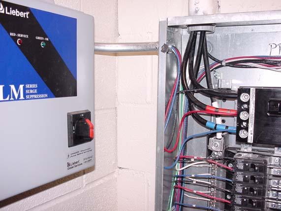

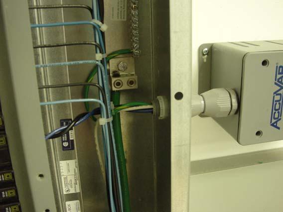
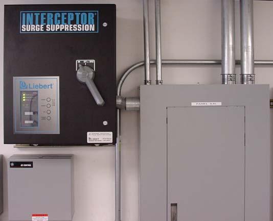
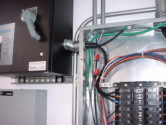
23 Example Installations Installation, Operation Liebert TVSS Units
24 Installation, Operation Liebert TVSS Units
25 Installation, Operation Liebert TVSS Units
26 Installation, Operation Liebert TVSS Units
27 Installation, Operation Liebert TVSS Units
28 POWER PROTECTION Liebert Corporation 1050 Dearborn Drive PO Box Columbus, OH Phone Fax US & Canada Web Site: SL Rev. 0 7/
DANGER DANGER: is used in this manual to warn of high voltages capable of causing shock, burns, or death.
 Installation/Operation Manual TABLE OF CONTENTS Page UNPACKING AND INSTALLATION Unpacking and Preliminary Inspection...2, 3 Model Number...9 LOCATION CONSIDERATIONS Environment, Equipment Performance,
Surge Protective Devices. STV100K Series. Instruction Manual
 Surge Protective Devices STV100K Series Instruction Manual Contents 1.0 Installation... 4 1.1 Environment... 4 1.2 Mounting... 4 1.3 Proper Connection of SPDs... 4 1.4 Mechanical Dimensions... 5 1.5 Voltage
HUBBELL SPIKESHIELD Wired-In Branch Panels Surge Protective Device (SPD)
") HUBBELL SPIKESHIELD Wired-In Branch Panels Surge Protective Device (SPD) Instruction Bulletin 8222-0513B Retain for future use. SPIKESHIELD Wired-In Branch Panels 8222-0513B 05/2012 Table of Contents Precautions...
HUBBELL SPIKESHIELD Wired-In Branch Panels Surge Protective Device (SPD) Instruction Bulletin 8222-0513B Retain for future use. SPIKESHIELD Wired-In Branch Panels 8222-0513B 05/2012 Table of Contents Precautions...
Surge Protective Devices. STV100K Series. Instruction Manual
 Surge Protective Devices STV100K Series Instruction Manual Contents 1.0 Installation... 4 1.1 Environment... 4 1.2 Mounting... 4 1.3 Proper Connection of SPDs... 4 1.4 Mechanical Dimensions... 5 1.5 Voltage
R-LB R-LX Series Installation, Operation & Maintenance Manual
 Installation, Operation & Maintenance Manual WARNINGS Safety First Hazardous Voltage & Shock Hazard Only qualified licensed electricians should install or service SPDs Hazardous voltages exist within SPDs
Installation and Operation Manual
 Installation and Operation Manual APC 2X Series Hardwire Products PMP2X-A PMF2X-A PMG2X-A PMH2X-A APC hardwired products are designed to provide specification-grade performance at the service entrance,
Liebert INSTALLATION, OPERATION AND MAINTENANCE MANUAL. Interceptor and Interceptor Hybrid Advantage Series Transient Voltage Surge Suppressors
 TRANSIENT VOLTAGE SURGE SUPPRESSION INSTALLATION, OPERATION AND MAINTENANCE MANUAL Interceptor and Interceptor Hybrid Advantage Series Transient Voltage Suppressors Liebert TRANSIENT VOLTAGE SURGE SUPPRESSION
Hubbell Surge Protective DeviceS
 Hubbell Surge Protective DeviceS Hubbell Modular Panel Products Surge Protective Devices (SPD) The Hubbell Modular Panel Product Surge Protective Devices (SPD) are designed to provide protection at the
Liebert AccuVar (ACV Series) Surge Protective Device (SPD) (With Noise Filtering) GUIDE SPECIFICATIONS for a Parallel Surge Suppression System
 Surge Protective Device (SPD) (With Noise Filtering) GUIDE SPECIFICATIONS for a Parallel Surge Suppression System") Liebert AccuVar (ACV Series) Surge Protective Device (SPD) (With Noise Filtering) GUIDE SPECIFICATIONS for a Parallel Surge Suppression System Part 1 General 1.01 Summary A. These specifications describe
Liebert AccuVar (ACV Series) Surge Protective Device (SPD) (With Noise Filtering) GUIDE SPECIFICATIONS for a Parallel Surge Suppression System Part 1 General 1.01 Summary A. These specifications describe
Liebert TVSS: The First Line of Defense - Product Overview. Jim Tiesi
 Liebert TVSS: The First Line of Defense - Product Overview Jim Tiesi INTERCEPTOR SURGE SUPPRESSION Overall Design True modular design Low impedance copper conduction plates Best in class performance Real-time
SECTION SURGE PROTECTION DEVICES. A. Section includes Surge Protection Devices for low-voltage power, control, and communication equipment.
 SECTION 26 43 00 SURGE PROTECTION DEVICES PART 1 - GENERAL 1.1 SUMMARY A. Section includes Surge Protection Devices for low-voltage power, control, and communication equipment. 1.2 DEFINITIONS A. ATS:
GE Digital Energy. Power Quality
 GE Digital Energy Power Quality INSTALLATION, OPERATION AND MAINTENANCE MANUAL GE TRANQUELL Enhanced Thermal Protection (ETP) Series Wall Mounted Medium and High Exposure Surge Protective Devices (SPDs)
Surge Protective Devices. Installation & Operation Manual. NEMA 12 (Steel) NEMA 1 (Non-Metallic) Model 350
 NEMA 1 (Non-Metallic) Model 350") Surge Protective Devices Installation & Operation Manual NEMA 12 (Steel) NEMA 1 (Non-Metallic) Model 50 ASCO SURGE PROTECTIVE DEVICE INSTALLATION, OPERATION AND MAINTENANCE MANUAL TABLE OF CONTENTS INSTALLATION
Surge Protective Devices Installation & Operation Manual NEMA 12 (Steel) NEMA 1 (Non-Metallic) Model 50 ASCO SURGE PROTECTIVE DEVICE INSTALLATION, OPERATION AND MAINTENANCE MANUAL TABLE OF CONTENTS INSTALLATION
Installation and Operation Manual
 Installation and Operation Manual APC Panel Mount Modular SPDs PMP3S-A PMP3DS-A PMP4S-A PMP4DS-A PMF3S-A PMF3DS-A PMF4S-A PMF4DS-A PMG3S-A PMG3DS-A PMG4S-A PMG4DS-A PML3S-A PML3DS-A PML4S-A PML4DS-A The
Specifications, Installation, and Operating Instructions
 Specifications, Installation, and Operating Instructions Model: Power Vantage AC Panel Protector CAUTION: The installation of a surge protection device () must be done by qualified electrical personnel.
SECTION TRANSIENT VOLTAGE SUPPRESSION FOR LOW-VOLTAGE ELECTRICAL POWER CIRCUITS
 SECTION 264313 - TRANSIENT VOLTAGE SUPPRESSION FOR LOW-VOLTAGE ELECTRICAL POWER CIRCUITS PART 1 - GENERAL 1.1 RELATED DOCUMENTS A. Drawings and general provisions of the Contract, including General and
INSTALLATION INSTRUCTIONS STZ-R SERIES (ENGLISH)
") Surge-Trap STZ-R series Surge Protective Device (SPD) Danger Hazard of Electrical Shock, Explosion or Arc Flash Only qualified licensed electricians should install or service SPDs Verify that all power
Surge-Trap STZ-R series Surge Protective Device (SPD) Danger Hazard of Electrical Shock, Explosion or Arc Flash Only qualified licensed electricians should install or service SPDs Verify that all power
300 Series 330/320 Surge Protective Device Installation, Operation and Maintenance Manual
 Power Switching & Controls For Business-Critical Continuity 300 Series 330/320 Surge Protective Device Installation, Operation and Maintenance Manual Installation, Operation and Maintenance Manual EMERSON
400 Series 460 Surge Protective Device Installation, Operation and Maintenance Manual
 400 Series 460 Surge Protective Device Installation, Operation and Maintenance Manual Installation, Operation and Maintenance Manual IO-70104 Rev 1, 1/2014 EMERSON NETWORK POWER SURGE PROTECTIVE DEVICE
INSTALLATION, OPERATION AND MAINTENANCE MANUAL GE TRANQUELL Series Wall Mounted Low and Medium Exposure Surge Protective Devices (SPDs)
") ga GE Digital Energy Power Quality INSTALLATION, OPERATION AND MAINTENANCE MANUAL GE TRANQUELL Series Wall Mounted Low and Medium Exposure Surge Protective Devices (SPDs) 2020005003 (12/09) Page 1 of 18
ga GE Digital Energy Power Quality INSTALLATION, OPERATION AND MAINTENANCE MANUAL GE TRANQUELL Series Wall Mounted Low and Medium Exposure Surge Protective Devices (SPDs) 2020005003 (12/09) Page 1 of 18
GENERAL UL th EDITION BID SPEC: SURGE PROTECTIVE DEVICES Prepared by THOR SYSTEMS, INC.
 [Refer to Engineering Notes at End of Spec] Section [16XXX] [264XXX] - SURGE PROTECTIVE DEVICES (SPDs) PART 1 - GENERAL 1.1 SCOPE A. This section includes Surge Protective Devices (SPDs) for low-voltage
Always "On" UPS Systems Inc. USER MANUAL
 Always "On" UPS Systems Inc. SMART HOME PROTECTOR USER MANUAL Bldg 1-150 Campion Road, Kelowna, BC, Canada, V1X 7S8 Phone: (250) 491-9777 Ext. 451, Fax: (250) 491-9775, Email: sales@alwaysonups.com Web
Instruction Manual: IM E
 Innovative Technology TVSS Products The I.T. Equalizer Installation Instruction Manual: IM01005011E Rev. 2 May 2009 Contents Page 1 Introduction... 1 1.1 Scope... 1 1.2 I.T. Equalizer Catalog Numbering
Total Protection Solutions Surge Protective Devices SurgeTrack Series: 080, 120, 160, 240, 300 and 400
 Total Protection Solutions SurgeTrack Series: 080, 120, 160, 240, 300 and 400 Surge Protective Devices Installation, Operation and Maintenance Manual SURGETRACK INSTALLATION, OPERATION AND MAINTENANCE
Surge Protective Devices Installation, Operation and Maintenance Manual. LoadTrack LTL
 LoadTrack LTL Surge Protective Devices Installation, Operation and Maintenance Manual P.O. Box 3760 Winter Park, FL 32790 USA TEL: 800-647-1911 www.tpssurge.com LOADTRACK LTL INSTALLATION, OPERATION AND
GENERAL UL th EDITION DESIGN-BUILD SPEC: SURGE PROTECTIVE DEVICES Prepared by THOR SYSTEMS, INC.
 [Refer to Engineering Notes at End of Spec] Section [16XXX] [264XXX] - SURGE PROTECTIVE DEVICES (SPDs) PART 1 - GENERAL 1.1 SCOPE A. This section includes Surge Protective Devices (SPDs) for low-voltage
1. Section Lightning Protection for lightning protection system. D. The installation shall be in conformance with NEC Article 285.
 SECTION 26 04 75 - SURGE PROTECTION DEVICES PART 1 - GENERAL 1.1 SUMMARY A. Applicable provisions of the General Conditions, Supplementary General Conditions and Special Conditions shall govern work performed
DIVISION 16 SECTION Surge Protective Device Submittal (SPD)
") DIVISION 16 SECTION 16289 Surge Protective Device Submittal (SPD) PART 1 -GENERAL 1.1 RELATED DOCUMENTS A. General: Drawings and general provisions of the Contract, including General and Supplementary
DIVISION 16 SECTION 16289 Surge Protective Device Submittal (SPD) PART 1 -GENERAL 1.1 RELATED DOCUMENTS A. General: Drawings and general provisions of the Contract, including General and Supplementary
SECTION SURGE PROTECTIVE DEVICES
 SECTION 16289 PART 1 GENERAL 1.01 RELATED DOCUMENTS A. Drawings and general provisions of the Contract, including General and Supplementary Conditions and Division 1 Specification Sections, apply to this
Series Amp Pad Mount Quick Connect Input and Output Power Panels
 Series 300 2000-4000 Amp Pad Mount Quick Connect Input and Output Power Panels DANGER is used in this manual to warn of a hazard situation which, if not avoided, will result in death or serious injury.
Surge Protective Devices Installation, Operation and Maintenance Manual. ServiceTrack ST Series: 080, 120, 160, 200, 240, 300 and 400
 ServiceTrack ST Series: 080, 120, 160, 200, 240, 300 and 400 Surge Protective Devices Installation, Operation and Maintenance Manual TEL: 800-853-8265 www.innosyspower.com SERVICETRACK ST INSTALLATION,
Instruction Bulletin Boletín de instrucciones Directives d'utilisation , Rev. 02, 03/2016
 Surgelogic EMA Series Surge Protective Devices (SPDs) Dispositivos de protección contra sobretensiones transitorias (SPD) Dispositifs de protection contre les surtensions transitoires (SPD) Instruction
Installation Notes TII Model 341 Protector
 Installation Notes TII Model 341 Protector (ATT-IS PEC 32918) for MERLIN Communications System In Range Out of Building (IROB) Station Installation By Trained Technician Only WARNING: Failure to follow
SURGE PROTECTION USER MANUAL. Surge Protection Device PORTABLE POWER DISTRIBUTION SURGE PROTECTION DEVICE (SPD) B
 B") SURGE PROTECTION PORTABLE POWER DISTRIBUTION SURGE PROTECTION DEVICE (SPD) USER MANUAL Surge Protection Device B 01 156 9000 This Surge Protection Device is intended for professional use only Read this
SURGE PROTECTION PORTABLE POWER DISTRIBUTION SURGE PROTECTION DEVICE (SPD) USER MANUAL Surge Protection Device B 01 156 9000 This Surge Protection Device is intended for professional use only Read this
Instruction Manual IM E Table of Contents
 Instruction Manual IM01005031E Effective For Mounting External To Table of Contents 1.0 Introduction 2.0 Installation 3.0 Operating Features 4.0 Troubleshooting 5.0 Specifications 6.0 Ordering Guidelines
Specifications 1 Installation Procedures 2 Wiring Diagrams 3 Installation Checklist 5 Maintenance 5 Warranty Information 6 Material Return Policy 6
 CFS Family TITLE PAGE Specifications 1 Installation Procedures 2 Wiring Diagrams 3 Installation Checklist 5 Maintenance 5 Warranty Information 6 Material Return Policy 6 Part Number Model Description A70-00-5006
Surge Protective Devices. Installation & Operation Manual. Model 570/575. Model 575 Model 570 Model 565 Model 560. Model 560/565
 Surge Protective Devices Installation & Operation Manual Model 570/575 Model 560/565 Model 575 Model 570 Model 565 Model 560 Installation, Operation and Maintenance Manual 2 ASCO SURGE PROTECTIVE DEVICE
Series Amp Quick Connect Input and Output Power Panels
 Series 300 1200-1600 Amp Quick Connect Input and Output Power Panels DANGER is used in this manual to warn of a hazard situation which, if not avoided, will result in death or serious injury. WARNING is
Application Techniques CENTERLINE 2100 Motor Control Centers
 POWER SYSTEM CONSIDERATIONS FOR PRODUCT SELECTION Application Techniques CENTERLINE 2100 Motor Control Centers Power System Considerations for Product Selection i Power System Considerations for Product
BSPD Surge Protective Devices
 BUSSMANN Supersedes December 2016 SERIES BSPD Surge Protective Devices High capacity Type 1 and Type 2 SPDs for overvoltage protection on Contents Description Page Introduction 2 Applications 2 Features
Installation Instructions & User Manual
 Installation Instructions & User Manual ZONEMASTER PRO AC Panel Transient Voltage Surge Suppressors The Wiremold Company In US: 60 Woodlawn Street, West Hartford, CT 06110 800-621-0049 FAX 860-232-2062
Eaton s Innovative Technology Surge Suppression Guideform Specification High Exposure DIVISION 16 SECTION 16289
 PART 1 - GENERAL DIVISION 16 SECTION 16289 TRANSIENT VOLTAGE SURGE SUPPRESSION (TVSS) 1 RELATED DOCUMENTS General: Drawings and general provisions of the Contract, including General and Supplementary Conditions
Eaton s Innovative Technology Surge Suppression Guideform Specification Low Exposure DIVISION 16 SECTION 16289
 PART 1 - GENERAL DIVISION 16 SECTION 16289 TRANSIENT VOLTAGE SURGE SUPPRESSION (TVSS) 1.1 RELATED DOCUMENTS General: Drawings and general provisions of the Contract, including General and Supplementary
Surge Protective Devices. STV25K Series. Instruction Manual
 Surge Protective Devices STV25K Series Instruction Manual Contents 1.0 Installation & Operation... 4 1.1 Environment... 4 1.2 Mechanical Dimensions... 4 1.3 DIN Rail Mounting... 5 1.4 Supplemental Enclosures...
Installation, Operation, and Service Manual SIEMENS HEALTHCARE INTEGRATED ELECTRICAL CABINET
 Technical Publications SIEMENS HEALTHCARE INTEGRATED ELECTRICAL CABINET for ARTIS Q / Q.ZEN / ONE ARTIS ZEEGO / ZEEGO.ZEN ARTIS ZEE MULTIPURPOSE SINGLE PLANE IECAX480V125A Main Disconnect Panel Bevco Engineering
User s Manual. ACS550-PD Stock 3R Irrigation Packaged Drive Supplement to ACS550-U1 User s Manual
 User s Manual ACS550-PD Stock 3R Irrigation Packaged Drive Supplement to ACS550-U1 User s Manual 2 ACS550-PD 3R Irrigation Packaged Drive ACS550 Drive Manuals GENERAL MANUALS ACS550-U1 User s Manual (1
Eaton s SPD Series for integration into electrical distribution equipment
 Technical Data TD01006E Supersedes August 2009 Eaton s SPD Series for integration into electrical distribution equipment Contents Description Page Introduction....2 Applications....2 Features....2 Standards
PDI Modular Compact Remote Power Panel
 Guide Specifications (Revision 000, 6/17/2016) 1 GENERAL 1.1 Summary These specifications describe requirements for a remote power panel (RPP) distributing power to sensitive loads. These specifications
Eaton Innovative TechnologyT XT50/100 surge protective device
 Instruction Manual IM01005014E Supersedes January 2014 Eaton T /100 surge protective device Contents Description Page Introduction.... 2 Installation.... 2 Specifications... 7 Operation..... 7 Warranty...
Installation Manual. APEX Series. Silicon and MOV Panel Protection. APEX Series
 Installation Manual APEX Series Silicon and MOV Panel Protection APEX Series APEX Series Installation Guide 2 Table of Contents Mechanical Installation 3 Table One - Application Rating 3 Figure 1 - Mounting
Models 120LS, 200LS, 300LS, 400LS, 560LS Installation Instructions
 299-600-96 Rev. F MCG Surge Protection Models 120LS, 200LS, 300LS, 400LS, 560LS Installation Instructions Important Warranty Information: MCG surge protectors are designed to work at specific voltages
SECTION DISTRIBUTION SWITCHBOARDS
 PART 1 - GENERAL 1.1 DESCRIPTION: SECTION 26 24 11 This section specifies the furnishing, installation, and connection of the distribution switchboards. 1.2 RELATED WORK: A. Section 13 05 41, SEISMIC RESTRAINT
Quick Start Guide TS A
 Quick Start Guide TS 930 125-630A DANGER HAZARD OF ELECTRICAL SHOCK, EXPLOSION, OR ARC FLASH Read and understand this quick start guide before installing and operating the transfer switch The installer
B. System Design and Performance Requirements
 Change History Date Description of Change Pages / Sections Modified 6/15/16 Updated division section from 16289 to 26 35 00, removed references to other section numbers 10/14/14 Amend text in section B
2.1. SPD, Power Conditioning, PF Capacitors and Harmonic Filters. Contents Description. Introduction. Surge Protection and Power Conditioning
 .1 Industrial and Commercial Surge Protection Introduction Industrial and Commercial Surge Protection SPD Series for Integration into Electrical Distribution Equipment SPD Series for Mounting External
Total Home Surge Protection for Point-of-Entry. FirstSurge TM. User Manual - Canada (English)
") Total Home Surge Protection for Point-of-Entry FirstSurge TM User Manual - Canada (English) www.siemens.ca/surge Introduction Thank you for choosing the Siemens FirstSurge Residential Surge Protective
Total Home Surge Protection for Point-of-Entry FirstSurge TM User Manual - Canada (English) www.siemens.ca/surge Introduction Thank you for choosing the Siemens FirstSurge Residential Surge Protective
Installation Instructions for Eaton Surge Protective Device XXCFXXX10-DIN and XXCFXXX10-DIN2
 Supersedes 6/2015 Surge Protective Device XXCFXXX10-DIN and XXCFXXX10-DIN2 XXCFXXX10-DIN Contents Description Page 1.0 Setup...2 1.1 Before Installation...2 1.2 Installation...3 For AC Applications...3
TPS3 09. Surge Protective Device. User Manual - USA
 TPS3 09 Surge Protective Device User Manual - USA V WARNING - Hazardous Voltage & Shock Hazard Failure to Follow These Instructions Could Result in Death or Serious Injury Only qualified licensed electricians
MICHIGAN DEPARTMENT OF TRANSPORTATION
 MICHIGAN DEPARTMENT OF TRANSPORTATION SPECIAL PROVISION FOR GROUNDING, BONDING, LIGHTNING PROTECTION AND SURGE PROTECTION FOR INTELLIGENT TRANSPORTATION SYSTEM EQUIPMENT ITS:CLC 1 of 5 APPR:LWB:DBP:07-31-13
User s Manual. ACS550-PD 3R Irrigation Packaged Drive Supplement to ACS550-U1 User s Manual
 User s Manual ACS550-PD 3R Irrigation Packaged Drive Supplement to ACS550-U1 User s Manual 2 ACS550-PD 3R Irrigation Packaged Drive ACS550 Drive Manuals GENERAL MANUALS ACS550-U1 User s Manual (1 200 HP)
PowerLogic High Density Metering System 1-Meter Enclosure
 PowerLogic High Density Metering System 1-Meter Enclosure Installation Guide 63230-508-211A1 Safety information PowerLogic High Density Metering System 1-Meter Enclosure Important information Read these
TransGuard. Electrical Transient Suppression Filter Systems. Installation, Operation and Maintenance Manual PN ,
 Installation, Operation and Maintenance Manual PN 750-0068-003, TransGuard TransGuard Electrical Transient Suppression Filter Systems A member of the MasterPlan family of products 2002, Danaher Power Solutions
Installation, Testing, and Operating Procedures 30 AMP PORTABLE AND PERMANENT SERIES GFCI SINGLE and MULTIPHASE
 IMPORTANT! Please read all the information on this sheet. SAVE THESE INSTRUCTIONS! NOTICE BEFORE USING READ INSTRUCTIONS COMPLETELY. TO BE INSTALLED BY A QUALIFIED ELECTRICIAN IN ACCORDANCE WITH NATIONAL
ZoneMaster Series Surge Protection Devices
 ZoneMaster Series Surge Protection Devices New Improved ZoneMaster Series Configurable Hard-Wired Surge Protection Devices Wiremold ZoneMaster Series Surge Protection Devices are fully configurable panel
THE SURGE PROTECTION SOLUTION
 THE SOLUTION Unique product features and benefits never before offered in the surge protection industry POWER QUALITY INTERNATIONAL, LLC 2404 Merchant Ave., Odessa, Florida, USA 33556 (888) 539-7712 PowerQuality.net
SECTION TRANSIENT VOLTAGE SURGE SUPPRESSION
 SECTION 16709 TRANSIENT VOLTAGE SURGE SUPPRESSION PART 1 GENERAL 1.01 SUMMARY A. Section Includes: Transient Voltage Surge Suppression (TVSS) devices, also known as Surge Protective Devices (SPDs), for
Installation Instructions
 50ES, 50EZ, 50GL, 50GS, 50GX, 50JS, 50JX, 50JZ, 50SD, 50SZ, 50VL, 50VT, 50XP, 50XZ 601A, 602A, 602B, 604A, 604B, 604D, 607C, 701A, 702A, 702B, 704A, 704B, 704D, 707C PA1P, PA2P, PA3P, PH1P, PH2P, PH3P
high RESISTANCE STOPLIGHT Instruction Manual C-101EM
 stoplight high RESISTANCE GROUNDING SYSTEM STOPLIGHT Instruction Manual C-101EM high resistance grounding protection The StopLight system uses a unique indicator light system to provide visual detection
SECTION PANELBOARDS
 SECTION 16450 PART 1 - GENERAL 1.01 DESCRIPTION A. Section includes requirements for panelboards providing fault interrupting capability and overcurrent protective devices. 1.02 REFERENCE STANDARDS A.
APPLICATION CONTROL GUIDELINES. IntelliROL Power Supply PN Revision Date: March 15, 2017
 APPLICATION CONTROL GUIDELINES IntelliROL Power Supply PN 1176718 Revision Date: March 15, 2017 Table of Contents List of Tables...3 TGW Safety Recommendation...4 Warnings and Safety Instructions...5 Introduction...6
Surgelogic Surge Protective Device I-Line Plug-On Unit Series
 Surgelogic Surge Protective Device I-Line Plug-On Unit Series Catalog 1310CT0201R5/07 2007 Class 1310 CONTENTS Description Page Product Description.................................................. 2 Application
Symmetra PX 160. Maintenance Bypass Enclosure. Installation 05/
 Symmetra PX 160 Maintenance Bypass Enclosure Installation 05/2014 www.schneider-electric.com Legal Information The Schneider Electric brand and any registered trademarks of Schneider Electric Industries
SECTION 16450: NON-AUTOMATIC TRANSFER SWITCH / QUICK CONNECT GENERATOR SWITCHBOARD <S> <OM>
 SECTION 16450: NON-AUTOMATIC TRANSFER SWITCH / QUICK CONNECT GENERATOR SWITCHBOARD PART 1 - GENERAL 1.1 RELATED DOCUMENTS A. Drawings and general provisions of the Contract, including General
Explosion-Protected Arc-Fault Protection ExAFCI Arc-Fault Circuit Interrupter
 Installation, Operation & Maintenance Sheet Explosion-Protected Arc-Fault Protection ExAFCI Arc-Fault Circuit Interrupter > Contents 1 Contents 1 Contents...2 2 General Information...2 2.1 Manufacturer...2
SOUTH CAROLINA ELECTRIC COOPERATIVES SECONDARY TYPE 1 SURGE PROTECTIVE DEVICE SPECIFICATIONS Updated/Revised: October 6, 2014
 SOUTH CAROLINA ELECTRIC COOPERATIVES SECONDARY TYPE 1 SURGE PROTECTIVE DEVICE SPECIFICATIONS Updated/Revised: October 6, 2014 1.0 SCOPE This secondary Type 1 surge protective device specification covers
SPECIAL SPECIFICATION 1864 Pole Mounted Cabinet
 1993 Specifications CSJ s 0924-06-221,etc. & 0924-06-223 SPECIAL SPECIFICATION 1864 Pole Mounted Cabinet 1. Description. This specification describes the minimum acceptable requirements for a weatherproof
SIEMENS HEALTHCARE INTEGRATED ELECTRICAL CABINET
 Product Data Sheet Technical Publications SIEMENS HEALTHCARE INTEGRATED ELECTRICAL CABINET for ARTIS Q / Q.ZEN / ZEE BIPLANE IECAX480V225A Main Disconnect Panel Bevco Engineering Company, Inc. CONFIDENTIAL
TPS3 Internal Manual. Surge Protective Device. User Manual - Canada
 TPS3 Internal Manual Surge Protective Device User Manual - Canada V WARNING - Hazardous Voltage & Shock Hazard Failure to Follow These Instructions Could Result in Death or Serious Injury Only qualified
SECTION SWITCHBOARDS
 SECTION 26 24 13 PART 1 - GENERAL 1.1 SUMMARY A. Work Included: 1. Switchboards 2. Commercial Metering Switchboards 3. Non-Utility Power Meters (Microprocessor-Based Metering Equipment) PART 2 - PRODUCTS
SAVE THESE INSTRUCTIONS
 OUTDOOR HARDWIRE INSTALLATION INSTRUCTIONS Please read and save these instructions. Read carefully before using product. Protect yourself and others by observing all safety information, warnings and cautions.
Surge Protective Devices. Installation & Operation Manual. Model 457
 Surge Protective Devices Installation & Operation Manual Model 457 WARNING IMPORTANT PLEASE READ WARNING Safety First Hazardous Voltage & Shock Hazard Only qualified licensed electricians should install
Wise HP33 THREE PHASE HIGH PRECISION AVR SURVO-MOTOR AUTOMATIC VOLTAGE STABILIZER
 Wise HP33 THREE PHASE HIGH PRECISION AVR SURVO-MOTOR AUTOMATIC VOLTAGE STABILIZER LEN.MAN.STA.111 Rev.4.00/2010 CONTENTS 1. SAFETY INSTRUCTIONS 1 2. INTRODUCTION 2 3. FRONT PANEL AND CONNECTION BOARD 3
Maximum Reliability & Excellent Value. Features. UL Listed Withstand & Close-On Ratings. Series 300 Power Transfer Switches
 Series 300 Power Transfer Switches Maximum Reliability & Excellent Value With a Series 300 Transfer Switch, you get a product backed by ASCO Power Technologies, the industry leader responsible for virtually
Model HU-224/225. Technical Information TI.224/ Humidity Transduce r FOR ADDITIONAL INFORMATION SEE HU-224/225 DATA SHEET
 Model /225 FOR ADDITIONAL INFORMATION SEE /225 DATA SHEET SPECIFICATIONS Accuracy*: ± 2% / ± 3% RH Range: 0-100% RH Hysteresis: ± 1% Supply Voltage:12-40 VDC 12-35 VAC (VDC output units only) Supply Current:
Quick Start Guide TS 870 ATS
 Quick Start Guide TS 870 ATS 100A - 800A (with TSC 900 Controller) DANGER HAZARD OF ELECTRICAL SHOCK, EXPLOSION, OR ARC FLASH Read and understand this quick start guide before installing and operating
Obtaining Documentation and Submitting a Service Request, page xvii Safety Warnings, page xvii Safety Guidelines, page xx
 Preface Obtaining Documentation and Submitting a Service Request, page xvii Safety s, page xvii Safety Guidelines, page xx Obtaining Documentation and Submitting a Service Request For information on obtaining
Sync Control. Installation/Operation Manual Rev. E
 9 315 Sync Control Installation/Operation Manual 164201140 Rev. E ------------------------------------------------------------------------ ------------------------------------------------------------------------
UPS READY POWER DISTRIBUTION ASSEMBLY
 UPS READY POWER DISTRIBUTION ASSEMBLY FOR TRAFFIC CABINETS with LED Signals INSTALLATION & OPERATOR S MANUAL VERSION 1.2 1 Note The instructions contained in this manual are not intended to cover all of
Internal Modular SPDs
 Internal Modular SPDs Square D Internally Mounted Protective Devices Square D TM brand logic TM internal modular Protective Devices (SPDs) deliver specification grade performance for service entrance or
S66 Series Electronic Fan Speed Control
 FANs 121, 125, 1628.3 Product/Technical Bulletin S66 Issue Date 0918 S66 Series Electronic Fan Speed Control The S66 Series Electronic Fan Speed Control is designed to modulate the speed of single-phase,
Surge Protection Devices (SPD)
") TPS3 03 TPS3 03 is a UL 1449 3rd Edition, cul 50 ka Type 1 (Type cul) compact Surge Protective Device. For cul applications, the TPS3 03 can be used as a secondary surge or lighting arrestor alternative
TPS3 03 TPS3 03 is a UL 1449 3rd Edition, cul 50 ka Type 1 (Type cul) compact Surge Protective Device. For cul applications, the TPS3 03 can be used as a secondary surge or lighting arrestor alternative
File E Project 08NK November 24,2009 REPORT TRANSIENT VOLTAGE SURGE SUPPRESSORS (VZCA/VZCA7)
") File E3456 Project 08NK10151 November 24,09 REPORT ON TRANSIENT VOLTAGE SURGE SUPPRESSORS (VZCA/VZCA7) *********************************************************** Complementary Product Category ELECTROMAGNETIC
File E3456 Project 08NK10151 November 24,09 REPORT ON TRANSIENT VOLTAGE SURGE SUPPRESSORS (VZCA/VZCA7) *********************************************************** Complementary Product Category ELECTROMAGNETIC
Measure Ø-N, Ø-Ø, Ø-Gnd with voltmeter to confirm application voltage prior to installation.
 Product No. 99-600-91 Rev. B Page 1 of 8 MCG Surge Protection Model 160MXT Installation Instructions Important Warranty Information MCG surge protectors are designed to work at specific voltages and configurations,
920 Remote Control (RC) Switches
 Switches") 920 Remote Control (RC) Switches ASCO is the global leader in power switching and controls ASCO 920 PRODUCT SPECIFICATIONS SWITCH ONLY (PANELBOARD MOUNTING) 1,2,3 () DIMENSIONS, IN.(MM) WIDTH HEIGHT DEPTH
920 Remote Control (RC) Switches ASCO is the global leader in power switching and controls ASCO 920 PRODUCT SPECIFICATIONS SWITCH ONLY (PANELBOARD MOUNTING) 1,2,3 () DIMENSIONS, IN.(MM) WIDTH HEIGHT DEPTH
Outdoor Risk and Equipment Protection
 Outdoor Risk and Equipment Protection The proper use of surge suppressors, lightening arrestors, and weatherproof enclosures are critical protection measures for all outdoor wireless and IP video devices.
TransEnd Surge Suppression Filter Systems
 Installation, Operation and Maintenance Manual P 750-0064-REV. 44 TransEnd TransEnd Surge Suppression Filter Systems TransEnd 100 TransEnd 80 TransEnd 50 TransEnd 25 JOSLY ISTALLATIO, OPERATIO AD MAITEACE
Installation Instructions & User Manual POWERWARE TVSS ZONESENTINEL. AC Panel Transient Voltage Surge Suppressors
 Installation Instructions & User Manual POWERWARE TVSS ZONESENTINEL AC Panel Transient Voltage Surge Suppressors INTRODUCTION This document explains how to install the Powerware TVSS ZoneSentinel AC Panel
for the SPV Installation and Operation Manual Instruction Manual IM E Contents
 Rev. 3 Contents Description Page 1. Introduction............................ 2 2. Preparation............................ 2 3. Installation Procedures................... 3 4. Ordering Guidelines......................
Solar Combiner Enclosure
 Installation Instructions Solar Combiner Enclosure Catalog Numbers 1000-SB006, 1000-SB012 Topic Page Description 1 Important Safety Instructions 3 Nameplate Data 4 Planning for Installation 4 Install the
SAVE THESE INSTRUCTIONS
 READ AND FOLLOW ALL SAFETY INSTRUCTIONS! SAVE THESE INSTRUCTIONS AND DELIVER TO OWNER AFTER INSTALLATION IMPORTANT SAFEGUARDS! When using electrical equipment, basic safety precautions should always be