百年品质, 值得信赖 您的产品名称. MACH3 Ethernet Card NVEM. Manual
|
|
|
- Virgil Porter
- 6 years ago
- Views:
Transcription


1 百年品质, 值得信赖 您的产品名称 MACH3 Ethernet Card NVEM Manual


2 M 请在这里输入您的公司名称或产品名称 Contects Chapter 1. Introduction Product Introduction Products specification Products Appearance an struction and size substantival explanation Noting and Waring Chapter 2. Connection Device Power supply Solution Product connection define and method Chapter 3. Software Installation MACH3 Install MACH3 Registration NVEM Plug-in installation Chapter 4. Setting of software Open software Software Common settings Chapter 5. Using of software Set Machine Coordinate system Set workpiece coordinate system Open G code file and run Chapter 6. Question & Answer Q&A for Hardware Q&A for Software Chapter 7. Contract us
3 Chapter1 Introduction Chapter 1. Introduction 1.1 Product Introduction Novusun CNC has engaged in the Numerical control industry for 7 years,specialized in the research,development and production of various CNC controller systems with high quality and high reliability.we produce the Brushless DC motor,stepper motor driver,and also 1 to 6 aixs CNC motion controllers. NVEMv1.1 is the 3-6 axis motion controller we spend 4 years to design. NVEMv1.1 support Mach3 software and standard MPG,through Ethernet to communicate with computer,just use the Twine to connect directly or transfer with router. NVEMv1.1 motion controller adopts the ARM design framework.the ARM design includes communication,codeanalytic,underlying algorithm and pulse gerneration. Rational design,reliablecontrol,convenient operation. This manual introduces operation,connection and usage schedule of our professional motion controller for engraving machine.through a lot of the drawing the users can learn quickly how to use this motion controller. 1.2 Products specification Support Ethernet; 12 ports photoelectric isolated input interface for ordinary digital data; 10 ports photoelectric isolated output interface for ordinary digital data; 1 port 0-10V spindle speed analog output interface(can change to PWM output); - 1 -


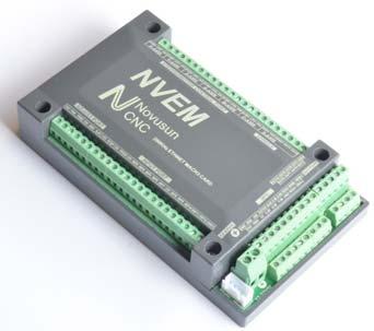
4 Chapter1 Introduction can support 3-6 axis stepper systems,200khz pulse output for every axis; ARM motion control chip; main device is 12V-32VDC power supply input,current should higher than 0.5A; Compatible with MPG input,support the digital display MPG from our company 1.3 Products Appearance and size NVEMv1.1 motion controller is with the sealed shell structure,there are 4pcs setting holes at the bottom.we can fix 4pcs 4mm diameter holes at the cabinet,and install the controller into the cabinet.the controller appearance as the Figure 1-1 and Figure 1-2 show: The products overall size is 163.1mm*80.8mm*27.8mm; The bottom install size is 101.4mm*39.5mm Figure1-1. NVEMV1.1 front appearance and size - 2 -

5 Chapter1 Introduction Figure1-2. The other side of NVEMV1.1and installation dimensions 1.4 substantival explanation When operate the NVEM,where will be a lot of English abbreviation,now we list all of them for your kindly references: FRO:Feedingadjust:During the operating process,the F value already set,and need to adjust the current feeding speed, then we can adjust FRO value to realize it. SRO: Spindle speed adjust: During the operating process, the S value already set, and need to adjust the current spindle speed, then we can adjust SRO value to realize it : - 3 -
6 Chapter1 Introduction Current Speed S#=setting S*SRO. SRJ:speed adjust manually During the operating process,as the manual speed already set,and we need to adjust the current speed,and impossible to fix the value during it is working,then we can revise the SRJ value to realize it. Current manual speed FS#=Setting manual speed*srj. F:Feedingspeed,the unit is mm/min.for example F=200,means every minute feeding 2000mm. S: Spindle Speed. Unit is rad/min.for example S=20000,means revolution/minute. X axis Coordinate Y axis Coordinate Z axis Coordinate A axis Coordinate B axis Coordinate C axis Coordinate Ready:ReadyMode.In the mode we can do any operation,include processing or values modification or starting 2nd mode. Reset: Reset mode.in this mode,it should stop every operation. Step :Manual Step Mode. Every axis candonduct the manual step operation at this mode. MPG: MPG mode.every axis can conduct the MPG operation at this mode


7 Chapter1 Introduction 1.5 Noting and Waring Free from exposure to the electronics without waterproof function.please environment as dry as possible. This is the icon. Wiring warning, the IO input terminal of this equipment support the equipment with source switch (such as Inductive proximity switch.)when using such kind of switch, attention please: avoid the +terminal and terminal of power supply to connect with GND.This equipment s analogy quantity output terminal of spindlecontrolalos have a certain load capacity. Please avoid this terminal connect with GND.in case that the interior components and parts be brokendown. Operation warning, Please do the security measures well when connecting with the machine tools.the ESTOP, limit and other things must be perfected.when comes across the emergancy, please press the ESTOP key at once or cut off the power directly, thus avoiding the equipment damage and casualty. High voltage danger, the primary device is 18-32VDC power supply.voltage equipment.pls pay attention to the electricity, safety when conducting the operation - 5 -

8 Chapter2 Connection Chapter 2. Connection 2.1 Device Power supply Solution The power supply solution in the field of the Industrial automation is always very complicated,there is a lot of the GND,now we descript the structure of the power supply as below: The power supply structure as the Figure 2-1,main power supply input and MPG module and stepper control output module are common GND,Limited and Estop input module and Spindle speed adjust M3/M8/M1 module are common GND,between main power supply and output module there are photoelectric isolation.the inputs of limited switch and Estop and so on are Common anode, inside of the device, there is +12VDC as common+,no need to connect external power supply. Based on the reference of output GND interface, output a 0-10V adjustable voltage to adjust the the spindle speed,m3/m8/m10 digital output interface is open-gnd. If connect an external relay,need to output GND to refer to,and give the relay an external power supply. Figure2-1. Power supply structure of NVEM - 6 -

9 Chapter2 Connection 2.2 Product connection define and method Figure2-2. Product wiring section and interface summary As the Figure 2-2 showed,the connection of the controller includes power supply interface,ethernet connection interface,mpginterface,stepper/servo control output interface,spindle control output interface, Estop and limited switch and tool setting input interface and so on. Now we descript them in details as below Stepper motor control interface As Figure 2-2 showed,no.1 terminal block is 6 axis stepper driver control output interface, from left to right,there are X,Y,Z,A,,B,C 6 axis output, it s common anode,the cable connection for each axis is COM+/CP-/DIR-, COM is common+,cp is Pulse-, DIR is direction-.connection showed as Figure 2-3.COM+ connect with the SP+ and DIR
10 Chapter2 Connection Pin mark Axis Definition COM+ Commom+ common anode +5V CPX- X axis Pulse output- for X axis DIX- X axis Directrion output- for X axis CPY- Y axis Pulse output- for Y axis DIY- Y axis Directrion output- for Y axis CPZ- Z axis Pulse output- for Z axis DIZ- Z axis Directrion output- for Z axis CPA- A axis Pulse output- for A axis DIA- A axis Directrion output- for A axis CPB- B axis Pulse output- for B axis DIB- B axis Directrion output- for B axis CPC- C axis Pulse output- for C axis DIC- C axis Directrion output- for C axis Table 2-1. Stepper driver control interface define - 8 -

11 Chapter2 Connection Figure2-3. Stepper driver connection Spindle control output We define the interface from left are: GND1(Output GND),VSO(0-10V adjustable speed output),index(spindle speed feedback input),out1(common output port 1),OUT2(common output port 2),. Take Nowforeuer inverter as the example. Spindle control output and the inverter connection showed as Figure 2-4.If ACM and DCM are closed,only need to connect one port. If need the Mach 3 to show the real in time spindle speed,just fix one hall device,every revolution send one pulse between INDEX and GND1,pulse voltage is 5V-10V


12 Chapter2 Connection Figure2-4. spindle control output and inverter connection VSO real output voltage=10v*s spindle setting speed/max spindle speed.forexample,if max spindle speed is 24000,current spindle speed is S=18000,so the VSO output voltage=10*18000/24000=7.5v. Max. spindle speed setting ports as showed sa Figure 2-5,open it from Pulley from Menu config.the current spindle speed can be set by S directive or Mach 3 spindle setting speed module. Figure2-5. Max spindle speed setting position
 and GND,to control the relay output,theconection as the Figure 2-6.")
13 Chapter2 Connection Common IO output interface Common IO output include OUT1,OUT2 on the spindle interface,totally 10 ports IO output,open drainoutput,internal structure as Figure 2-6: Figure2-6. OUT1-OUT10 internal structure Now just make a switch between OUTX(X=1-10) and GND,to control the relay output,theconection as the Figure 2-6.External power supply need to accord with the relay specification,the internal optocoupler GND open circuit only can absorb less than 50mA current,if relay absorb the current over 50mA,pls add current amplifier.in the Figure connect with OUT3,the others similar

14 Chapter2 Connection Figure2-7. OUTX connect with external relay method MPG connection The MPG port totally have 18 wiring terminals, and the reference of eachwiring terminal definition is table 2-2. The reference of corresponding relation between system and MPG wiring is table 2-3 and table 2-4. Pin mark Definition Notes GND MPG Ground MPG power supply GND. TXD MPG serial communication For the digital display MGP communication Output Port RXD MPG serial For the digital display MPG communication communicationinput Port 100X 100X multiplication short connect with GND means 100X switch multiplication,cutoff means no pulse 10X 10X multiplication short connect with GND means 10X switch multiplication,cutoff means no pulse
15 Chapter2 Connection 1X 1 X multiplication short connect with GND means 1X switch multiplication,cutoff means no pulse ESTOP MPG Estop short connect with GND means Estop effective,cutoff show invalid C-IN C Axis selected switch Short connect with GND meanas selecting C aixs,cutoff means don t select B-IN B Axis selected switch Short connect with GND meanas selecting B aixs,cutoff means don t select A-IN A Axis selected switch Short connect with GND meanas selecting A aixs,cutoff means don t select Z-IN Z Axis selected switch Short connect with GND meanas selecting Z aixs,cutoff means don t select Y-IN Y Axis selected switch Short connect with GND meanas selecting Y aixs,cutoff means don t select X-IN X Axis selected switch Short connect with GND meanas selecting X aixs,cutoff means don t select VDD5 MPG power supply 5V MPG power supply 5V output output WHA+ MPG A Phases Positive MPG A Phase differential Input Positive WHB+ MPG B Phases Positive MPG B Phase differential Input Positive WHA- MPG A Phases Negative MPG A Phase differential Input Negative WHB- MPG B Phases Negative MPG B Phase differential Input Negative Table 2-2. NVEM on MPG s define and explaination

16 Chapter2 Connection NVEM PIN No. Estop 1multiplication 1 10multiplication 10 MPG pin No. and color C X1 X10 100multiplication 100 X selecting Y selecting Z selecting X100 X Y Z A selecting 4 B selecting 5 C selecting 6 A Phase + A+ A Phase - A- B Phase + B+ B Phase - B- GND 0V/CN/COM +5V-W +5V Table 2-3. Connection between Differential MPG and NVEM Note: It you want to use the single-terminal MPG (namely there is no A-B-MPG), please look at the wiring table, the table 2-4 for reference. As for the unlisted one, please take the differential MPG wiring mode. NVEM Pin No. MPG Pin No. and color
17 Chapter2 Connection WHA+ A+ green WHA- 0V Black WHB+ B+ white WHB- 0V Black Table 2-4. Connection Between Single MPG and NVEM Main power supply input Interface As the Figure 2-2 show,no. 5 position interface is the main power supply input,marked + is the power supply positive,the other one wasn t marked is the negative,power supply voltage is 12-32VDC,Current must be not less then 1A Commnication external interface As the Figure 2-2 showed,the marked No. 6 position is communication external port,this port wasn t defined yet Estop limited Tool setting input interface.as the Figure 2-2 showed, Marked No. 7 position is the Estop limited ect. they are the optical isolatedinput interface,from the left,there are12v, STOP,12V,PROB,12V,INP3,INP4,INP5, INP6,INP7,12V,INP8,INP9,INP10,INP11,INP12,GND.Here STOP is INPUT1,and PROB is INPUT2. Internal structure Figure of Input interface see as Figure 2-8 ESTOP connect with NVEM see as Figure 2-9.Probe connect see as Figure

18 Chapter2 Connection Figure2-8. Internal structure drawing of Input interface Figure2-9. Estop input connection
19 Chapter2 Connection Figure2-10. Tool Setting Connection Drawing 2 lines Proximity Switch/ordinary frettingswitch drawing see as Figure 2-11 Figure lines Proximity Switch/ordinary frettingswitch drawing 3 lines Proximity Switch connection Figure 2-12,brown cable for Proximity switch connect with 12V,Black cable connect channel,blue cable connect with GND1. Only support PNP 3lines proximity switch

 to modify FRO,SROand SJR.")
20 Chapter2 Connection Figure2-12. PNP 3 lines Proximity Switch connection drawing Parameter adjust interface By this adjust interface,user can use a muti-position switch and adigital potentionmeter(simple encoder) to modify FRO,SROand SJR.Wiring method see as figure2-13 simple encoder's COM A B connect to 12V/FHA/FHB,and muti-position switch connect to 12V SRO SJR.If 12Vdon't connect to SRO or SJR,current effective parameter is FRO, if 12V connect to SRO,current effective parameter is SRO,and if 12V connect to SJR current effective parameter is SJR. Figure2-13. Parameter adjust interface


21 Chapter2 Connection Ethernet Port As the Figure 2-2 show,the marked No. 9 port is Ethernet communication port,nvemcommunicate with mach 3 through it.here we desgined 2 kinds communication mode,one is communication with network cable,one is communication with router,router is a better way to communicate,it won t occupy the LAN port on PC,PC can control the NVEM and also can have the internet. If we use the wireless router, then can control the NVEM by wireless. NVEM set a automatical shift working status,when power on it apply IP automatically,in 8 seconds cannot get the IP,then it will shift to network cable. Connect in Router mode see as Figure Figure2-1. Connect in Router mode Network cable connection Figure 2-15,at this mode,we need to set the PI on PC to a certain IP,it is X, X= Figure2-2. Network cable communication

22 Chapter3 Software Installation Chapter 3. Software Installation 3.1 MACH3 Install When you purchase our product, we will supply which contains the MACH3 installation, and USB plug-ins. See as Figure 3-1 Figure3-1. Mach3 soft installation First run the installation Mach3Version Into the first page. See as Figure


23 Chapter3 Software Installation Figure3-2. MACH3 installation process 1 Click Next and then enter the page shown in Figure Figure3-3. installation process 2 Select I agree and click Next,See as Figure


24 Chapter3 Software Installation Figure3-4. MACH3 installation process 3 Select the installation path, click Next (it can be installed on any disk, and recommended to install the C drive or the D drive) See as Figure 3-5 Figure3-5. MACH3 installation process 4 Click Next until completion. Then restart the computer


25 Chapter3 Software Installation MACH3 Registration Copy the file Mach1Lic.dat in The CD-ROM to mach3 installation path (eg C:/MACH3). 3.3 NVEM Plug-in installation Copy the file NVEM.dll to X:\Mach3\PlugIns,X is the disk where the soft is installed


26 Chapter4 Setting of software Chapter 4. Setting of software 4.1 Open software Double-click the mach3mill Enter mach3 software. Pop-up the plug-in dialog box. See as Figure 4-1. Figure4-1. Plugin selection dialog Choose our plugin NVEM_Novusun-PlugIn---Ver- 2.0a Then press OK. If you do not want to the dialog box appear again next time, you can select Don t ask me this again.if connect successfully,status bar will show nvem device is connected to your computer. See as Figure


27 Chapter4 Setting of software Figure4-2. connect successfully 4.2 Software Common settings Check NVEM plugin Click config plugins to input PluginConfig,you can seenvem. See as Figure4-4. Figure4-3. Input Config plugins


28 Chapter4 Setting of software Figure4-4. MVEM Plugin Motor operating parameters setting Figure4-5. Motor operating parameter setting menu entry See as Figure 4-5.From submenu motor tuning of the menu config into the motor parameter settings dialog. See as Figure

29 Chapter4 Setting of software Figure4-6. The parameters are defined as follows: Motor operating parameter settings dialog S teps per: Pulse equivalent,it is number of pulses required with axial movement 1mm, This can be calculated by lead screw pitch and motor drive segment. Such as pitch 2.5mm,2-phase motor 8 segments, Calculation method is 8*200/2.5=640 Velocity: The speed is the axial velocity, Units is mm/s, Recommended settings Acceleration: Units is mm/s2, Recommended settings 200. Step Pulse: Step Pulse Cannot be set, it s 2.5us in default. Dir Pulse :. Dir Pulse Cannot be set, it s 2.5us in default. Attention: The parameters for each axis is not necessarily the same,to select the axis, and then set parameters. You should click SAVE AXIS SETTINGS After setting Port Settings


30 Chapter4 Setting of software Figure4-7. Port setting intry See as Figure 4-7, Click the sub-menu ports and pins of menu Config into Port Settings dialog box. Figure4-8. Pin&Port Dialog The sub-pages you need to set include Motor Outputs, Input Signals, Output Signals and Spindle Setup.First Click to enter Motor Outputs. This page is to select the stepper motor control pin. Because our usbmach3 interface board stepper motor signals are fixed, So here only need to Select, no need to select the specific pin. See as Figure

31 Chapter4 Setting of software To make the Z axis to the same direction, Z axis s Dir low should be set to.other axes s should be set as system need. Figure4-9. Stepper motor port settings dialog Click Input Signals Into the input signal settings page. See as Figure4-10 Figure4-10. limited Input Settings dialog


32 Chapter4 Setting of software Here you can configure according to your actual needs the corresponding function. Optional Function include XYZABC6axis s Upper and lower limit XYZABC6axis s HOME point. Figure4-11. Estop Probe and index Setting dialog PROBE ESTOP and Spindle speed back index Setting see as Figure 4-11, PIN of index should be set to 0, and probe s pin number is 2, estop s pin number is 1. Click Output Signals to enter the Output signal setting page. See as Figure 4-12 Figure4-12. Output Signal Setup dialog Note that the output signal number from Because there is an overlap with the input signal, We set output signals to the port 2.See as Figure4-12, PORT # All output signal is set to 2.Please put Output signal to the corresponding options as you need

33 Chapter4 Setting of software Click Spindle Setup switch to the spindle settings page. See as Figure4-13. Figure4-13. Spindle Settings dialog Here we can configure the spindle rotates CW Reverse CCW Mist Flood pin, See as Figure4-13, They have been configured as Corresponding to output#1~output#4 in Figure4-14.output#1~output#6 in Output Signal Setup dialog can be Configured into these 4 signals. Here we only configure CW and CCW.CW is controlled by OUT1 and CCW is controlled by OUT2. Here we note correspondence between 2 page. Please select use spindle motor output if required PWM speed spindle. And select PWM Control. Our PWM pin fixedly arranged on a special pin, it s no need to be set. Figure4-14. Spindle setting corresponds to the output configuration
34 Chapter5 Using of software Chapter 5. Using of software 5.1 Set Machine Coordinate system Firstly Open the software,as the drawing 5-1 shows,at this time,the software can operate the machine movements,but before the setting machine coordinate system,there is no connection between the software and machine.so first step is to set the machine coordinate system. Figure5-1. Main Screen of mach3 1 Set the machine original position switch As our request,some machine set the original point at the coordinate positive direction,some machines set the original point at the coordinate negative direction.mach 3 can search out the machine original point direction by the software setting.as the pic 5-2 shows,open Homing on the config menu.then as pic 5-3 shows.on this page,home Neg is for searching for the machine


35 Chapter5 Using of software orginal point direction, means searching original point at negative direction; means searching original points at the positive direction.as the pincture 5-3 shows,x axis s original position is at the negative direction,y and Z s original points are at the positive direction. Figure5-2. Click homing of Config Figure5-3. Motor Home and Softlimits dialog 2 Set soft limits
36 Chapter5 Using of software As Figure 5-3 shows,this page also can set machine soft limit points,soft Max is positive direction soft limited points,soft Min is negative direction soft limited points.the soft limited points values is according the references to the machine coordinate system,so as this example shows,y and Z axis s max value is 0,all the effective coordinate data is less than 0.As the Figure shows,according to our current request,we set our XYZ axis soft limited points area as [0,270] [-390,0] [-100,0]. 3 Searching for machine original points Figure5-4. Click REF ALL HOME to HOME all axis As Figure 5-4 shows,press REF ALL HOME at main display page,then XYZ A4 start to search for the original points,if you need more axis s operation,edit macro command,or press Alt+7 into Diagnostics display page,you can search original point for every axis. Diagnostics 5.2 Set workpiece coordinate system Because every working material is hold in different position on the machine,we need to set
37 Chapter5 Using of software one or more workpiece coordinate system. 1 Move to current working piece 0 point Firstly hold down the material,use keyboard or pendant to move tool tip at the 0 point,so this 0 point is the working piece 0 point,it related with the working G code file,so the user must be very familiar to his own working G code.as our example shows,the 0 point is on the center of the working piece surface,so we just move the tool tip to this position. 2 clear Coordinate As 5-5 shows,press Zero button on each axis, then clear to 0 for each axis.after operation,the result shows as Figure Figure5-5. Press Zero on each axis,all clear to
38 Chapter5 Using of software Figure5-6. Main Screen after ZERO all axis 5.3 Open G code file and run As Figure 5-7 shows,press load G code botton at the main page or open Load G code at main menu File,open your G code.it displayed as Figure 5-8 showing,then press button cycle start then machine start to work
39 Chapter5 Using of software Figure5-7. Press Load G-Code and open your G code Figure5-8. After opening G code,press Cycle Start and start to work
百年品质, 值得信赖 您的产品名称. MACH3 USB Card for Beginner NVUM_SK. Manual
 百年品质, 值得信赖 您的产品名称 MACH3 USB Card for Beginner NVUM_SK Manual M 请在这里输入您的公司名称或产品名称 Contects www.nvcnc.net Chapter 1. Introduction...- 1-1.1 Product Introduction...- 1-1.2 Products specification...- 1-1.3
百年品质, 值得信赖 您的产品名称. MACH3 LPT port USB Card NC200. Manual
 百年品质, 值得信赖 您的产品名称 MACH3 LPT port USB Card NC200 Manual M Manual of NC200 Manual of NC200 请在这里输入您的公司名称或产品名称 Contects www.nvcnc.net Chapter 1. Introduction...- 1-1.1 Product Introduction...- 1-1.2 Products
百年品质, 值得信赖 您的产品名称. MACH3 USB Card NVUMv2.1. Manual
 百年品质, 值得信赖 您的产品名称 MACH3 USB Card NVUMv2.1 Manual M 请在这里输入您的公司名称或产品名称 www.nvcnc.net Contects Chapter 1. Introduction...- 1-1.1 Product Introduction...- 1-1.2 Products specification...- 1-1.3 Products Appearance
百年品质, 值得信赖 您的产品名称. MACH3 Simple USB Card NVUM_SP. Manual
 百年品质, 值得信赖 您的产品名称 MACH3 Simple USB Card NVUM_SP Manual M Manual of NVUM_SP Manual of NVUM_SP 请在这里输入您的公司名称或产品名称 Contects www.nvcnc.com Chapter 1. Introduction...- 1-1.1 Product Introduction...- 1-1.2 Products
MACH3 Simple USB Card NVUM_SP_SP
 百年品质, 值得信赖 您的产品名称 MACH3 Simple USB Card NVUM_SP_SP Manual +7(495) 407-01-02 www.zetek.ru M 请在这里输入您的公司名称或产品名称 Contects Chapter 1. Introduction...- 1-1.1 Product Introduction...- 1-1.2 Products specification...-
百年品质, 值得信赖 您的产品名称. MACH3 USB port 4 axis Montion Controller BOX NCB02_USB. Manual
 百年品质, 值得信赖 您的产品名称 MACH3 USB port 4 axis Montion Controller BOX NCB02_USB Manual M Manual of NV8727T4V4 Manual of NCB02_USB 请在这里输入您的公司名称或产品名称 Contects www.nvcnc.net Chapter 1. Introduction...- 1-1.1 Product
百年品质, 值得信赖 您的产品名称. MACH3 LPT port 4 axis Stepper motor Driver Card NV8727T4V4. Manual
 百年品质, 值得信赖 您的产品名称 MACH3 LPT port 4 axis Stepper motor Driver Card NV8727T4V4 Manual M 请在这里输入您的公司名称或产品名称 Contects Chapter 1. Introduction...- 1-1.1 Product Introduction...- 1-1.2 Products specification...-
百年品质, 值得信赖 您的产品名称. MACH3 USB port 6 axis Controller Card NVCM. Manual
 百年品质, 值得信赖 您的产品名称 MACH3 USB port 6 axis Controller Card NVCM Manual M Manual of NV8727T4V4 Manual of NVCM 请在这里输入您的公司名称或产品名称 Contects www.nvcnc.net Chapter 1. Introduction...- 1-1.1 Product Introduction...-
百年品质, 值得信赖 您的产品名称 MACH3 USB port 4 axis Stepper motor Driver Card USB8727T4 Manual
 www.nvcnc.net 百年品质, 值得信赖 您的产品名称 MACH3 USB port 4 axis Stepper motor Driver Card USB8727T4 Manual M Manual of NV8727T4V4 Manual of USB8727T4 请在这里输入您的公司名称或产品名称 Contects www.nvcnc.net Chapter 1. Introduction...-
百年品质, 值得信赖 您的产品名称. MACH3 Ethernet port 6 axis Montion Controller NVEC400. Manual
 百年品质, 值得信赖 您的产品名称 MACH3 Ethernet port 6 axis Montion Controller NVEC400 Manual M Manual of NV8727T4V4 请在这里输入您的公司名称或产品名称 Contects www.nvcnc.net Chapter 1. Introduction...- 1-1.1 Product Introduction...-
changzhou RATTM Motor Co.,Ltd
 请在这里输入您的公司名称 Changzhou RATTM Motor Co.,Ltd changzhou RATTM Motor Co.,Ltd tonyswj@hotmail.com http://www.aliexpress.com/store/704350 http://www.aliexpress.com/store/907217 USB MACH3 CARD V1.0 Simple Description
百年品质, 值得信赖 您的产品名称. MPG with display NVMPG. Manual
 百年品质, 值得信赖 您的产品名称 MPG with display NVMPG Manual M 请在这里输入您的公司名称或产品名称 Contects Chapter 1. Brief Introdution...- 1-1.1 Products brief introduction...- 1-1.2 Specification feature...- 1-1.3 Product appearance
FASTERCNC CO., LTD. FASTERCNC CO., LTD. DDREAMCNC CO., LTD.
 请在这里输入您的公司名称 FASTERCNC CO., LTD. FASTERCNC CO., LTD. DDREAMCNC CO., LTD. DDUMV5 DDUMV5 Simple Description (English) M DDSMV5 MACH3 CARD Contents Chapter 1 Overview... 1 1.1 Simply Introduction... 1 1.2
请在这里输入您的公司名称
 请在这里输入您的公司名称 WWW.DDCNC.COM M DDMDTV1 MACH3 CARD Contents Chapter 1 Overview... 1 1.1 Simply Introduction... 1 1.2 Requirements of Computer... 1 1.3 Product feature... 2 1.4 Outview & Size... 3 1.5 Notes
Mach3 Ethernet Motion Controller EC500 User s Guide
 The version of 20170806 Mach3 Ethernet Motion Controller EC500 User s Guide Digital Dream CNC Co,. Ltd. www.ddcnc.com Contents 1. Description of the EC500 Motion Controller 5. Connection Guide 5.1 Ethernet
DDUM CARD V1.0 Simple Description (English)
") DDUM CARD V1.0 Simple Description (English) Chapter 1 Overview 1.1 Simply Introduction 1.2 Requirements of Computer 1.3 Appearance and size of poduct 1.4 Notes and Cautions Chapter 2 Detailed Features
DDUM CARD V1.0 Simple Description (English) Chapter 1 Overview 1.1 Simply Introduction 1.2 Requirements of Computer 1.3 Appearance and size of poduct 1.4 Notes and Cautions Chapter 2 Detailed Features
Novusun Controller Wiring and MACH3 Software Setup
 Novusun Controller Wiring and MACH3 Software Setup V1.0 01 2019 Open Source Mechatronics LTD 2019 Safety Statement The author of this document is not liable or responsible for any accidents, injuries,
Digital DreamCNC CO.,LTD.
 请在这里输入您的公司名称 Digital DreamCNC CO.,LTD. DDCSV1.1 DDCSV1.1 Product Specification (English Version) www.chinaplccenter.com M Content Chapter One Introduction... 1 1.1 Introduction of Product... 1 1.2 Performance
Profi4 Main Board Manual
 Profi4 Main Board Manual A. Scope of application It is used to run the signal processing of the host computer ( LPT port ), with MACH 3 CNC system software, and the peripheral machine dynamic electrical.
USER S MANUAL. CNC Stepper Motor Control Box CS3EA4-1 Rev. 1
 USER S MANUAL CNC Stepper Motor Control Box CS3EA4-1 Rev. 1 April, 2012 USER'S MANUAL TABLE OF CONTENTS Page # Contents 1.0 FEATURES... 2 2.0 SPECIFICATIONS... 3 3.0 SYSTEM REQUIREMENTS... 3 4.0 WARNING...
USER S MANUAL. CNC Servo Stepper Motor Control Box CH4EV12-1 Rev. 1
 USER S MANUAL CNC Servo Stepper Motor Control Box CH4EV12-1 Rev. 1 January, 2013 i USER'S MANUAL TABLE OF CONTENTS Page # Contents 1.0 FEATURES... 1 2.0 SPECIFICATIONS... 2 3.0 SYSTEM REQUIREMENTS... 2
USER S MANUAL. C32- DUAL PORT MULTIFUNCTION CNC BOARD Rev. 4
 USER S MANUAL C32- DUAL PORT MULTIFUNCTION CNC BOARD Rev. 4 August, 2012 USER'S MANUAL TABLE OF CONTENTS Page # 1.0 FEATURES... 1-1 2.0 SPECIFICATIONS... 2-3 3.0 BOARD DESCRIPTION... 3-4 4.0 FUNCTIONAL
IO3-R2 BREAKOUT BOARD
 IO3-R2 BREAKOUT BOARD DESCRIPTION Breakout board IO3-R2 (Revision R2) has digital buffer for STEP/DIR/ENA command signals and as such it is particularly suitable for the connection up to 4 microstep drives
PP-BOB2-V2.0 PARALLEL PORT BREAKOUT BOARD
 PP-BOB2-V2 PARALLEL PORT BREAKOUT BOARD Document: Operation Manual Document #: T18 Document Rev: 1.0 Product: PP-BOB2-V2.0 Product Rev: 1.0 Created: October, 2015 THIS MANUAL CONTAINS INFORMATION FOR INSTALLING
Comprehensive support USB hot-swappable, USB connection at any time to monitor the state, Mach3 work
 USB motion control card installation manual The card features: Supports all versions of Mach3, including the latest version of Mach3 R3.042.040. Supports all versions of Windows, including the latest version
PP-BOB2-V1.0 PARALLEL PORT BREAKOUT BOARD
 PP-BOB2-v1 PARALLEL PORT BREAKOUT BOARD Document: Operation Manual Document #: T17 Document Rev: 2.0 Product: PP-BOB2-v1.0 Product Rev: 1.0 Created: March, 2013 Updated: Dec, 2014 THIS MANUAL CONTAINS
Apollo I Breakout Board User s Manual
 MACHMOTION Apollo I Breakout Board User s Manual 1/14/2012 Everything you need to know to set up and use your Apollo I Breakout Board. MachMotion Version 1.0.1 2 P a g e M a c h M o t i o n Copyright 2012,
Apollo III INSTALLATION MANUAL
 Apollo III INSTALLATION MANUAL 2 P a g e 5/1/14 N0112 This manual covers the setup and configuration of the Apollo III motion controller connected to the control using Mach3. Formatting Overview: Menus,
Apollo III User Manual - Mach3
 Apollo III User Manual - Mach3 WARNING! Improper installation of this motion controller can cause DEATH, INJURY or serious PROPERTY DAMAGE. Do not attempt to install this controller until thoroughly reading
2. Computer system requirement Minimum configuration: 1) CPU:1GHz 2) Memory: 512MB 3) 500MB free disk space
 CPU:1GHz 2) Memory: 512MB 3) 500MB free disk space") 1. Products brief introduction USBCNCV4.0 is a high performance motion controller which based on PC software USBCNC control, the system can complete the conversion from G code to connect stepper motor
1. Products brief introduction USBCNCV4.0 is a high performance motion controller which based on PC software USBCNC control, the system can complete the conversion from G code to connect stepper motor
Draft. CNC Controller Datasheet. 1 Features. 2 Applications
 1 Features 4-axis stepper motor control 2 general purpose 15 amp switched load outputs 12-36 VDC power supply Up to 15 amps output current. Plug compatible with standard Mean Well power supply Up to 6
imach III P3A and P3A-E CNC Control Pendant
 www.vistacnc.com - 1 - imach III P3A and P3A-E CNC Control Pendant www.vistacnc.com - 1 - imach III P3A Pendant Manual v. 3.4 www.vistacnc.com - 2 - PREFACE Any machine tool, including computer controlled
imach III P5A and P5A-E CNC Control Pendant
 www.vistacnc.com - 1 - imach III P5A and P5A-E CNC Control Pendant www.vistacnc.com - 1 - imach III P5A Pendant Manual v. 3.4.0 www.vistacnc.com - 2 - PREFACE Any machine tool, including computer controlled
User Manual. For 3rd Generation. 5 Axis Standard & Professional Breakout Board Set
 The 3 rd Generation 5 Axis Breakout Board Set User Manual For 3rd Generation 5 Axis Standard & Professional Breakout Board Set Attention: Please read the manual carefully before using the products! Email:
MAC3-USBCARD-MK-Instructions 济南优本机械设备有限公司 Jinan Acctek Machinery Co.,Ltd MACH3 Suitable systems:mach3
 Suitable systems:mach3-1 - MAC3-USBCARD-MK-Instructions Model: XHC-MK4:With USB interface, 4-axis motion control card XHC-MK6:With USB interface, 6-axis motion control card MACH3 - 2 - Features: Fully
Mach3 USB Motion Card Installation Manual
 Mach3 USB Motion Card Installation Manual Features: Fully supporting all Mach3 versions, including the Mach3 R3.043.066 version. Supporting Windows series, including Windows2000/XP/Vista/Win7/Win8/Win10.
Hardware Manual CNC760
 Hardware Manual CNC760 Revision 3 6 December, 2017 Released Copyright 2017 by Eding CNC History: Revision Date Author 1 22-5-2017 AB 2 23-6-2017 AB 3 6-12-2017 AB Revision overview: Revision Remarks 1
USER S MANUAL. E6 POKEYS MOTION CONTROLLER CNC INTERFACE DB25 Rev.1
 USER S MANUAL E6 POKEYS MOTION CONTROLLER CNC INTERFACE DB25 Rev.1 April, 2013 USER'S MANUAL TABLE OF CONTENTS Page # Contents 1.0 FEATURES... 2 2.0 SPECIFICATIONS... 3 3.0 SYSTEM REQUIREMENTS... 3 4.0
USER S MANUAL. M16 POKEYS MOTION MOTHERBOARD Rev. 1.1 JUNE 2016.
 USER S MANUAL M16 POKEYS MOTION MOTHERBOARD Rev. 1.1 JUNE 2016. USER'S MANUAL TABLE OF CONTENTS Page # Contents 1.0 OVERVIEW... 1 2.0 FEATURES... 1 3.0 BOARD DESCRIPTION... 2 4.0 SPECIFICATIONS... 2 4.1
(MKX version ) Manual
 Manual") MACH3 Motion Card (MKX version ) Manual 1. Mach3 Software installation 2. Drive and configuration file installation 2.1 Drive installation 2.2 Configuration file installation 2.3 Macro code file installation
MACH3 Motion Card (MKX version ) Manual 1. Mach3 Software installation 2. Drive and configuration file installation 2.1 Drive installation 2.2 Configuration file installation 2.3 Macro code file installation
User Manual of 5Axis Breakout Board
 WWW.VALLDER.COM User Manual of 5Axis Breakout Board Safety Statement Vallder Ltd is not liable or responsible for any accidents, injuries, equipment damage, property damage, loss of money or loss of time
PMDX-424 SmartBOB-IsoUSB For use with Mach4
 PMDX-424 SmartBOB-IsoUSB For use with Mach4 Quick Start Guide Document Revision: 0.6 Date: 8 April 2016 Circuit Board Revisions: PCB-525A and PCB-525B PMDX Web: http://www.pmdx.com 9704-D Gunston Cove
USER S MANUAL. C11S- MULTIFUNTCION CNC BOARD Rev. 1.2
 USER S MANUAL C11S- MULTIFUNTCION CNC BOARD Rev. 1.2 SEPTEMBER 2014 User s Manual Page i TABLE OF CONTENTS Page # 1. Overview... 1 2. Features... 1 3. Specifications... 3 4. BOARD DESCRIPTION... 4 5. Special
HiCON Integra pn7766
 HiCON Integra pn7766 Ethernet Motion Controller Data Acquisition System Logic Controller User Guide Document Revision 1.0 (Updated March 12, 2013) 2013 Vital Systems Inc Phoenix, AZ USA For more information
HY-TB3DV-S intelligent 3-axis drive board manual
 HY-TB3DV-S intelligent 3-axis drive board manual Thank you for choosing our company's products, the use of CNC products better and faster for you, please read this manuai Features: Features 1: integrated
HY-TB5 CNC Series Manual five axis
 HY-TB5 CNC Series Manual ------ five axis Thank you for choosing our products better and faster for you to use NC products, please read this manual, make sure the pump is started before the water-cooled
PMDX-416 SmartBOB-OptoUSB For use with Mach4
 PMDX-416 SmartBOB-OptoUSB For use with Mach4 User s Manual Document Revision: 1.0 Date: 1 July 2016 Circuit Board Revisions: PCB-534A PMDX Web: http://www.pmdx.com 9704-D Gunston Cove Rd Phone: +1 (703)
Using the PMDX-125/126 Mach3 Plug-In Ver
 Unless otherwise stated, this manual uses the term PMDX-125 generically to refer to both the PMDX-125 and PMDX-126 boards. The PMDX-125 Plug-In will work with either a PMDX-125 or PMDX-126 board. 1.0 Terms
TB6600 Stepper Motor Driver User Guide
 TB6600 Stepper Motor Driver User Guide Version: V1.2 Contents 1. Introduction... 1 Features:... 1 Electric Specification:... 1 INPUT & OUTPUT:... 2 2. Stepper Motor Wiring:... 4 3. Microcontroller Connection
Manual 5 Axis CNC Interface Breakout Board Model#-DB25-1R5AM
 Manual 5 Axis CNC Interface Breakout Board Read this manual carefully before making connections to the board. Store this manual away for further reference. Safety Notes: The electronics of the control
ACORN User Guide For Revision (Aka Acorn_rev3) Updated 1/23/17
 Updated 1/23/17") ACORN User Guide For Revision 171025 (Aka Acorn_rev3) Updated 1/23/17 Overview ACORN is technically a breakout board for the BeagleBone Green or BeagleBone Black embedded computer. The remainder of this
ACORN User Guide For Revision 171025 (Aka Acorn_rev3) Updated 1/23/17 Overview ACORN is technically a breakout board for the BeagleBone Green or BeagleBone Black embedded computer. The remainder of this
USER S MANUAL. C11- MULTIFUNTCION CNC BOARD Rev. 9.9
 USER S MANUAL C11- MULTIFUNTCION CNC BOARD Rev. 9.9 FEBRUARY, 2015 User s Manual Page i TABLE OF CONTENTS Page # 1. Overview... 1 2. Features... 1 3. Specifications... 3 4. BOARD DESCRIPTION... 4 5. Special
Thank you for choosing our company's products, the use of CNC products better and faster for you, please read this manual
 HY-TB3DV-HH(HL) 3-axis drive board manual Product Link: http://www.thanksbuyer.com/cnc-very-professiona l-3-axis-3-5a-tb6560-stepping-motor-driver-cont roller-lcd-display-cnc-router-24898 Thank you for
TB6600 Stepper Motor Driver
 TB6600 Stepper Motor Driver V1.0 07 2018 Open Source Mechatronics LTD 2018 Safety Statement The author of this document is not liable or responsible for any accidents, injuries, equipment damage, property
imach III P4-S and P4-SE CNC Control Pendant
 www.vistacnc.com - 1 - imach III P4-S and P4-SE CNC Control Pendant www.vistacnc.com - 1 - imach III P4-S Pendant Manual v. 4.0 www.vistacnc.com - 2 - PREFACE Any machine tool, including computer controlled
Ether-Mach Mach3 Plugin Guide
 Ether-Mach Mach3 Plugin Guide Ethernet Motion Controller for Artsoft's Mach3 CNC. Features Connects over a dedicated 100 Mbps Ethernet connection. Smooth motion on 6 coordinated axes plus a spindle motor.
CSMIO-MPG. 6-axis Manual Pulse Generator (MPG) Module. Rev copyright 2014 CS-Lab s.c.
 Module. Rev copyright 2014 CS-Lab s.c.") CSMIO-MPG 6-axis Manual Pulse Generator (MPG) Module Rev. 2.0 copyright 2014 CS-Lab s.c. Index 1. General information...3 1.1 Signs used in this guide... 3 1.2 Standards compliance... 4 1.3 Technical data...
CSMIO-MPG 6-axis Manual Pulse Generator (MPG) Module Rev. 2.0 copyright 2014 CS-Lab s.c. Index 1. General information...3 1.1 Signs used in this guide... 3 1.2 Standards compliance... 4 1.3 Technical data...
Manual. Model#-DB25M-3R6A. 6 Axis CNC Interface Breakout Board. Lastest update : Feb Store this manual away for further reference.
 Manual 6 Axis CNC Interface Breakout Board Model#-DB25M-3R6A Lastest update : Feb 2016 Read this manual carefully before making connections to the board. Store this manual away for further reference. Safety
PLCM-B1 Breakout board for PLCM-E3/E3p controller
 www.purelogic.ru User manual CONTENTS: 1. General information... 2 2. Delivery set... 2 3. Technical specifications... 3 4. Key features... 4 5. Sockets purpose and indication... 6 6. Connection... 11
CPU5A Economy Series USBCNC software included. Features
 CPU5A Economy Series 125 KHz step frequency, 4 axes. Card size 100x100mm. USB 2.0 connection. 100 Mbit Ethernet connection (*). 5 Status LED's. Full 4 axes interpolation (*). 7 Standard CNC outputs. 0-10V
DigiSpeed-SD DC-06. Isolated Control Voltage Generator User s Guide. DigiSpeed-SD PCB Ver:3.0 Mach3 Ver: 2.+ DigiSpeed-SD - Users Guide Page 1
 DigiSpeed-SD - Users Guide Page 1 Updated: 4 th May 2011 DigiSpeed-SD DC-06 Isolated Control Voltage Generator User s Guide DigiSpeed-SD PCB Ver:3.0 Mach3 Ver: 2.+ DigiSpeed-SD - Users Guide Page 2 Homann
Breakoutboard for ESS Smoothstepper
 Breakoutboard for ESS Smoothstepper Operation Manual All rights to these operating instructions remain with cnc-technics. Texts, information and illustrations of these operating instructions may not be
imach III P2-S CNC Control Pendant
 www.vistacnc.com - 1 - imach III P2-S CNC Control Pendant www.vistacnc.com - 1 - imach III P2-S Pendant Manual v. 3.3.0 www.vistacnc.com - 2 - PREFACE Any machine tool, including computer controlled machine
EC X17 - Installing guide
 EC X17 - Installing guide Features This 4 Axis CNC Stand-Alone stepper Controller ensures smooth and accurate fast motion Command and program loading is made from the EC Watch software via USB or Ethernet
imach III M2 CNC Control Pendant
 www.vistacnc.com - 1 - imach III M2 CNC Control Pendant www.vistacnc.com - 1 - imach III M2 Pendant Manual v. 1.1 www.vistacnc.com - 2 - PREFACE Any machine tool, including computer controlled machine
I.CH Brushless DC Motor Driver
 V II 20100513 I.CH Brushless DC Motor Driver I.CH MOTION CO., LTD MOTION WORLD Characteristic : This control system with perfect function, simple operation, capability of anti-interference, energy saving,
HDBB Breakout board user s manual
 HDBB Breakout board user s manual The HDBB breakout board was designed to use with our Whale2(-T)*, Whale3, Mammut* and Dugong servo drives or with any other third party stepper or servo drives which using
C11G- MULTIFUNTCION CNC BOARD Rev. 8.2
 C11G- MULTIFUNTCION CNC BOARD Rev. 8.2 User manual Rev. 2 1. Overview This card has been designed to provide a flexible interface and functions to your computer projects, by using the parallel port control
Features & Specifications V
 Features & Specifications V18.0919 KEEP THE IRON. UPGRADE YOUR MACHINE. A Turnkey Solution to easily replace your Fadal Control Utilize your existing AC/DC servo components and wiring Replace your old
Panther. CNC Cape for Beaglebone Black. Users Manual. Version 1.2. Warning!
 Panther CNC Cape for Beaglebone Black Users Manual Version 1.2 Warning! The CNC Cape is intended to build a CNC control. As a CNC control is an electronic device which includes working with high voltages
Hardware Installation Manual MX Axis Stepper Drive with Breakout Board & I/O s
 Hardware Installation Manual MX3660 3-Axis Stepper Drive with Breakout Board & I/O s Version 1.0 11 / 2013 Hardware Manual for MX3660 3-Axis Stepper Drive with Breakout Board & I/O s ii Notice Read this
Small Machine Operator s Panel Connection Manual
 Small Machine Operator s Panel Connection Manual -Item- 1. Overview 2. Overall connection diagram 3. Each connections 3.1 Pin assignment 3.2 Power connection 3.3 Emergency stop switch 3.4 I/O Link connection
Ver1.09. Support: Automatic tool-setting, electronic hand wheel, software limit, software backlash.
 USB Motion Control Card Manual Ver1.09 Features: Support all the Mach3 version,including the latest edition :Mach3 R3.042.040. Support all the Windows version,including the latest edition :Windows7. No
CONUCON Software. User Guide. for Linion, Dora and Fresadora. Dezember 2018 CONUCON Software v
 CONUCON Software User Guide for Linion, Dora and Fresadora Dezember 2018 CONUCON Software v181216 1 Contents 1.First Steps...2 Installing Drivers...2 Connecting...4 Graphical User Interface...4 Safety
USER S MANUAL VER.1. C11G- MULTIFUNTCION CNC BOARD Rev. 9
 USER S MANUAL VER.1 C11G- MULTIFUNTCION CNC BOARD Rev. 9 MARCH, 2017 User s Manual Page i USER'S MANUAL TABLE OF CONTENTS Contents Page # 1.0 OVERVIEW... 1 2.0 FEATURES... 1 3.0 SPECIFICATIONS... 2 4.0
imach III P1A-S CNC Control Pendant
 www.vistacnc.com - 1 - imach III P1A-S CNC Control Pendant www.vistacnc.com - 1 - imach III P1A-S Pendant Manual v. 3.3.1 www.vistacnc.com - 2 - PREFACE Any machine tool, including computer controlled
RTK4 Logic Controller User Manual For RTK4L Revision Revised
 RTK4 Logic Controller User Manual For RTK4L Revision 120326 Revised 6-20-12 RTK4 Features Application: PLC and Third Party Drive Interface Number of Axis Drive Interfaces: 5 Axis DAC Resolution: 16 bits
Interpreter User Guide. Version 2.15 (Updated 06/26/2009) 2009 MachMotion.com Newburg, MO USA
 2009 MachMotion.com Newburg, MO USA") Interpreter 1000 User Guide Version 2.15 (Updated 06/26/2009) 2009 MachMotion.com Newburg, MO USA For more information please visit the product web page: www.machmotion.com Contents CONTENTS... 2 1. OVERVIEW...
Interpreter 1000 User Guide Version 2.15 (Updated 06/26/2009) 2009 MachMotion.com Newburg, MO USA For more information please visit the product web page: www.machmotion.com Contents CONTENTS... 2 1. OVERVIEW...
User Guide for 4 axis TB6560 driver board
 User Guide for 4 axis TB6560 driver board Product Features: Toshiba TB6560AHQ chip - High power, maximum 3.5A drive current chipset! 1-1/16 microstep setting - Higher accuracy and smoother operation than
Preliminary Datasheet MX Axis Stepper Drive with Breakout Board & I/O s. Preliminary V1.0
 Preliminary Datasheet MX4660 4-Axis Stepper Drive with Breakout Board & I/O s Preliminary V1.0 Features Power up to 4 stepper motors of NEMA 17, 23, 24, or 34 Sophisticated stepper motor control based
AN004 Using the PMDX-126 s Error Input and Restart Output with Geckodrive Servo Drivers and Mach3 CNC Software
 1.0 Overview This application note describes how to connect the to the Geckodrive G320//G340 step servo driver s ERR/RST terminal to allow the to detect a Geckodrive error (fault) state and to reset the
User Guide for 3 axis TB6560 driver boar d
 User Guide for 3 axis TB6560 driver boar d Product Features: Toshiba TB6560AHQ chip - High power, maximum 3.5A drive current chipset! 1-1/16 microstep setting - Higher accuracy and smoother operation than
Centroid ACORN CNC controller Specification and Use Guide Updated 8/3/17. Overview
 Centroid ACORN CNC controller Specification and Use Guide Updated 8//7 Overview ACORN is technically a CNC control breakout board for the BeagleBone Green or BeagleBone Black embedded computer the Beagle
AXBB-E ethernet motion controller and breakout board user's guide
 AXBB-E ethernet motion controller and breakout board user's guide Version of this document: 1.0002 1/29 Contents 1.Description of the AXBB-E device. 2.Safety notes. 3.Physical installation of the device.
CNC4PC. MULTIFUNCTION CNC BOARD Rev2
 CNC4PC Manual MULTIFUNCTION CNC BOARD Rev2 Overview This card has been designed to provide a flexible interface and functions to your computer projects, by using the parallel port control software. This
User Guide for 4 axis TB6560 driver board. *Important Note*: Please strictly follow the setting photos for configuration
 User Guide for 4 axis TB6560 driver board Settings of MACH3 *Important Note*: Please strictly follow the setting photos for configuration in Mach3! Fig.1 Open MACH3 software, select mach3mill, and then
EC X17 - CNC Ethernet Stepper Controller
 EC X17 - CNC Ethernet Stepper Controller Features This 4 Axis CNC Stand-Alone stepper Controller ensures smooth and accurate fast motion Command and program loading is made from the EC Watch software via
C33- MULTIFUNCTION ROUTER BOARD Rev. 2
 C33- MULTIFUNCTION ROUTER BOARD Rev. 2 User manual Rev. 1 1. Overview This card provides an easy way of interfacing your router based spindle with your steeper motor driver board. This board includes a
CHANGZHOU WANTAI ELECTRICAL APPLIANCE CO., LTD. User Guide for 3 axis TB6560 driver board
 CHANGZHOU WANTAI ELECTRICAL APPLIANCE CO., LTD Product Features: User Guide for 3 axis TB6560 driver board Toshiba TB6560AHQ chip - High power, maximum 3.5A drive current chipset 1-1/16 microstep setting
HiCON Integra pn7766
 HiCON Integra pn7766 Ethernet Motion Controller Data Acquisition System Logic Controller User Guide Document Revision 1.5 (Updated Jan 19, 2017) 2017 Vital Systems Inc Phoenix, AZ USA For more information
MACH3 Breakout Board
 SUPPORT CNC SYSTEM: MACH3 Only MACH3 Breakout Board MKX-V Specification USB 4-axis Card System :MACH3 mode l:mk4- V QC:01 2016-9-13 USB MOTION CARD 电源 0V 电源 24V Size:184x127x30mm Model No.: MK3-V:USB Cable,3
VistaCNC P2-S4(E) CNC Control Pendant for Mach4
 CNC Control Pendant for Mach4") www.vistacnc.com - 1 - VistaCNC P2-S4(E) CNC Control Pendant for Mach4 www.vistacnc.com - 1 - P2-S4 Pendant Mach4 Manual v. 1.0 www.vistacnc.com - 2 - PREFACE Any machine tool, including computer controlled
www.vistacnc.com - 1 - VistaCNC P2-S4(E) CNC Control Pendant for Mach4 www.vistacnc.com - 1 - P2-S4 Pendant Mach4 Manual v. 1.0 www.vistacnc.com - 2 - PREFACE Any machine tool, including computer controlled
USER S MANUAL VER.2. C76- MULTIFUNCTION CNC BOARD Rev. 1.4
 USER S MANUAL VER.2 C76- MULTIFUNCTION CNC BOARD Rev. 1.4 MARCH 2018 User s Manual Page i USER'S MANUAL TABLE OF CONTENTS Contents Page # 1.0 FEATURES... 1 2.0 I/O SPECIFICATIONS... 2 3.0 BOARD DESCRIPTION...
Datasheet MX Axis Stepper Drive with Breakout Board & I/O s. Version1.0
 Datasheet MX3660 3-Axis Stepper Drive with Breakout Board & I/O s Version1.0 1. Features Power up to 3 stepper motors of NEMA 17, 23, 24, or 34 Sophisticated stepper motor control based on latest DSP technology
USER S MANUAL. C33 - MULTIFUNCTION ROUTER BOARD BOARD Rev. 4
 USER S MANUAL C33 - MULTIFUNCTION ROUTER BOARD BOARD Rev. 4 June 2013 USER'S MANUAL TABLE OF CONTENTS Page # Contents 1.0 OVERVIEW... 3 2.0 FEATURES... 3 3.0 SPECIFICATIONS... 4 4.0 FUNCTIONAL BLOCK DIAGRAMS...
C3 INDEX PULSE BOARD Rev. 6
 C3 INDEX PULSE BOARD Rev. 6 User manual Rev. 1 Fig. 1. C3 Index Pulse Board 1. Overview. This card provides easy way of capturing the pulse signal from photo-transistor and transmitting it to the parallel
uservo box instruction manual
 Safety notes uservo box instruction manual Every machine controlled by computer (PC) can be really dangerous for human life and health. Comply with bolow rules and use Your common sense while working with
3-Axis Stepper Drive Datasheet MX3660
 3-Axis Stepper Drive Datasheet MX3660 3-Axis Stepper Drive + Breakout Board, 20-60VDC, 6A Peak Version 0.0.2 http://www.leadshine.com Features Three individual stepper drive boards Suitable for NEMA17
CNC4PC. C11G - MULTIFUNCTION CNC BOARD Rev. 5.4
 CNC4PC Manual C11G - MULTIFUNCTION CNC BOARD Rev. 5.4 Overview This card has been designed to provide a flexible interface and functions to your computer projects, by using the parallel port control software.
Motion Control Card Manual
 Motion Control Card Manual motion control card features: 1. Supports all Mach3 versions, including the Mach3 R3.042.040 version. 2. Supporting Windows series, no need to install any USB drivers and plug.