DVFP Series Variable Frequency Drive - Product Manual. pg. 1
|
|
|
- Melvyn Lester
- 6 years ago
- Views:
Transcription

1 pg. 1

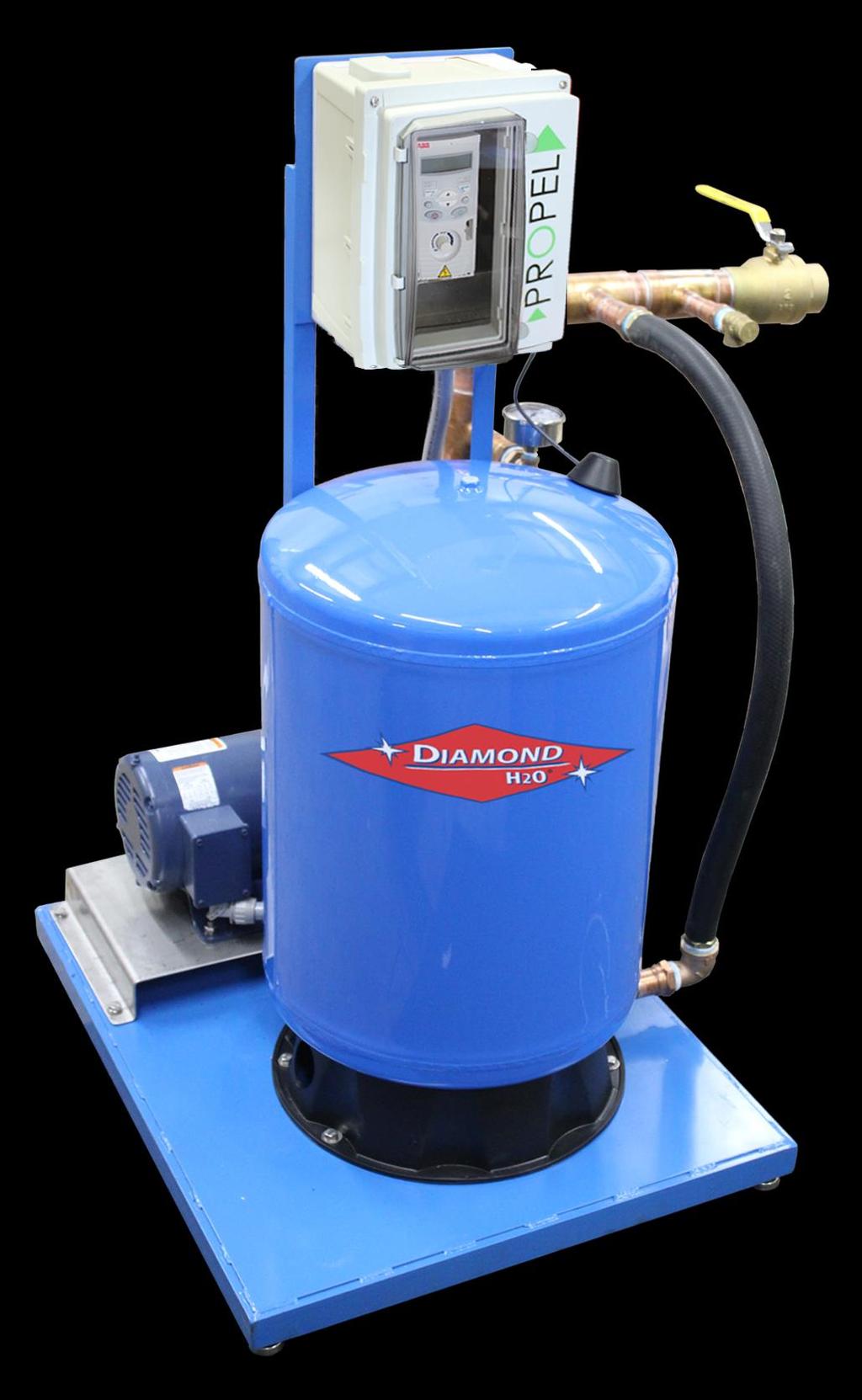
2 Set Up Instructions for DVFP Inspect the packaging of the equipment to confirm that nothing was damaged during shipping. Remove the system from the packaging. Make sure everything is included and without damage. Below is a checklist with everything you should have received. The system will already be assembled and should arrive in one piece. 1) Pump (Figure 1) 2) Variable Frequency Drive (VFD) (Figure 2) 3) Pressure Tank (Figure 3) 4) Plumbing Figure 1: Pump Figure 2: VFD Figure 3: Pressure Tank Call Diamond H2O right away if anything is missing. Contact the freight company immediately if anything is damaged. Diamond H2O will not be liable for any damage received after shipping. Packaged By: Received By: Date: Date: Table 1: System Specifications Model HP Suction Discharge psi DVFP " 1.5" 70 gpm DVFP " 1.5" 100 gpm DVFP " 2" 140 gpm 1. AWG will change depending on length of wire (values are for a max 300ft from input). 14 AWG wire can be used for any system using less than 100ft of wire from power supply. 2. With properly-sized circuit breakers, the Drive is protected from short circuit on the input and the output. 3. Minimum 240V generator size. pg. 2
3 Additional Pressure (psi) DVFP Series Variable Frequency Drive - Product Manual DVFP DVFP-70 DVFP Flow Rate (gpm) Figure 4: DFVP Sizing Recommendations Warnings All installation, service work, and inspections must be done by a qualified electrician. Risk of highvoltage electrical shock from EMI/RFI filter inside drive. Can shock, burn or kill if the front cover of the PENTEK INTELLIDRIVE is open or removed while power is connected to the Drive or the Drive is running. The front cover of the Drive must be closed during operation. Make all wiring connections, then close and fasten the cover before turning on power to drive. NEVER open the box when power is connected to Drive. Before doing any service or maintenance inside Drive or when connecting or disconnecting any wires inside Drive: A. DISCONNECT power. B. WAIT 5 minutes for retained voltage to discharge. C. Open box. Before starting any wiring or inspection procedures, check for residual voltage with a voltage tester. NEVER o connect power wiring to Drive before mounting the box. o handle or service Drive with wet or damp hands. Always make sure hands are dry before working on Drive. o reach into or change the cooling fan while power is applied to Drive. o touch the printed circuit board when power is applied to Drive. pg. 3

4 Warnings continued Do not modify equipment. Do not use power factor correction capacitors as they will damage both motor and PENTEK INTELLIDRIVE. Do not remove any parts unless instructed to do so in Owner s Manual. Do not use a magnetic contactor on Drive for frequent starting/stopping. Do not install or operate Drive if it is damaged or parts are missing. Before starting Drive that has been in storage, always inspect it and test operation. Do not carry out a megger (insulation resistance) test on the control circuit of the Drive. Do not allow loose foreign objects which can conduct electricity (such as screws and metal fragments) inside Drive box at any time. Do not allow flammable substances (such as oil) inside Drive box at any time. Ground Drive according to the requirements of the National Electrical Code Section 250, IEC 536 Class 1, or the Canadian Electrical Code (as applicable), and any other codes and ordinances that apply. Setup Instructions 1. Place the System near a water source and a power source. Decide where you would like to place the system. Ideally, it should be very close to the water source and within 25 feet of a circuit breaker. The VFD should be mounted on the wall with a few inches of clearance on every side of the VFD. This will allow free air flow to the unit. 2. Connect the Pump to the Water Source System piping should be at least one commercial pipe size larger than pump connections and flow velocity should not exceed eight (8) feet per second. In pool installation, flow velocity should not exceed six (6) feet per second. The inlet of the pump is shown in Figure 4. Follow all local codes. Pump Outlet Pump Inlet Figure 5: Pump Diagram pg. 4

 to the circuit breaker. 1. Carefully remove the cover from the VFD Enclosure 2. Inspect the system to verify the wiring is set up correctly. 1. Check that the pump is wired to the U, V, and W lines of the VFD controller.")
5 A. Pipe or tube a line from the Water Source to the Pump Inlet. a. Take Care to align piping with pump case. Misalignment or excessive pipe strain can cause distortion of pump components resulting in rubbing, breakage, and reduced pump life. B. Make sure there is no pressure on the connections. a. Support the pipe so it doesn t affect the connection to the pump. b. Check the pump alignment. C. Follow the recommendations in Figure 6 when attaching the piping. Figure 6: Plumbing recommendations 3. Connect the variable frequency drive (VFD) to the circuit breaker. 1. Carefully remove the cover from the VFD Enclosure 2. Inspect the system to verify the wiring is set up correctly. 1. Check that the pump is wired to the U, V, and W lines of the VFD controller. 2. Check that three wires are connected from the R, S, and T lines of the VFD Controller to the Fuse block. pg. 5
 wire of the pressure transducer to")


6 2. 1. U (T1), V (T2), W (T3) 3. Connect the positive (red, DIN terminal 1) wire of the pressure transducer to the 24V terminal of the VFD, the negative (black, DIN terminal 2) wire to the AI terminal of the VFD, and the ground wire of the pressure transducer to a ground. 4. Connect GND to GND and NO as shown below. Connect 24V to COM as shown below. 5. Set the AI Type Selection switch to ma (I). 6. Connect the power to the VFD. Set to I Pressure Transducer pg. 6
7 4. Set the Pressure Tank Pressure The pressure tank should be set to 70% of the desired line pressure. For example, if the desired pressure was 60psi, the pressure tank should be set to 42psi. 5. Program the DVFP Left Soft Key Loc/Rem Key Stop Key Right Soft Key Fwd/Rev Key Start Key Potentiometer Up/Down Keys The flow chart below displays how to navigate through the different modes of the VFD. pg. 7
8 Startup A. Program PID Control Data 1. From Output Mode, press the (right soft key) to enter the main menu. 2. Use the keys until the display shows Par L and press 3. From here, you should be able to cycle through parameters in the long menu using the keys. 4. Set each parameter in Table 3 to the corresponding values. For each parameter: 1. Use the keys to select the parameter 2. Press and hold (right soft key) until the value is show and is displayed 3. Use the keys to edit the value 4. Save the value by pressing (right soft key) 1. Table 2: Mandatory Programming/Verficationy) Parameter DH2O Description Value Application Macro (Set to PID) Motor Nominal Voltage Motor Nominal Current Motor Nominal Frequency Motor Nominal Speed (rpm) Motor Nominal Power (kw/hp) EXT1 Commands (Set to DI1) EXT2 Commands (Set to Keypad) Motor Direction (1=forward, 2=reverse, 3=request) Keypad Ref Select (1=Hz, 2=%) EXT1/EXT2 SEL (7=EXT2 active) REF1 Select (1=AI1, analog input 1) REF1 MIN (min value, Hz, for ref1) REF1 MAX (max value, Hz) REF2 Select (selects signal source for REF2, 19=PID1OUT) REF2 Min (min ref2 value, 0-100%) REF2 Max (max ref2 value, 0-100%) Loc Ref Source (0=potentiometer) Constant Speed Select (Selects constant speed signal, 0=not selected) Constant speed Constant speed Minimum AI1 (0-100%) Maximum AI1 (0-100%) Filter time constant AI1 ( s) Relay Output1 (3=inverted fault) RO 1 ON DELAY pg. 8
9 RO 1 OFF DELAY RUN ENABLE (0=not selected) PARAMETER LOCK (1=open) PASS CODE FAULT RESET SEL (0=keypad) LOCAL LOCK (0=not selected) PARAM SAVE (0=done) DISPLAY ALARMS (0=none) PARAMETER VIEW (1=flashdrop) FREQ INPUT MIN (0 Hz) FREQ INPUT MAX (1000 Hz) FILTER FREQ IN ( s) GAIN (High gain may cause speed oscellation) INTEGRATION TIME (seconds of integration time) DERIVATION TIME (seconds of derivation time) PID DERIV FILTER (filter time constant in seconds) ERROR VALUE INV (0=no) UNITS (4=%) UNIT SCALE % VALUE % VALUE SET POINT SEL (19=internal) INTERNAL SETPNT (desired pressure set point in %, equivalent to psi) SETPOINT MIN SETPOINT MAX FBK SEL (1=ACT1) FBK MULTIPLIER ACT1 INPUT (1=AI1) ACT2 INPUT (1=AI1) ACT1 MINIMUM (%) ACT1 MAXIMUM (%) ACT2 MINIMUM (%) ACT2 MAXIMUM (%) SLEEP SELECTION (7=internal) PID SLEEP LEVEL (unit will go to sleep when pump runs less than 45Hz) PID SLEEP DELAY (time pump needs to run below sleep level before controller goes to sleep) WAKE-UP DEV (When the pressure drops below this %, controller wakes up) WAKE-UP DELAY (seconds) pg. 9
10 A detailed description of all of the parameters can be found in the ABB manual. B. Start the System, verify that the pump is primed, the wires are installed correctly. 1. Press the Run Key. 2. If pump impeller is not running in correct direction, press forward/reverse key. pg. 10
DVFP Series Variable Frequency Drive - Product Manual. pg. 1
 pg. 1 Set Up Instructions for DVFP Inspect the packaging of the equipment to confirm that nothing was damaged during shipping. Remove the system from the packaging. Make sure everything is included and
User s Manual. ACS550-PD 3R Irrigation Packaged Drive Supplement to ACS550-U1 User s Manual
 User s Manual ACS550-PD 3R Irrigation Packaged Drive Supplement to ACS550-U1 User s Manual 2 ACS550-PD 3R Irrigation Packaged Drive ACS550 Drive Manuals GENERAL MANUALS ACS550-U1 User s Manual (1 200 HP)
User Manual. Solar Inverter for Water Pump
 User Manual Solar Inverter for Water Pump SP Revival Series Version: 1.2 Table Of Contents ABOUT THIS MANUAL... 1 Purpose... 1 Scope... 1 SAFETY INSTRUCTIONS... 1 Inspection... 1 Installation... 1 Operation...
User Manual. 2.2KW/7.5KW/11KW Solar Inverter for Water Pump. Version: 1.8
 User Manual 2.2KW/7.5KW/11KW Solar Inverter for Water Pump Version: 1.8 Table Of Contents ABOUT THIS MANUAL... 1 Purpose... 1 Scope... 1 SAFETY INSTRUCTIONS... 1 Inspection... 1 Installation... 1 Operation...
Pump Data Sheet - Patterson HVAC Pumps Company: Intermountain Hydron Name: Cache County Mountain Crest Date: 09/24/2018
 Pump Data Sheet - Patterson HVAC Pumps Company: Intermountain Hydron Name: Cache County Mountain Crest Date: 09/24/2018 Tags: P-8 1800RPM Premium Efficient Motor 460/3/60 Pump and Motor Weight: 183lbs
PDS100 Programmable Dispensing System SAFETY INSTRUCTIONS
 PDS100 Programmable Dispensing System INSTRUCTION MANUAL SAFETY INSTRUCTIONS Before using any Fluid Metering, Inc. product read the following safety instructions as well as specific product specifications
P216 Series Condenser Fan Speed Controller
 P216 Series Condenser Fan Speed Controller Installation Instructions P216xxx-x Part No. 24-85895-18, Rev. D Issued 27 August 2015 Applications Refer to the QuickLIT website for the most up-to-date version
SP6R Level Controller Operation Manual
 SP6R Level Controller Operation Manual www.sjerhombus.com SP6R LEVEL CONTROLLER INTRODUCTION SJE-Rhombus, an industry leader in water and wastewater pump controls, introduces the SP6R Level Controller.
User Manual. 2.2KW LS (Low PV Input Range) Solar Inverter for Water Pump. Version: 1.1
 Solar Inverter for Water Pump. Version: 1.1") User Manual 2.2KW LS (Low PV Input Range) Solar Inverter for Water Pump Version: 1.1 Table Of Contents ABOUT THIS MANUAL... 1 Purpose... 1 Scope... 1 SAFETY INSTRUCTIONS... 1 Inspection... 1 Installation...
User Manual 2.2KW LS (Low PV Input Range) Solar Inverter for Water Pump Version: 1.1 Table Of Contents ABOUT THIS MANUAL... 1 Purpose... 1 Scope... 1 SAFETY INSTRUCTIONS... 1 Inspection... 1 Installation...
SmartVFD Disconnect Panel Assemblies
 SmartVFD Panel Assemblies INSTALLATION INSTRUCTIONS APPLICATION Only The SmartVFD Panel Assemblies channel electrical power either through or around the variable frequency drive (VFD). INSTALLATION When
Baltimore Aircoil Company
 Baltimore Aircoil Company VFD Startup Guide TABLE OF CONTENTS: A. Verifying Power and Control Wiring...1 B. Setting the VFD Parameters...2 C. Reentering Startup Wizard After Initial Setup...5 D. Starting
ICON SERIES IDRIVE. Intelligent Constant Pressure. Water Supply Controller User Manual. idrive
 ICON SERIES IDRIVE Intelligent Constant Pressure Water Supply Controller User Manual idrive1150-240 CONTENTS PREFACE 3 1. PRODUCT DESCRIPTION 4 1.1 Functions Description 4 1.2 Model List 4 1.3 Nameplate
Installation/Fonctionnement/Pièces Pour plus de renseignements concernant l utilisation, l installation ou l entretien,
 OWNER S MANUAL PENTEK INTELLIDRIVE NOTICE D UTILISATION PENTEK INTELLIDRIVE MC MANUAL DEL USUARIO PENTEK INTELLIDRIVE PID10, PID20, PID30, PID50 Installation/Operation/Parts For further operating, installation,
INVERTER INSTRUCTION MANUAL. Relay output function. Plug-in option FR-A7AR PRE-OPERATION INSTRUCTIONS INSTALLATION AND WIRING RELAY OUTPUT
 INVERTER Plug-in option FR-A7AR INSTRUCTION MANUAL Relay output function PRE-OPERATION INSTRUCTIONS INSTALLATION AND WIRING RELAY OUTPUT 1 2 3 Thank you for choosing this Mitsubishi Inverter plug-in option.
Mitsubishi Electric Automation Instruction Manual FR-A5AC-01
 Mitsubishi Electric Automation Instruction Manual FR-A5AC-01 AC Input Interface Option Unit NOTE: CAUTION: WARNING: NOTES, CAUTIONS AND WARNINGS Notes are used to provide additional detail about a procedure.
Short User s Manual ACS310. Table of contents. Safety. Mechanical installation. Electrical installation. Start-up and control with I/O
 Short User s Manual ACS310 Table of contents Safety Mechanical installation Electrical installation Start-up and control with I/O List of related manuals DRIVE MANUALS Code (EN) ACS310 Short User s Manual
VARIABLE SPEED BOOSTER SYSTEMS AURORA INTELLIBOOST WITH INTELLIMANAGER. Distributed by Flow-Tech Industries
 AURORA INTELLIBOOST WITH INTELLIMANAGER VARIABLE SPEED BOOSTER SYSTEMS Certified to NSF/ANSI 61-G AURORA INTELLIBOOST Variable Speed Booster System Take A Leap Toward Technology The IntelliBoost Variable
Installation, Operation and Maintenance Manual
 Document 481200 VGD-100 Vari-Green Drive Installation, Operation and Maintenance Manual Please read and save these instructions for future reference. Read carefully before attempting to assemble, install,
SPD Plus INSTRUCTION MANUAL IM244R04. Models Covered: SPD Plus 230V 1Ø Input HP 230V 3Ø Input HP 460V HP 575V HP
 INSTRUCTION MANUAL IM244R04 Models Covered: SPD Plus 230V 1Ø Input 20-30 HP 230V 3Ø Input 40-60 HP 460V 40-100 HP 575V 40-100 HP C U L US SPD Plus VARIABLE SPEED PUMP CONTROL INSTALLATION AND OPERATION
TRANSISTORIZED INVERTER -INSTRUCTION MANUAL- RELAY OUTPUT FR-A5AR
 TRANSISTORIZED INVERTER -INSTRUCTION MANUAL- RELAY OUTPUT FR-A5AR Thank you for choosing the Mitsubishi transistorized inverter option unit. This instruction manual gives handling information and precautions
ACS320 drives (0.5 to 30 hp) Short form user s manual
 Short form user s manual") ABB INDUSTRIAL DRIVES ACS320 drives (0.5 to 30 hp) Short form user s manual Table of contents Safety Mechanical installation Electrical installation Start-up and control with I/O List of related manuals
ABB INDUSTRIAL DRIVES ACS320 drives (0.5 to 30 hp) Short form user s manual Table of contents Safety Mechanical installation Electrical installation Start-up and control with I/O List of related manuals
Short Form User s Manual
 Short Form User s Manual ACS310 Table of contents Safety Mechanical installation Electrical installation Start-up and control with I/O List of related manuals DRIVE MANUALS Code (EN) ACS310 Short Form
PowerFlex 400 AC Drive Guide Specification
 PowerFlex 400 AC Drive Guide Specification Adjustable Frequency Drives with Bypass 3.0 50HP @ 208V AC 3.0 350HP @ 480V AC PART 1 GENERAL 1.01 Quality Assurance A. The manufacturer shall have minimum 5
R & D SPECIALTIES SERIES 100 RO CONTROLLER USERS MANUAL. 2004, by R & D Specialties, Inc. All Rights Reserved.
 R & D SPECIALTIES 2004, by R & D Specialties, Inc. All Rights Reserved. No part of this document may be copied or reproduced in any form or by any means without the prior written permission of R & D Specialties.
Safety Instructions 1-1 Avoid unintended Start General Description 2-2
 Contents Contents 1 Safety and precautions 1-1 Safety Instructions 1-1 Avoid unintended Start. 1-1 2 Introduction 2-1 General Description 2-2 3 Supported Configuration 3-1 Introduction 3-1 Fixed-speed
AP Series Variable Frequency Drives Operation & Installation Manual
 AP Series Variable Frequency Drives Operation & Installation Manual i SAFETY MESSAGES AND WARNINGS To ensure safe and reliable operation of the AquaPhase AP Series pump converter, it is important to carefully
ABB Industrial Systems Inc. Standard Drives. ACH500-06E Effective 6/1/95
 Part 1 - GENERAL ASEA BROWN BOVERI ABB Industrial Systems Inc. Standard Drives ACH500-06E Effective 6/1/95 Sample Specification for Adjustable Frequency Drives (2 to 400 HP) for Variable Torque Applications
User Guide True RMS Multimeter Extech EX205T
 User Guide Extech EX205T True RMS Digital Multimeter Extech EX210T True RMS Digital Multimeter IR True RMS Multimeter Extech EX205T Introduction Thank you for selecting the Extech EX205T True RMS Auto-ranging
SED2 VFD NEMA Type 3R Bypass/Air Conditioner
 SED2 VFD NEMA Type 3R Bypass/Air Conditioner Description The NEMA Type 3R Bypass with Air Conditioner allows SED2 to be employed in a harsh environment. The SED2 is designed specifically for HVAC applications
VIBRATION MONITOR CX-RLY
 VIBRATION MONITOR CX-RLY MaintTech Norrkoping Airport Sweden Email: mainttech@live.se Website: www.mainttech.se 1 CX-RLY-C MODULE Version 1 1 Important User Information Solid-state equipment has operational
Table of Contents. Safety. Attention. Warnings
 Solstart Miniature Soft Starter 8-58A, 220-600V Instruction Manual Ver. 21.2. 2002 Table of Contents Page Subject 3 Starter Selection 4 Installation Notes 5 Wiring 6 Starter Settings & Start-up Procedure
Zenith DS9000 Dispensing System
 Page Date: 04/2009 Zenith DS9000 Dispensing System Installation & Operation Manual Page 2 Table of Content Introduction... 3 Control Specification... 4 Wiring Diagram... 5 Wiring Instructions... 6 Field
INGERSOLL RAND Fixed Speed/Variable Speed Conversion COMMISSIONING AND OPERATION MANUAL
 INGERSOLL RAND Fixed Speed/Variable Speed Conversion COMMISSIONING AND OPERATION MANUAL Before installing or starting this unit for the first time, this manual should be studied carefully to obtain a working
Installation and Operation Manual. ETV Platinum Plus. Electronic Tempering Valve with Safeguard WARNING
 Installation and Operation Manual ETV Platinum Plus Electronic Tempering Valve with Safeguard WARNING This Heat-Timer control is strictly an operating control; it should never be used as a primary limit
User's Guide. Digital Multimeter. Model MN42
 User's Guide Digital Multimeter Model MN42 Introduction Congratulations on your purchase of the Extech MN42 MultiMeter. The MN42 offers AC/DC Voltage, DC Current, and Resistance testing. Proper use and
Pump Quickstart Guide
 Pump Quickstart Guide Wiring Warning: Input, Output and Control wiring must be in separate conduits Note: Do not wire any wire to the DC bus P1, P2 & N terminals. VFD Only Verify correct input voltage
Model 2460-KIT. Screw Terminal Connector Kit. Description / September 2014 *P * 1
 Keithley Instruments 28775 Aurora Road Cleveland, Ohio 44139 1-800-935-5595 http://www.keithley.com Model 2460-KIT Screw Terminal Connector Kit Description The Model 2460-KIT Screw Terminal Connector Kit
User s Manual ACS Drives ( kw) ACS550-U1 Drives (1 150 HP)
 ACS550-U1 Drives (1 150 HP)") Drive IT Low Voltage AC Drives User s Manual ACS550-01 Drives (0.75 110 kw) ACS550-U1 Drives (1 150 HP) 2 ACS550 User s Manual ACS550 Drive Manuals GENERAL MANUALS ACS550-01/U1 User's Manual (0.75 110
Drive IT Low Voltage AC Drives User s Manual ACS550-01 Drives (0.75 110 kw) ACS550-U1 Drives (1 150 HP) 2 ACS550 User s Manual ACS550 Drive Manuals GENERAL MANUALS ACS550-01/U1 User's Manual (0.75 110
SED2 Variable Frequency Drives with Electronic (E) Bypass Options
 Bypass Options") SED2 Variable Frequency Drives with Electronic (E) Options Description The E- Options are companion packages for the family of SED2 Variable Frequency Drives (s). For information on the family of SED2
SED2 Variable Frequency Drives with Electronic (E) Options Description The E- Options are companion packages for the family of SED2 Variable Frequency Drives (s). For information on the family of SED2
4/8/ nd Annual OTCO WW Workshop W/WW Product Overview ACQ550. ABB Slide 1
 4/8/2015 52 nd Annual OTCO WW Workshop W/WW Product Overview ACQ550 Slide 1 Drive Basics Why Use Adjustable Speed Drives? Reduced Energy Consumption Improved Process Control / Efficiency Increased Product
Sidewinder Pumps Inc. AC C1D2 Timer/Controller
 Sidewinder Pumps Inc. AC C1D2 Timer/Controller Page 1 of 14 Rev 4/26/17 Table of Contents 1. Warnings --------------------------------------------------------------------------------------------------
FLÄKTGROUP OFFERS A WIDE RANGE OF PER- MANENT MAGNET MOTORS (PM) AND FREQUENCY CONVERTERS FOR PLUG FANS. POWER RANGE IS FROM 0,8 KW TO 15 KW.
 AND FREQUENCY CONVERTERS FOR PLUG FANS. POWER RANGE IS FROM 0,8 KW TO 15 KW.") CENTRIFLOW PUR 3D (A, PLUG B, C, D) FAN GMPM FC101 AND SLIDE IN FREQUENCY ROTOR CASSETTE CONVERTER QUICK GUIDE FLÄKTGROUP OFFERS A WIDE RANGE OF PER- MANENT MAGNET MOTORS (PM) AND FREQUENCY CONVERTERS
CENTRIFLOW PUR 3D (A, PLUG B, C, D) FAN GMPM FC101 AND SLIDE IN FREQUENCY ROTOR CASSETTE CONVERTER QUICK GUIDE FLÄKTGROUP OFFERS A WIDE RANGE OF PER- MANENT MAGNET MOTORS (PM) AND FREQUENCY CONVERTERS
INSTALLATION, OPERATING AND MAINTENANCE INSTRUCTIONS
 FORM 31003-C INSTALLATION, OPERATING AND MAINTENANCE INSTRUCTIONS PRESSURE CONTROL OPTION WITH ECM MOTORS CARNES COMPANY 448 S. Main St., P. O. Box 930040, Verona, WI 53593-0040 Phone: (608)845-6411 Fax:
GOLANDER PUMP. Operation Manual. For Microflow Variable-Speed Peristaltic Pump BT50S/BT102S.
 GOLANDER PUMP Operation Manual For Microflow Variable-Speed Peristaltic Pump BT50S/BT102S info@golanderpump.com http://golanderpump.com 1-678-587-8806 Contents Safety Cautions... 1 1 Description... 1 2
Status line The top line of the LCD display shows the basic status information of the drive.
 Control panels 91 Status line The top line of the LCD display shows the basic status information of the drive. LOC 49.1Hz LOC MAIN MENU 1 No. Field Alternatives Significance 1 Control location LOC Drive
Pure sine wave inverter. Product Manual
 Product Manual The inverter Installer must be professional, for the high pressure in the inverter, no-professional person please do not open it. The inverter should be installed at a dry, well ventilated
Wise HP33 THREE PHASE HIGH PRECISION AVR SURVO-MOTOR AUTOMATIC VOLTAGE STABILIZER
 Wise HP33 THREE PHASE HIGH PRECISION AVR SURVO-MOTOR AUTOMATIC VOLTAGE STABILIZER LEN.MAN.STA.111 Rev.4.00/2010 CONTENTS 1. SAFETY INSTRUCTIONS 1 2. INTRODUCTION 2 3. FRONT PANEL AND CONNECTION BOARD 3
MiG2 CONTROLLERS. 2 & 4 Stage General Purpose Controllers, with Air-conditioning Facilities
 MiG2 CONTROLLERS 2 & 4 Stage General Purpose Controllers, with Air-conditioning Facilities The MiG2 controllers incorporate: 2 Inputs (Configurable as Resistive, 0 10V, 0 20mA or 4 20mA) 2 or 4 Relay Outputs
PROGRAMMING MANUAL IM262R00. AQUAVAR Intelligent Pump Controller START-UP GENIE PROGRAMMING MANUAL
 PROGRAMMING MANUAL IM262R00 AQUAVAR Intelligent Pump Controller START-UP GENIE PROGRAMMING MANUAL TABLE OF CONTENTS Introduction 3 Chapter 1: Motor 4 Chapter 2: Application 5 2.1. Single Pump 5 2.2. Constant
Instruction Manual. M Pump Motor Controller. For file reference, please record the following data:
 Instruction Manual M Pump Motor Controller For file reference, please record the following data: Model No: Serial No: Installation Date: Installation Location: When ordering replacement parts for your
Plasma Panel Replacement Guide DU-42PX12X
 Plasma Panel Replacement Guide DU-42PX12X Panel Replacement: At this point, the panel has been determined to be defective and replacement is necessary. Upon receiving the replacement panel, it must be
VECTOR INVERTER -INSTRUCTION MANUAL- HIGH RESOLUTION ANALOG INPUT / EXTRA CONTACT INPUT / THERMISTOR INTERFACE FR-V5AX
 VECTOR INVERTER -INSTRUCTION MANUAL- HIGH RESOLUTION ANALOG INPUT / EXTRA CONTACT INPUT / THERMISTOR INTERFACE FR-V5AX Thank you for choosing the Mitsubishi vector inverter option unit. This instruction
PC-3000x PC-3000xC PUMP CONTROLLER. User Manual 844-4PRIMEX ( ) WATER SYSTEM INTEGRATOR AND CONTROLS PROVIDER
 WATER SYSTEM INTEGRATOR AND CONTROLS PROVIDER") PC-3000x PC-3000xC PUMP CONTROLLER User Manual WATER SYSTEM INTEGRATOR AND CONTROLS PROVIDER 844-4PRIMEX (477-4639) WWW.PRIMEXCONTROLS.COM PRIMEX TABLE OF CONTENTS Warnings... 1 Introduction and Specifications...
PC-3000x PC-3000xC PUMP CONTROLLER User Manual WATER SYSTEM INTEGRATOR AND CONTROLS PROVIDER 844-4PRIMEX (477-4639) WWW.PRIMEXCONTROLS.COM PRIMEX TABLE OF CONTENTS Warnings... 1 Introduction and Specifications...
4-step Chiller and Heat Pump Controller
 4-step Chiller and Heat Pump Controller Technical Data Sheet GENERAL DESCRIPTION MODELS CODE MODEL DESCRIPTION MW324000 ECH 420 HEAT PUMP WITH 4 STEPS/ 2 CIRCUITS + MODBUS MW324005 ECH 420/V WITH SCREW
Pump-Down Controller MODEL mA Input Scalable 4-20mA Output Duplex Pump Alternation Hand-Off-Auto Controls Dual Run-time Meters
 DESCRIPTION Pump-Down Controller Input Scalable Output Duplex Pump Alternation Hand-Off-Auto Controls Dual Run-time Meters The Model 4052 Pump-Down Controller provides total control for duplex pumping
Modified Sinewave Series. Power Inverter 1000/1500 MW 1210, MW1215. True Sinewave Power Inverter 1000/2000 SW 1210, SW 1220.
 Modified Sinewave Power Inverter 1000/1500 MW 1210, MW1215 True Sinewave Power Inverter 1000/2000 SW 1210, SW 1220 Owner s Manual Modified Sinewave Series True Sinewave Series 1. INTRODUCTION Thank you
AE R6 July 2018 Electronic Unit Controller
 July 2018 Electronic Unit Controller TABLE OF CONTENTS Safety... 3 Safety Instructions... 3 Safety Icon Explanation... 3 Instructions Pertaining to Risk of Electrical Shock, Fire, or Injury to Persons...
700 SERIES DPC DUPLEX PUMP CONTROLLER INSTRUCTION MANUAL
 1 700 SERIES DPC DUPLEX PUMP CONTROLLER INSTRUCTION MANUAL VISIT OUR WEBSITE SIGMACONTROLS.COM 700 DPC MANUAL 072114 2 TABLE OF CONTENTS INTRODUCTION 3 Ordering Information Specifications Features WIRING
When any of the following symbols appear, read the associated information carefully. Symbol Meaning Description
 Uni-I/O Modules Installation Guide UID-0808R, UID-0808T, UID-1600,UID-0016R, UID-0016T Uni-I/O is a family of Input/Output modules that are compatible with the UniStream control platform. This guide provides
IO-DI8-TO8 I/O Expansion Module 8 Inputs, 8 Outputs
 IO-DI8-TO8 I/O Expansion Module 8 Inputs, 8 Outputs The IO-DI8-TO8 is an I/O expansion module that can be used in conjunction with specific Unitronics OPLC controllers. The module offers 8 digital inputs,
Control Box Setup - PRSalpha
 888-680-4466 ShopBotTools.com Control Box Setup - PRSalpha Copyright 2016 ShopBot Tools, Inc. page 1 Copyright 2016 ShopBot Tools, Inc. page 2 Parts List: Hooking Up a PRSalpha Gantry Tool Powering the
SMVector Additional I/O Module Installation and Operation Manual
 SMVector Additional I/O Module Installation and Operation Manual About These Instructions This documentation applies to the optional Additional I/O module for the SMVector inverter and should be used in
Operating instructions. Speed monitor D / / 2014
 Operating instructions Speed monitor D200 80005257 / 00 05 / 2014 Contents 1 Preliminary note...4 1.1 Symbols used...4 1.2 Warning signs used...4 2 Safety instructions...5 2.1 General...5 2.2 Target group...5
VLT Line Filter MCC 107 EMC Filter Series VLT Midi Drive FC 280 (K1 K3)
") These instructions provide technical and installation information for the MCC 107 EMC filter series. Only Danfoss qualified personnel is allowed to install this equipment. The personnel must be familiar
These instructions provide technical and installation information for the MCC 107 EMC filter series. Only Danfoss qualified personnel is allowed to install this equipment. The personnel must be familiar
IO-PT4. Component identification. User safety and equipment protection guidelines. Unitronics Industrial Automation Systems 1
 IO-PT4 I/O Expansion Module 4 PT100 Inputs (-50 to 460 C) The IO-PT4 is an I/O expansion module that can be used in conjunction with specific Unitronics OPLC controllers. The module offers 4 PT100 inputs
Voltage Current Front-mounting bracket
 Switching Power Supply S8PS Compact DIN-Rail Mounting Industrial Power Supplies with Capacities Up to 600 W Models range from 0 W to 600 W. Universal input: voltage range 0 to 240 VAC. Power Factor Correction
User's Guide. MiniTec TM Series Model MN25 MultiMeter
 User's Guide MiniTec TM Series Model MN25 MultiMeter Warranty EXTECH INSTRUMENTS CORPORATION warrants this instrument to be free of defects in parts and workmanship for one year from date of shipment (a
When any of the following symbols appear, read the associated information carefully. Symbol Meaning Description
 Uni-I/O Wide Modules Installation Guide UID-W1616R, UID-W1616T Uni-I/O Wide is a family of Input/Output modules that are compatible with the UniStream control platform. Wide Modules are 1.5 times as wide
Owner's Manual. True RMS Multimeter. Model No Safety Operation Maintenance Español
 Owner's Manual True RMS Multimeter Model No. 82023 CAUTION: Read, understand and follow Safety Rules and Operating Instructions in this manual before using this product. Safety Operation Maintenance Español
CLEVELAND CONTROLS MODEL 6650 DIGITAL MANOMETER INSTRUCTION MANUAL DM
 CLEVELAND CONTROLS MODEL 6650 DIGITAL MANOMETER INSTRUCTION MANUAL DM-6650.02 1 Instruction Manual DM-6650.02 TABLE OF CONTENTS I.0 INTRODUCTION 3 1.1 General Description... 3 1.2 Specifications... 3 1.3
Manual FC 3500 DC Fan Control
 Manual FC 3500 DC Fan Control Description: FC 3500 DC Type: Manual File: Do150304 FC 3500 DC V12 EN.docx VDH Products BV Pages: By: Initials: 23 BVDB Doc.no: Version: Date: 150304 1.2 15-04-2015 Table
When any of the following symbols appear, read the associated information carefully. Symbol Meaning Description
 Uni-I/O Modules Installation Guide UIA-0402N Uni-I/O is a family of Input/Output modules that are compatible with the UniStream control platform. This guide provides basic installation information for
BOP QUICK START GUIDE 100W, 200W, 400W. KEPCO An ISO 9001 Company. BIPOLAR OPERATIONAL POWER SUPPLY WARNINGS I INTRODUCTION II SAFETY.
 QUICK START GUIDE I INTRODUCTION KEPCO An ISO 9001 Company. BIPOLAR OPERATIONAL POWER SUPPLY 1.1. SCOPE OF MANUAL. This Quick Start Guide covers simple installation and local operation of the Kepco 100W,
BS 287 DUAL CHANNEL POWER SUPPLY. User Manual. January 2017 V1.0
 BS 287 DUAL CHANNEL POWER SUPPLY User Manual January 2017 V1.0 Table of contents 1.0 SAFETY INSTRUCTIONS... 3 2.0 GENERAL DESCRIPTION PS 289... 4 3.0 MECHANICAL INSTALLATION... 5 4.0 MAINS POWER & SAFETY
DANGER DANGER: is used in this manual to warn of high voltages capable of causing shock, burns, or death.
 Installation/Operation Manual TABLE OF CONTENTS Page UNPACKING AND INSTALLATION Unpacking and Preliminary Inspection...2, 3 Model Number...9 LOCATION CONSIDERATIONS Environment, Equipment Performance,
RTD-W Installation Instructions
 RTD-W Installation Instructions 0V +V POWER 15-24VDC 0V S1 S2 S3 0V S4 S5 S6 English RTD-W Installation Instructions 100.00 RTD-W Control Interface realtime Control Systems 24VAC/30VDC, 1A REMC P1 P2 RS485
EC centrifugal module - RadiPac
 KG9-AR- ebm-papst Mulfingen GmbH & Co. KG Bachmühle D-7467 Mulfingen Phone +49 8 8- Fax +49 8 8- info@de.ebmpapst.com www.ebmpapst.com Limited partnership Headquarters Mulfingen County court Stuttgart
P216. Condenser fan speed controller. Product bulletin. Features
 P216 Condenser fan speed controller Product bulletin These controllers are designed for speed variation of single phase motors, especially for fan speed control on air cooled condensers. Head pressure
FR-A8AR INSTRUCTION MANUAL
 INVERTER Plug-in option FR-A8AR INSTRUCTION MANUAL Relay output function PRE-OPERATION INSTRUCTIONS INSTALLATION AND WIRING RELAY OUTPUT 1 2 3 Thank you for choosing this Mitsubishi inverter plug-in option.
User s Manual. ACS550-PD Stock 3R Irrigation Packaged Drive Supplement to ACS550-U1 User s Manual
 User s Manual ACS550-PD Stock 3R Irrigation Packaged Drive Supplement to ACS550-U1 User s Manual 2 ACS550-PD 3R Irrigation Packaged Drive ACS550 Drive Manuals GENERAL MANUALS ACS550-U1 User s Manual (1
Quick Start Guide For GVX9000 AF Drives
 Quick Start Guide For GVX9000 AF Drives June 2006 New Information 5011646300 00GQ MN04000002E June 2006 Step 1 Wiring Hazardous High Voltage HIGH VOLTAGE! Motor control equipment and electronic controllers
700 Series 200 Amp Clamp Meters
 700 Series 200 Amp Clamp Meters #61-700 #61-701 #61-702 1 2 3 6 5 7 4 8 1. Non-contact voltage (NCV) (#61-701 and #61-702) With the NCV tab on the tip of the clamp close to an AC voltage, press the NCV
GCI-5K INSTALLATION AND OPERATOR S MANUAL
 GCI-5K INSTALLATION AND OPERATOR S MANUAL Grid-tied inverter for wind Ningbo Ginlong Technologies 1 INTRODUCTION 2 SAFETY GUIDELINES AND WARNINGS 3 INSTALLATION 3.1 Selecting a location for the inverter
7032 Digital-Analog Multimeter
 7032 Digital-Analog Multimeter OPERATOR S MANUAL CONTENTS: 1. Safety precautions and procedures 1 1.1. Preliminary 1 1.2. During Use 2 1.3. After Use.. 2 2. General Description. 3 3. Preparation for Use..
MYRIAD QLC 4-CHANNEL MONITOR/CONTROLLER INSTRUCTION MANUAL
 MYRIAD QLC 4-CHANNEL MONITOR/CONTROLLER INSTRUCTION MANUAL VISIT OUR WEBSITE SIGMACONTROLS.COM MYR QLC MANUAL 013114 2 TABLE OF CONTENTS INTRODUCTION 3 Ordering Information Specifications Features WIRING
Motor Controllers AC Variable Frequency Drives Type VariFlex 3 RVLF
 AC variable speed drive for use with AC induction motors V/F control + Auto-torque compensation function Input voltage ranges: 1-ph 200~240V, 3-ph 380~480V 2 frame sizes Conforms to EMC standard EN 61800-3
Technical Tip: iqpump1000 Setup Procedure for Use with Seametrics AG2000 Flow Meter
 SUMMARY This Technical Tip provides an example set-up for a Yaskawa iqpump1000 drive and a Seametrics AG2000 Flow Meter. Features of this system example: Display flow rate Check for high or low flow rates
Nature Power Inverters. Modified Sinewave 1000w/1500w True Sinewave 1000w/2000w. Owner s Manual
 Nature Power Inverters Modified Sinewave 1000w/1500w True Sinewave 1000w/2000w Owner s Manual Modified Sinewave Series True Sinewave Series For safe and optimum performance, the Power Inverter must be
TPE 1464 Series Pressure Transducer
 TPE 1464 Series Pressure Transducer Description The KMC TPE 1464 series of pressure transducers incorporate a gauge pressure transmitter featuring low hysteresis, excellent repeatability, and longterm
CDD Carbon Dioxide Transmitter
 Introduction The OSA CO2 transmitter uses Infrared Technology to monitor CO2 levels within a range of 0 2000 ppm and outputs a linear 4-20 ma or 0-5/0-10 Vdc signal. The enclosure is designed to operate
AF-600 FP TM Fan & Pump Drive. (230V to 60HP, 460/575V to 125HP Operating Instructions
 GE AF-600 FP TM Fan & Pump Drive (230V to 60HP, 460/575V to 125HP Operating Instructions Safety Safety WARNING HIGH VOLTAGE! Frequency converters contain high voltage when connected to AC mains input power.
SED2 Variable Frequency Drives
 SED2 Variable Frequency Drives Startup Procedure and Checklist Document No. 155-718 Table of Contents Prerequisites...1 Preparing for SED2 VFD Startup...1 HVAC Startup Procedure for SED2 with Bypass Option...4
IntelliBrite Controller (For IntelliBrite Pool, Spa and Landscape Lighting Fixtures)
") IntelliBrite Controller (For IntelliBrite Pool, Spa and Landscape Lighting Fixtures) Installation and User s Guide IMPORTANT SAFETY INSTRUCTIONS READ AND FOLLOW ALL INSTRUCTIONS SAVE THESE INSTRUCTIONS
IntelliBrite Controller (For IntelliBrite Pool, Spa and Landscape Lighting Fixtures) Installation and User s Guide IMPORTANT SAFETY INSTRUCTIONS READ AND FOLLOW ALL INSTRUCTIONS SAVE THESE INSTRUCTIONS
SmartVFD Frame 8 Wiring Diagrams and Dimensional Drawings
 Smart Frame 8 Wiring Diagrams and Dimensional Drawings Smart Frame Size 8 460 Vac: 00-50 HP 08/0 Vac: 50-75 HP SPECIFICATION DATA CONTENTS Smart Frame 8 Wiring Diagrams... Frame 8, Fused Disconnect Wiring
DNG-200 LOW FOG GENERATOR USER MANUAL DNG-200 低煙機使用說明書
 DNG-200 LOW FOG GENERATOR USER MANUAL DNG-200 低煙機使用說明書 Read and save these insturctions 2008 Antari Lighting & Effects Ltd. User Manual Antari DNG-200 Low fog Generator Congratulations on the purchase
The power behind competitiveness. Delta Infrasuite Power Management. Power Distribution Unit. User Manual.
 The power behind competitiveness Delta Infrasuite Power Management Power Distribution Unit User Manual www.deltapowersolutions.com Save This Manual This manual contains important instructions and warnings
NI PXIe-1062Q Power Supply Shuttle
 USER GUIDE NI PXIe-1062Q Power Supply Shuttle The NI PXIe-1062Q power supply shuttle is a replacement part for the NI PXIe-1062Q chassis. Caution This power supply is not compatible with any other National
SED2 Variable Frequency Drives Conventional Bypass (C-Bypass) Options
 Options") Submittal Sheet SED2 Variable Frequency Drives Conventional Bypass (C-Bypass) Options Description The Bypass Options are companion packages for the family of SED2 Variable Frequency Drives. For information
Submittal Sheet SED2 Variable Frequency Drives Conventional Bypass (C-Bypass) Options Description The Bypass Options are companion packages for the family of SED2 Variable Frequency Drives. For information
Vacon HVAC100 Commissioning Guide
 Vacon HVAC100 Commissioning Guide INDEX 1. Glossary of terms 2. Wiring diagrams 3. Set up procedures a. Motor settings input b. Low level start, analogue input speed reference in AUTO position. Low level
Switched Mode Power Supply Operating manual PAP800
 Features: Switched mode power supply Wide output 0 144Vdc Analog control by an external 0 5Vdc Power failure alarm output Master-slave connection Powerfinn PAP series is a high power, lightweight, advanced