Air Hockey v7.0 Controller PCB Air Hockey 10v Transformer
|
|
|
- Sabrina Bradford
- 6 years ago
- Views:
Transcription

1 KNOWN ISSUES SORTED BY BOARD REVISION DYNAMO HOCKEY PCBs LISTED IN THIS WORKSHEET are no longer available for purchase or serviced by the manufacturer. Most tables can be upgraded to Dynamo s latest v7.0 PCB, giving your table all the current functionality and programming, and a board with no prior repair history. Also, Board-level components listed on this guide are not available from Valley-Dynamo, and may no longer be available at all as some date back more than 20 years. Boards that old probably should be replaced in the event of a problem. When installing the v7.0 PCB, the 12-volt Transformer on your Dynamo table will need to be replaced with a 10-volt transformer. YOUR GAME WILL NOT WORK PROPERLY AND MAY BE DAMAGED if attempting to operate a v7.0 PCB and a 12-volt transformer. Order these parts Air Hockey v7.0 Controller PCB Air Hockey 10v Transformer from your Valley-Dynamo distributor or at
2 VERSION 2.4 A-C v2.4 A-C version boards are no longer repairable and will need to be replaced if they fail. PROBLEM: The game cuts off soon after it is coined up and will not start another game until the game is turned off and back on. This can happen every game or once in a while. An additional symptom would be that it will not score. CAUSE: The board is programmed to end the game if it detects one of the 3 input switches closed for more than 1 minute. The unit is also programmed to only accept one input at a time (that is why it will not score). Please note that all input switches need to be wired Normally Open. SOLUTION: You will need an Ohmmeter to isolate, which of the 3 switches is closed. 1. Turn the A/C power off and unplug the game from the power source. 2. Unplug the 15-pin edge connector from the main board. 3. Using your meter, check for a closed circuit on the left score switch between pins F (pink wire) and 6 (gray wire). 4. Using your meter, check for a closed circuit on the right score switch between pins H (orange wire) and 7 (gray wire). 5. Using your meter, check for a closed circuit on the coin switch between pins J (brown wire) and 8 (blue wire). If you did not find 1 of the 3 closed then you may have a switch that is momentarily getting stuck. A. Check to make sure the Coin mech is returning to the vend position every time. B. Remove both metal goal covers and then slightly pull the actuator wire away from the end wall. Next trim off about 1/16 to 1/8 from the tip of the actuator wire. Replace the covers. The next steps will reference the left score switch as the closed circuit. If you found a closed circuit use the following steps: C. Go to the left end of the hockey table and remove the goal cover. D. Recheck the circuit to see if you still have a closed circuit. If your circuit is open now and you did not have a stuck puck or a foreign object stuck in the end goal area refer to step B. If you did have something stuck your problem should be fixed. E. If you still have a closed circuit, make sure the switch is wired properly. The pink wire should be going to the connector marked NO (normally open) and the gray wire should be connected to the pin marked COM (common). F. If the wiring is correct, disconnect the Pink wire from the switch and again check for a closed circuit. If it shows open now, replace the switch. If it still shows closed, you have a short in the wiring harness. 2
3 VERSION 2.4 A-C PROBLEM: The game displays will not come on until you coin a game and the table will not score. The game also ends very soon after it is started. CAUSE: In the boards initial self-test it looks at the coin switch and will stop the boot up sequence if it sees the switch in the closed position. The reason the displays come on after you vend the coin switch is because you are opening the switch momentarily, letting the self-test complete. The unit is also programmed to only accepted one input at a time (that s why it will not score). It ends the game because the logic board monitors all 3 input switches and if one is in the closed positions over 1 minute it will end the game being played. Please note that all input switches need to be wired Normally Open. SOLUTION: You will need an Ohmmeter to isolate the problem. 1. Turn the A/C power off and unplug the game from the power source. 2. Unplug the 15-pin edge connector from the main board. 3. Using your meter, check for a closed circuit between pins J (brown wire) and 8 (blue wire). If it reads open then you have a main board problem. If your version is 2.4A you will need to purchase a new main board and display ( ). If your version is a 2.4C you will only need a new main board. If you did have a closed circuit: 1. Make sure the switch is wired correctly. The brown wire needs to be connected to pin NO (normally open) and the blue wire connected to COM (common). 2. Once you verify that the switch is wired correctly, unplug the brown wire and check to see if you have a closed switch. If it still shows a closed switch, you have a short in the wiring harness. If the circuit shows open, replace the switch. If your table were still set up with a micro switch this would be a good time to upgrade the table to a reed switch. When you order just ask for part number VERSION 5.1 PROBLEM: When you coin a game the meter starts running non stop or adds extra credits up to 99. Or The game will not start (come on) when it is coined up but the meter shows the credit. Or 3
4 When you coin a game, it gives more than one game, anywhere from Or Any combination of the three. CAUSE: The program has been altered. This can happen due to six things. 1. The game sustained a large A/C spike. 2. The game is in an area with a lot of static electricity. 3. The field ground circuit has broken. 4. IC number 93C46 is bad. 5. The micro controlled 80C31 is bad. 6. The Crystal XTAL is bad. SOLUTION: First you will need to reset the program. 1. Hold the toggle switch located on the main board in the CAL 1 position for at least 5 seconds. THE DISPLAY WILL BE COUNTING IN TENTHS OF SECONDS, WHEN THE DISPLAY READS 50 YOU CAN RELEASE THE SWITCH. 66 = the number of times you need to vend the push chute before you get a credit. 77= how long the game lasts in increments of 1 minute. 44= the number of credits shown on the coin counter per vend. 11= the number of games per credit. The factory default is: 66= 01 It only takes 1 vend on the push chute to equal one credit. 77=07 A game will last for 7 minutes. 44=01 The coin meter will only increment by 1 11=01 Only 1 game is issu VERSION 5.1 TO MAKE SURE ALL OF THE SETTINGS ARE RIGHT YOU WILL NEED TO GO THROUGH THE COMPLETE LOOP OF OPTIONS. For example, in 66 even if it currently is set to 01 you will need to toggle the switch until the display reads 01 again. 2. The display will flash the number 66 and then go to a stationary number between 01 and 99. You will need to toggle the switch into the CAL 2 position until the display shows Toggle the switch into the CAL 1 position 1 time. 4. The display will now flash 77 and then go to a stationary number between 01 and 15. You will need to toggle the switch into the CAL 2 position until the display shows Toggle the switch into the CAL 1 position 1 time. 6. The display will now flash 44 and then go to a stationary number between 01 and 99. You will need to toggle the switch into the CAL 2 position until the display shows 01. 4
5 7. Toggle the switch into the CAL 1 position 1 time. 8. The display will now flash 11 and then go to a stationary number between 01 and 99. You will need to toggle the switch into the CAL 2 position until the display shows Toggle the switch into the CAL 1 position 1 more time. The display should now be flashing Check to make sure the game will coin up correctly. 10. Turn the A/C power off and disconnect the power cord from the outlet. 11. Using an ohm meter inspect the A/C power cords field ground for an open circuit. If it shows that it is open replace the power cord. 12. Once you ve determined the power cord is good, plug the game back in and turn the power back on. Your display should show an 8 in the left segment then an 8 in the right segment followed by Try to coin up a game. If it will, then the IC 93C46 is good. If both the line cord and IC 93C46 show to be good your problem was from an A/C spike, static electricity, or a bad ground on your outlet. We suggest that you install a surge suppressor. 5
6 VERSION PROBLEM: The game will not start and 11 is flashing on the display. CAUSE: The logic board is detecting a constantly closed circuit on the right end goal. SOLUTION: 1. Remove the end goal cover. You will probably find a stuck puck or some type of foreign matter. 2. If you did find something, replace the cover and see if the game will coin. 3. If you did not find stuck objects, the next step is make sure the inside of the goal cover has a flat black 4 X 4 label or has the area painted flat black. If it does not, the optic may be reading itself. By painting the inside of the end goal with flat black paint, the problem is eliminated. 4. Turn the power off of the game and unplug it. 5. Pull off the 15-pin edge connector from the main board. 6. Using an ohm meter, check for a closed circuit on the right score optic between pins H (orange wire) and 7 (gray wire). 7. If it shows open you need to replace the main board. 8. If the circuit shows closed, remove the goal entry cover and disconnect the 4-pin connector from the optic board and recheck the circuit. 9. If it now shows open, replace the optic board ( ) 10. If the circuit still shows closed, you have a wiring problem. PROBLEM: The game will not start and 22 is flashing on the display. CAUSE: The logic board is detecting a constantly closed circuit on the left end goal. SOLUTION: 1. Remove the end goal cover. You will probably find a stuck puck or some type of foreign matter. 2. If you did find something, replace the cover and see if the game will coin. 3. If you did not find stuck objects, the next step is make sure that the inside of the goal cover has a flat black 4 X 4 label or has the area painted flat black. If it does not, the optic may be reading itself. By painting the inside of the end goal with flat black paint, the problem is eliminated. 4. Turn the game power off and unplug it. 5. Pull off the 15-pin edge connector from the main board. 6. Using an ohm meter check for a closed circuit on the right score optic between pins F (pink wire) and 6 (gray wire). 7. If it shows open, you need to replace the main board. 8. If the circuit shows closed, remove the goal entry cover and disconnect the 4-pin connector from the optic board and recheck the circuit. 6
7 9. If it now shows open, replace the optic board ( ) 10. If the circuit still shows closed, you have a wiring problem. VERSION PROBLEM: The display shows a single 8 on the left segment of the score display. CAUSE: The logic boards self-test have detected the coin circuit closed. SOLUTION: You will need an Ohmmeter to isolate the problem. 1. Turn the A/C power off and unplug the game from the power source. 2. Unplug the 15-pin edge connector from the main board. 3. Using your meter check for a closed circuit between pins J (brown wire) and 8 (blue wire). If it reads open then you have a main board problem. The board will require replacement If you did have a closed circuit: (If your table uses a reed switch instead of a micro switch skip step #4). 3. Make sure the switch is wired correctly. The brown wire needs to be connected to pin NO (normally open) and the blue wire connected to COM (common). 4. Once you verify that the switch is wired correctly unplug the brown wire and check to see if you have a closed switch. If it still shows a closed switch, you have a short in the wiring harness. If the circuit shows open, replace the switch. If your table is still set up with a micro switch this would be a good time to upgrade the table to a reed switch. When you order just ask for part number
8 VERSION PROBLEM: When you coin a game the meter starts running non stop or adds extra credits up to 99. Or The game will not start (come on) when it is coined up but the meter shows the credit. Or When you coin a game, it gives more than one game, anywhere from Or Any combination of the three. CAUSE: The program has been altered. This can happen due to six things. 1. The game sustained a large A/C spike. 2. The game is in an area with a lot of static electricity. 1. The field ground circuit has broken. 2. IC number 93C46 is bad. 3. The micro controlled 80C31 is bad. 4. The Crystal XTAL is bad. SOLUTION: First you will need to reset the program. 1. Turn the A/C power switch OFF. 2. Turn the A/C power switch back on while you hold the toggle switch located on the main board in the CAL 2 position for at least 5 seconds. 3. Hold the toggle switch down in the CAL 1 position for a minimum of 10 seconds. THE DISPLAY WILL BE COUNTING IN TENTHS OF SECONDS, WHEN THE DISPLAY PASSES 99 AND STARTS TO COUNT OVER YOU CAN RELEASE THE SWITCH. Once you have released the toggle switch the display will flash 55 one time and then display a 5 in the right display. 1. Push the toggle switch into the CAL 2 position 1 time. The display should now read a 1 in the right display. 2. Push the toggle switch down into the CAL 1 position 4 times waiting at least two seconds between each toggle. 3. The display should flash 00 then 0 back and forth in a repeat cycle. If it is not, simply push the toggle switch in the CAL 1 position a few more times. There are 4 levels in the 10-second program menu. The board will not register your closures on the toggle switch until the display has stopped flashing, that is why you need to wait at least 2 seconds between each toggle to proceed to the next level. The display should now be flashing Check to make sure the game will coin up correctly. Continued on the next page. 8
9 VERSION To eliminate possible causes, use the following steps. If you where not able to get into the program, then the problem is on the main game board. The probable failures will be the Micro Controller (80C31) or the oscillating crystal (XTAL Hz) 1. Turn the A/C power off and disconnect the power cord from the outlet. 2. Using an ohm meter inspect the A/C power cords field ground for an open circuit. If it shows that it is open, replace the power cord. 3. Once you ve determined the power cord is good, plug the game back in and turn the power back on. Your display should show an 8 in the left segment then an 8 in the right segment followed by Try to coin up a game. If it will then the IC 93C46 is good. If both the line cord and IC 93C46 show to be good your problem was from an A/C spike, static electricity, or a bad ground on your outlet. We suggest that you install a surge suppressor. 9
10 VERSION PROBLEM: The display shows an 8 in the left segment during power up and will not change. CAUSE: The logic board is reading a closed circuit on the coin switch. PROBLEM: SOLUTION: 1. Turn the A/C power off. 2. Disconnect one wire from the coin switch. 3. Turn the A/C power back on. If the game continued through the self-test and into the attract mode then you have a bad reed switch ( ). If the game still only displayed an 8. You will need an Ohmmeter to isolate the problem. 1. Turn the A/C power off and unplug the game from the power source. 2. Unplug the 15-pin edge connector from the main board. 3. Using your meter check for a closed circuit between pins J (brown wire) and 8 (blue wire). If the circuit reads closed, the problem is in the wiring. If the circuit reads open, the problem is the main board ( ). The display shows an 8 in the right display segment. CAUSE: The main board SOLUTION: The most common cause is that either CR1 or CR2 has been physically broken open. 10
11 PROBLEM: VERSION 6.11 When you coin a game the meter starts running non stop or adds extra credits up to 99. Or The game will not start (come on) when it is coined up but the meter shows the credit. Or When you coin a game, it gives more than one game, anywhere from Or Any combination of the three. CAUSE: The program has been altered. This can happen due to six things. 1. The game sustained a large A/C spike. 2. The game is in an area with a lot of static electricity. 5. The field ground circuit has broken. 6. IC number 93C46 is bad. 7. The micro controlled 80C31 is bad. 8. The Crystal XTAL is bad. SOLUTION: First you will need to reset the program. 1. Turn the A/C power switch OFF. 2. Turn the A/C power switch back on while you hold the toggle switch located on the main board in the CAL 2 position for at least 5 seconds or until the display is flashing 00/0. The display should now be flashing Check to make sure the game is coining up correctly. To eliminate possible causes, use the following steps. If you where not able to get into the program then the problem is on the main game board. The probable failures will be the Micro Controller (80C31) or the oscillating crystal (XTAL Hz) 5. Turn the A/C power off and disconnect the power cord from the outlet. 6. Using an ohm meter inspect the A/C power cords field ground for an open circuit. If it shows that it is open replace the power cord. 7. Once you ve determined the power cord is good, plug the game back in and turn the power back on. Your display should show an 8 in the left segment then an 8 in the right segment followed by Try to coin up a game. If it will then the IC 93C46 is good. If both the line cord and IC 93C46 show to be good your problem was from an A/C spike, static electricity, or a bad ground on your outlet. We suggest that you install a surge suppressor. 11
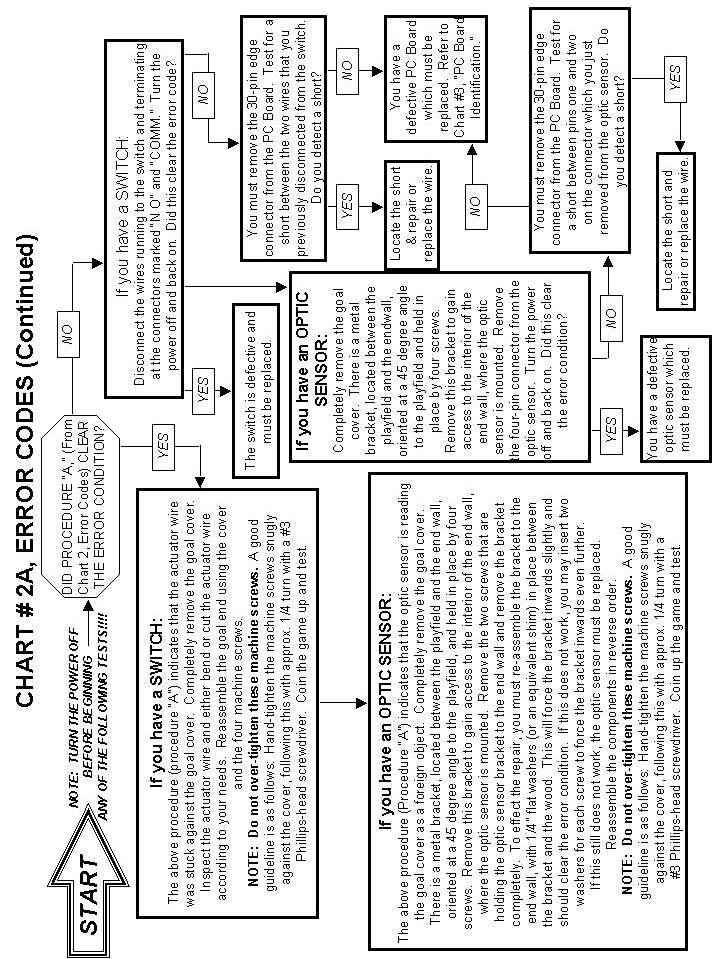
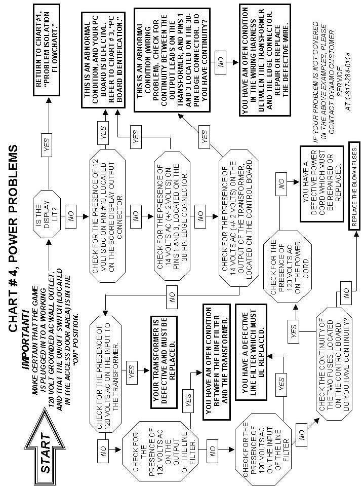
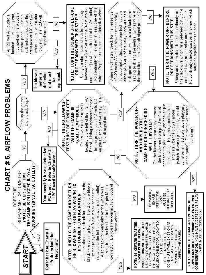
12 DYNAMO HOCKEY TROUBLESHOOTING FLOW CHARTS If you are experiencing a problem with your Dynamo Hockey table, you must first identify the type of problem in order to arrive at a solution. Most problems may be categorized as either mechanical or electronic, with electronic problems making up the majority. The following flowcharts should provide you with enough information to accomplish most simple troubleshooting tasks on your Dynamo Hockey table. Please contact the Dynamo, Ltd. Customer Service Department at , (option 2) if you have any problems not addressed in the following pages. Special note on changing PC Boards: When changing the PC board in your Dynamo Hockey game, please note the following: There are two 15-pin connectors on your board that appear to be identical. Be certain that the display unit is connected to the pin connector marked "display/score." The other pin connector (marked "MARS C-120") is used for an electronic coin comparator, which is not normally shipped as a part of your game. 12
13 13
14 14
15 15
16 16
17 17
18 18

19 19
20 20
21 21
CHAPTER Wi r i n g NOTICE:
 CHAPTER Wiring NOTICE: Information in this manual may change without notice. Midway Games West Inc. reserves the right to make improvements in equipment function, design, or components as progress in engineering
Validator Update Instructions for Rowe BC1200 $1 - $20
 Validator Update Instructions for Rowe BC1200 $1 - $20 Kit Overview The purpose of the kit is to replace the Rowe BA50 transport and stacker with a 120 volt Mars validator with a compact mask. The kit
INSTALLATION INSTRUCTIONS Model 930 EntryCheck
 SECURITY DOOR CONTROLS 3580 Willow Lane, Westlake Village, CA 91361-4921 (805) 494-0622 Fax: (805) 494-8861 www.sdcsecurity.com E-mail: service@sdcsecurity.com INSTALLATION INSTRUCTIONS Model 930 EntryCheck
Troubleshooting CHAPTER
 CHAPTER 1 1 1 1 0 1 1 0 1 1 0 1 1 0 1 1 0 1 1 0 1 1 0 1 1 1 0 1 6 0 1 1 0 1 1 0 1 0 1 10 1 0 1 1 0 1 0 1 1 0 1 0 1 1 0 1 10 Troubleshooting NOTICE: Information in this manual may change without notice.
X/Y Issues on ASP-645-1
 X/Y Issues on ASP-645-1 Issues seen with X or Y problems: A) Table will not move in X or Y when you are using the Frame Arrow buttons on the control panel. B) On power up the control panel gives Error
1%$6+2:7,0(*2/'(',7,21 1)/%/,7=*2/'(',7,21 &219(56,21.,7
/%/,7=*2/'(',7,21 &219(56,21.,7") 1%$6+2:7,0(*2/'(',7,21 1)/%/,7=*2/'(',7,21 &219(56,21.,7 C H A P T E R F I V E WIRING WARNING: Failure to reconnect ground wires or replace metal shields may result in radio frequency interference. NOTICE:
1%$6+2:7,0(*2/'(',7,21 1)/%/,7=*2/'(',7,21 &219(56,21.,7 C H A P T E R F I V E WIRING WARNING: Failure to reconnect ground wires or replace metal shields may result in radio frequency interference. NOTICE:
ELECTRICAL SUPPLY TROUBLESHOOTING QUICK GUIDE SAFETY PRECAUTIONS
 ELECTRICAL SUPPLY TROUBLESHOOTING QUICK GUIDE 1. Circuit Breaker Tripping 2. Circuit Overload 3. Short Circuit 4. Ground Fault 5. Ground Fault Circuit Interrupter (GFCI) Tripping SAFETY PRECAUTIONS Basic
Treadmill Embedded Touch Screen Won t Power Up
 Treadmill Embedded Touch Screen Won t Power Up E-TRe and E-TRxe This document contains the necessary information to troubleshoot a treadmill with an embedded touch screen that will not power up. Follow
RS3000 SERIES BILL ACCEPTORS
 Flash Diagnostic Codes RS3000 SERIES BILL ACCEPTORS INSTALLATION GUIDE s of the bill acceptor. Below is a chart that lists all the flash codes of the RS3000 Bill Acceptor and a description of each code.
SMART VEND PR & PR/PD & SLIM TROUBLESHOOTING GUIDE
 SMART VEND PR & PR/PD & SLIM TROUBLESHOOTING GUIDE MAYTAG CIRCUIT BOARD The Maytag Circuit Board Interface The Maytag CompuTrac Circuit Board was designed to work with advanced payment type of systems
1/Build a Mintronics: MintDuino
 1/Build a Mintronics: The is perfect for anyone interested in learning (or teaching) the fundamentals of how micro controllers work. It will have you building your own micro controller from scratch on
Microframe Corporation
 Microframe Corporation Series 160: Booster Amplifier Operating Manual A0160-7011 *A0160-7011* SERIES 160 INSTALLATION & SPECIFICATION GUIDE ITEM NO: A0160-7011 REVISION DATE: 04/02 Microframe Corporation
The GENIE Light Kit is ideal for introducing simple lighting projects, such as an electronic die, a wearable badge or a night-time warning system.
 Introduction 1 Welcome to the GENIE microcontroller system! The GENIE Light Kit is ideal for introducing simple lighting projects, such as an electronic die, a wearable badge or a night-time warning system.
Arrakis Systems 6604 Powell Street / Loveland, Colorado 80538
 Arrakis Systems 6604 Powell Street / Loveland, Colorado 80538 Input and Output wiring for the 150sc, 500sc, 2000sc and 2100sc audio consoles. A Input Channel Wiring (Back of Console) 6. Left Input 5. Left
Basketball Shot Clock Set LX2180 Manual
 Basketball Shot Clock Set LX2180 Manual 72 Industrial Boulevard Wrightsville, GA 31096 Phone: (800) 445-7843 Fax: (800) 864-0212 www.electro-mech.com LX2180 Revision 5 February 8, 2013 Table of Contents
EMS. Electrical Management System. Progressive Industries Incorporated Morrisville, North Carolina
 Progressive Industries Warranty Progressive warrants its products are free from defects in materials and workmanship for a period of three years. This is in lieu of all other warranties, obligations, or
Portable Gas Monitor (PGM-IR) Infrared Sensor Replacement Instruction
 Infrared Sensor Replacement Instruction") Portable Gas Monitor (PGM-IR) Infrared Sensor Replacement Instruction 3015-5508 Rev. 3 January 2018 1. Scope These instructions describe how to replace the IR sensor in the Portable Gas Monitor (example
Portable Gas Monitor (PGM-IR) Infrared Sensor Replacement Instruction 3015-5508 Rev. 3 January 2018 1. Scope These instructions describe how to replace the IR sensor in the Portable Gas Monitor (example
Table of Contents. Unpacking and Inspection Setup Loading the Media Mount the Printer on the Wall... 16
 WPL25/WHC25 Table of Contents Unpacking and Inspection... 1 Setup... 5 Loading the Media... 6 Mount the Printer on the Wall... 16 LED and Button Functions... 17 Troubleshooting... 18 Unpacking and Inspection
VMI. Technical Documentation. 600 Industrial Drive, New Bern, N.C (tel / fax /
 VMI E-Series Virtual Mixer Interface Technical Documentation 600 Industrial Drive, New Bern, N.C. 28562 (tel 252-638-7000 / fax 252-637-1285 / email@wheatstone.com ) VMI E-Series Virtual Mixer Interface
 This tutorial was written by Team Xecuter. If you use anything from this tutorial please give credits and also a direct link to this page. Also if we have made any mistakes or left anything out please
Operation Manual WARNING. Be sure to read this Operation Manual before use. Universal Space Amusement Equipment Ltd.
 WARNING Be sure to read this Operation Manual before use. Universal Space Amusement Equipment Ltd. CONTENTS 1. The company..2 2. Specifications.. 3 3. Package Contents..5 4. Installation, Fix and Transport..6
Phillips Screwdriver. Some C-128's may need a TORX ("star" point) driver (size T10)f available at Sears, and other hardware and automotive stores.
 driver (size T10)f available at Sears, and other hardware and automotive stores.") C-128 INSTALLATION Required Tools: Phillips Screwdriver. Some C-128's may need a TORX ("star" point) driver (size T10)f available at Sears, and other hardware and automotive stores. IC extractor or small,
C-128 INSTALLATION Required Tools: Phillips Screwdriver. Some C-128's may need a TORX ("star" point) driver (size T10)f available at Sears, and other hardware and automotive stores. IC extractor or small,
Secured Series: Hub Plus Kit Single Door Controller Package Installation Manual
 Secured Series: Hub Plus Kit Single Door Controller Package Installation Manual This package is designed to simplify the connections to our Secured Series Hub Plus Controller. This will translate into
Owner s Hardware Service Manual Frank Control Computer System
 Owner s Hardware Service Manual Frank Control Computer System Revision 0105 ABOUT THIS MANUAL This section describes the contents of this manual and how to use this manual effectively. It was designed
A0319. Bluetooth Wall-Dock for Distributed Audio. Intelligent Entertainment Infrastructure Security Solutions
 A0319 Bluetooth Wall-Dock for Distributed Audio Intelligent Entertainment Infrastructure Security Solutions The A0319 is an on-wall bluetooth docking station that will charge an ipod, iphone or itouch
!There are two kit models. The ZCTK-120 is designed to operate with.!the pulse output is isolated from the mains line voltage. A pull-up resistor
 CAUTION: Please make sure you have or have access to the skills necessary to assemble and use this product. Always secure the case with the included screws before applying electrical power to the power
High Voltage Power Supply (MMPS) - Troubleshooting Guide
 - Troubleshooting Guide") High Voltage Power Supply (MMPS) - Troubleshooting Guide LAST UPDATED: 09/19/2018 High Voltage Power Supply (MMPS) - Troubleshooting Guide Overview The High Voltage Power Supply (MMPS - MINIMILL Power
High Voltage Power Supply (MMPS) - Troubleshooting Guide LAST UPDATED: 09/19/2018 High Voltage Power Supply (MMPS) - Troubleshooting Guide Overview The High Voltage Power Supply (MMPS - MINIMILL Power
ES-562/564U COMBINATION CLOCK/TIMER
 142 SIERRA ST., EL SEGUNDO, CA 90245 USA (310)322-2136 FAX (310)322-8127 www.ese-web.com ES-562/564U COMBINATION CLOCK/TIMER OPERATION AND MAINTENANCE MANUAL The ES-562U/564U is a combination six digit
SCHMIDT MODEL G4 TAXIMETER PROGRAMMING MODULE OPERATORS INSTRUCTIONS. Version 5, 1 st February 2011
 SCHMIDT MODEL G4 TAXIMETER PROGRAMMING MODULE OPERATORS INSTRUCTIONS. Version 5, 1 st February 2011 The Model G4 Programming Module The Schmidt Model G4 Taximeter Programming Module is a multifunction
RAINWATCH WIRELESS RECEIVER WIRING
 RAINWATCH INSTALLATION THIS MANUAL IS DESIGNED TO LEAD YOU STEP BY STEP THROUGH THE PROCEDURES REQUIRED TO TEST, INSTALL AND USE YOUR RAINWATCH. BY FOLLOWING THESE PROCEDURES AND SETTING UP THE SYSTEM
Chapter 5 Review. Power Supplies
 Chapter 5 Review Power Supplies Name Period Date Score Write your answers in the spaces provided at the end of the question. For fill-in-the-blank questions, provide the word or words needed to complete
Troubleshooting a K40 Laser Power Subsystem
 Troubleshooting a K40 Laser Power Subsystem This work is licensed under a Creative Commons Attribution-onCommercial 4.0 International License. The author(s) do not make any warranties about the completeness,
Back-UPS RS APC Back-UPS RS 800VA 120V Black
 Back-UPS RS APC Back-UPS RS 800VA 120V Black APC Back-UPS RS, 540 Watts / 800 VA,Input 120V / Output 120V Includes: CD with software, Cord management straps, Free trial of anti-virus : firewall : email
Upsampling Upgrade for the LINK DAC III Rev #7 (3/2006) Users Manual
 Users Manual") Upsampling Upgrade for the LINK DAC III Rev #7 (3/2006) Users Manual Thank you for purchasing the Upsampling Upgrade for your LINK DAC. I am sure you will be very pleased with it. It adds the following
Upsampling Upgrade for the LINK DAC III Rev #7 (3/2006) Users Manual Thank you for purchasing the Upsampling Upgrade for your LINK DAC. I am sure you will be very pleased with it. It adds the following
EAGLE-200. Intelligent Control Gateway. User Manual
 Intelligent Control Gateway Version 1.00 Oct 2017 Copyright 2017 by RAINFOREST AUTOMATION, INC ( RFA ). All rights reserved. No part of this manual may be reproduced or transmitted in any from without
Copy Machine Reader. Installation and Setup Guide
 Copy Machine Reader Installation and Setup Guide CONTENTS 1 COPY MACHINE READER INSTALLATION 1 Overview 1 Reader Specifications 3 CR1120/CR1122 INSTALLATION 3 Copier Interface 3 AC Electrical 3 Communications
ES-362U PRESETTABLE MASTER TIMER
 142 SIERRA ST., EL SEGUNDO, CA 90245 USA (310)322-2136 FAX (310)322-8127 www.ese-web.com ES-362U PRESETTABLE MASTER TIMER OPERATION AND MAINTENANCE MANUAL The ES-362U is a four digit, presettable 100 minute
Network Controller. Installation/Troubleshooting Instructions NK220 COM1131C
 Network Controller NK220 COM1131C Installation/Troubleshooting Instructions Part No. 70399101R4 October 2009 Table of Contents Getting Started... 2 Components of Network Controller... 2 System Overview...
PN PSTK-120 PowerSwitch Tail 120vac Kit PN PSTK-240 PowerSwitch Tail 240vac Kit
 CAUTION: Please make sure you have or have access to the skills necessary to assemble and use this product. Always secure the case with the included screws before applying electrical power to the power
ECM-1220 User s Manual
 1 ECM-1220 User s Manual Table of Contents ECM-1220 User s Manual...1 Table of Contents...1 Introduction / How It Works...2 Safety...4 Quick Start...5 Verifying / Changing Settings...6 Installation...8
MP150 COMMUNICATION. Introduction. Hardware
 MP150 COMMUNICATION 42 Aero Camino, Goleta, CA 93117 Tel (805) 685-0066 Fax (805) 685-0067 info@biopac.com Introduction MP150 communication can be compromised by a variety of factors. Typically, the symptom
into the EMU E4 Classic and E4 Platinum Samplers
 Installing the CF-CARD SCSI Card Reader/Writer Drive into the EMU E4 Classic and E4 Platinum Samplers Thank you for purchasing the CF-CARD Internal Card Reader Drive Installation Kit from SCSICardReaders.com.
SMM501/501-H (Surveillance Mode Module) Ford Police Interceptors (Sedan and SUV)
 Ford Police Interceptors (Sedan and SUV)") An ISO 9001:2008 Registered Company SMM501/501-H (Surveillance Mode Module) 2013-2014 Ford Police Interceptors (Sedan and SUV) Introduction The SMM501/501-H is intended for 2013 and 2014 Ford Police Interceptors
An ISO 9001:2008 Registered Company SMM501/501-H (Surveillance Mode Module) 2013-2014 Ford Police Interceptors (Sedan and SUV) Introduction The SMM501/501-H is intended for 2013 and 2014 Ford Police Interceptors
This connector has been added along with the signals needed by the REEL SAFE system
 MODIFICATION TO AMS4A046 PANEL Modification adds the following three features: 1. CCL Detector and depth display The panel will now detect and display the depth where a collar was detected. The CCL signal
This document describes the procedure for doing a power trace on the SM5 and Gauntlet Stepmills.
 SM5/Gauntlet Stepmill Power Trace Applies to: SM5 (150005) + Gauntlet (150015) This document describes the procedure for doing a power trace on the SM5 and Gauntlet Stepmills. Latest Rev. Warning: the
Pico Amiga ATX power adaptor install guide
 Pico Amiga ATX power adaptor install guide Introduction The ATX power adaptor allows you to power your Amiga A500/A600/A1200 or CD32 from a modern ATX power supply. This variant of the design has a right
PMDX-108-Output. 8-Channel Isolated Output Board for PC parallel port pins 2-9. User s Manual
 PMDX-108-Output 8-Channel Isolated Output Board for PC parallel port pins 2-9 User s Manual Date: 25 February 2010 PMDX Web: http://www.pmdx.com 9704-D Gunston Cove Rd Phone: +1 (703) 372-2975 Lorton,
EVERSAN. MODEL 9658 EVERSAN PERIOD INDOOR/OUTDOOR MULTI-FUNCTION SCOREBOARD. Instruction Manual
 MODEL 9658 EVERSAN HOME PERIOD POSS. POSS. BONUS BONUS GUEST INDOOR/OUTDOOR MULTI-FUNCTION SCOREBOARD Instruction Manual Address: 34 Main Street, Whitesboro, NY 13492 Phone: 315-736-3967 Toll Free: 800-383-6060
Quick Start. Powerline 1000 Essentials Edition Model PL1010v2
 Quick Start Powerline 1000 Essentials Edition Model PL1010v2 Package Contents In some regions, a resource CD is included with your product. 2 Get Started Powerline adapters give you an alternative way
NOTE: The F2 button and the 4 LED annunciators do not function on the LD-ACF-I. To use these features, ask about the LD-ACF-R4/R4A.
 Large display AC frequency indicator The is a sophisticated microprocessorbased indicator designed specifically to monitor AC frequency. Intuitive scrolling text menus, (activated from the front panel),
INSTALLATION INSTRUCTIONS
 CONSOLE CONNECTOR KIT 7830 FOR USE WITH: LESLIE Speaker Model 130 Various single and double channel organs INSTALLATION INSTRUCTIONS KIT CONTENT Console Connector 137283 Switch Assembly, Cable Assembly,
BC-5000 Field Calibration Procedure 55 AMP
 BC-5000 Field Calibration Procedure 55 AMP CF1_FIELDCAL Revised 9/8/2012 INTRODUCTION: SCOPE: The BC-5000 Battery Capacity Analyzer will perform automatic capacity testing of 12 and 24 volt lead-acid batteries.
Phase Loss Protection Upgrade. Phase Loss Protection Upgrade. In this bulletin:
 Phase Loss Protection Upgrade In this bulletin: Introduction... 2 Purpose... 2 General... 2 Applicability... 2 HD3070 Phase Loss Protection Upgrade Kit Parts... 2 Preparation... 4 Install the Phase Loss
Digital Keypad Introduction
 K2 Digital Keypad Introduction The K02 uses the latest microprocessor technology to operate door strikes and security systems that require a momentary (timed) or latching dry contact closure. All programming
Quick Start. Powerline Extra Outlet Model PLP1200
 Quick Start Powerline 1200 + Extra Outlet Model PLP1200 Package Contents In some regions, a resource CD is included with your product. 2 Getting Started Powerline adapters give you an alternative way to
PS8 - II. Professional Power Sequencer. User s Manual
 PS8 - II Professional Power Sequencer User s Manual IMPORTANT SAFETY INSTRUCTIONS READ FIRST This symbol, whenever it appears, alerts you to the presence of uninsulated dangerous voltage inside the enclosure.
Uzebox JAMMA. Operation manual. (For Uzebox JAMMA Rev. C devices)
") Uzebox JAMMA Operation manual (For Uzebox JAMMA Rev. C devices) Basement Hobbies 2011 Contents Warnings 2 Introduction 3 Materials 4 Overview 5 Installation 6 Operation 7 Troubleshooting 13 Contact 16
Uzebox JAMMA Operation manual (For Uzebox JAMMA Rev. C devices) Basement Hobbies 2011 Contents Warnings 2 Introduction 3 Materials 4 Overview 5 Installation 6 Operation 7 Troubleshooting 13 Contact 16
User s Manual. VDSL CO / CPE Modem. Model No.: SP3501AM/SP3501AS.
 User s Manual VDSL CO / CPE Modem Model No.: SP3501AM/SP3501AS http://www.micronet.info Table of Contents Chapter 1 Introduction... 1 1.1 Package Contents... 1 1.2 Key Features... 1 Chapter 2 Installation...
SERIES 7 TABLES PRE-DECEMBER Troubleshooting Guide. IMPORTANT NOTE: This guide applies to models shipped prior to December 2015 only.
 Troubleshooting Guide Control Box (PRE-DECEMBER 2015) Low-Voltage Cable Cable Manager Controller Lifting Column Stretcher Foot Power Cable SERIES 7 TABLES PRE-DECEMBER 2015 HOW THEY WORK Each Lifting Column
Building the FlipChip Tester
 Building the FlipChip Tester 1. Assembly of the Core Board You will need a fine low-wattage soldering iron and a Voltmeter. Take your time to solder the components on the Core Board. Better to spend a
Megatouch FORCE Monitor Chassis Board Replacement
 Megatouch FORCE Monitor Chassis Board Replacement Visit the Merit Industries, Inc. Web site http://www.meritind.com merit industries, inc. PM0337-01 Rev C Table of Contents FORCE Classic Monitor Chassis
SERIES 4600 Ethernet Visual-Pager Display INSTALLATION and SPECIFICATION GUIDE. Manual No. D Revision Date: 08/2016 Control: 1.
 SERIES 4600 Ethernet Visual-Pager Display INSTALLATION and SPECIFICATION GUIDE Manual No. D4600-7010 Revision Date: 08/2016 Control: 1.0 Microframe Corporation 604 South 12th Street Local: 918-258-4839
TROUBLESHOOTING CHAPTER
 CHAPTER TROUBLESHOOTING CAUTION: Turn AC power off before attempting any of the following procedures, unless otherwise specified. Failure to do so may damage equipment, cause personal injury, or void warranty.
E1135C PDU and Pod Upgrade Procedure
 E4030-90010 Rev. B 12/2003 In this Document... Tools Needed, 2 Contents of the Upgrade Kits, 2 Installation Procedures, 4 Verifying the Power Option of the New PDU, 4 Removing the PDU from the Support
SERIES 5100XXX8 INSTALLATION & SPECIFICATION GUIDE
 SERIES 5100XXX8 INSTALLATION & SPECIFICATION GUIDE Microframe Corporation 604 South 12th Street Local: 918-258-4839 Toll Free: Website: www.microframecorp.com E-mail: support@microframecorp.com Revision
How to Build a SuperGun or Arcade at Home Machine
 How to Build a SuperGun or Arcade at Home Machine Parts Needed: Triple Output Power Supply (+5v,+12v,-5v) 1 Fully wired Jamma Harness RGB to NTSC Video Encoder Panel Mount Video and Audio Jacks Enclosure
ELECTRONIC DISPLAYS INC. 135 S. CHURCH STREET ADDISON, ILL
 ELECTRONIC DISPLAYS INC. 135 S. CHURCH STREET ADDISON, ILL. 60101 www.electronicdisplays.com ED206/406-115 4D N1 - KY DESCRIPTION: 2.25 in. or 4.0 in. high, red 7 segment display; Programmable up/downtimer
OPERATING INSTRUCTIONS AND SERVICE MANUAL BASKETBALL SHOTCLOCK MODEL MP-5299
 OPERATING INSTRUCTIONS AND SERVICE MANUAL BASKETBALL SHOTCLOCK MODEL MP-5299 EFFECTIVE S.N. 17,000, December, 2000 TABLE OF CONTENTS 1. General Information 1.1 Description 1.2 Identification 1.3 Damage
Adjustable Timing Control PN 8680
 Adjustable Timing Control PN 8680 ONLINE PRODUCT REGISTRATION: Register your MSD product online and you ll be entered in our monthly 8.5mm Super Conductor Spark Plug Wire give-away! Registering your product
Series F75 Fail-Safe Module Installation, Operation and Maintenance Instructions
 WCAIM2029 (Part 16022) Series F75 Fail-Safe Module Installation, Operation and Maintenance Instructions CAUTION: Flowserve recommends that all products that must be stored prior to installation be stored
F-117 Quick Start Users Guide after Installing Software:
 F-117 Quick Start Users Guide after Installing Software: Please read all information in this guide and refer to it often. This material is only intended to provide initial instructions about the basics
V-9939C MICROPHONE ADAPTER
 Issue 2 INTRODUCTION These instructions provide identification, installation, connection, operation and maintenance information for the Microphone Adapter. The is a Microphone Adapter designed to be used
BehringerMods.com. Instructions for modification of Behringer SRC analog inputs and outputs
 BehringerMods.com Instructions for modification of Behringer SRC analog inputs and outputs The following instructions will cover the details of fully modifying a unit with analog output and analog input
ROWE BILL CHANGERS BCxx00 BUCKET POWER ON ERRORS! March 04, 2005 Bruno D Puglia See Bruno s page
 ROWE BILL CHANGERS BCxx00 BUCKET POWER ON ERRORS! March 04, 2005 Bruno D Puglia www.eastcoastamusements.com/ See Bruno s page In this article I will pass along some of my FEK for some of the Bucket Power
ARRL ETP Solder Hour Clock Kit Construction Manual
 ARRL ETP Solder 101 24-Hour Clock Kit Construction Manual Do a complete parts check cross checking the individual parts against the parts list. Pay particular attention to the color code for the resistors:
Revised: Page 1
 Brought To You By And Designed By: Revised: 2017-05-07 Page 1 Features Of The Universal PSU Kit: Fits all standard Apple II and /// Power Supply Enclosures. (all parts included, user supplies household
SERIES 5100 INSTALLATION & SPECIFICATION GUIDE
 SERIES 5100 INSTALLATION & SPECIFICATION GUIDE Microframe Corporation 604 South 12th Street Local: 918-258-4839 Toll Free: Website: www.microframecorp.com E-mail: support@microframecorp.com Manual No.
V-9939B MICROPHONE ADAPTER
 Issue 10 INTRODUCTION These instructions provide identification, installation, connection, operation and maintenance information for the Microphone Adapter. The is a Microphone Adapter designed to be used
ELECTRO-MECH SCOREBOARD CO.
 ELECTRO-MECH SCOREBOARD CO. MP-259/220, MP-259/220V, MP-259/220W, MP-269/220, MP-269/220V, MP-269/220W BASKETBALL SCOREBOARDS OWNER S HANDBOOK Thank you for choosing an Electro-Mech Scoreboard for your
Network Upgrade for the LINK DAC III
 Network Upgrade for the LINK DAC III Rev #3 (6/2001) Users Manual Thank you for purchasing the Network Upgrade for your LINK DAC. I am sure you will be very pleased with it. It adds the following new features
MINI-MAX WIRELESS. RECEIVER WIRING WHITE...to...TERMINAL #1
 MINI-MAX INSTALLATION THIS MANUAL IS DESIGNED TO LEAD YOU STEP BY STEP THROUGH THE PROCEDURES REQUIRED TO TEST, INSTALL AND USE YOUR MINI-MAX. BY FOLLOWING THESE PROCEDURES AND SETTING UP THE SYSTEM CORRECTLY
CONTROL MICROSYSTEMS Differential Analog Input Module. Hardware Manual
 550 Differential Analog Input Hardware Manual CONTROL MICROSYSTEMS SCADA products... for the distance Steacie Drive Telephone: 63-59-93 Kanata, Ontario Facsimile: 63-59-0 KK A9 Technical Support: -6-676
Pacific Antenna Two Tone Generator
 Pacific Antenna Two Tone Generator Description Our Two Tone Generator kit provides two non-harmonic, sine wave signals for testing audio circuits Outputs of approximately 700Hz and 1900Hz and the combination
9 th Generation Plasma Display. Technical Information
 9 th Generation Plasma Display Technical Information 1 The technicians have express their needs and we listened. This presentation has been developed especially for the technicians involved in the repair
ECLIPSE. Online and Downloadable Product Manuals and Quick Start Guides are available at
 ECLIPSE LAUNDRY DISPENSER CONTROLLER Reference Manual Programming and Operation Online and Downloadable Product Manuals and Quick Start Guides are available at www.novacontrols.com/instructions.htm. Don't
CONTROL MICROSYSTEMS Analog Input Module. Hardware Manual
 550 Analog Input Hardware Manual CONTROL MICROSYSTEMS SCADA products... for the distance Steacie Drive Telephone: 63-59-93 Kanata, Ontario Facsimile: 63-59-0 KK A9 Technical Support: -6-676 Canada -CONTROL
CS-231. User Manual. Copyright ATEN International Co., Ltd. Manual Part No. PAPE G Printing Date: 11/2006
 User Manual CS-231 Read this guide thoroughly and follow the installation and operation procedures carefully in order to prevent any damage to the units and/or any devices that connect to them. This package
ST-C5VRS-600 VIDEO AND RS232 EXTENDER Installation and Operation Manual
 NTI R NETWORK TECHNOLOGIES INCORPORATED XTENDEX TM Series ST-C5VRS-600 VIDEO AND RS232 EXTENDER Installation and Operation Manual Manual 039 Rev. 3/13/03 WARRANTY INFORMATION The warranty period on this
If anything is damaged or missing, contact your dealer.
 User Manual ACS-1602 Read this guide thoroughly and follow the installation and operation procedures carefully in order to prevent any damage to the unit and/or any devices that connect to it. This package
AP41 / AP81 SERIES TIME SWITCHES
 FN:AP41_81M1.DOC AP41 / AP81 SERIES TIME SWITCHES AP41 AP81 TABLE OF CONTENTS INTRODUCTION 2 SPECIFICATIONS 2 INSTALLATION 5 FRONT PANEL DESCRIPTION 7 OPERATION 8 Filling out the Program Record Sheet 8
SERVICE MANUAL MODEL SSP-363-E (FORMERLY SSP-365-E)
") SSP-363-E-(SSP-365-E)-ADT1.03-ISSUE4.0 SERVICE MANUAL FOR MODEL SSP-363-E (FORMERLY SSP-365-E) STAINLESS STEEL PANEL TELEPHONE WITH 12 BUTTON AUTOMATIC DIALER EQUIPPED WITH ADT1.03 FIRMWARE Serving the
SSP-363-E-(SSP-365-E)-ADT1.03-ISSUE4.0 SERVICE MANUAL FOR MODEL SSP-363-E (FORMERLY SSP-365-E) STAINLESS STEEL PANEL TELEPHONE WITH 12 BUTTON AUTOMATIC DIALER EQUIPPED WITH ADT1.03 FIRMWARE Serving the
Electro-Mechanical Counters
 Electro-Mechanical Counters measuring monitoring analysing Input: pulse counter Display: 5, 6, 7 and 8 digits plastic Panel mounted : 4.5 V DC ; V DC ; 4 V DC ; 5 V AC ; 0 V AC KOBOLD offices exist in
AE2600 Series. Installation Guide GENERAL INFORMATION
 GENERAL INFORMATION AE2600 Series Installation Guide This Bill Acceptor is designed to fit into the standard bill acceptor opening provided by Gaming, Lottery and Vending machine manufacturers. It mounts
Adjustable Timing Control PN 8680
 Adjustable Timing Control PN 8680 IMPORTANT: Read the instructions before attempting installation. Parts Included: 1 - Timing Control, PN 8680 1 - Control Knob 1-3/8" Bushing 1-2-Pin Weathertight Connector
A Axis M-Functions Level 1 A Axis Standard A Axis SMT Level 2. Each console includes the following:
 Hardware List The 3000M Crusader II Upgrade system has been custom configured to provide the necessary hardware required for installation on your machine. Verify that you have received all the correct
ipod Interface for BMW
 ipod Interface for BMW ISBM71 Instruction Manual PROFESSIONAL INSTALLATION STRONGLY ADVISED IMPORTANT NOTE ipod Firmware MUST be updated BEFORE any other step is taken. Otherwise, the ipod will not operate
OPERATING MANUAL. Model Number:W625. Name:Hit Music VERSION: ENG.S.DMH01.5
 Model Number:W625 Name:Hit Music VERSION: ENG.S.DMH01.5 OPERATING MANUAL The actual product you have received may differ slightly from the illustration. The specifications of the machine and the contents
Holland Computers, Inc. Crane Kit Manual Part Number RA-CRANE-KIT
 Holland Computers, Inc. Crane Kit Manual Part Number RA-CRANE-KIT SECTION 1 - Introduction Description This kit has been manufactured as a replacement gantry and electronics for existing machines using
Zonit μats TM Users Guide μats1-lv Version 1.2
 Zonit μats TM Users Guide μats1-lv Version 1.2 Table of Contents Product Overview...2 Pre-Installation Considerations...2 Product Features...3 Installation...4 Optional Accessories...4 μats TM Operational
RECORD & PLAYBACK KIT
 ESSENTIAL INFORMATION BUILD INSTRUCTIONS CHECKING YOUR PCB & FAULT-FINDING MECHANICAL DETAILS HOW THE KIT WORKS ADD AN AUDIO MESSAGE TO YOUR PRODUCT WITH THIS RECORD & PLAYBACK KIT Version 2.1 Build Instructions