Modular electrical peripherals, for type 03/04
|
|
|
- Clarissa Stevenson
- 6 years ago
- Views:
Transcription
1

2 Key features Innovative Modular Reliable Easy to assemble First modular valve terminal on the market with modular electrical peripherals Standardised from the individual midi valve up to multi-pin and fieldbus connections First programmable valve terminal with integrated controller Digital I/O modules, either PNP switching Analogue I/O in the field for short lines Special modules for control desks Interfaces for subordinate, decentralised installation systems Modular system offering a range of configuration options Expandable up to 26 solenoid coils Conversions and extensions are possible at any time Connection blocks can be extended using 3 screws M4x14 Modular electrical peripherals with digital and analogue I/Os High pressure range Sturdy and durable metal components I/Omodules Connection technology Valves Connection blocks Fast troubleshooting thanks to LEDs on the valves and I/O modules Diagnosis using fieldbus Pre-assembled cables for all I/O modules Reliability of service through replaceable valves and modules Ready to install unit, already assembled and tested Lower costs for selection, ordering, assembly and commissioning Secure wall mounting or via H-rail 2 Internet: Subject to change 2013/07
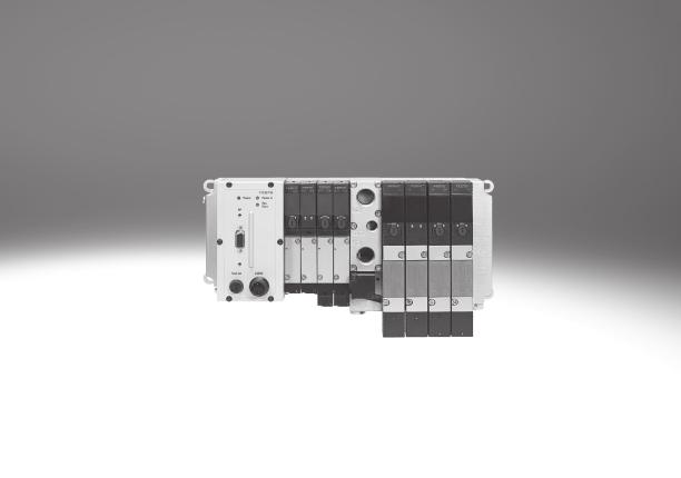
3 Key features Modular electrical peripherals for valve terminal type 03/04 Modular electrical peripherals provide the required control technology for type 03 (MIDI/MAXI) valve terminals. Together these components form the most comprehensive system range in intelligent pneumatics and also offer the advantage of a sturdy metal design. As well as incorporating protection class IP65, the system also provides benefits through the sturdy design of its modules and connections. Individual modules are enclosed in metal housings with push-in fittings, and are made primarily of steel. The connections between the modules are protected by special seals and each connection point is secured using 3 robust M4x14 DIN 912 screws. The main industrial fieldbuses are used for networking and control. Directly integrated programmable controllers (PLC) with fieldbus interface from Festo can also be used for actuation. The module also offers various actuation and connection options for machine control. Ongoing further development and a worldwide service and consultation network round off the performance spectrum for this system. -H- Note Use the menu-driven online configurator for modular electrical peripherals type 03/04 and valve terminal in the electronic catalogue on Type 03 with fieldbus connection Ordering Modular electrical peripherals type 03/04 and valve terminal are fully assembled according to your order specifications and individually tested. The finished valve terminal consists of the electrical peripherals including the required actuator and the selected components of the MIDI/MAXI or ISO modules. Modular electrical peripherals type 03/04 with valve terminal are ordered using two separate order codes. One order code defines the modular electrical peripherals type 03/04, while the other specifies the pneumatic components of the valve terminal. Modular electrical peripherals type 03/04 can naturally also be configured without a valve terminal as a remote I/O and can be used on a fieldbus or with an integrated controller. For this order, you only require the order code for the electrical peripherals. The order lists for the modular electrical peripherals type 03/04 can be found in this chapter. For information on how to order the pneumatic components see: Internet: midi/maxi 2013/07 Subject to change Internet: 3
4 Key features General Performance characteristics Control block, fieldbusconnection, multi-pin connection Optimising and extending applications: Modules for installation-saving connection using sturdy Sub-D plugs in IP65 Low-cost connections to input/ output stations and control units Extensions and supplements can be added at any time Easy mounting: On H-rail On mounting surface With covers in welding environments Simple servicing and maintenance: LED display Manual override Clip-on inscription labels Input/output modules Flexible for control systems thanks to an extensive range of connection nodes: Multi-pin connection Fieldbus connection Proportional pneumatics: To detect, control/regulate universal variables (4 20 ma or 0 10 V DC) within the process locally to IP65 Electrical digital inputs/outputs: Max. 12 modules in conjunction with suitable nodes Inputs for 24 V DC sensors, PNP Outputs for small-load power consumers 24 V DC Types of pneumatic valve terminals supported Type 03 MIDI/MAXI valve terminals General functions of the bus nodes and control blocks A bus node or control block is at the heart of the modular electrical peripheral system. They manage the communication connection to higher-order controllers and master interfaces and a PLC program with a full range of additional functions is executed directly in the control block. The power supply for the I/O modules and the sensors connected to them is provided by means of the bus node or control block, as is the load supply for the solenoid coils and the electronic outputs. System monitoring and diagnosis are further important functions of the bus node or control block. The diagnostics are composed of three elements: Device-specific information displayed directly on the bus node or control block by means of LEDs. Device-specific status bits that are transferred to the control program via the network. Protocol-specific diagnoses. The bus nodes or control blocks collect the most important diagnostic data in the status bits and transfer it to the higher-order controller as logical inputs. Suitable further processing functions in the control program provide helpful information on the status of the power supply, short circuits and overload (with some of this information relating to specific modules or channels). Further protocol and node-specific diagnostic services are described in conjunction with the individual I/O modules, bus nodes and control blocks. 4 Internet: Subject to change 2013/07
5 Key features Electrical components Supply voltage Theentirepowersupplyforthesystem and the sensors and actuators connected to it is provided via an M18 mains plug. The power supply for the electrical peripherals type 03 and 04 is split in two. Pin 1 of the mains plug provides the sensor supply for the input modules and supplies the internal electronics of the individual modules. The sensor supply is protected separately from the electronics supply in thenodebymeansofa2afuse.we recommend that pin 1 be additionally protected against short circuit/overload by means of a 3.15 A external fuse. Pin 2 of the mains plug provides the load supply for solenoid coil actuation and the electrical 24 V DC outputs. The load supply must be externally protected against short circuit and overload by means of a 10 A strong fuse. The load voltage of the valves and electrical outputs can be disconnected separately. The common 0 V line is connected to pin 3. Pin 4 serves as an earth terminal. Example of circuit Connectionofacommon24VDC power supply and the protective earth (type 03 used in the example) Electrical outputs (externally fused) 2 Valves 3 Voltage supply connection for node type 03 4 Potential equalisation 5 Load voltage, can be disconnected separately 6 Power supply unit (e.g. central voltage supply) 7 24 V DC electronics 8 Electrical inputs/sensors Pin allocation V DC supply for electronics and inputs 2 24VDCloadsupplyforvalves 3 0V 4 Earth terminal 2013/07 Subject to change Internet: 5
6 Key features Diagnosis General system diagnosis Diagnostic information Description Function Short circuit/overload at output Output has short-circuited or become overloaded Monitors the electrical outputs of the output modules V Valves < 21.6 V DC Load voltage at pin 2 (valves and outputs) of the operating Monitors the tolerance of the load voltage for valves and voltage connection < 21.6 V DC electrical outputs V Outputs < 10 V DC V Sensor < 10 V DC Load voltage at pin 2 (valves and outputs) of the operating voltage connection < 10 V DC Operating voltage at pin 1 (electronics and inputs) of the operating voltage connection < 10 V DC Monitors the load voltage for valves and electrical outputs (novoltage,e.g.emergency-stop) Monitors the operating voltage for inputs (sensors). Indicates whether an internal fuse has tripped, either the fuse in the node or at least an electronic fuse in the input module 1). 1) An electronic fuse for input modules has been available since February General guidelines on I/O addressing A maximum of 12 electrical modules can be assembled. Note, however, that some modules occupy 2 or even 3 module positions, in which case the maximum number of modules that can be assembled is reduced. All 12 module positions can generally be used as inputs or outputs, however there are various fieldbus-specific restrictions that are documented in the node description. The number and type of inputs/outputs, and hence input/output modules, supported by the network also depends on the fieldbus node used. The number of solenoid coils is restrictedto26andisincludedinthe address space of the digital outputs. Each sub-base for single solenoid valves occupies 2 outputs, and each sub-base for double solenoid valves occupies 4 outputs. Within the output addresses, the valve solenoids are counted in ascending order from left to right starting from the node. In the case of double solenoid valves, coil 14 comes before coil 12 in the counting mode. Theaddressspaceofthevalvesisalways rounded up to a value divisible by 4. The solenoid coils are followed by the general outputs in the address space. The individual outputs in the output modules are listed in the address space in ascending order, from top to bottom and the modules are listed from right to left starting from the node (see diagram). ValveNo Test method for activation of the solenoid coils The fieldbus nodes generally contain two different test sequences that activate the solenoid coils independently of any fieldbus combination or higherorder controller so that the function of the assembled valves can be verified. The solenoid coils will be activated in parallel or serial mode depending on the test sequence selected, with each coil individually activated with a constant switching frequency in a predefined order. 6 Internet: Subject to change 2013/07
7 Peripherals overview Fieldbus systems Fieldbus systems, programmableterminalgroups Fieldbus variations: Of the more than 20 different fieldbus systems (protocols) available in the market, some have emerged as the most important variants. Festo supports these by means of various fieldbus nodes (FBxx) on its valve terminals. Fieldbus systems require a powerful, central PLC and a master interface adapted to that particular fieldbus. Fieldbus systems are generally used when several devices with many inputs/outputs, complex functions or high communication levels must be controlled. In this case, the advantages of simple cabling, easy diagnosis and maintenance outweigh the extra outlay for a fieldbus master interface and the necessary know-how. INTERBUS, INTERBUS-FOC: An open fieldbus standard, originally developed by Phoenix Contact and now in worldwide use. Important installation accessories such as bus plugs must be obtained from Phoenix oritspartners(festofb6).festofb21 is required for INTERBUS-FOC, the Interbus variant Rugged Line with fibre optic cable. PROFIBUS DP: An open fieldbus standard, originally developed by Siemens and in worldwide use (Festo FB13 for 12 MBd). 2013/07 Subject to change Internet: 7
8 Peripherals overview Bus nodes Equipping with bus node Input/output module 2 Analogue stage 3 Output module 4 Input module 5 Bus node 6 Connection side for pneumatics Modular electrical peripherals for type 03/04 can be equipped with bus node. In addition to controlling the valves and electrical outputs, corresponding sensor feedback can be recorded at the electrical peripherals and transmitted via the fieldbus to the control cabinet. The following applies to bus nodes: Max. 26 valve solenoid coils Number of inputs dependent on fieldbus type Number of electrical outputs dependent on fieldbus type and number of pneumatic valves Status bits for program controlled diagnosis occupy 4 input bits Undervoltage of valves Undervoltage of sensors Short circuit at outputs I/O allocation, self-configuration Subsequent addition of input or output modules moves the addressing (I/O allocation) forwards I/O allocation of inputs and outputs independent from each other 4-fold and 8-fold input modules connect to the next Half-Byte (nibble) Electrical outputs connect to the next Half-Byte (nibble) on the valves. Counting mode: Valves from left to right, then from the next Nibble electrical outputs from right to left Max. 12 modules are permitted on the left (electrical) side 8 Internet: Subject to change 2013/07
9 Peripherals overview Bus nodes Fieldbus node View Code Type Fieldbus protocol Suitable for Page/Internet I/O Analogue FB6 IFB6-03 INTERBUS 11 60/64 F13 IFB13-03 PROFIBUS DP, 12 MBd 15 92/74 Overview Address space for bus nodes Bus protocol Max. total Max. digital Max. analogue Inputs Outputs Inputs Outputs Inputs Outputs IFB6-03 INTERBUS 60 bit 64 bit 60 DI 60 DO 8AI 8AO IFB13-03 PROFIBUS DP 92 bit 74 bit 92 DI 74 DO 12 AI/AO DI = Digital inputs (1 bit) DO = Digital outputs (1 bit) AI = Analogue inputs (16 bit) AO = Analogue outputs (16 bit) 2013/07 Subject to change Internet: 9
10 Peripherals overview Electronics modules with bus node combinations Electronics modules Type Bus node Page/Internet IFB6-03 IFB13-03 Input modules VIGE-03-FB-8-5POL Input module for standard inputs PNP, 8-fold, 5-pin VIGE-03-FB-8,1-5POL Input module for high-speed inputs (1 ms) PNP, 8-fold, 5-pin VIGE-03-FB-8-5POL-S Input module for standard inputs PNP, 8-fold, 5-pin, with separate fuse VIGE-03-FB-4-5POL Input module for standard inputs PNP, 4-fold, 5-pin VIGE-03-FB-16-SUBD-S Input module with Sub-D plug PNP, 16-fold, 2x 15-pin socket 23 Output modules VIGA-03-FB-4-5POL Output module for standard outputs PNP, 4-fold, 5-pin 26 Input/output modules VIEA-03-FB-12E-8A-SUBD Input/output module PNP, 12I/8O, Sub-D 28 Analogue stage VIAU-03-FB-U Analogue stage 3I/1O, 0 10 V DC VIAU-03-FB-I Analogue stage 3I/1O, 4 20 ma Internet: Subject to change 2013/07


11 Technical data Bus node IFB6-03 This bus node handles communication between the modular electrical peripherals and a higher-order master. For the modular electrical peripherals, this module provides the separate electrical system supply for the electronics modules and sensor supply, and the load current of the electrical outputs and valves. Application Bus connection The bus connection is established via two 9-pin M23 connections with a typical INTERBUS pin allocation. The plug and socket are labelled with Remote IN and Remote OUT in accordance with the definition for the INTER- BUS remote bus. Bothbuscablesarealwaysroutedto the bus node and looped through in accordance with the ring structure of the INTERBUS. Implementation The IFB6-03 supports the digital input and output modules and the solenoid coils. It also supports analogue modules. It can service a total of 64 digital outputs, of which max. 26 can include solenoid coils, and 60 digital inputs. The FB6 supports max. 8 analogue input channels and 8 analogue output channels. The analogue channels are operated in multiplex mode and occupy 16 process data bits. The number of possible digital inputs and outputs is reduced by 16 bits when analogue modules are used. -H- Note Please observe the general guidelines on I/O addressing when assigning the outputs. 2013/07 Subject to change Internet: 11
12 Technical data Bus node IFB6-03 General technical data Type IFB6-03 Combination with analogue modules Yes Baud rates [kbps] 500 ID code 1, 2 or 3 depending on expansion No. of process data bits 16, 32, 48 or 64 depending on expansion PCP channel No Configuration support Icon file for CMD software Station description file with CMD software Max. no. of solenoid coils 26 Max. no. of outputs incl. solenoid coils 64 Max. no. of inputs 60 LED diagnostic displays UL Operating voltage of internal electronics UI Operating voltage of INTERBUS interface RC Remotebus check BA Bus active RD Remotebus disable Device-specific diagnostics transmitted to the controller Short circuit/overload, outputs Undervoltage of valves Undervoltage of outputs Undervoltage of sensor supply Error during analogue processing Operating voltage Nominal value [V DC] 24 polarity-safe Permissible range [V DC] Power failure buffering [ms] 20 Current consumption [ma] total current consumption of inputs, internal Protection class to EN IP65 Temperaturerange Operation [ C] Storage [ C] Materials Housing Die-cast aluminium Cover Polyamide Dimensions (HxWxD) [mm] 132 x 85 x 125 Grid dimension [mm] 72 Weight [g] Internet: Subject to change 2013/07
13 Technical data Bus node IFB6-03 Connection and display components The following connection and display components can be found on the bus node cover: Power supply indicator 2 Fieldbus status indicator 3 INTERBUS interface 4 Fuse for operating voltage of inputs 5 Operating voltage connection Pin allocation for the INTERBUS interface, non-floating installation remote bus Terminal allocation Pin 1) Signal Designation Incoming Plug view 1 DO Data out 2 /DO Data out inverse 3 DI Data in 4 /DI Data in inverse 5 Ground Reference conductor 6 FE Functional earthing V DC Installation remote bus supply 8 +0 V Installation remote bus supply Sleeve Screen Screening Outgoing Socket view 1 DO Data out 2 /DO Data out inverse 3 DI Data in 4 /DI Data in inverse 5 Ground Reference conductor 6 FE Functional earthing Installation remote bus V DC Installation remote bus supply 8 +0 V Installation remote bus supply 9 RBST Establish bridge to pin 5 Sleeve Screen Screening 1) Pins not listed here must not be connected. 2013/07 Subject to change Internet: 13
14 Accessories Bus node IFB6-03 Ordering data Designation Part No. Type Bus node INTERBUS IFB6-03 -U- Power supply Plug socket, straight, M18x1, 4-pin for 1.5 mm NTSD-GD-9 for 2.5 mm NTSD-GD-13,5 Plug socket, angled, M18x1, 4-pin for 1.5 mm NTSD-WD-9 for 2.5 mm NTSD-WD-11 User documentation User documentation Bus node IFB6-03 German P.BE-VIFB6-03-DE -U- English P.BE-VIFB6-03-EN -U- French P.BE-VIFB6-03-FR -U- Spanish P.BE-VIFB6-03-ES -U- Italian P.BE-VIFB6-03-IT -U- Swedish P.BE-VIFB6-03-SV -U- 14 Internet: Subject to change 2013/07
15 Technical data Bus node IFB13-03 Bus node for handling communication between the modular electrical peripherals and a higher-order master via PROFIBUS DP. For the modular electrical peripherals, this module provides the separate electrical system supply for the electronics modules and sensor supply, and the load current of the electrical outputs and valves. The status of the voltage supplies and the bus communication is indicated via the LEDs Power, Power Valves and Bus Error. Application Bus connection The bus connection is established via a9-pinsub-dsocketwithatypical PROFIBUS allocation (to EN ). The bus connector plug (with protection class IP65 from Festo or IP20 from other manufacturers) facilitates the connection of an incoming and an outgoing bus cable. An active bus terminal can be connected using the integrated DIL switch. The Sub-D interface is designed for the control of network components with a fibre optic cable connection. -H- Note A Reverse Key connection can be established via a 2x M12 adapter plug (B-coded). Implementation The IFB13-03 supports digital input and output modules and solenoid coils. Analogue modules can also be used. 74 digital outputs in total, of which max. 26 solenoid coils. Max. 92digital inputs for recording sensor signals. The bus node supports max. 12 analogue input/output channels. Analogue modules occupy a discrete address space, separate from the digital inputs and outputs. -H- Note Please observe the general guidelines on I/O addressing when assigning the outputs. 2013/07 Subject to change Internet: 15
16 Technical data Bus node IFB13-03 General technical data Type IFB13-03 Combination with analogue modules Baud rates Addressing range Product family Ident. number Type of communication Configuration support Yes Automatic detection 9.6kBaud 12MBaud Set using 2 rotary switches and a DIL switch : Valves 0xFB13 Cyclic communication GSD file and bitmaps Max. no. of solenoid coils 26 Max. no. of outputs and solenoid coils 74 Max. no. of inputs 92 Max. no. of analogue channels 12 input/output channels LED diagnostic displays Power Operating voltage of electronics Power V Operating voltage of valves and outputs Bus Error Communication error Device-specific diagnostics via PROFIBUS DP Short circuit/overload, outputs (channel diagnostics) Undervoltage of valves Undervoltage of outputs Undervoltage of sensor supply Error during analogue processing Additional functions Status/diagnosticbitsintheprocessimageoftheinputs Test routine for checking the valves and outputs without bus communication Indication of the valve terminal configuration via Power V and Bus Error LEDs Operating voltage Nominal value [V DC] 24 polarity-safe Permissible range [V DC] Power failure buffering [ms] 20 Current consumption [ma] total current consumption of inputs, internal Protection class to EN IP65 Temperaturerange Operation [ C] Storage/transport [ C] Materials Housing Die-cast aluminium Cover Polyamide Dimensions (HxWxD) [mm] 132 x 85 x 125 Grid dimension [mm] 72 Weight [g] Internet: Subject to change 2013/07
17 Technical data Bus node IFB13-03 Connection and display components The following connection and display components can be found on the bus node cover: Green LED / Power 2 Red LED / Bus 3 Operating voltage connection 4 Fuse for operating voltage of inputs 5 Plug for fieldbus cable Pin allocation for PROFIBUS DP interface Terminal allocation Pin Signal Designation Plug, Sub-D Viewed from the socket side Socket 1 n.c. Not connected 2 n.c. Not connected 3 RxD/TxD-P Received/transmitted data P 4 CNTR-P 1) Repeater control signal 5 DGND Data reference potential (M5V) 6 VP Supply voltage (P5V) 7 n.c. Not connected 8 RxD/TxD-N Received/transmitted data N 9 n.c. Not connected Housing Screen Connection to housing Bus connection M12 adapter plug (B-coded) Plug and socket Plug 1 n.c. Not connected 2 RxD/TxD-N Received/transmitted data N 3 n.c. Not connected 4 RxD/TxD-P Received/transmitted data P 5and M12 Screen Connection to FE Socket 1 VP Supply voltage (P5V) 2 RxD/TxD-N Received/transmitted data N 3 DGND Data reference potential (M5V) 4 RxD/TxD-P Received/transmitted data P 5and M12 Screen Connection to FE 1) The repeater control signal CNTR-P is realised as a TTL signal. 2013/07 Subject to change Internet: 17
18 Accessories Bus node IFB13-03 Ordering data Designation Part No. Type Bus node PROFIBUS IFB U- Power supply Plug socket, straight, M18x1, 4 pin for 1.5 mm NTSD-GD-9 for 2.5 mm NTSD-GD-13,5 Plug socket, angled, M18x1, 4 pin for 1.5 mm NTSD-WD-9 for 2.5 mm NTSD-WD-11 Fieldbus connection Plug, Sub-D FBS-SUB-9-GS-DP-B Bus connection, 2x M12 adapter plug (B-coded) FBA-2-M12-5POL-RK SocketM12x1, 5-pin, straight PlugM12x1, 5-pin, straight for self-assembly of a connecting cable for FBA-2-M12-5POL-RK for self-assembly of a connecting cable for FBA-2-M12-5POL-RK NECU-M-B12G5-C2-PB NECU-M-S-B12G5-C2-PB User documentation User documentation Bus node IFB13-03 German P.BE-VIFB13-03-DE -U- English P.BE-VIFB13-03-EN -U- French P.BE-VIFB13-03-FR -U- Spanish P.BE-VIFB13-03-ES -U- Italian P.BE-VIFB13-03-IT -U- Swedish P.BE-VIFB13-03-SV -U- 18 Internet: Subject to change 2013/07

19 Technical data Input module, digital, 4-/8-fold Function Digital input modules facilitate the connection of proximity sensors or other 24 V DC sensors (inductive, capacitive, etc.). Plugs with double allocation are separated using a DUO plug or DUO cable. These modules cannot be operated on the multi-pin node with inputs. Applications Input modules for 24 V DC sensor signals M12 plug, single allocation connection technology in 4-fold modules, double allocation connection technology in 8-fold modules M12 plug, 5-pin The input statuses are indicated for each input signal at an allocated LED 24 V DC supply provided for all connected sensors Module width: 36 mm General technical data Type VIGE-03-FB-8-5POL VIGE-03-FB-4-5POL VIGE-03-FB-8,1-5POL Inputtype Standard inputs, PNP Inputplugwith single High-speed inputs, PNP allocation, PNP No. of inputs No. of occupied module positions 1 Sensor connection type 4xM12, 5-pin, socket with double allocation 4xM12, 5-pin, socket with single allocation Max. power supply per channel [A] 2 Max. sensor supply per module [A] 2 Fuse protection for sensor supply Central fuse 2 A, in system supply Currentconsumptionofmodule [ma] Typical 12 Supply voltage of sensors [V DC] 24 ±25%, coming from busnode Switchinglevel Signal 0 [VDC] 5DC Signal 1 [VDC] 10DC Input delay [ms] Switching logic PNP (for input signals with positive logic) Input characteristic curve To IEC Protection classto EN IP65 (when fully plugged-in or fitted with protective cover) Temperaturerange Operation [ C] Storage [ C] Material Die-cast aluminium Dimensions [mm] 132 x 36 x 70 Grid dimension [mm] 36 Weight [g] 360 4xM12, 5-pin, socket with double allocation 2013/07 Subject to change Internet: 19
20 Technical data Input module, digital, 4-/8-fold General technical data Type VIGE-03-FB-8-5POL-S Input type With separate fuse, PNP No. of inputs 8 No. of occupied module positions 1 Sensor connection type 4xM12, 5-pin, socket with double allocation Max. power supply per channel [A] 2 Max. sensor supply per module [A] 0.5 Fuse protection for sensor supply Internal electrical fuse Currentconsumptionofmodule [ma] Typical 12 Supply voltage of sensors [V DC] 24 ±25%, coming from busnode Switchinglevel Signal 0 [VDC] 6 Signal 1 [VDC] 8.6 Input delay [ms] 3 Switching logic PNP (for input signals with positive logic) Input characteristic curve To IEC Protection classto EN IP65 (when fully plugged-in or fitted with protective cover) Temperaturerange Operation [ C] Storage [ C] Material Die-cast aluminium Dimensions [mm] 132 x 36 x 70 Grid dimension [mm] 36 Weight [g] Internet: Subject to change 2013/07
21 Technical data Input module, digital, 4-/8-fold Pin allocation Terminal allocation 4-fold 8-fold Pin Signal LED Pin Signal LED 5-pin input modules V V 0 2 n.c. 2 Ix+1 3 0V 3 0V 1 4 Ix 4 Ix 5 Earth terminal 5 Earth terminal V V 2 2 n.c. 2 Ix+3 3 0V 3 0V 3 4 Ix+1 4 Ix+2 5 Earth terminal 5 Earth terminal V V 4 2 n.c. 2 Ix+5 3 0V 3 0V 5 4 Ix+2 4 Ix+4 5 Earth terminal 5 Earth terminal V V 6 2 n.c. 2 Ix+7 3 0V 3 0V 7 4 Ix+3 4 Ix+6 5 Earth terminal 5 Earth terminal Ix Input x 2013/07 Subject to change Internet: 21
22 Accessories Input module, digital, 4-/8-fold Ordering data Designation Part No. Type Input module, digital 8 digital inputs, positive logic (PNP), standard inputs VIGE-03-FB-8-5POL -U- 4 digital inputs, positive logic (PNP), input plug with single allocation VIGE-03-FB-4-5POL -U- 8 digital inputs, positive logic (PNP), high-speed inputs VIGE-03-FB-8,1-5POL -U- 8 digital inputs, positive logic (PNP), with separate fuse VIGE-03-FB-8-5POL-S -U- Sensor plug Plug, straight socket, M12 5-pin, PG SEA-M12-5GS-PG7 4-pin, PG SEA-GS-7 4-pin, 2.5 mm 2 OD SEA-4GS-7-2,5 Plug for 2 sensor cables, M12, PG11 4-pin SEA-GS-11-DUO 5-pin SEA-5GS-11-DUO DUO cable DUO cable 2x straight socket KM12-DUO-M8-GDGD 2x straight/angled socket KM12-DUO-M8-GDWD 2x angled socket KM12-DUO-M8-WDWD 22 Internet: Subject to change 2013/07
23 Technical data Input module, digital, 16-fold Function Sensor signals in groups of up to 8 or 12 are recorded by multi-pin distributors and forwarded to the module via a multi-pin cable. Applications Input modules for 24 V DC sensor signals 2 connector plugs, Sub-D 15-pin socket Ready for installation for multi-pin distributors with up to 8 or 12 inputs Allocation of the plug variables 8 inputs on top and 8 inputs on bottom 12 inputs on top and 4 inputs on bottom The input statuses are indicated for each input signal at an assigned LED 24 V DC voltage supplied separately for both plugs, with separate electronic fuse Module width: 36 mm General technical data Type VIGE-03-FB-16-SUBD-S No. of inputs 16 No. of occupied module positions 2 Sensor connection type 2x Sub-D, 15-pin socket Max. sensor supply per connection [A] 0.5 Max. sensor supply per module [A] 1 Fuse protection for sensor supply Separate electronic fuse for each connection Current consumption of module [ma] 12 Supply voltage of sensors [V DC] 24 ±25%, coming from busnode Switchinglevel Signal 0 [VDC] 6 Signal 1 [VDC] 8.6 Input delay [ms] 3 Switching logic PNP (for input signals with positive logic) Input characteristic curve To IEC Protection classto EN IP65 (when fully plugged-in or fitted with protective cover) Temperaturerange Operation [ C] Storage [ C] Material Die-cast aluminium Dimensions (HxWxD) [mm] 132 x 36 x 56 Grid dimension [mm] 36 Weight [g] /07 Subject to change Internet: 23
24 Technical data Input module, digital, 16-fold Pin allocation Terminal allocation Pin Signal 1 1 ae ae 1 Ix 2 Ix+1 3 Ix+2 4 Ix+3 5 Ix+4 6 Ix+5 7 Ix+6 8 Ix+7 9 Ix+8 1) 10 Ix+9 1) 11 Ix+10 1) 12 Ix+11 1) V DC sensor supply 14 0V 15 PE housing 1 Ix+8 1) 2 Ix+9 1) 3 Ix+10 1) 4 Ix+11 1) 5 Ix+12 6 Ix+13 7 Ix+14 8 Ix+15 9 Free 10 Free 11 Free 12 Free V DC sensor supply 14 0V 15 PE housing Ix Input x 1) Two sets of inputs signals, connect to either of the two plugs. 24 Internet: Subject to change 2013/07
25 Accessories Input module, digital, 16-fold Ordering data Designation Part No. Type Input module, digital 16 digital inputs, positive logic (PNP), 2x Sub-D, 15-pin socket VIGE-03-FB-16-SUBD-S -U- Multi-pin distributors Technical data pin plug Sub-D / 8x 3-pin M8 sockets 8I/Os MPV-E/A08-M8 15-pin plug Sub-D / 12x 3-pin M8 sockets 12 I/Os MPV-E/A12-M8 15-pin connecting cable / 8x 5-pin M12 sockets 8I/Os MPV-E/A08-M12 Cables and plugs Plug socket with cable, open at one end 5m KMPV-SUB-D m KMPV-SUB-D Plug socket Sub-D, plug SD-SUB-D-ST /07 Subject to change Internet: 25
26 Modular electri peripherals, for type 03/04 Technical data Output module, digital Function The electrical outputs control actuators such as individual valves, hydraulic valves, heating controllers and many more. -H- Note Valves with M12 central plug, optimum control. Applications Output module with 4 outputs 24 V DC M12 connection technology, with 5-pin sockets LED display of the switching status per channel Short circuit and overload detection per output Separate malfunction display for each channel by means of red LED Diagnostic message about system status to controller General technical data Type VIGA-03-FB-4-5POL Output type Standard outputs, PNP No. of outputs 4 No. of occupied module positions 1 Output connection type 4xM12, 5-pin, socket with double allocation Max. outputcurrent per channel [A] 0.5 per module [A] 2.0 Operating voltage [V DC] 24 ±25% Load voltage connection [V DC] 24 ±10% Parallel connection possible Yes, within the module only Fuse protection for output line Electronic fuse per channel 0.5 A Current consumption of module [ma] 9 Overload/short circuit protection Per channel Switching logic To IEC Protection classto EN IP65 (when fully plugged-in or fitted with protective cover) Temperaturerange Operation [ C] Storage [ C] Material Die-cast aluminium Dimensions (HxWxD) [mm] 132 x 36 x 69 Grid dimension [mm] 36 Weight [g] Internet: Subject to change 2013/07
27 Accessories Output module, digital Pin allocation Standard Terminal allocation LED Pin Signal n.c. 2 Ox+1 3 0V 4 Ox 5 Earth terminal 1 1 n.c. 2 n.c. 3 0V 4 Ox+1 5 Earth terminal 2 1 n.c. 2 Ox+3 3 0V 4 Ox+2 5 Earth terminal 3 1 n.c. 2 n.c. 3 0V 4 Ox+3 5 Earth terminal 1 Internal connection in module Ox Output x Ordering data Designation Part No. Type Output module, digital 4 digital outputs, positive logic (PNP), standard outputs VIGA-03-FB-4-5POL -U- Sensor plug Plug,straightsocket,M12 5-pin, Pg SEA-M12-5GS-PG7 Plug for 2 sensor cables, M12, PG11 5-pin SEA-5GS-11-DUO DUO cable DUO cable 2x straight socket KM12-DUO-M8-GDGD 2x straight/angled socket KM12-DUO-M8-GDWD 2x angled socket KM12-DUO-M8-WDWD 2013/07 Subject to change Internet: 27
28 Technical data Input/output module Function Digital input modules facilitate the connection of proximity sensors or other 24 V DC sensors (inductive, capacitive, etc.). The electrical outputs control actuators such as individual valves, lamps and a host of other devices. The I/O module occupies 3 module positions. Its electrical isolation makes it suitable as a coupling connection to external circuits. Applications The I/O module combines 12 inputs and 8 outputs in one module with a width of 72 mm. The connection is established via a pre-assembled 25-pin Sub-D plug with multi-pin cable. 24 V DC internal supply to the sensor connections. The switching status displays for the inputs/outputs are shown on assigned LEDs. 4 outputs are combined into a group and supplied externally with 24 V DC. The inputs and outputs are electrically isolated from the node. General technical data Type VIEA-03-FB-12E-8A-SUBD Number Inputs 12 Outputs 8 No. of occupied module positions 3 Sensor connection and output type 25-pin multi-pin cable and Sub-D plug connector Max. power supply per channel [A] 2 Max. sensor supply per module [A] 2 Fuse protection for sensor supply Central fuse 2 A, in system supply Current consumption of module Typically 8 ma (inputs) 5 ma (outputs) per group of four Capacity per digital output [A] 0.5 internal electronic fuse Supply voltage of sensors [V DC] 24 ±25%, coming from busnode Switching level Signal 0 [V DC] 5 Signal 1 [V DC] 11 Input delay [ms] 5 Switching logic PNP (for input signals with positive logic) Input characteristic curve To IEC Protection classto EN IP65 (when fully plugged-in or fitted with protective cover) Temperaturerange Operation [ C] Storage [ C] Material Die-cast aluminium Dimensions (HxWxD) [mm] 132 x 78 x 78 Grid dimension [mm] 72 Weight [g] Internet: Subject to change 2013/07
29 Accessories Input/output module Pin allocation Pin Signal Core colour of data cable KEA-1-25P- 1 Ix white 2 Ix+1 green 3 Ix+2 yellow 4 Ix+3 grey 5 Ix+4 pink 6 Ix+5 blue 7 Ix+6 red 8 Ix+7 magenta 9 Ix+8 grey-pink 10 Ix+9 red-blue 11 Ix+10 white-green 12 Ix+11 brown-green 13 0Vofinputs white-yellow 14 Ox yellow-brown 15 Ox+1 white-grey 16 Ox+2 grey-brown 17 Ox+3 white-pink 18 Ox+4 pink-brown 19 Ox+5 white-blue 20 Ox+6 brown-blue 21 Ox+7 white-red V DC (for the outputs Ox Ox+3) brown-red V DC (for the outputs Ox+4 Ox+7) white-black 24 0 V (for the outputs Ox Ox+3) brown 25 0V(fortheoutputsOx+4 Ox+7) black Ix Ox Input x Output x Ordering data Designation Part No. Type Input/output module, digital 12 digital inputs, 8 digital outputs VIEA-03-FB-12E-8A-SUBD -U- Cables and plugs Connecting cable 5m KEA-1-25P-5 10 m KEA-1-25P-10 xlength KEA-1-25P-X Plug socket Sub-D, socket SD-SUB-D-BU /07 Subject to change Internet: 29

30 Technical data Analogue stage Function Analogue signals, as well as digital inputs and outputs, are required in many areas of automation. Special analogue stages are provided for these tasks which are capable of processing both analogue input signals, e.g. setpoint specifications and feedback on actual values (temperature, pressure, flow rate, filllevel, etc.), as well as analogue outputs for controlling actuators. The analogue stages are specially prepared for the connection of proportional valves 1). Applications 6-pin push-in connectors to DIN Diagnostic LED to indicate readiness for service and overload Voltage supplied for all connected sensors Two analogue stages are available for different fields of application: VIAU-03-FB-I, universal module for current signals 3 analogue inputs (4 20 ma) 1 analogue output (4 20 ma) VIAU-03-FB-U, universal module for voltage signals 3 analogue inputs (0 10 V) 1 analogue output (0 10 V) VIAU-03-FB- 1) Not suited for MPPES General technical data Type VIAU-03-FB-I 1) VIAU-03-FB-U 1) Number Inputs 3 3 Outputs 1 1 Sensor connection type 3x 6-pin socket, DIN Max. sensor supply per module [A] Fuse protection for sensor supply Central fuse 2 A, in system supply Current consumption of module [ma] 64 Supply voltage of sensors [V DC] 24 ±25%, coming from busnode Actuator supply voltage [V DC] 24 ±10%, external Actuator supply, average continuous loading capability [A] Max. 1 Analoguecurrentinputs Signal range 4 20mA 0 10VDC Resolution [bit] No. of units Absolute precision [%] Input resistance [kω] Max. permissible input current [ma] 65 Input voltage [V DC] 30 Input signal cut-off frequency [Hz] 116 Linearity Differential non-linearity 2LSB Integral non-linearity 3LSB 1) Not suited for MPPES 30 Internet: Subject to change 2013/07
31 Technical data Analogue stage General technical data Type VIAU-03-FB-I 1) VIAU-03-FB-U 1) Analoguecurrentinputs/outputs Signal range 4 20mA 0 10VDC Resolution [bit] 12 No. of units Absolute precision [%] Load resistance (load) [kω] Linearity Differential non-linearity 2LSB Integral non-linearity 4LSB Protection classto EN IP65 (when fully plugged-in or fitted with protective cover) Temperaturerange Operation [ C] Storage [ C] Material Die-cast aluminium Dimensions (HxWxD) [mm] 132 x 42 x 70 Grid dimension [mm] 36 Weight [g] 360 1) Not suited for MPPES 2013/07 Subject to change Internet: 31
32 Technical data Analogue stage Pin allocation Terminal allocation Signal Signal designation Analogue stage VIAU-03-FB-I (current signals) II0 II0+ 0V II1 II1+ n.c. n.c. 24 V Sen n.c. n.c. 24 V Sen IIx+ Positive current, input signal IIx Negative current, input signal OI0+ Positive current, output signal OGND Current output signal 24 V Sen 24 V DC sensor supply voltage 24 V p 24 V DC actuator supply voltage 0V 0 V actuator/sensor supply voltage Housing Cable screening connection 0V OI0+ II2 II2+ OGND 24 V P 0V Analogue stage VIAU-03-FB-U (voltage signals) n.c. n.c. 0V n.c. n.c. IU0+ IU0 24 V Sen IU1+ IU1 24 V Sen IUx+ Positive voltage, input signal IUx Negative voltage, input signal OU0+ Positive voltage, output signal OGND Voltage output signal 24 V Sen 24 V DC sensor supply voltage 24 V p 24 V DC actuator supply voltage 0V 0 V actuator/sensor supply voltage Housing Cable screening connection 0V OU0+ IU2 IU2+ OGND 24 V P 0V 32 Internet: Subject to change 2013/07
33 Accessories Analogue stage Ordering data Designation Part No. Type Input module, analogue 3 analogue inputs and 1 analogue output, universal module for current signals VIAU-03-FB-I -U- 3 analogue inputs and 1 analogue output, universal module for voltage signals VIAU-03-FB-U -U- Connecting cables Connecting cable for Festo proportional pressure regulator, plug/socket pre-assembled at both ends Connecting cable for Festo proportional directional control valve, plug/socket pre-assembled at both ends Connecting cable for other signal modules, open cable end 5m KVIA-MPPE-5 10 m KVIA-MPPE-10 5m KVIA-MPYE-5 10 m KVIA-MPYE-10 5m KVIA-5 10 m KVIA-10 User documentation User documentation Analogue stage German P.BE-VIAX-03/05-DE -U- English P.BE-VIAX-03/05-EN -U- French P.BE-VIAX-03/05-FR -U- Spanish P.BE-VIAX-03/05-ES -U- Italian P.BE-VIAX-03/05-IT -U- Swedish P.BE-VIAX-03/05-SV -U- 2013/07 Subject to change Internet: 33
, collect the sensor signals directly in the machine and forward them to the input module on the 15-pin")
34 Technical data Multi-pin distributor Function MPV multi-pin distributors are suitable for the distribution of input and output signals to PNP sensors and solenoid valves via the M12/M8 plugs. The multi-pin distributors, in conjunction with the input module VIGE-03-FB-16-SUBD-S ( 23), collect the sensor signals directly in the machine and forward them to the input module on the 15-pin Sub-D sockets via a multi-pin cable. LED for signal status display Only one cable to installation location A broad range of accessories Type MPV-E/A -M8 The multi-pin distributor facilitates the connection of max. 8 or 12 input signals to 3-pin M8x1 plugs. The connecting cable KMPV-SUB- D-15-, pre-assembled at one end, with the 15-pin Sub-D socket is connected to the multi-pin distributor. The open end of the cable is fitted with the plug socket SD-SUB-D-ST15 and connected to the input module. Type MPV-E/A08-M12 Connection of max. 8 input signals to 5-pin M12 plug. The connecting cable is permanently attached to the multi-pin distributor. The open end of the cable is fitted with the plug socket SD-SUB-D-ST15 and connected to the input module. Switching status display via yellow LED. Sensor voltage display via green LED. MPV-E/A -M8 MPV-E/A08-M12 General technical data Type MPV-E/A08-M8 MPV-E/A12-M8 MPV-E/A08-M12 No. of inputs/outputs Type of mounting 2 through-holes or on H-rail 1) 3through-holes Connection M8x1, 3-pin M12x1,5-pin Permissible voltage [V DC] Current-carrying capacity [A] Max. 1 per module slot Totalcurrent:max.4 Max. 4 per module slot Totalcurrent:max.12 Protection class to EN IP65 (fully assembled) IP67 (fully assembled) Temperaturerange Operation [ C] Storage [ C] Materials Housing Polyamide Polyurethane Sockets Brass, gold plated Galvanised brass Cable Polyurethane, polyvinyl chloride Weight [g] 100 2) 120 2) 200 2) 1) With adapter CP-TS-HS-35 2) Without cable 34 Internet: Subject to change 2013/07
35 Technical data Multi-pin distributor Dimensions MPV-E/A -M8 Download CAD data 1 Multi-pin connection 2 3-pin socket, M8x1 3 Switching status display, yellow 4 Inscription label (type IBS-6x10) 1 24VDC 3 0V 4 Signal line (1 8) or (1 12) MPV-E/A08-M12 1 Connecting cable, 5 m 2 5-pin socket, M12 x 1 3 Switching status display, yellow 4 Voltage display, green 1 24VDC 2 n.c. 3 0V 4 Signal line (1 8) 5 Earth 2013/07 Subject to change Internet: 35
36 Accessories Multi-pin distributor Pin allocation MPV-E/A -M8 Cable with 15-pin Sub-D plug Pin M8 socket Core colour location MPV-E/A08-M12 Signal line pins 1 through 12 M12 socket Core colour location 1 0/4 white 1/4 white 2 1/4 brown 2/4 green 3 2/4 green 3/4 yellow 4 3/4 yellow 4/4 grey 5 4/4 grey 5/4 pink 6 5/4 pink 6/4 red 7 6/4 blue 7/4 black 8 7/4 red 8/4 magenta 9 8/4 black 24 V DC brown 10 9/4 magenta 0V blue 11 10/4 grey-pink PE green-yellow 12 11/4 red-blue V DC white-green 14 0V brown-green 15 0V white-yellow Ordering data for MPV-E/A08-M12 Designation Part No. Type Multi-pin distributors 15-pin connecting cable / 8x 5-pin M12 sockets MPV-E/A08-M12 Plugs and cables Connecting cable for sensors, M12-M m KM12-M12-GSGD-2,5 5m KM12-M12-GSGD-5 Plug socket 1) SD-SUB-D-ST15 Protective cover Cover caps (10 pieces) for unused terminals ISK-M12 1) A Sub-D plug socket is required to establish a connection between the multi-pin distributor and input module VIGE-03-FB-16-SUBD-S. 36 Internet: Subject to change 2013/07
37 Accessories Multi-pin distributor Ordering data for MPV-E/A -M8 Designation Part No. Type Multi-pin distributors 15-pin plug Sub-D / 8x 3-pin M8 sockets MPV-E/A08-M8 15-pin plug Sub-D / 12x 3-pin M8 sockets MPV-E/A12-M8 Plugs and cables Connecting cable for sensors, M8-M8 2.5 m KM8-M8-GSGD-2,5 5m KM8-M8-GSGD-5 Plug socket with cable, open at one end 1) 5m KMPV-SUB-D m KMPV-SUB-D Plug socket 1) SD-SUB-D-ST15 Protective cover Cover caps (10 pieces) for unused terminals ISK-M8 Designation Inscription labels, pack of IBS-6x10 Mounting Attachment for H-rail mounting, 2 pieces CP-TS-HS-35 1) A plug socket with cable and a Sub-D plug socket are required to establish a connection between the multi-pin distributor and input module VIGE-03-FB-16-SUBD-S. 2013/07 Subject to change Internet: 37
38 Technical data Dimensions Electrical peripherals with valve terminal type 03 with bus node/control block Download CAD data 1 Input/output module 2 Input module 3 Fieldbus/control block 4 Adapter plate MIDI/MAXI with pressure regulating valve for pilot pressure 5 End plate, right-hand (dimensions for MIDI valves in brackets) 6 Compressed-air supply plate 7 Mounting bracket for wall mounting required approx. every 200 mm 8 One-way flow control valve 9 Pressure regulating valve aj End plate, left-hand aa Swivel lever IBGH (opened out) for connection to mounting rail ab Swivel lever IBGH (opened out) for connection to mounting rail 38 Internet: Subject to change 2013/07
39 Technical data Dimensions End plates for valve terminal 03 MIDI valves MAXI valves Download CAD data 1 Silencer 2 Pressure regulating valve 3 H-rail 1 Silencer 2 Pressure regulating valve 3 H-rail 2013/07 Subject to change Internet: 39
40 Technical data Dimensions Electrical peripherals with valve terminal type 04 with bus node/control block Download CAD data Electrical channel 1 Output module 2 Fieldbus node/control block 3 Adapter plate 4 ISO valve 5 Intermediate pressure regulator plate 6 Throttle plate 7 Intermediate solenoid plate 8 Blanking plate 9 Manifold sub-base aj End plate aa Mounting hole (only with VIFB-04-D-1) Type ~B1 B2 B3 B4 B5 B6 B7 B8 B9 B10 B11 D1 D2 D3 VIFB-04-D-1-B G½ G¼ 6.6 VIFB-04-D-2-B G¾ Gy 6.6 VIFB-04-D-3-B G1 G½ 9 Type H1 H2 H3 H4 H5 L1 1) L2 L3 L4 L5 L6 L7 L8 1) L9 VIFB-04-D-1-B mx (m 1) x VIFB-04-D-2-B mx (m 1) x 59 VIFB-04-D-3-B mx (m 1) x 72 1) m = Number of valves 40 Internet: Subject to change 2013/07
41 Accessories Product range overview Connections for bus nodes and control blocks Designation Type FB6 -U- FB13 -U- FB21 -U- Fieldbus connection Plug, Sub-D FBS-SUB-9-GS-DP-B Bus connection, 2x M12 adapter plug (B-coded) FBA-2-M12-5POL-RK INTERBUS standard round plug 1) INTERBUS Rugged Line FOC plug 1) Power supply Plug socket, straight, for 1.5 mm 2 NTSD-GD-9 Plug socket, straight, for 2.5 mm 2 NTSD-GD-13,5 Plug socket, angled, for 1.5 mm 2 NTSD-WD-9 Plug socket, angled, for 2.5 mm 2 NTSD-WD-11 1) Not a Festo product, order from Phoenix Contact 4-/8-fold VIGE- Product range overview Electrical connection technology for modules Designation Type Input module Output module -U- Input/output module Plugs and sockets Plug, straight socket, M12, 4-pin, Pg7 SEA-GS-7 Plug, straight socket, M12, 4-pin, 2.5 mm 2 OD SEA-4GS-7-2,5 Plug, straight socket, M12, 5-pin, Pg7 SEA-M12-5GS-PG7 1) Plug for 2 sensor cables, M12, Pg11, 4-pin SEA-GS-11-DUO Plug for 2 sensor cables, M12, Pg11, 5-pin SEA-5GS-11-DUO 1) Plug socket Sub-D, plug SD-SUB-D-ST15 Plug socket Sub-D, socket SD-SUB-D-BU25 Cables Connecting cable, 5 m KEA-1-25P-5 Connecting cable, 10 m KEA-1-25P-10 Connecting cable, x length KEA-1-25P-X DUO cable, 2x straight socket KM12-DUO-M8-GDGD DUO cable, 2x straight/angled socket KM12-DUO-M8-GDWD DUO cable, 2x angled socket KM12-DUO-M8-WDWD Plug socket with cable, open at one end, 5 m KMPV-SUB-D-15-5 Plug socket with cable, open at one end, 10 m KMPV-SUB-D ) 5-pin cable, cannot be used with 4-pin connectors Product range overview Electrical connection technology for modules Designation Type Analogue stage VIAU- 16-fold VIGE- -U- VIGA- -U- VIEA- -U- -U- Cables Connecting cable for Festo proportional pressure regulator, 5 m KVIA-MPPE-5 Connecting cable for Festo proportional pressure regulator, 10 m KVIA-MPPE-10 Connecting cable for Festo proportional directional control valve, KVIA-MPYE-5 5m Connecting cable for Festo proportional directional control valve, KVIA-MPYE m Connecting cable for other signal modules, open cable end, 5 m KVIA-5 Connecting cable for other signal modules, open cable end, 10 m KVIA /07 Subject to change Internet: 41
Fieldbus Direct Key features
 Key features The system Extremely compact and spacesaving design Low-cost solution for the connection of a small number of valves to a fieldbus Extremely safe, protection class up to IP65 depending on
Fieldbus Direct Key features
 Fieldbus Direct Fieldbus Direct Key features The system Extremely compact and spacesaving design Low-cost solution for the connection of a small number of valves to a fieldbus Extremely safe, protection
Fieldbus Direct Extremely compact and space-saving
 Fieldbus Direct Extremely compact and space-saving The ideal fieldbus solution for confined fitting spaces. Info 201 Fieldbus Direct and valve terminals fromfesto theflexiblespacesaving system Convincingly
Measuring modules CPX-CMIX
 Key features At a glance Movement and measurement in one, as an integral component of the valve terminal CPX the modular peripheral system for decentralised automation tasks. The modular design means that
Service unit combinations MSE6, MSE series
 Key features Overview Product description The MSE6-E2M is an intelligent pneumatic service unit for optimising the use of compressed air as an energy medium in industrial automation technology. Equipped
Digital electropneumatic positioner
 Digital electropneumatic positioner Type 879 can be combined with Compact metal housing Graphic display with backlight Easy start-up Comprehensive range of additional software functions Profibus DPV1 (optional)
CPI installation system
 Key features Key features Innovative Sturdy Versatile Reliable Complete concept for decentralised machine and system structure; centralised and decentralised installation can be combined with the CPX terminal
Valve terminal type 03/05 Electronics Manual Field bus connection FB13
 Valve terminal type 03/05 Electronics Manual Field bus connection FB13 Field bus protocol: PROFIBUS DP 12 MBaud 163958 GB Only valid in agreement with the printed documentation accompanying the product!
Distributor, universal
 Distributor, universal Distributor, universal Product range overview Function Version Version Type Connection technology Protection class T-distributor Round plug M12 3-pin NEDU-L2R1-V8-M12G5-M12G5 1x
Digital electropneumatic positioner
 Digital electropneumatic positioner Type 879 can be combined with Compact metal housing Graphic display with backlight Easy start-up Comprehensive range of additional software functions Profibus DPV1 (optional)
CPI installation system
 Key features Key features Innovative Sturdy Versatile Reliable Complete concept for decentralised machine and system structure; centralised and decentralised installation can be combined with the CPX terminal
VersaMax IP Input Module
 Module is used to accept digital input signals. Module Specifications Housing dimensions (width x height x depth) Connection style Operating temperature Storage temperature Operating/storage humidity 60mm
Proximity sensors, block design
 Proximity sensors, block design Proximity sensors, block design Product range overview Measuring principle Version Type Mounting Switching element function Switching Electrical connection N/O contact N/C
CPX-Terminal. Brief description. CPX analogue I/O modules CPX-4AE CPX-2AA. English e [ ]
![CPX-Terminal. Brief description. CPX analogue I/O modules CPX-4AE CPX-2AA. English e [ ]](/thumbs/76/73034024.jpg "CPX-Terminal. Brief description. CPX analogue I/O modules CPX-4AE CPX-2AA. English e [ ]") CPX-Terminal Brief description CPX analogue I/O modules CPX-2AE CPX-4AE CPX-2AA English 8080173 2017-11e [8080175] Translation of the original instructions Documentation on the product For all available
CPX-Terminal Brief description CPX analogue I/O modules CPX-2AE CPX-4AE CPX-2AA English 8080173 2017-11e [8080175] Translation of the original instructions Documentation on the product For all available
Compact performance. Brief description. CPV valve terminal with AS-Interface type CPV..-GE- ASI-8E8A-Z M8. English e [ ]
![Compact performance. Brief description. CPV valve terminal with AS-Interface type CPV..-GE- ASI-8E8A-Z M8. English e [ ]](/thumbs/89/100530000.jpg "Compact performance. Brief description. CPV valve terminal with AS-Interface type CPV..-GE- ASI-8E8A-Z M8. English e [ ]") Compact performance Brief description CPV valve terminal with AS-Interface type CPV..-GE- ASI-8E8A-Z M8 English 8080251 2017-11e [8080244] Translation of the original instructions Documentation on the
Compact performance Brief description CPV valve terminal with AS-Interface type CPV..-GE- ASI-8E8A-Z M8 English 8080251 2017-11e [8080244] Translation of the original instructions Documentation on the
Valve terminal types 03/04-B
 Valve terminal types 03/04-B Electronics manual Valve terminal with field bus connection PROFIBUS-DP 12 MBaud Type IFB13-03 Manual 163 958 en 0003c Contents and general instructions Authors... U. Reimann,
Flow sensors SFAB Key features
 Key features At a glance Quick and secure installation thanks to QS fitting Display can be rotated 270 Manifold assembly of the sensor via H-rail or individual assembly via adapter plate for wall mounting
Electrical adapters, Sub-D socket, 9-pin Technical data
 Electrical adapters, Sub-D socket, 9-pin Fieldbus adapter FBA Fieldbus adapter Sub-D, 9-pin on M12 or screw terminal, for CANopen and DeviceNet General technical data Electrical connection 1 Straight socket,
End-position controllers CPX-CMPX
 Overview Servo-pneumatic drive technology Positioning and Soft Stop applications as an integral component of the valve terminal CPX the modular peripheral system for decentralised automation tasks. The
Modular controllers CECX
 Key features At a glance Versatile The controller is functionally designed as a master and motion controller. It is a powerful control unit that can Economical simultaneously execute both comprehensive
Sensor boxes SRBC. Festo core product range Covers 80% of your automation tasks
 Sensor boxes SRBC q/w Worldwide: Superb: Easy: Festo core product range Covers 80% of your automation tasks Always in stock Festo quality at an attractive price Reduces procurement and storing complexity
Remote Process Actuation Control System AirLINE PHOENIX INLINE
 Remote Process Actuation Control System AirLINE PHOENIX INLINE Type 8644 can be combined with... Fully compatible with Phoenix Inline System Combination of Fieldbus, pilot valves and I/O modules High flexibility
PHOENIX CONTACT - 11/2007. This data sheet is only valid in association with the IB IL SYS PRO UM E user manual.
 INTERBUS Inline Bus Coupler; Remote Bus Connections Via D-SUB Connectors REMOTE IN BA UL RD RC DSUB LD AUTOMATIONWORX Data Sheet 6362_en_03 PHOENIX CONTACT - 11/2007 REMOTE OUT Description The bus coupler
FLM DI 8 M12. Function. Fieldline Modular Device With Eight Digital Inputs. Data Sheet
 Fieldline Modular Device With Eight Digital Inputs Data Sheet 697000 02/2004 This data sheet is only valid in association with the FLS FLM SYS INST UM E user manual or the user manual for your bus system
Pressure sensors SDE5
 q/w Worldwide: Superb: Easy: Festo core product range Covers 80% of your automation tasks Always in stock Festo quality at an attractive price Reduces procurement and storing complexity qready for dispatch
Proximity sensors, block-shaped Product range overview
 Proximity sensors, block-shaped Product range overview Measuring Version Type Assembly Switching element function Switch output Electricalconnection principle N/C contact Cable Plug Magneto- Operating
Sensor boxes SRBG Key features
 Key features Function SRBG sensor boxes are the compact solution when it comes to electrical feedback signals and monitoring the position of process valves which are actuated with pneumatic quarter turn
AS-interface components
 AS-interface components Overview of AS-interface 2 Internet: www.festo.com/catalog/... Subject to change 2017/10 Overview of AS-interface Basic principles and features of the bus system Introduction AS-interface
ILBPB24DO32. Inline Block IO Module for PROFIBUS With 32 Digital Outputs. AUTOMATIONWORX Data Sheet 6889_en_04. Description
 Inline Block IO Module for PROFIBUS With 32 Digital Outputs AUTOMATIONWORX Data Sheet 6889_en_04 Description PHOENIX CONTACT - 03/2007 & & ' ) The ILB PB 24 DO32 module is designed for use within a PROFIBUS
Pressure sensors SDE5
 Key features At a glance SDE5- -M8 Plug version, plug M8x1, 3-pin SDE5- -K Cable version, 2.5 m long, 3-wire Linkable wall bracket with clip-in facility for sensors (included in the scope of delivery)
Motor controllers SFC-DC
 Key features Hardware The motor controller SFC-DC serves as a positioning controller and closed loop position controller Available with or without control panel Thanks to IP54 protection, the motor controller
Control blocks CPX-CEC- -V3
 Key features Application Controller The control blocks CPX-CEC- -V3 are modern control systems for CPX terminals that enable programming with CODESYS to IEC 61131-3. Programming in a global language CODESYS
Axis controllers SPC200
 Key features At a glance SPC200 the most unique positioning controller in the world for pneumatic and electrical positioning technology Strength in variety 1to4positioningaxes 3 different pneumatic drive
Valve terminal types 03/04-B
 Valve terminal types 03/04-B Electronics manual Valve terminal with field bus connection FB8 Allen-Bradley RIO network Type IFB08-03 Manual 152 768 Contents and general instructions Author... H.-J. Drung
Remote Process Actuation Control System AirLINE PHOENIX INLINE
 Remote Process Actuation Control System AirLINE PHOENIX INLINE Type 8644 can be combined with... Fully compatible with Phoenix Inline System Combination of Fieldbus, pilot valves and I/O modules High flexibility
Fieldbus modules CTEU/installation system CTEL
 Key features The system Fieldbus modules CTEU for using valve terminals Festo-specific interface (I-Port) Input modules CTSL for detecting sensor signals Cost savings since less hardware is required for
Pressure sensors SDE3, with display
 Pressure sensors SDE3 Key features At a glance SDE3- -M plug version, plug M8x1 and M12x1 SDE3- -FQ, cable with plug Fast H-rail, wall or surface mounting Fast front panel mounting High-contrast, two-colour
Modular electrical terminal CPX-P
 Modular electrical terminal CPX-P Key features Key features Installation concept Electrical components Assembly Operation Economical from the smallest configuration up to the maximum number of modules
Digital electropneumatic positioner SideControl
 Digital electropneumatic positioner Type 879 can be combined with Compact and robust design Easy to start using tune function Integrated diagnostic functions for valve monitoring (optional) Dynamic positioning
Air gap sensors SOPA
 Product range overview Key features General Lightweight, compact and highly precise, this pneumatic solution offers impressive scope for integration: SOPA features a control module, compressed air regulation,
Compact Performance CPV valve terminal with direct connection Electronics
 Compact Performance CPV valve terminal with direct connection Electronics Field bus protocols: PROFIBUS-DP, Festo, ABB CS31, SUCOnet K Direct connection type CPV..-DI01 Contents and safety instructions
VersaMax IP I/O Module
 Module accepts four digital input signals and provides four digital outputs. It connects to a local bus that is interfaced to a Profibus-DP / PROFINET network by a Profibus Interface Unit (IC677PBI001)
Pressure sensors SDE1, with display
 Product range overview Method of measurement Piezoresistive pressure sensor with display Operating voltage Measured variable Pressure measuring range Pneumatic connection Type of mounting Electrical output
Sensor interface CASM
 Overview Servo-pneumatic drive technology Positioning and Soft Stop applications as an integral component of the valve terminal CPX the modular peripheral system for decentralised automation tasks. The
4.7 Digital Input/Output Module 07 DC digital inputs, 8 digital outputs, 8 configurable inputs/outputs, 24 V DC, CS31 system bus
 4.7 Digital Input/Output Module 16 digital inputs, 8 digital outputs, 8 configurable inputs/outputs, 4 V DC, CS31 system bus 1 3 Advant Controller 31 I/O Unit ERR Test 4 1 Fig. 4.7-1: Digital input/output
Flow sensors SFAM Key features
 Key features At a glance Threaded mounting of individual device with stabilising zone Can be combined with MS6 or MS9 series service units Illuminated LCD display with blue background and white 9-segment
FD67 QUICK START GUIDE PROFIBUS-DP
 FD67 QUICK START GUIDE PROFIBUS-DP FD67 Quickstart guide. Profibus-DP The FD67 system consists of a Fieldbus node to which can be connected up to 16 Input / output modules via system communication cables.
Pressure sensors SPAN
 Features At a glance Communication interface Convenient design Compact design 30x30 mm Degree of protection IP40 Reduced weight with QS4 Universal pressure measurement Pressure and vacuum 13 pressure measuring
Valve terminal type 03/04 B
 Valve terminal type 03/04 B Electronics manual Field bus node Type IFB13 03 Field bus protocol PROFIBUS DP 12 MBaud Manual 163 958 en 0503f Contents and general instructions Author.................................
Valve terminal type 03/05 Electronics Manual Field bus connection FB15
 Valve terminal type 03/05 Electronics Manual Field bus connection FB15 Field bus protocol: EAE field bus-2 Only valid in agreement with the printed documentation accompanying the product! Compare this
Valve terminal RE-10 with Multi-pin, AS-Interface or bus connection 4 12 valve stations, 300 Nl/min (0.305 Cv)
") Type of connection = AS = B1 = B6 Order code RE-10/08-M-1-060 Series Number of stations Multi-pin: 4, 6, 8, 10, 12 Bus versions: 4, 8, 12 Electrical options M-1 = Multi-pin D-Sub plug AS3 = AS-Interface
Type of connection = AS = B1 = B6 Order code RE-10/08-M-1-060 Series Number of stations Multi-pin: 4, 6, 8, 10, 12 Bus versions: 4, 8, 12 Electrical options M-1 = Multi-pin D-Sub plug AS3 = AS-Interface
ILBIB24DO16-DSUB. Inline Block IO Module for INTERBUS With 16 Digital Outputs; Bus Connection via D-SUB Connectors
 Inline Block IO Module for INTERBUS With 16 Digital Outputs; Bus Connection via D-SUB Connectors AUTOMATIONWORX Data Sheet 7119_en_02 PHOENIX CONTACT - 03/2007 Description The ILB IB 24 DO16-DSUB module
Pressure transmitters SPTE
 Key features At a glance Compact design Very lightweight Various pneumatic connection options Output signal: 0 10 V or 1 5 V Choice of pressure ranges Pneumatic connections Push-in sleeve Push-in connector
Compact performance. Electronics manual. CP modules. Input modules type CP E08 M12 CL type CP E08 M8 CL type CP E16 KL CL
 Compact performance Electronics manual CP modules Input modules type CP E08 M12 CL type CP E08 M8 CL type CP E16 KL CL Output module type CP A04 M12 CL Manual 539 300 en 0404NH [681 792] Contents and
Modular electrical terminal CPX
 Modular electrical terminal CPX Key features Key features Installation concept Electrical components Assembly Operation Choice of several valve terminal types for different applications: MPA-S MPA-L Economical
Modular electrical terminal CPX
 Modular electrical terminal CPX Key features Key features Installation concept Electrical components Assembly Operation Choice of several valve terminal types for different applications: CPA MPA-S Type
Motor controllers SFC-DC
 Key features Hardware The motor controller SFC-DC serves as a positioning controller and closed loop position controller Available with or without control panel Thanks to IP54 protection, the motor controller
Valve terminal type 03/05 Electronics Manual Field bus connection FB17
 Valve terminal type 03/05 Electronics Manual Field bus connection FB17 Field bus protocol: Jetter JETway-R 164226 GB Only valid in agreement with the printed documentation accompanying the product! Compare
Digital electropneumatic positioner
 Digital electropneumatic positioner Type 879 can be combined with Compact and robust design Easy to start using tune function Dynamic positioning system with no air consumption in controlled state Profibus
Motor units MTR-DCI, intelligent servo motors
 -U- Type discontinued Motor units MTR-DCI, intelligent servo motors Key features General information The motor unit MTR-DCI is an innovative motor with integrated power electronics for positioning tasks.
Compact Performance CP system Installation and commissioning
 Compact Performance CP system Installation and commissioning Author: Translation: Editors: Layout: Type setting: S. Breuer Douglas Smith H.-J. Drung, M. Holder Festo, Dept. PV-IDM PV-IDM Edition: 9806A
Compact performance. Elektronics manual. CPV valve terminal with field bus direct connection. Types: CPV...-DI02 PROFIBUS-DP CPV...
 Compact performance Elektronics manual CPV valve terminal with field bus direct connection Types: CPV...-DI02 PROFIBUS-DP CPV...-CS02 ABB CS31 Manual 548732 en 1201a [762106] Contents and general instructions
Digital electropneumatic Process Controller
 Digital electropneumatic Process Controller Type 879 can be combined with Compact and robust design Easy Start-up using tune function of the Positioner and Process controller Integrated diagnostic functions
Electropneumatic miniature control valves Mounting Connectors Minisolenoid valves Indicators LED seals LED Valve modules Poppet 3/2 single pilot 4/2 s
 ElectroPneumatic Miniature Control Valves Order/Technical Support Tel: (800) 6773 / FAX: (800) 677386 / www.crouzetusa.com /47 Electropneumatic miniature control valves Mounting Connectors Minisolenoid
Commander compact. Commander compact Lines displays. System SLIO. System 100V. Lines displays Commander compact 603-1CC CC21.
 0-CC 0-CC Order number 0-CC 0-CC Figure Type CC 0, Commander Compact CC 0DP, Commander Compact, PROFIBUS-DP slave General information Note - - Features x 0 characters, x 0 characters, Integrated PLC-CPU,
Digital electropneumatic Positioner SideControl
 Digital electropneumatic Positioner SideControl Type 8791 BASIC can be combined with Compact and robust design Easy to start using tune function Dynamic positioning system with no air consumption in controlled
Control block CPX-CM-HPP
 Key features New options for controlling drive technology The control block CPX-CM-HPP makes all of Festo s electric drive technology compatible with all industrial communication interfaces. CPX-CM-HPP
Control head for hygienic process valves
 for hygienic process valves Type can be combined with... Universal attachment for hygienic process valves Contactless position measurement system with 3 switching points (Teach-In function) Coloured status
Valve terminal type 03 and type 44/45
 Valve terminal type 03 and type 44/45 Electronics manual Valve terminal with INTERBUS field bus connection Fibre optical waveguide remote bus Rugged Line" Type IFB21 03 Manual 191 085 en 0807c [739 015]
CPX terminal. Manual Electronics. CPX bus node. Type CPX-M-FB20 and CPX-M-FB21. Fieldbus protocol: Interbus Rugged Line fibre optic cable remote bus
 CPX terminal Manual Electronics CPX bus node Type CPX-M-FB20 and CPX-M-FB21 Fieldbus protocol: Interbus Rugged Line fibre optic cable remote bus Manual 575 108 en 1202a [8002868] Contents and general
Modular electrical terminal CPX
 Modular electrical terminal CPX Key features Key features Installation concept Electrical components Assembly Operation Choice of several valve terminal types for different applications: MPA-S MPA-F MPA-L
CPX terminal. Manual Electronics. Digital CPX I/O modules and Connection blocks Types: - CPX-8DE-8DA - CPX-AB- CPX pneumatic interfaces Types:
 CPX terminal Manual Electronics Digital CPX I/O modules and Connection blocks Types: - CPX- DE - CPX- DA - CPX-8DE-8DA - CPX-M- - CPX-L- - CPX-AB- CPX pneumatic interfaces Types: - VMPA -FB-EPL- - VMPAL
IB IL 120 DI 1. Function. INTERBUS Inline Terminal With One Digital Input in the 120 V AC Voltage Area. Data Sheet 5764B
 INTERBUS Inline Terminal With One Digital Input in the 120 V AC Voltage Area Data Sheet 5764B 09/2000 # % $ This data sheet is only valid in association with the INTERBUS Inline System Manual IB IL SYS
GFK-2415A March Type of sensor connection
 VersaMax IP Expansion Module has four analog differential inputs that can be configured as current or voltage inputs. It connects to a local bus that is interfaced to a Profibus-DP / PROFINET network by
Valve terminal type 03/05 Electronics Manual Field bus connection FB14
 Valve terminal type 03/05 Electronics Manual Field bus connection FB14 Field bus protocols: CANopen SDS Smart Distributed System 163959 GB 9801A Author: Editor: Translation: Layout: Type setting: S. Breuer,
Accessories Fieldbus Box
 Power cables, sensor cables, connection cables and further accessories see the EtherCAT Box chapter from page 514 Pre-assembled cables for fieldbus components include a wide range of cable assemblies.
4.8 Digital Input/Output Module 07 DC 92 Contents Intended purpose Displays and operating elements on the front panel Electrical connection
 4.8 Digital Input/Output Module 07 DC 9 3 configurable digital inputs/outputs, 4 V DC, electrically isolated in groups, outputs can be loaded with 500 ma, CS31 system bus 1 3 4 1 Fig. 4.8-1: Digital input/output
AS-interface modules CESA
 Key features Basic principles and features of the bus system Introduction The AS-interface system permits the transfer of power and data using a single cable. The advanced technology used to connect stations
This data sheet is only valid in association with the IL SYS INST UM E user manual.
 Inline analog input terminal, 4 inputs for connecting voltage signals Data sheet 8081_en_01_C01 PHOENIX CONTACT 2015-04-14 1 Description The terminal is designed for use within an Inline station. It is
CPX terminal. Description Electronics. CPX fieldbus node. Type CPX-FB6. Fieldbus protocol: Interbus in accordance with EN 50254
 CPX terminal Description Electronics CPX fieldbus node Type CPX-FB6 Fieldbus protocol: Interbus in accordance with EN 50254 Description 526434 en 1207c [762320] Contents and general safety instructions
Motor units MTR-DCI, intelligent servo motors
 Motor units MTR-DCI, intelligent servo motors Key features General information The motor unit MTR-DCI is an innovative motor with integrated power electronics for positioning tasks. Four components in
IB ST 24 AO 4/EF. INTERBUS-ST analog output module, 4 outputs, 0-10 V, ±10 V, 0-20 ma, 4-20 ma. Data sheet. 1 Description
 INTERBUS-ST analog output module, 4 outputs, 0-10 V, ±10 V, 0-20 ma, 4-20 ma Data sheet 105597_en_01 PHOENIX CONTACT 2014-10-24 1 Description The module is designed for use within an ST station. It is
Connecting cables for valves, plug pattern ZC, metric screw Type codes
 Type codes NEBV Z4 WA 2 L R E 5 N M8 G 3 S1 Function NEBV Connecting cables for valves Connection technology on left, field device side Z4 Socket, plug pattern ZC, metric screw Cable outlet left WA Angled
IBS ST 24 BK-T INTERBUS-S. Data Sheet. Bus Terminal Module. Product Description
 IBS ST 24 BK-T Data Sheet INTERBUS-S Bus Terminal Module Data Sheet Revision A 08/994 Product Description The IBS ST 24 BK-T bus terminal module is the head station for an INTERBUS ST compact station in
Compact performance. Electronics manual. System manual. Installing and commissioning CP systems. Manual en 0010b
 Compact performance Electronics manual System manual Installing and commissioning CP systems Manual 165 226 en 0010b Contents and general instructions Author... S. Breuer Editors... H.-J. Drung, M.Holder
Semi-rotary drives DRVS
 q/w Worldwide: Superb: Easy: Festo core product range Covers 80% of your automation tasks Always in stock Festo quality at an attractive price Reduces procurement and storing complexity qready for dispatch
Modular electrical terminal CPX
 Modular electrical terminal CPX Key features Key features Installationconcept Electrical components Assembly Operation Choice of several valve terminal types for different applications: MIDI/MAXI CPA MPA-S
Operating instructions. Switching amplifier DN0210 DN / / 2015
 Operating instructions Switching amplifier DN0210 DN0220 UK 80011079 / 00 01 / 2015 Contents 1 Preliminary note...4 1.1 Symbols used...4 1.2 Warning signs used...4 2 Safety instructions...5 2.1 General...5
VAL-62. Fieldbus modules FD67 Series Input, output and analog modules with IP67 ingress protection. Valves
 Valves Fieldbus modules Reduced cabling and installation costs 256 I/O per node Single channel diagnostics IP67 Ingress protection Fully configurable I/O points Compact, robust construction Fieldbus nodes,
Pressure sensors SPAE
 Key features Function The SPAE is an electronic pressure sensor with piezoresistive pressure measuring cell, integrated signal processing, numerical percentage pressure indicator, control keys and a switching
TB3P/TB4P I/O PROFIBUS DP FIELDBUS MODULE FOR PNEUMATIC MANIFOLD VALVES. Pg. 1 di 14
 TB3P/TB4P I/O PROFIBUS DP FIELDBUS MODULE FOR PNEUMATIC MANIFOLD VALVES Pg. 1 di 14 INDEX Legend of Symbols... 3 Conformity Declaration... 3 System Descripiton... 4 Module Specifications... 4 Installation
Operating instructions valve control box AS-i
 THIS LEAFLET SHOULD BE KEPT IN A SAFE PLACE FOR REFERENCE Operating instructions valve control box AS-i 1 System description The Norgren Herion valve control box is used for controlling pneumatic swivel
Pressure sensors SPAE
 Key features At a glance Single-button operation 7-segment display Various pneumatic connection options Switching status indication Choice of pressure ranges Function The SPAE is an electronic pressure
Valve terminal type 03/05 Electronics Manual Control block SB-202
 Valve terminal type 03/05 Electronics Manual Control block SB-202 Only valid in agreement with the printed documentation accompanying the product! Compare this edition code. 9602 Authors: Editors: Translation:
AS-Interface Slaves. I/O Modules for Operation in the Field. Digital I/O modules IP67 - K45
 Overview The large industry-proven K60 compact modules are complemented perfectly by the K45 compact module series. They round off the existing product range of smaller modules. The acknowledged advantages
VIFB9-02. Michael Holder, H.-J. Drung. Festo, Dept. PV-IDM. Type setting: Edition (Festo AG & Co., D Esslingen, 1997)
") Author: Editors: Translation: Layout: Type setting: Heinz Hohner Michael Holder, H.-J. Drung Douglas Smith Festo, Dept. PV-IDM DUCOM Edition 9706 printed on 100% receycling paper (Festo AG & Co., D-73726
Author: Editors: Translation: Layout: Type setting: Heinz Hohner Michael Holder, H.-J. Drung Douglas Smith Festo, Dept. PV-IDM DUCOM Edition 9706 printed on 100% receycling paper (Festo AG & Co., D-73726
Motor controllers CMMS-ST, for stepper motors
 Key features Performance characteristics Compactness Motion control Small dimensions Full integration of all components for controller and power section, including RS232 and CANopen interface Integrated
Controllers CECC Key features
 Key features Application Controller State-of-the-art programming The controllers CECC are modern, compact and versatile controllers that enable programming with CODESYS according to IEC 61131-3. CODESYS
Terminal CPX. Electrical interface CPX CTEL 4 M12 5POL. Description. CTEL master module. I-Port a [ ]
![Terminal CPX. Electrical interface CPX CTEL 4 M12 5POL. Description. CTEL master module. I-Port a [ ]](/thumbs/81/82661410.jpg "Terminal CPX. Electrical interface CPX CTEL 4 M12 5POL. Description. CTEL master module. I-Port a [ ]") Terminal CPX Electrical interface CPX CTEL 4 M12 5POL Description CTEL master module I-Port 574601 1411a [8041791] Electrical interface CPX CTEL 4 M12 5POL Translation of the original instructions P.BE-CPX-CTEL-EN
Terminal CPX Electrical interface CPX CTEL 4 M12 5POL Description CTEL master module I-Port 574601 1411a [8041791] Electrical interface CPX CTEL 4 M12 5POL Translation of the original instructions P.BE-CPX-CTEL-EN
Active Distributors AS-i Safety, Active Distributors AS-i
 Active Distributors Safety, Active Distributors x connectors for Periphery connection via, M cable sockets or push in terminals (Figure similar) Figure Type Inputs Safety, SIL, Cat. x 9 mm, -channels Safety