MX880 series Service Manual
|
|
|
- Morgan Gwendoline Fleming
- 6 years ago
- Views:
Transcription
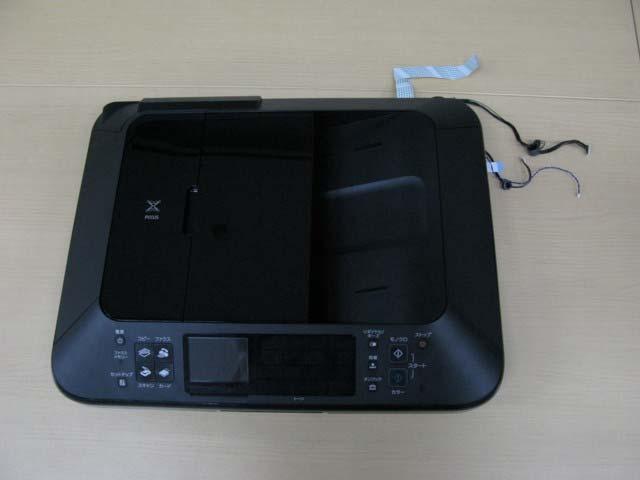
1 MX880 series Service Manual (MX882 / MX883 / MX884 / MX885 / MX886 / MX888) Revision 0 QY8-13DF-000 COPYRIGHT 2011 CANON INC. CANON MX880 series XX
2 Scope This manual has been issued by Canon Inc., to provide the service technicians of this product with the information necessary for qualified persons to learn technical theory, installation, maintenance, and repair of products. The manual covers information applicable in all regions where the product is sold. For this reason, it may contain information that is not applicable to your region. This manual does not provide sufficient information for disassembly and reassembly procedures. Refer to the graphics in the separate Parts Catalog. Revision This manual could include technical inaccuracies or typographical errors due to improvements or changes made to the product. When changes are made to the contents of the manual, Canon will release technical information when necessary. When substantial changes are made to the contents of the manual, Canon will issue a revised edition. The following do not apply if they do not conform to the laws and regulations of the region where the manual or product is used: Trademarks Product and brand names appearing in this manual are registered trademarks or trademarks of the respective holders. Copyright All rights reserved. No parts of this manual may be reproduced in any form or by any means or translated into another language without the written permission of Canon Inc., except in the case of internal business use. Copyright 2011 by Canon Inc. CANON INC. Inkjet Device Market Support Management Div. 451, Tsukagoshi 3-chome, Saiwai-ku, Kawasaki-shi, Kanagawa , Japan
3 MX880 series INTRODUCTION [ How to use this Service Manual ] This manual is intended to solve printer problems smoothly, with each section representing the typical service procedures, as shown below. Troubleshooting Identify the problem, and handle it accordingly. Repair When a part needs to be replaced, see this section. Adjustment & Settings After repair, perform the necessary adjustment and settings. Verification At the end of the servicing, verify the machine following the inspection flow in this section. Appendix Information that will be necessary for maintenance and repair of the machine This manual does not provide sufficient information for disassembly and reassembly procedures. Refer to the graphics in the separate Parts Catalog. <INTRODUCTION>
4 MX880 series TABLE OF CONTENTS 1. TROUBLESHOOTING 1-1. Troubleshooting by Symptom 1-2. Operator Call Error Troubleshooting 1-3. Service Call Error Troubleshooting 1-4. FAX Error Troubleshooting 2. REPAIR 2-1. Major Replacement Parts and Adjustment 2-2. Disassembly & Reassembly Procedures (1) External housing, scanner unit, and document cover removal (2) Operation panel and document feed unit removal (3) Printer unit removal & Ink absorber replacement (4) Board removal (5) Carriage unlocking (6) ASF unit removal (7) Carriage unit removal (8) Spur unit and platen unit removal (9) Purge drive system unit (right plate) and switch system unit (left plate) removal (10) Engine unit reassembly (11) Cable wiring and connection 3. ADJUSTMENT / SETTINGS 3-1. Adjustment 3-2. Adjustment and Maintenance in User Mode 3-3. Adjustment and Settings in Service Mode (1) Service mode operation procedures (2) Service Tool functions (3) LF / Eject correction (4) Button and LCD test (5) Ink absorber counter setting 3-4. Adjustment and Maintenance in PTT Parameter Mode 3-5. Grease Application 3-6. Special Notes on Servicing (1) For smeared printing, uneven printing, or non-ejection of ink (2) Paper feed motor adjustment (3) Carriage unit replacement (4) Document pressure sheet (sponge sheet) replacement (5) Ink absorber counter setting (6) Preventive replacement of ink absorber
5 (7) Power supply unit and modular board replacement (8) Rating label on the bottom case (except China) (9) PTT label on the bottom case (for New Zealand only) (10) Speed Dial Utility 4. VERIFICATION AFTER REPAIR 4-1. Standard Inspection Flow 4-2. Integrated Inspection Pattern Print 4-3. Ink Absorber Counter Value Print 5. APPENDIX 5-1. Customer Maintenance 5-2. Special Tools 5-3. Sensors 5-4. Serial Number Location 6. MACHINE TRANSPORTATION <TABLE OF CONTENTS>
6 MX880 series TABLE OF CONTENTS 1. TROUBLESHOOTING 1-1. Troubleshooting by Symptom Faulty operation Symptom The power does not turn on. The power turns off immediately after power-on. A strange noise occurs. The LCD does not display properly. A portion of the LCD is not displayed. The display flickers. Paper feed problems (multifeeding, skewed feeding, no feeding). Solution (1) Confirm cable connection: - PCI DC harness ass'y => No incomplete connection, cable breakage, or cable caught in units (2) Replace the following item(s): - Logic board ass'y - AC adapter - PCI DC harness ass'y (1) Examine and remove any foreign material from the drive portions. (2) Replace the following item(s): - The part generating the strange noise - Purge drive system unit (1) Confirm cable connection: - LCD cable => No incomplete connection, cable breakage, or cable caught in units (2) Replace the following item(s): - LCD ass'y - LCD cable - Panel board ass'y - Logic board ass'y (1) Examine and remove any foreign material from the following parts: - ASF unit - PE sensor - Paper guide unit - Pressure roller unit - Spur unit (2) Confirm that the paper guides are set properly. (3) Confirm the PF rear cover and the cassette conditions. (4) Confirm cable connection: - PE sensor cable - Paper feed relay harness ass'y => No incomplete connection, cable breakage, or cable caught in units (5) Replace the following item(s): - ASF unit (for paper feeding error from the rear tray) - Pick-up arm unit (for paper feeding error from the cassette) - PE sensor board ass'y - Pressure roller unit 1 / 76
7 - Document feed unit - Cassette unit Unsatisfactory print quality Faulty scanning (no scanning, strange noise). Machine not recognized by a USB-connected computer. No printing, or no color ejected. Faint printing, or white lines on printouts. Uneven printing. Improper color hue. Paper gets smeared. The back side of paper gets smeared. (1) Confirm cable connection: - Scanner motor cable - CIS FFC => No incomplete connection, cable breakage, or cable caught in units (2) Confirm the internal conditions under the platen glass (no damper displaced or caught in units). (3) Replace the following item(s): - Scanner unit - Logic board ass'y (1) Confirm the USB cable connection. (2) Connect the machine to another computer via the USB cable, and check if the machine is recognized. (3) Replace the following item(s): - USB cable - Logic board ass'y See 3-6. Special Notes on Servicing, (1) For smeared printing, uneven printing, or non-ejection of ink, for details. (1) Confirm the ink tank conditions: - No remainder of the outer film (the air-through must be opened) - Whether the ink tank is Canon-genuine one or not - Whether the ink tank is refilled one or not - Re-setting of an ink tank (2) Remove foreign material from the purge unit caps, if any. (3) Confirm the conditions of the carriage head contact pins. (4) Perform cleaning or deep cleaning of the print head. (5) Perform print head alignment. (6) Replace the following item(s): - Print head *1, and ink tanks - Logic board ass'y - Purge drive system unit - Carriage unit (1) Clean the inside of the machine. (2) Perform bottom plate cleaning. (3) Perform paper feed roller cleaning. (4) Replace the following item(s): - Pressure roller ass'y (if smearing is heavy) - Print head *1 (when smearing is caused by the print head) (1) Clean the inside of the machine. (2) Perform bottom plate cleaning. (3) Examine the platen ink absorber. (4) Examine the paper eject roller. (5) Replace the following item(s): 2 / 76
8 Faulty scanning Network connection problem FAX problem Graphic or text is enlarged on printouts in the carriage movement direction. Graphic or text is enlarged on printouts in the paper feed direction. No scanning. Streaks or smears on the scanned image. No printing. No FAX sending or reception. - The part in the paper path causing the smearing (1) Confirm that the carriage slit film is free from smearing or scratches: - Cleaning of the timing slit strip film. (2) Replace the following item(s): - Timing slit strip film - Carriage unit - Logic board ass'y - Scanner unit (for copying) (1) Confirm that the LF / EJ slit film is free from smearing or scratches: - Cleaning of the LF / EJ slit film. (2) Replace the following item(s): - Timing slit disk feed film - Timing slit disk eject film - Timing sensor unit - Platen unit - Logic board ass'y - Scanner unit (for copying) (1) Confirm cable connection. (2) Replace the following item(s): - Scanner unit - Logic board ass'y (1) Clean the platen glass and the document pressure sheet. (2) Confirm the position of the document pressure sheet. (3) Replace the following item(s): - Scanner unit - Document pressure sheet - Logic board ass'y (1) Examine if printing is performed properly via USB connection. (2) Confirm the network connection. (3) Replace the following item(s): - Logic board ass'y - Wireless LAN board ass'y (1) Confirm the FAX settings. (2) Replace the following item(s): - NCU board ass'y - Logic board ass'y *1: Replace the print head only after the print head deep cleaning is performed 2 times, and when the problem persists. 3 / 76
9 1-2. Operator Call Error (by Alarm LED Lit in Orange) Troubleshooting Errors and warnings are displayed by the following ways: 1. Operator call errors are indicated by the Alarm LED lit in orange, and the error and its solution are displayed on the LCD in text and by icon. 2. Messages during printing from a PC are displayed on the printer driver Status Monitor. 3. Error codes (the latest 10 error codes at the maximum) are printed in the "operator call/service call error record" area in EEPROM information print Buttons valid when an operator call error occurs: 1. ON button: To turn the machine off and on again. 2. OK button: To clear and recover from an error. In some operator call errors, the error will automatically be cleared when the cause of the error is eliminated, and pressing the OK button may not be necessary. 3. Stop button: To cancel the job at error occurrence, and to clear the error. Error No paper in the rear tray. No paper in the cassette. Error code U No. Message on the LCD [1000] --- Rear tray. There is no paper. Load paper and press [OK]. [1003] --- Cassette. There is no paper. Load paper and press [OK]. Paper jam. [1300] --- The paper is jammed. Paper jam in [1303] --- Clear the paper and the rear guide. press [OK]. Paper jam in the under guide. Ink may have run out. [1304] --- [1600] U041 The ink may have run out. Replacing the ink tank is recommended. Solution Confirm that the rear tray is selected as the paper source. Set the paper in the rear tray, and press the OK button. If the error is not cleared, confirm that no foreign material is inside the paper feed slot. Confirm that the cassette is selected as the paper source. Set the paper in the cassette, and press the OK button. Note that the cassette is for plain paper only. Remove the jammed paper and press the OK button. For paper jam in the rear guide, confirm that the rear guide is not dislocated. Replace the applicable ink tank, or press the OK button to clear the error without ink tank replacement. When the error is cleared by pressing the OK button, ink may Parts that are likely to be faulty - PE sensor board ass'y - ASF unit - Pressure roller unit - Pick-up arm unit - Pressure roller ass'y - Cassette unit - Pick-up arm unit - ASF unit - Pressure roller ass'y - Cassette unit - Rear guide unit - Spur unit 4 / 76
10 run out during printing. Ink tank not installed. Print head not installed, or not properly installed. Faulty print head ID. Print head temperature sensor error. Faulty EEPROM data of the print head. Multiple ink tanks of the same color installed. Ink tank in a wrong position. Warning: The ink absorber becomes almost full. The connected digital camera or digital video camera does not [1660] U043 The following ink tank cannot be recognized. (Applicable ink tank icon) [1401] U051 Print head is not installed. Install the print head. [1403] [1405] U052 The type of print head is incorrect. Install the correct print head. [1487] U071 More than one ink tank of the following color is installed. [1680] U072 Some ink tanks are not installed in place. [1700] --- The ink absorber is almost full. Press [OK] to continue printing. Contact the service center. [2001] --- Incompatible device detected. Remove the device. Install the applicable ink tank(s) properly, and confirm that the LED's of all the ink tanks light red. Install the print head properly. If the error is not cleared, confirm that the print head contact pins of the carriage are not bent. Re-set the print head. If the error is not cleared, the print head may be defective. Replace the print head. If the error is not cleared, confirm that the print head contact pins of the carriage are not bent. Replace the wrong ink tank (s) with the correct one(s). Install the ink tank(s) in the correct position. Replace the ink absorber, and reset its counter. [See 3-3, Adjustment and Settings in Service Mode.] Pressing the OK button will exit the error, and enable printing without replacing the ink absorber. However, when the ink absorber becomes full, no further printing can be performed unless the applicable ink absorber is replaced. Remove the cable between the camera and the machine. - Ink tank - Carriage unit - Print head - Carriage unit - Print head - Carriage unit - Ink tank - Ink tank - Absorber kit 5 / 76
11 support Camera Direct Printing. Automatic double-sided printing cannot be performed. Failed in automatic print head alignment. The remaining ink amount unknown (raw ink present). Ink tank not recognized. [1310] --- This paper is not compatible with twosided printing. Remove the paper and press [OK]. [2500] --- Auto head align has failed. Press [OK] and repeat operation. <See manual> [1683] U130 The remaining level of the ink cannot be correctly detected. Replace the ink tank. [1684] U140 The following ink tank cannot be recognized. The paper length is not supported for double-sided printing. Press the OK button to eject the paper being used at error occurrence. Data which was to be printed on the back side of paper at error occurrence is skipped (not printed). Press the OK button to clear the error, then perform the automatic print head alignment again. (Use Matte Photo Paper MP-101.) If the alignment pattern was not printed properly (faint printing, etc.), perform print head cleaning, then perform the print head alignment again. An ink tank which has once been empty is installed. Replace the applicable ink tank with a new one. Printing with a once-empty ink tank can damage the machine. To continue printing without replacing the ink tank(s), press the Stop button for 5 sec. or longer to disable the function to detect the remaining ink amount. After the operation, it is recorded in the machine EEPROM that the function to detect the remaining ink amount was disabled. An incompatible ink tank is installed (the ink tank LED is turned off). Install - Duplex paper feed roller unit - PE sensor board ass'y - Carriage unit - Print head - Purge drive system unit - Ink tank - Spur unit - Ink tank 6 / 76
12 (Applicable ink tank icon) the supported ink tanks. Ink tank not recognized. Ink tank not recognized. No ink (no raw ink). Non-supported hub. Document feeder cover not closed. Paper jam in the ADF. No paper in the ADF. [1750] U141 Appropriate ink tank is not installed. Install the appropriate ink tank. [1682] U150 The following ink tank cannot be recognized. (Applicable ink tank icon) [1688] U163 The ink has run out. Replace the ink tank. (Applicable ink tank icon) [2002] --- An unsupported USB hub is connected. Remove the hub. [2800] --- The feeder cover is open. Close cover and press [OK]. [2801] --- Document in ADF. Check document in ADF, then press [OK] and redo operation. [2802] --- No document in ADF. Press [OK], then load document and redo operation. A non-supported ink tank is installed (the ink tank LED is turned off). Install the supported ink tanks. A hardware error occurred in an ink tank (the ink tank LED is turned off). Replace the ink tank(s). Replace the empty ink tank (s), and close the scanning unit (cover). Printing with an empty ink tank can damage the machine. To continue printing without replacing the ink tank(s), press the Stop button for 5 sec. or longer to disable the function to detect the remaining ink amount. After the operation, it is recorded in the machine that the function to detect the remaining ink amount was disabled. Remove the applicable USB hub from the PictBridge (USB) connector. Close the document feeder cover, and press the OK button. Remove the paper from the ADF, and press the OK button. Press the OK button to clear the error. - Ink tank - Ink tank - Ink tank - Spur unit - DF unit - DF switch unit - DF unit - DF unit Paper in the [2803] --- Document size is too Remove the paper from the - DF unit 7 / 76
13 ADF is too long. long. Check document in ADF, then press [OK] and redo operation.. ADF, and press the OK button. Double-sided printing not available with the paper in the ADF. [2804] --- Document size not suitable for duplex scanning. Press [OK] to cancel operation and eject document. Remove the paper from the ADF, and press the OK button. - DF unit Time-out for the scanner device. [2700] --- Timeout error has occurred. Press [OK]. The buffer became full in the middle of scanning operation, and 60 minutes have elapsed since then, making re-scanning unstable. Press the OK button to clear the error. Premium Contents print error. [4100] --- Cannot print the data. Non-genuine ink tanks are installed. Install the supported (Canon-genuine) ink tanks. - Ink tank 1-3. Service Call Error (by Cyclic Blinking of Alarm and Power LEDs) Troubleshooting Service call errors are indicated by the number of cycles the Alarm and Power LEDs blink, and the corresponding error code with the message, "Printer error has occurred. Turn off power then back on again. If problem persists, see the manual." is displayed on the LCD. 1) Check each point in "Check points & Solution," and perform the solution if it applies. 2) When no solution in "Check points & Solution" is effective, then replace the part listed under "Parts to that are likely to be faulty" one by one from the one most likely to be faulty. The parts are listed in the order of likeliness to be faulty. Cycles of blinking of Alarm and Power LEDs Error Error code Check points & Solution Parts that are likely to be faulty (listed in the order of likeliness to be faulty) 2 times Carriage error [5100] (1) Smearing or scratches on the carriage slit film: Clean the film using lint-free paper. (2) Foreign material that obstructs the carriage movement: Remove foreign material. (3) Ink tank conditions: Re-set the ink tanks. (4) Cable connection: - CR FFC (J500, J501, J502, etc.) - Timing slit strip film - Carriage unit - Logic board ass'y - Carriage motor 8 / 76
14 Re-connect the cables. (5) Scratches or damages to the carriage slit film: Replace the timing slit strip film. (6) Black debris around the carriage rail or pressure roller: Replace the carriage unit. 3 times Line feed error [6000] (1) Opening and closing of the paper output tray: Remove obstacles from around the paper output tray so that the tray opens and closes properly. (2) Smearing or scratches on the LF / EJ slit film: Clean the LF / EJ slit film using lint-free paper. (3) Foreign material in the LF drive: Remove foreign material. (4) Cable connection Re-connect the cables. If any damage or breakage of the cable is found, replace the cable. (5) LF lock arm spring: Attach the spring properly. - Timing slit disk feed film - Timing slit disk eject film - Timing sensor unit - Paper feed roller unit - Logic board ass'y - Paper feed motor 4 times Purge cam sensor error 5 times ASF (cam) sensor error 6 times Internal temperature error [5C00] 7 times Ink absorber full [5B00] [5B01] (1) Foreign material around the purge drive system unit: Remove foreign material. (2) Cable connection: - LF encoder cable - PE sensor cable - Paper feed motor harness ass'y Re-connect the cable. (3) Strange sound at power-on: Replace the purge drive system unit. [5700] (1) Cable connection: - PE sensor cable, etc. Re-connect the cable. [5400] (1) Cable connection: - Between the spur unit and the logic board, J703 connector, etc. Re-connect the cable. (1) Ink absorber condition: Replace the ink absorber, and reset the ink absorber counter value in the EEPROM. - Purge drive system unit - Logic board ass'y - ASF unit - PE sensor board ass'y - Logic board ass'y - Spur unit - Logic board ass'y - Print head - Absorber kit 9 / 76
15 8 times Print head temperature rise error 9 times EEPROM error [6800] [6801] [5200] (1) Print head condition (face surface and mold): If a burn mark or heat deformation is seen on the face surface or the mold, replace the print head. (2) Head contact pin condition of the carriage unit: If the pin is bent or deformed, replace the carriage unit. (3) Cable connection: - CR FFC (J500, J501, J502) Re-connect the cable. If any damage or breakage of the cable is found, replace the carriage unit. (1) Part replacement: Replace the logic board ass'y. 10 times VH monitor error [B200] (1) Print head condition (face surface and mold): If a burn mark or heat deformation is seen on the face surface or the mold, replace the print head and the logic board in set. (Be sure to replace them at the same time.) (2) Burn mark or heat deformation of the logic board: If a burn mark or heat deformation is seen on the logic board, replace the print head and the logic board in set. (Be sure to replace them at the same time.) (3) Head contact pin condition of the carriage unit: If the pin is bent or deformed, replace the carriage unit. (4) Cable connection: - CR FFC (J502, J501, J500) Re-connect the cable. If any damage or breakage of the cable is found, replace the carriage unit. 11 times Carriage lift mechanism error [5110] (1) Foreign material that obstructs the carriage movement: Remove foreign material. 12 times APP position error [6A80] (1) Cap absorber and wiper blade of the purge drive system unit: If the cap absorber contacts the - Print head - Carriage unit - Logic board ass'y - Print head and logic board ass'y (replace them at the same time) - AC adapter - Carriage unit - Switch system unit - Carriage unit - Purge drive system unit - Logic board ass'y 10 / 76
16 APP position error during initial purging [6A81] 14 times APP sensor error [6A90] Paper feed cam sensor error 15 times USB host Vbus overcurrent 16 times Pump roller sensor error 17 times Paper eject encoder error [6B10] wiper blade, lower the cap absorber so that it will not contact the wiper blade. (2) Foreign material around the purge drive system unit: Remove foreign material. (3) Ink absorber right beneath the purge drive system unit: Confirm that the absorber stays in place and does not contact the unit. (4) Foreign material around the ASF unit: Remove foreign material. (5) Cable connection: - PE sensor cable - Motor multi harness ass'y Re-connect the cables. If any damage or breakage of the cable is found, replace the cable. (6) APP slit film condition: Clean the APP slit film using lintfree paper. (7) APP code wheel gear condition: If the gear wears, replace the gear. (1) Ink absorber counter value: If the value exceeds 60%, replace the ink absorber. Follow the "Guideline for Preventive Replacement of the Ink Absorber." (2) Jammed paper in the under guide: Remove the jammed paper. [9000] (1) Part replacement: Replace the logic board ass'y. [5C20] (1) Cable connection Re-connect the cable. [6010] (1) Smearing on the LF / EJ slit film: Clean the LF / EJ slit film using lint-free paper. (2) Foreign material in the paper path: Remove foreign material. (3) Cable connection: - LF encoder cable - PE sensor cable Re-connect the cable. (4) Scratches on the LF / EJ slit film: Replace the timing slit disk feed film or the timing slit disk eject film. - Pick-up arm unit - Duplex paper feed roller unit - Purge drive system unit - Timing slit disk feed film - Timing slit disk eject film - Timing sensor unit - Platen unit - Logic board ass'y - Paper feed motor 11 / 76
17 19 times Ink tank position sensor error [6502] (1) Ink tank position: Confirm the ink tanks are installed in the correct slots. (2) Re-set or replacement of ink tanks: If the error persists, replace the ink tanks. (3) Cable connection Re-connect the cable. 20 times Other errors [6500] (1) Cable connection: - Wireless LAN cable Re-connect the cable. 21 times Drive switch error [C000] (1) Foreign material in the drive switch area of the purge drive system unit: Remove foreign material. (2) Ink tank conditions: Confirm that the ink tanks are seated properly and they do not interfere with the carriage movement. 22 times Scanner error [5011] (1) Cable connection: - J900, J1103, J704 Re-connect the cable. (2) Damper condition inside the scanner: If the damper winds around the CIS, replace the scanner unit. (3) Scanner belt pulley: If the pulley is dislocated, replace the scanner unit. (4) Document pressure sheet conditions: Re-attach the document pressure sheet, or replace it. FB motor error [5012] (1) Cable connection: - J900, J1103, J704 Re-connect the cable. 23 times Valve cam sensor error [6C10] (1) Foreign material around the purge drive system unit: Remove foreign material. (2) Cable connection: - J702 connector Re-connect the cable. - Spur unit - Logic board ass'y - Logic board ass'y - Wireless LAN board ass'y - Purge drive system unit - ASF unit - Carriage unit - Scanner unit - Document pressure sheet - Logic board ass'y - Scanner unit - Purge drive system unit - Logic board ass'y Before replacement of the logic board, check the ink absorber counter value, and register it to the replaced new logic board. (The value can be set in 10% increments.) In addition, according to the "Guideline for Preventive Replacement of Ink Absorber," replace the ink absorber. [See 3. ADJUSTMENT / SETTINGS, 3-3. Adjustment and Settings in Service Mode, for details.] 12 / 76
18 1-4. FAX Error Troubleshooting For errors other than those listed below, please refer to the "G3 / G4 Facsimile Error Code List (Rev. 2." (HY8-23A0-020 in English, HY8-22A6-020 in Japanese). (1) User error codes Error code TX / RX Meaning Solution (Parts that are likely to be faulty) #001 TX Document jam - DF unit #003 TX / RX Document is too long, or page time-over - DF unit #005 TX / RX Initial identification (T0 / T1) time-over - Check the telephone line type settings (rotary pulse / touch tone). #009 RX Recording paper jam, or no recording paper - ASF unit - Pick-up arm unit - Cassette unit - Pressure roller unit #012 TX No recording paper at the receiving machine #017 TX Redial time-over, but no DT detected #018 TX Auto dialing transmission error, or redial timeover - Check the telephone line type settings (rotary pulse / touch tone). #022 TX Call failed (no dial registration) - Register a dial number. #037 RX Memory overflow at reception of an image - Delete unnecessary image data from the memory. #085 TX No color fax function supported in the receiving machine #099 TX / RX Transmission terminated mid-way by pressing the Stop button #995 TX / RX During TX (sending): Memory transmission reservation cancelled During RX (receiving): Image data received in the memory cleared - Send a fax in the B&W mode. (2) Service error codes Error code TX / RX Meaning Solution (Parts that are likely to be faulty) ##100 TX Re-transmission of the procedure signal has been attempted the specified number of times, but failed. ##101 TX / RX Sender's modem speed does not match the receiving machine. - Try a higher transmission level. ##102 TX Fallback is not available. - Try a higher transmission level. ##103 RX EOL has not been detected for 5 seconds (or 15 - Increase the transmission level of the 13 / 76
19 seconds in CBT). sending machine. ##104 TX RTN or PIN has been received. - Try a higher transmission level. ##106 RX The procedure signal has been expected for 6 seconds, but not received. - Increase the transmission level of the sending machine. ##107 RX Fallback is not available at the sending machine. - Increase the transmission level of the sending machine. ##109 TX After DCS transmission, a signal other than DIS, DTC, FTT, CFR, or CRP has been received, and re-transmission of the procedure signal has been attempted the specified number of times but failed. ##111 TX / RX Memory error - Eliminate all the data, and register them again. ##114 RX RTN has been received. - Increase the transmission level of the sending machine. ##200 RX A carrier has not been detected for 5 seconds during image reception. ##201 TX / RX DCN has been received in a method other than the binary procedure. ##204 TX DTC has been received even when there is no sending data. - Increase the transmission level of the sending machine. - Set the other machine ready for reception. ##220 TX / RX System error (main program hang-up) - Turn the machine off, and turn it on again - Modular board - Logic board ##224 TX / RX An error has occurred in the procedure signal in G3 transmission. ##226 TX / RX The stack pointer has shifted from the RAM area. - Turn the machine off, and turn it on again. ##229 RX The recording area has been locked for 1 minute. - After the area is unlocked, print the recorded image. ##232 TX The encoder control unit has malfunctioned. - Modular board - Logic board ##237 RX The decoder control unit has malfunctioned. - Modular board - Logic board ##238 RX The print control unit has malfunctioned. - Modular board - Logic board ##261 TX / RX A system error has occurred between the modem and the system control board. ##280 TX Re-transmission of the procedure signal has been attempted the specified number of times, but - Modular board - Logic board - Try a higher transmission level. 14 / 76
20 failed. ##281 TX Re-transmission of the procedure signal has been attempted the specified number of times, but failed. ##282 TX Re-transmission of the procedure signal has been attempted the specified number of times, but failed. ##283 TX Re-transmission of the procedure signal has been attempted the specified number of times, but failed. - Try a higher transmission level. - Try a higher transmission level. - Try a higher transmission level. ##284 TX After TCF transmission, DCN has been received. - Set the receiving machine ready for reception. ##285 TX After EOP transmission, DCN has been received. - Re-send the fax. ##286 TX After EOM transmission, DCN has been received. - Re-send the fax. ##287 TX After MPS transmission, DCN has been received. - Re-send the fax. ##288 TX After EOP transmission, a signal other than PIN, PIP, MCF, RTP, RTN has been received. ##289 TX After EOM transmission, a signal other than PIN, PIP, MCF, RTP, RTN has been received. ##290 TX After MPS transmission, a signal other than PIN, PIP, MCF, RTP, RTN has been received. ##670 TX In V.8 late start, the DIS V.8 ability from the receiving machine was detected, and CI was sent in response; however, the procedure failed, causing T1 time-over. - In bit 0 of the service data #1 SSSW SW28, prohibit the V.8 / V.34 procedure of the sending machine. ##671 RX In V.8 call reception, the procedure fails to proceed to phase 2 after CM detection, causing T1 time-over. ##672 TX In V.34 transmission, the procedure fails to proceed from phase 2 to phase 3 or later, causing T1 time-over ##673 RX In V.34 reception, the procedure fails to proceed from phase 2 to phase 3 or later, causing T1 timeover ##674 TX In V.34 transmission, the procedure fails to proceed from phase 3 or 4 to the control channel or later, causing T1 time-over ##675 RX In V.34 reception, the procedure fails to proceed from phase 3 or 4 to the control channel or further, causing T1 time-over - In bit 0 of the service data #1 SSSW SW28, prohibit the V.8 / V.34 procedure of the sending machine. - In bit 0 of the service data #1 SSSW SW28, prohibit the V.8 / V.34 procedure of the sending machine. - In bit 0 of the service data #1 SSSW SW28, prohibit the V.8 / V.34 procedure of the sending machine. - In bit 0 of the service data #1 SSSW SW28, prohibit the V.8 / V.34 procedure of the sending machine. - In bit 0 of the service data #1 SSSW SW28, prohibit the V.8 / V.34 procedure of the sending machine. ##750 TX After transmitting PPS-NULL in ECM - Try a higher transmission level. 15 / 76
21 transmission, no significant signal has been received, and re-transmission of the procedure signal has been attempted the number of specified times but failed. ##752 TX After transmitting PPS-NULL in ECM transmission, DCN has been received. ##753 TX After transmitting PPS-NULL in ECM transmission, re-transmission of the procedure signal has been attempted the number of specified times but failed, or T5 time-over (60 sec.) has occurred. ##754 TX After transmitting PPS-NULL in ECM transmission, re-transmission of the procedure signal has been attempted the number of specified times but failed. ##755 TX After transmitting PPS-MPS in ECM transmission, no significant signal has been received, and re-transmission of the procedure signal has been attempted the number of specified times but failed. ##757 TX After transmitting PPS-MPS in ECM transmission, DCN has been received. ##758 TX After transmitting PPS-MPS in ECM transmission, re-transmission of the procedure signal has been attempted the number of specified times but failed, or T5 time-over (60 sec.) has occurred. ##759 TX After transmitting PPS-MPS in ECM transmission, re-transmission of the procedure signal has been attempted the number of specified times but failed. ##760 TX After transmitting PPS-EOM in ECM transmission, no significant signal has been received, and re-transmission of the procedure signal has been attempted the number of specified times but failed. ##762 TX After transmitting PPS-EOM in ECM transmission, DCN has been received. ##763 TX After transmitting PPS-EOM in ECM transmission, re-transmission of the procedure signal has been attempted the number of specified times but failed, or T5 time-over (60 sec.) has occurred. - Try a higher transmission level. - Increase the period of time of the T5 time-over. - Try a higher transmission level. - Try a higher transmission level. - Try a higher transmission level. - Increase the period of time of the T5 time-over. - Try a higher transmission level. - Try a higher transmission level. - Try a higher transmission level. - Increase the period of time of the T5 time-over. ##764 TX After transmitting PPS-EOM in ECM - Try a higher transmission level. 16 / 76
22 transmission, re-transmission of the procedure signal has been attempted the number of specified times but failed. ##765 TX After transmitting PPS-EOP in ECM transmission, no significant signal has been received, and re-transmission of the procedure signal has been attempted the number of specified times but failed. ##767 TX After transmitting PPS-EOP in ECM transmission, DCN has been received. ##768 TX After transmitting PPS-EOP in ECM transmission, re-transmission of the procedure signal has been attempted the number of specified times but failed, or T5 time-over (60 sec.) has occurred. ##769 TX After transmitting PPS-EOP in ECM transmission, re-transmission of the procedure signal has been attempted the number of specified times but failed. ##770 TX After transmitting EOR-NULL in ECM transmission, no significant signal has been received, and re-transmission of the procedure signal has been attempted the number of specified times but failed. ##772 TX After transmitting EOR-NULL in ECM transmission, DCN has been received. ##773 TX After transmitting EOR-NULL in ECM transmission, re-transmission of the procedure signal has been attempted the number of specified times but failed, or T5 time-over (60 sec.) has occurred. ##774 TX After transmitting EOR-NULL in ECM transmission, ERR has been received. ##775 TX After transmitting EOR-MPS in ECM transmission, no significant signal has been received, and re-transmission of the procedure signal has been attempted the number of specified times but failed. ##777 TX After transmitting EOR-MPS in ECM transmission, DCN has been received. ##778 TX After transmitting EOR-MPS in ECM transmission, re-transmission of the procedure signal has been attempted the number of specified times but failed, or T5 time-over (60 - Increase the transmission level of the receiving machine. - Try a higher transmission level. - Increase the transmission level of the receiving machine. - Try a higher transmission level. - Increase the period of time of the T5 time-over. - Try a higher transmission level. - Increase the transmission level of the receiving machine. - Try a higher transmission level. - Increase the transmission level of the receiving machine. - Try a higher transmission level. - Increase the period of time of the T5 time-over. - Try a higher transmission level. - Try a higher transmission level. - Try a higher transmission level. - Increase the period of time of the T5 time-over. 17 / 76
23 sec.) has occurred. ##779 TX After transmitting EOR-MPS in ECM transmission, ERR has been received. ##780 TX After transmitting EOR-EOM in ECM transmission, no significant signal has been received, and re-transmission of the procedure signal has been attempted the number of specified times but failed. ##782 TX After transmitting EOR-EOM in ECM transmission, DCN has been received. ##783 TX After transmitting EOR-EOM in ECM transmission, re-transmission of the procedure signal has been attempted the number of specified times but failed, or T5 time-over (60 sec.) has occurred. ##784 TX After transmitting EOR-EOM in ECM transmission, ERR has been received. ##785 TX After transmitting EOR-EOP in ECM transmission, no significant signal has been received, and re-transmission of the procedure signal has been attempted the number of specified times but failed. ##787 TX After transmitting EOR-EOP in ECM transmission, DCN has been received. ##788 TX After transmitting EOR-EOP in ECM transmission, re-transmission of the procedure signal has been attempted the number of specified times but failed, or T5 time-over (60 sec.) has occurred. ##789 TX After transmitting EOR-EOP in ECM transmission, ERR has been received. ##790 RX After receiving EOR-EOP in ECM reception, ERR has been transmitted. ##791 TX / RX During the ECM mode procedure, a signal other than a significant one has been received. ##792 RX In ECM reception, PPS-NULL between partial pages has not been detected. ##793 RX During high-speed signal reception in ECM, no effective frame has been detected, and a timeover has occurred. - Try a higher transmission level. - Increase the transmission level of the receiving machine. - Increase the transmission level of the receiving machine. - Increase the period of time of the T5 time-over. - Try a higher transmission level. - Try a higher transmission level. - Increase the transmission level of the receiving machine. - Try a higher transmission level. - Increase the period of time of the T5 time-over. - Try a higher transmission level. - Increase the transmission level of the sending machine. - Increase the transmission level of the sending machine. - Try a higher transmission level. - Increase the transmission level of the sending machine. <1. TROUBLESHOOTING> 18 / 76
24 MX880 series TABLE OF CONTENTS 2. REPAIR 2-1. Major Replacement Parts and Adjustment Service part Logic board ass'y Absorber kit Recommended removal procedure *1 / Notes on replacement (1) Cassette unit (2) Left and right side covers (3) Document pressure plate unit (4) Scanner unit (5) Main case (6) Rear cover (7) Logic board ass'y - Before replacement, check the ink absorber counter value (by service test print or EEPROM information print). - Before removal of the logic board ass'y, remove the power cord, and allow for approx. 1 minute (for discharge of capacitor's accumulated charges), to prevent damages to the logic board ass'y. (1) Cassette unit (2) Left and right side covers (3) Document pressure plate unit (4) Scanner unit (5) Main case (6) Rear cover (7) Print unit (8) Ink absorber Adjustment / settings / operation check In the service mode: 1. Set the ink absorber counter value. 2. Set the destination. 3. Print the integrated inspection pattern. 4. Perform LF / Eject correction (only when streaks or uneven printing occurs). 5. Print the EEPROM information. [See 3-3. Adjustment and Settings in Service Mode, for details.] In the user mode: 6. Set the language displayed on the LCD. 7. Reset the LAN settings. 8. Perform print head alignment. 9. Print via USB connection. 10. Copy. 11. Perform direct printing from a digital camera (PictBridge). In the service mode: 1. Reset the ink absorber counter. After the ink absorber counter is reset, the counter value is printed automatically [See 3-3. Adjustment and Settings in Service Mode, for details.]. Carriage unit - See 2-2. Disassembly & Reassembly Procedures, (3) Printer unit removal & Ink absorber replacement, for details. (1) Cassette unit (2) Left and right side covers (3) Document pressure plate unit (4) Scanner unit (5) Main case (6) Rear cover (7) Timing slit strap - Before removal of the carriage rail, put a mark of the carriage rail position. (8) Carriage rail (9) Carriage unit 1. Apply grease to the sliding portions of the carriage rail. [See 3-5. Grease Application, for details.] In the service mode: 2. Print the integrated inspection pattern. [See 3-3. Adjustment and Settings in Service Mode, for details.] In the user mode: 3. Perform automatic print head alignment. 19 / 76
25 Switch system unit - Keep the timing slit strip film (carriage encoder film) free from stain or damage. When returning the film, make sure of its orientation (left and right, front and back). - See 2-2. Disassembly & Reassembly Procedures, (7) Carriage unit removal, for details. (1) Cassette unit (2) Left and right side covers (3) Document pressure plate unit (4) Scanner unit (5) Main case (6) Rear cover (7) Print unit (8) See 2-2. Disassembly & Reassembly Procedures. 1. Adjust the paper feed motor. [See 3-6. Special Notes on Servicing, (2) Paper feed motor adjustment, for details.] In the service mode: 2. Print the integrated inspection pattern. Paper feed motor - See 2-2. Disassembly & Reassembly Procedures, (9) Purge drive system unit (right plate) and switch system unit (left plate) removal, for details. - See 2-2. Disassembly & Reassembly Procedures, (10) Engine unit reassembly, for details. - The screws securing the paper feed motor are allowed to be loosened only for paper feed motor replacement. (DO NOT loosen them in any other cases.) Platen unit (1) Cassette unit (2) Left and right side covers (3) Document pressure plate unit (4) Scanner unit (5) Main case (6) Rear cover (7) Print unit (8) See 2-2. Disassembly & Reassembly Procedures, from this step. Spur unit (1) Cassette unit (2) Left and right side covers (3) Document pressure plate unit (4) Scanner unit (5) Main case (6) Rear cover (7) Print unit (8) See 2-2. Disassembly & Reassembly Procedures. In the service mode: 1. Perform LF / Eject correction (only when uneven printing or streaks appear on printouts after replacement). [See 3-3. Adjustment and Settings in Service Mode, for details.] 2. Print the integrated inspection pattern. In the service mode: 1. Print the integrated inspection pattern. 2. Perform LF / Eject correction (only when uneven printing or streaks appear on printouts after replacement). [See 3-3. Adjustment and Settings in Service Mode, for details.] 20 / 76
26 Purge drive system unit - DO NOT contact the spur edges. (1) Cassette unit (2) Left and right side covers (3) Document pressure plate unit (4) Scanner unit (5) Main case (6) Rear cover (7) Print unit (8) See 2-2. Disassembly & Reassembly Procedures. In the service mode: 1. Print the integrated inspection pattern. Carriage rail and main chassis Idler pulley parallel pin APP code wheel gear shaft Document pressure sheet Document pressure plate Scanner unit LCD ass'y - See 2-2. Disassembly & Reassembly Procedures, (9) Purge drive system unit (right plate) and switch system unit (left plate) removal, for details. - See 2-2. Disassembly & Reassembly Procedures, (10) Engine unit reassembly, for details. See 2-2. Disassembly & Reassembly Procedures, and Parts Catalog. (1) Cassette unit (2) Left and right side covers (3) Document pressure plate unit (4) Scanner unit (1) Panel cover (2) Operation panel (3) LCD ass'y - Be cautious not to scratch or damage the LCD cable. Timing slit See 2-2. Disassembly & Reassembly 1. Apply grease to the sliding portions. [See 3-5. Grease Application, for details.] In the service mode: 2. Print the integrated inspection pattern. 1. Confirm the document pressure plate sheet position. [See 3-6. Special Notes on Servicing, (4) Document pressure sheet replacement, for details.] In the service mode: 2. Print the integrated inspection pattern. In the service mode: 1. Perform button and LCD test. [See 3-3. Adjustment and Settings in Service Mode, for details.] 2. Print the integrated inspection pattern. In the user mode: 21 / 76
27 strip film Timing slit disk feed film Timing slit disk eject film Print head Procedures, and Parts Catalog. - Upon contact with the film, wipe the film with ethanol. - Confirm no grease is on the film. (Wipe off any grease thoroughly with ethanol.) - Do not bend the film. 1. Perform print head alignment. In the service mode: 2. Print the nozzle check pattern. 3. Perform LF / Eject correction (only when uneven printing or streaks appear on printouts after replacement). [See 3-3. Adjustment and Settings in Service Mode, for details.] In the user mode: 1. Perform print head alignment. Wireless LAN board ass'y (1) Cassette unit (2) Left and right side covers (3) Document pressure plate unit (4) Scanner unit (5) Main case (6) WLAN board In the service mode: 2. Print the integrated inspection pattern. In the user mode: 1. Reset the LAN settings. In the service mode: 2. Print the integrated inspection pattern, and confirm that the WLAN MAC address is properly updated. *1: To reassemble the unit after replacement, follow the procedures in the reverse order. General notes: - Make sure that the flexible cables and wires in the harness are in the proper position and connected correctly. See 2-2. Disassembly & Reassembly Procedures or the Parts Catalog for details. - Do not drop the ferrite core, which may cause damage. - Protect electrical parts from damage due to static electricity. - Before removing a unit, after removing the power cord, allow the machine to sit for approx. 1 minute (for capacitor discharging to protect the logic board ass'y from damages). - Do not touch the timing slit strip film, timing slit disk feed film, and timing slit disk eject film. No grease or abrasion is allowed. - Protect the units from soiled with ink. - Protect the housing from scratches. - Exercise caution with the screws, as follows: i. The screws of the paper feed motor may be loosened only at replacement of the paper feed motor unit (DO NOT loosen them in other cases). ii. Before loosening the 3 screws that fix the carriage rail to the main chassis, mark the screw positions so that the carriage rail will be re-attached to the main chassis in its original position. [See 2-2. Disassembly & Reassembly Procedures, (7) Carriage unit removal, for details.] <2-1. Major Replacement Parts and Adjustment> 22 / 76
 Be sure to protect the machine from static electricity in repair servicing, especially for the LCD, operation")

 External housing, scanner unit, and document cover removal 1) Remove the cassette and the rear guide unit.")

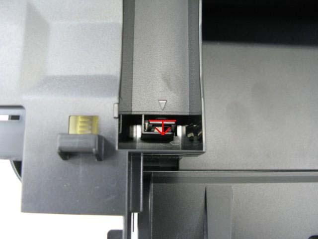
28 MX880 series TABLE OF CONTENTS 2-2. Disassembly & Reassembly Procedures (Click on the image to enlarge it.) Be sure to protect the machine from static electricity in repair servicing, especially for the LCD, operation panel board, scanner unit, logic board, card board, WLAN board, NCU board, and PE sensor board. Some of the photos below are for the MX860 and MX870, since their structure is similar to that of the MX880 series. (1) External housing, scanner unit, and document cover removal 1) Remove the cassette and the rear guide unit. (no screws) 2) Remove the AC adapter. (1 screw) <Pull out the AC adapter from the bottom of the bottom case.> <The core fits to the AC adapter rib.> See "3-6. Special Notes on Servicing, (7) Power supply unit and modular board replacement." 3) Remove the side cover R. (2 screws) <The scanner unit hinges are fitted in the right and left side covers.> 23 / 76


 <The")

29 4) Remove the scanner cable, LCD cable, document feeder harness, panel ground harness, and core. (1 screw) <The core fits to the main case rib.> 24 / 76


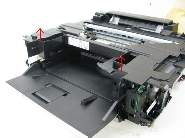
30 5) Remove the side cover L, disengage the scanner support, then separate the scanner from the printer. (4 screws) 25 / 76


31 6) Separate the scanner from the document feeder. (no screws) 7) Remove the document feed cover where the emblem is attached. (no screws) 27 / 76

")
32 8) Remove the main case. (no screws) 28 / 76


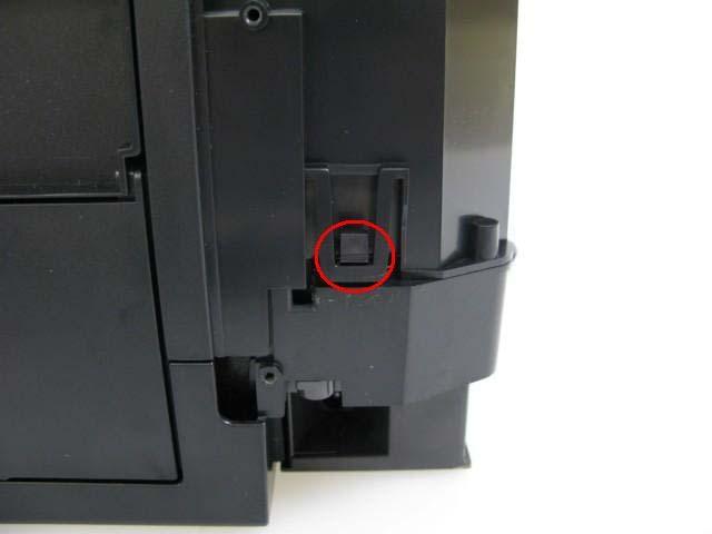
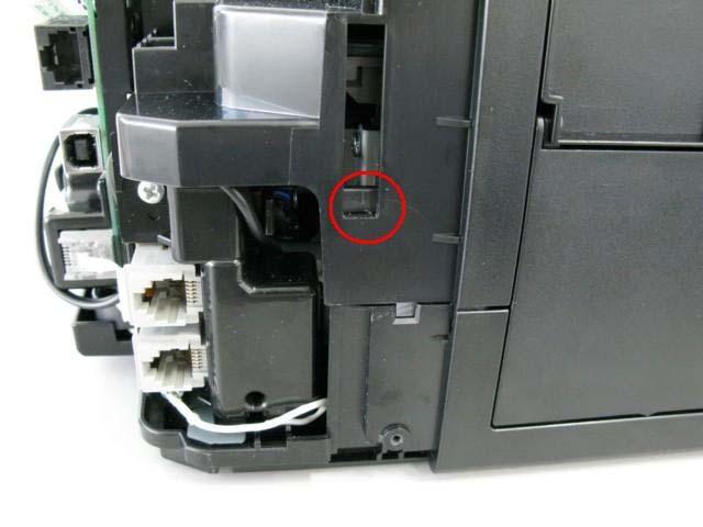
33 (2) Operation panel and document feed unit removal 1) Remove the panel cover, right cover, and rear cover. (no screws) <Be cautious not to damage the tabs and hooks.> 29 / 76

 Remove the")

 <The")

34 2) Remove the document feed cover. 3) Remove the operation panel, document feed tray, eject tray, and document feed unit. (16 screws) <The core fits to the document feed base rib.> 30 / 76


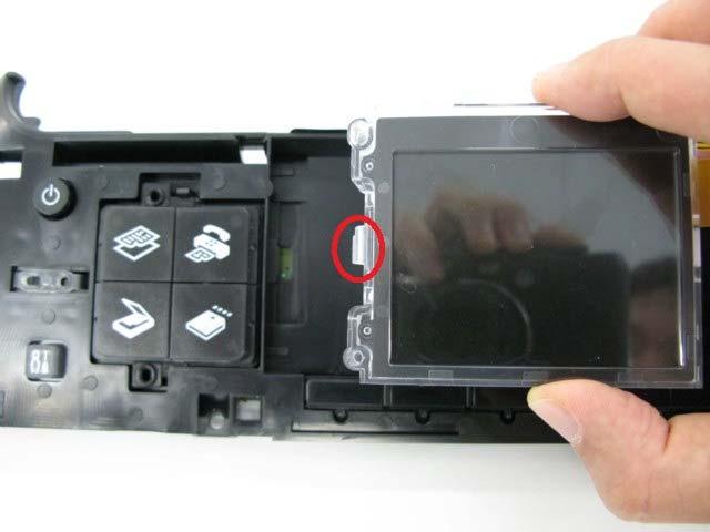
35 4) Remove the LCD ass'y. (no screws) 31 / 76
.")
")

 2) Separate the")
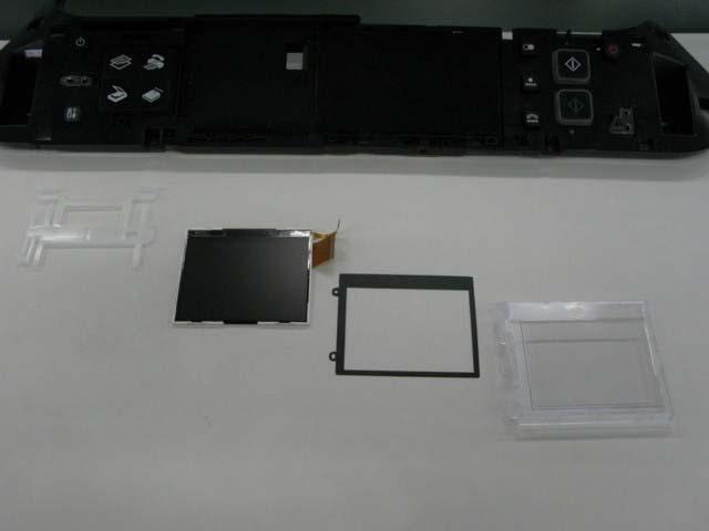
36 5) Remove the panel board (10 screws). (3) Printer unit removal, and ink absorber replacement 1) Separate the PictBridge chassis from the main PCB chassis. (1 screw) 2) Separate the main PCB chassis from the bottom case. (1 screw) 32 / 76

 <The GND")


37 3) Separate the PCI DC and GND harnesses from the printer unit. (1 screw) <The GND harness fits to the bottom case rib.> See "3-6. Special Notes on Servicing, (7) Power supply unit and modular board replacement." 33 / 76


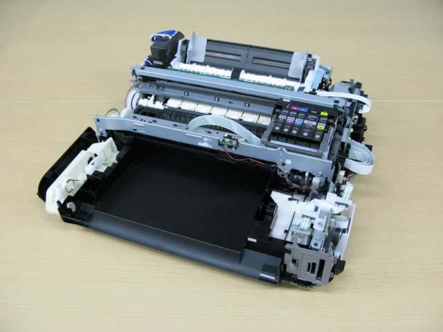
38 4) Remove the speaker. (2 screws) 5) Remove the printer unit. (6 screws) <While being cautious not to damage the arm that connects to the front door, lift the printer unit.> 34 / 76
: When the paper separation")


39 Specific screw location (photos are from the MG5200 series): When the paper separation slope is removed as well as the printer unit from the bottom case, ink absorbers can be replaced. Some of the ink absorbers are under the paper separation slope. When the ink absorbers are replaced, confirm that the replaced new absorbers fit in place securely, and they do not lift. After replacement of the ink absorbers, reset the ink absorber counter value to zero in the service mode. [See 3-3. Adjustment and Settings in Service Mode, for details.] 35 / 76
 Remove the")


 <The")

40 (4) Board removal 1) Remove the WLAN board, card board, main PCB, modular board, and main PCB chassis. (13 screws) <The core fits to the rib of the harness guide.> 36 / 76


41 2) Remove the PE sensor board. (5 screws) (5) Carriage unlocking 1) Rotate the drive unit gear toward the back of the machine to unlock the carriage. Slide the carriage to the left (the opposite of the home position). 37 / 76
")


42 (6) ASF unit removal 1) Remove 1 screw from the left plate, and 2 screws from the right plate. 38 / 76

.")


43 (7) Carriage unit removal 1) On the main chassis, mark the positions of the screws that fix the carriage rail to the main chassis (3 points for each screw: the left, right, and center). 2) Remove the timing slit film. Be cautious to keep it free from any grease or damage. 3) Using a pair of pliers, etc., release the left end of the pulley holder spring, then remove the carriage belt. Be cautious to keep it free from any grease. 39 / 76


44 4) Remove 3 screws that fix the carriage rail to the main chassis. Before removing the center screw, remove the carriage cable holder from the front chassis. After the 3 screws are removed, slowly put down the carriage rail. 5) Remove the carriage unit. Be cautious that the grease will not attach to any parts. 40 / 76
 Remove the ink sensor")
.")

.")

45 (8) Spur unit and platen unit removal 1) Remove the ink sensor and the middle front cover from the front chassis (1 screw each). 2) From the left and right sides of the spur unit, release the springs (2 on the left side, 1 on the right side). Then, slowly pull the spur unit upward to remove it from the platen unit. 41 / 76

 Unlock the")


46 3) Remove the front chassis (3 screws). 4) Unlock the paper eject roller gear. While raising the front of the platen unit, remove the platen unit from the printer unit. 42 / 76
 and switch system unit (left")


.")
 2) Remove the pressure roller")
47 (9) Purge drive system unit (right plate) and switch system unit (left plate) removal 1) Remove the carriage motor cable, duplex printing paper feed roller, cassette feed roller, cassette feed guide, paper guide unit, and springs of the paper guide unit (both sides). (See the Parts Catalog for details.) 2) Remove the pressure roller springs (4 springs). 43 / 76


 Separate")


48 3) Remove the screws that fix the units to the main chassis (2 on the right, 3 on the left). 4) Separate the main chassis from the switch system unit and the purge drive system unit. 44 / 76
 Install the switch system unit in the bottom case, and fasten the screws.")
 Install the cassette feed roller unit. 5) Install the paper feed roller unit and attach the paper feed belt.")
49 (10) Engine unit reassembly After repair, reassemble each unit of the printer engine on the bottom case in the procedures listed below. Depending on the replaced unit, some steps can be omitted. For specific part names and locations, refer to the Parts Catalog. 1) Install the switch system unit in the bottom case, and fasten the screws. 2) Attach the duplex print paper feed roller unit to the purge drive system unit, and fix them to the bottom case with the screws. 3) Attach the cassette feed guide. 4) Install the cassette feed roller unit. 5) Install the paper feed roller unit and attach the paper feed belt. 6) Attach the paper guide unit to the paper feed roller, and attach the springs to each side of the guide unit. (Hook the other end of each spring on the protrusion of the right and left plates respectively.) 7) Install the platen unit and the spur unit. 8) Connect the springs on each side of the spur holder to the switch system unit and the purge drive system unit respectively. 9) Fix the pressure roller unit to the main chassis (screw it to the right and left plates). 10) Attach the carriage unit and the carriage rail to align with the marks on the main chassis. 11) Hook the torsion springs of the pressure roller unit to the main chassis, then the springs kept at the right and left plates in step 6) to the main chassis. Springs hooked at the right and left plates in step 6): 12) While being cautious not to damage the carriage FFC, install the front chassis and the ground chassis. 13) Attach the ink sensor board to the front chassis. 14) Install the ASF unit and attach the PE sensor board. 15) Install the main PCB chassis. 16) Arrange each harness. 17) Attach the carriage encoder. 18) Install the logic board. 45 / 76
 Main PCB")


50 (11) Cable wiring and connection 1) Main PCB and spur unit: 2) Switch system unit and PE sensor board: <2-2. Disassembly & Reassembly Procedures> 46 / 76
51 MX880 series TABLE OF CONTENTS 3. ADJUSTMENT / SETTINGS 3-1. Adjustment Adjustment Purpose Method Destination settings (EEPROM settings) Ink absorber counter resetting (EEPROM settings) Ink absorber counter value setting (EEPROM settings) Paper feed motor position adjustment Automatic print head alignment Manual print head alignment Grease application Ink system function check To set the machine destination. - At logic board replacement To reset the ink absorber counter. - At ink absorber replacement To set the data of the actual ink amount absorbed in the ink absorber to the EEPROM. - At logic board replacement To adjust the belt tension. (Position the paper feed motor so that the belt is stretched tight.) - At paper feed motor replacement To secure the dot placement accuracy. - At print head replacement - At logic board replacement - When print quality is not satisfying To secure the dot placement accuracy. - At print head replacement - At logic board replacement - When print quality is not satisfying even after automatic print head alignment is performed To maintain sliding properties of the applicable portions. - At carriage unit replacement - At APP motor replacement To maintain detection functionality for presence of the ink tanks and each ink tank position. - At logic board replacement - At spur unit replacement - At carriage unit replacement Service Tool *1, Set Destination section Service Tool *1, Main in the Clear Ink Counter section Service Tool *1, Ink Absorber Counter section Fix the paper feed motor so that the belt is stretched tight. (See 3-6. Special Notes on Servicing, (2) Paper feed motor adjustment, for details.) Perform automatic print head alignment in the user mode. Recommended for the MX880 series. Perform manual print head alignment in the user mode. Using a brush, etc., apply FLOIL KG-107A. (See 3-5. Grease Application, for details.) Service Tool *1, Test Print in the Print section Approx. time 1 min. 1 min. 1 min. 5 min. 6 min. 10 min. 1 min. 1 min. 47 / 76
52 LCD language settings Platen glass protection sheet (document pressure sheet) position adjustment LF / Eject correction Carriage rail position adjustment FAX user data settings To set the language to be displayed on the LCD. Not necessary when the machine is set to the default at shipment from the production site (On arrival at user's, the user is to set the language during setup.). - At logic board replacement To maintain scanning accuracy, hold the sheet with the long side down, then fit its upper left corner to the platen glass reference mark (back left). - At protection sheet replacement - At document pressure plate unit replacement - At scanner unit replacement To correct line feeding when necessary. - At paper feed roller replacement - At platen unit replacement - At logic board replacement - At LF / EJ slit film replacement - At timing slit film replacement To set the carriage rail to the original position prior to removal or replacement of the carriage unit and maintain the head-to-paper distance, put a mark on the main chassis before removal of the carriage unit. To confirm the FAX user data settings. - At logic board replacement - At NCU board replacement *1: Install the Service Tool to a pre-registered computer. Set the language in the user mode. In the user mode: (1) Without any document on the platen glass, perform copying. (2) Confirm that no black streaks are on the printout. Service Tool *1, (1) In the LF/EJECT Correction section, click Print to print the LF/EJ correction pattern. (2) According to the printed pattern, set the correction value in the LF/EJECT Correction section. Put a mark using a sharppointed metallic stick, such as a wimble. Perform settings in the user mode. 1 min. 1 min. 5 min. 1 min. 2 min. - The screws securing the paper feed motor may be loosened only at replacement of the paper feed motor unit. - For the automatic print head alignment, use Matte Photo Paper (MP-101), which is packed with the machine before shipment. If Matte Photo Paper (MP-101) is not available, perform manual print head alignment using plain paper. 48 / 76
53 3-2. Adjustment and Maintenance in User Mode Function Procedures Remarks Nozzle check pattern printing Print head manual cleaning Print head deep cleaning Automatic print head alignment Manual print head alignment Print head alignment value printing Paper feed roller cleaning Bottom plate cleaning Perform from the printer driver Maintenance tab, or via the machine operation panel. - Cleaning both Black and Color: Perform via the machine operation panel, or from the printer driver Maintenance tab. - Cleaning Black or Color separately: Perform from the printer driver Maintenance tab. Perform via the machine operation panel, or from the printer driver Maintenance tab. Perform via the machine operation panel, or from the printer driver Maintenance tab. Perform from the printer driver Maintenance tab. Perform via the machine operation panel, or from the printer driver Maintenance tab. Perform via the machine operation panel, or from the printer driver Maintenance tab. Perform via the machine operation panel, or from the printer driver Maintenance tab. Set a sheet of plain paper (A4 or Letter) in the cassette, or the rear tray if selected. Unclogging of the print head nozzles, and maintenance to keep the print head conditions good. If there is a missing portion or white streaks in the nozzle check pattern printout, perform this cleaning. If print head manual cleaning is not effective, perform this cleaning. Since the deep cleaning consumes more ink than regular cleaning, it is recommended to perform deep cleaning only when necessary. Set a sheet of Matte Photo Paper MP-101 (A4) in the rear tray. If the automatic print head alignment is not effective, perform manual print head alignment. Set 3 sheets of plain paper (A4 or Letter) in the cassette, or the rear tray if selected. Confirmation of the current print head alignment values. The paper feed rollers of the selected paper source (the rear tray or the cassette) rotate while being pushed to the paper lifting plate. Since the rollers will wear out in this cleaning, it is recommended that you perform this only when necessary. Cleaning of the platen ribs when the back side of paper gets smeared. Fold a sheet of plain paper (A4 or Letter) in half crosswise, then unfold and set it in the rear tray with the folded ridge facing down. (No paper feeding from the cassette) 49 / 76
54 3-3. Adjustment and Settings in Service Mode (1) Service mode operation procedures Use the Service Tool on the connected computer. 1) Start the machine in the service mode. i. With the machine power turned off, while pressing the Stop button, press and hold the ON button. (DO NOT release the buttons.) ii. When the Power LED lights in green, while holding the ON button, release the Stop button. (DO NOT release the ON button.) iii. While holding the ON button, press the Stop button 5 times, and release the ON button. (Each time the Stop button is pressed, the Alarm and Power LEDs light alternately, Alarm in orange and Power in green.) - Without the scanner (connect the operation panel unit); While holding the ON button, press the Stop button 6 times, and release the ON button. (Each time the Stop button is pressed, the Alarm and Power LEDs light alternately, Alarm in orange and Power in green.) iv. When the Power LED lights in green, the machine is ready for the service mode operation (nothing is displayed on the LCD). 2) Start the Service Tool on the connected computer. i. When a button is clicked in the Service Tool dialog box, that function is performed. During operation of the selected function, all the Service Tool buttons are dimmed and inactive. ii. When the operation is completed, "A function was finished." is displayed, and another function can be selected. iii. If a non-supported function is selected, "Error!" is displayed. Click OK in the error message dialog box to exit the error. 50 / 76
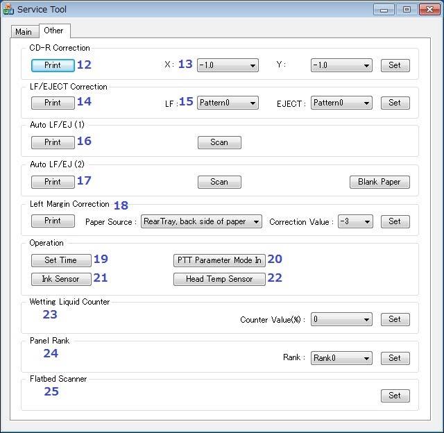
55 (2) Service Tool functions Service Tool screen: Version / 76
56 52 / 76
57 No. Name Function Remarks 1 Test Print Service test print Paper will feed from the rear tray (2 sheets). Printed items: - Model name - ROM version - USB serial number - Process inspection information - Barcode (model name + destination + machine serial number) - Ink system function check result - DVD / CD sensor check result (not applicable to the MX880 series) 2 EEPROM EEPROM information print The dialog box opens to select the paper source. Select Rear tray or Cassette, and click OK.. Printed items: - Model name - ROM version - Ink absorber counter value - Print information - Error information, etc. 3 Nozzle Check Nozzle check pattern print The dialog box opens to select the paper source. Select Rear tray or Cassette, and click OK. The same pattern as the one in the user mode is printed. 4 Integration Integrated inspection pattern print 5 Auto Cleaning Enabling / disabling of automatic print head cleaning Paper will feed from the rear tray (if the cassette is selected, the error is displayed). Multiple inspection items are printed just in one page, thus it is recommended to use this function for the standard inspection. Printed items: - Model name - ROM version - USB serial number - Nozzle check pattern (same as the one in the user mode) - Process inspection information - Barcode (machine serial number) - Ink system function check result - DVD / CD sensor check result (not applicable to the MX880 series) Automatic print head cleaning prior to printing (after replacement of an ink tank or the print head). Select this option to enable the cleaning. 6 Deep Cleaning Print head deep cleaning Cleaning of both Black and Color at the same time (same as the one in the user mode) 7 Main (Clear Ink Counter) Main ink absorber counter resetting Set a sheet of A4 or Letter sized plain paper. After the ink absorber counter is reset, the counter value is printed automatically. 53 / 76
58 Platen (Clear Ink Counter) Platen ink absorber counter resetting 8 EEPROM Save EEPROM information saving Not used. The EEPROM information (same as the one in EEPROM information print) is displayed on the PC or is saved to the PC as a text file. This function is not available in most cases of errors. 9 Panel Check Button and LCD test See "(4) Button and LCD test" below. 10 Set Destination Destination settings Select the destination, and click Set. ASA, AUS, BRA, CHN, CND, EMB, EUR, JPN, KOR, LTN, TWN, USA 11 Ink Absorber Counter 12 Print (CD-R Correction) Ink absorber counter setting See "(5) Ink absorber counter setting" below. Printing of the pattern for disc label print position correction 13 CD-R Correction Disc label print position correction (X and Y direction) 14 Print (LF/ EJECT Correction) 15 LF/ EJECT Correction LF / Eject correction pattern print LF / Eject correction value settings 16 Auto LF/EJ (1) Automatic LF / Eject correction 17 Auto LF/EJ (2) Automatic LF / Eject correction 18 Left Margin Correction Left margin pattern print and correction Not used. Not used. Perform LF / Eject correction only when streaks or uneven printing occurs after the repair. See "(3) LF / Eject correction" below. Set the correction value based on the printed pattern (14. LF/EJECT correction pattern print). See "(3) LF / Eject correction" below. Not used. Not used. Not used. 19 Set Time Time setting Not used. 20 PTT Parameter Mode In Entry in the PTT parameter mode 21 Ink Sensor Pressure sensor correction Not used. 22 Head Temp Sensor 23 Wetting Liquid Counter Print head diode sensor correction Wetting liquid counter setting 24 Panel Rank Capacitive sensor sensitivity setting 25 Flatbed Scanner Individual scanner adjustment Entry in the PTT parameter mode is allowed when this button is clicked. Not used. Not used. Not used. Not used. 54 / 76

59 (3) LF / Eject correction After replacement of the feed roller, platen unit, LF / Eject encoder, carriage encoder film, or logic board in repair servicing or in refurbishment operation, perform the adjustment to maintain the optimal print image quality. If the print quality is considered unaffected by replacement of those parts, it is not necessary to perform LF / Eject correction. 1) Print the LF / Eject correction pattern. Click Print in the LF/EJECT Correction section of the Service Tool, select the paper source and the paper type, and print the pattern. 5 sheets of A4 paper will be used for the pattern printing. - Paper source: Select either Rear tray or Cassette. - Media type: Select one from HR-101, GF-500/Office Planner, HP Bright White, and Canon Extra/STEINBEIS. 2) When printing is finished, the machine returns to be ready for selection of another function ("A function was finished" is displayed on the screen). 3) In the printout, determine the Pattern No. in which streaks or lines are the least noticeable for the LF check pattern and the Eject check pattern respectively. (LF Pattern No. 0 to 4, Eject Pattern No. 0 to 4) 4) Select and set the correction values. In the LF/EJECT Correction section of the Service Tool, select the Pattern No. (from 0 to 4) determined in step 3) for LF and EJECT respectively, and click Set. 5) The selected LF and Eject correction values are written to the EEPROM, making the E-MIP correction value (which was set at shipment from the production site) invalid. Note: At the production site, the E-MIP correction, which is equivalent to the LF / Eject correction, is performed using the special tool, and the E-MIP correction value is written to the EEPROM as the valid data. When LF / Eject correction is performed, the LF / Eject correction values become valid instead of the E-MIP correction value (thus, in the initial EEPROM information print, "LF = *" and "EJ = *" are printed, but the selected values are printed after the LF / Eject correction). 55 / 76
 Dual Function Panel check 1-1) Click Panel Check of the Service Tool.")
 Press the Black button.")
 Press the Black button again.")
60 (4) Button and LCD test Confirm the operation after replacement of the panel board or LCD. 1) Dual Function Panel check 1-1) Click Panel Check of the Service Tool. All the buttons of the Dual Function Panel turn on and the LCD is divided into 16 white segments by the red lines. 1-2) Press the Black button. The buttons that are valid in the copy mode appear on the panel, and the segments on the LCD corresponding to those buttons turn white while the other areas turn black. 1-3) Press the Black button again. The buttons that are valid in the FAX mode appear on the panel, and the segments on the LCD corresponding to those buttons turn white while the other areas turn black. 56 / 76
 Press each button of the operation panel, to see if every button functions properly. 2-3) The LCD is divided into 36 segments, representing each button.")

61 2) Button check 2-1) Press the Black button. All the LED's on the machine turn on and the LCD turns blue, waiting for a button to be pressed. 2-2) Press each button of the operation panel, to see if every button functions properly. 2-3) The LCD is divided into 36 segments, representing each button. The color of a segment corresponding to the pressed button changes to red. If 2 or more buttons are pressed at the same time, only one of them is considered to be pressed, and the other buttons are ignored. 1. ON 2. Stop 3. COPY 4. FAX 5. SCAN 6. CARD 7. Setup 8. Black 9. Color 10. Redial/Pause 11. Coded Dial 12. Hook 13. [+], up cursor Up cursor, [-], OK 18. Left cursor, OK, Right cursor, Back, down cursor Down cursor, Back 26. * # 29. Left function button 30. Center function button 31. Right function button 3) Scroll Wheel check 3-1) Press the Black button. The color pattern is displayed on the LCD. 3-2) Visually confirm that the patterns are displayed properly. 3-3) Press the ON button. The machine returns to be ready for another function in the service mode. 57 / 76
62 (5) Ink absorber counter setting Set the ink absorber counter value to a new EEPROM after the logic board is replaced in servicing. 1) Before replacement of the logic board, check the ink absorber counter value in EEPROM information print. 2) After replacement of the logic board, the ink absorber counter value should be set in the service mode using the Service Tool. In the Ink Absorber Counter section of the Service Tool, select Main from the Absorber pull-down menu. From the Counter Value(%) pull-down menu, select the value (in 10% increments) which is the closest to the actual counter value confirmed before replacement of the logic board, and click Set. 3) Print EEPROM information to confirm that the value is properly set to the EEPROM. <3-1. Adjustment> <3-2. Adjustment and Maintenance in User Mode> <3-3. Adjustment and Settings in Service Mode> 58 / 76
63 MX880 series ADJUSTMENT / SETTINGS TABLE OF CONTENTS 3-4. Adjustment and Maintenance in PTT Parameter Mode Enter the PTT parameter mode in the user mode as below. (The PTT parameter mode cannot be entered in the service mode.) 1) In the user mode, press the SCAN button to enter the scan mode. 2-a) Press #, 9, 7, 6, 9, # to enter the PTT parameter mode. 2-b) Press #, 9, 7, 6, 8, # to print the PTT parameter setting value. How to finalize the data: Press the OK button to finalize the data, then press the Stop button to save the data. How to exit the PTT parameter mode: Press the ON button to write the saved data to the EEPROM and turn off the machine. <PTT parameter mode operation procedures> 1. In the user mode, press the SCAN button to enter the scan mode and press #, 9, 7, 6, 9, #. 2. The following message is displayed on the LCD. PTT PRAMETER #1 BIT SWITCH BIT SWITCH menu 3. Each time the right or left cursor button is pressed, the menu is changed. PTT PRAMETER #2 NUMERIC PARAM. NUMERIC PARAM. menu PTT PRAMETER #3 FAX TYPE Note: Not used in servicing. PTT PRAMETER #4 NCU Note: Not used in servicing. PTT PRAMETER #5 PTT SPECIAL Note: Not used in servicing. PTT PRAMETER #6 FAX TEST Note: Not used in servicing. 4. Press the OK button when #BIT SWITCH or #2 NUMERIC PARAM. is displayed to enter either of those modes. 59 / 76
64 <#1 BIT SWITCH> 1. In the #1 BIT SWITCH menu, the following screen is displayed: PTT PRAMETER #1 BIT SWITCH SW# Each time the up or down cursor button (or the OK button) is pressed, the SW# changes from 01 to 20. Be cautious not to select the SW numbers which are not used in servicing. The SW numbers used in servicing: SW# 01, 02, 03, 04, 05, 06, 07, 10, 11, 13 The SW numbers not used in servicing (as of December 2007): SW# 08, 09, 12, 14 to Each SW# has 8-bit information. Using the left or right cursor buttons, move the cursor to the bit to be changed, and enter the setting value (1 or 0). Bit7 -> <- Bit0 4. Press the OK button to finalize the setting value. For the definition and description of each bit of each SW#, refer to the " G3 Facsimile Service Data Service Handbook." English: QY8-13BC-010 Japanese: QY8-12B Press the Stop button to save the setting value. 6. Press the ON button. <#2 NUMERIC PARAM.> 1. In the #2 NUMERIC PARAM. menu, the following screen is displayed: PTT PRAMETER #2 NUMERIC PARAM 01: Each time the up or down cursor button (or the OK button) is pressed, the SW# changes from 01 to 60. Be cautious not to select the SW numbers which are not used in servicing. The SW numbers used in servicing: SW# 01, 02, 04 to 09, 16 to 24, 26, 27, 30, 31, 41, 42 The SW numbers not used in servicing (as of December 2007): SW# 03, 10 to 15, 25, 28, 29, 32 to 40, 43 to Enter a desired setting value, using the right or left cursor button or numeric buttons. (Specifiable values vary depending on the item.) 4. Press the OK button to finalize the selected setting value. For the definition and description of each bit of the SW#, refer to the " G3 Facsimile Service Data Service Handbook." English: QY8-13BC-010 Japanese: QY8-12B Press the Stop button to save the setting value. 6. Press the ON button. 60 / 76
65 <Confirmation of the setting values> Print and confirm the PTT parameter setting values in the following procedures: 1) In the user mode, press the SCAN button, then press #, 9, 7, 6, 8, #. 2) The PTT parameter mode values are printed. For the definition and description of each bit of the SW#, refer to the "G3 Facsimile Service Data Service Handbook." English: QY8-13BC-010 Japanese: QY8-12B6-020 PTT parameter print sample for the MX883 Japan model: 61 / 76
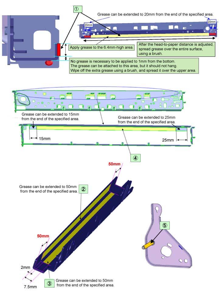
66 3-5. Grease Application No Part name Where to apply grease / oil Drawing No. Grease Grease amount (mg) Number of drops x Location 1 Carriage rail The surface where the carriage unit slides (1) Floil KG107A 230 to Carriage rail The surface where the carriage unit slides (2) Floil KG107A 180 to Carriage rail The surface where the carriage unit slides (3) Floil KG107A 180 to Main chassis The surface where the carriage unit slides (4) Floil KG107A 230 to APP code wheel gear shaft APP code wheel gear sliding portion (the entire surface) (5) Floil KG107A 9 to 18 1 x 1 1 drop = 9 to 18 mg 62 / 76
67 63 / 76
 Examine the ink tank conditions. - Is the outer film completely removed to open the air-through? - Re-install the ink tanks.")
68 3-6. Special Notes on Servicing (1) For smeared printing, uneven printing, or non-ejection of ink When smeared printing, uneven printing, or non-ejection of ink occurs, print the nozzle check pattern to determine whether the print head is faulty or not. < Procedures > 1) Examine the ink tank conditions. - Is the outer film completely removed to open the air-through? - Re-install the ink tanks. - Is the ink tank Canon-genuine or not? - Is the ink tank refilled one or not? 2) Remove and clean any foreign material from the caps of the purge unit. 3) Perform print head cleaning or deep cleaning. 4) Perform print head alignment. 5) Print the nozzle check pattern. 6) If the nozzle check pattern is not printed properly, the print head may be faulty. Perform troubleshooting while referring to the Print Head Workshop Manual or the Print Head Service Manual, 1-4. Troubleshooting. Manual name No. Form Price (JPY) Print Head Workshop Manual QY D0C CD-ROM 50,000 Print Head Service Manual QY D0C CD-ROM 30,000 (2) Paper feed motor adjustment 1) When attaching the motor, fasten the screws so that the belt is properly stretched (in the direction indicated by the blue arrow in the photo below). 2) After replacement, be sure to perform the service test print, and confirm that no strange noise or faulty print operation (due to dislocation of the belt or gear, or out-of-phase motor, etc.) occurs. The screws securing the paper feed motor may be loosened only at replacement of the paper feed motor unit. DO NOT loosen them in other cases. 64 / 76

69 (3) Carriage unit replacement In the MX880 series, the carriage rail needs to be removed from the main chassis. Before removing the screws from the carriage rail, put a mark on the main chassis to indicate the carriage rail position. After replacing the carriage, return the carriage rail to the original position while aligning the rail to the mark on the chassis. (4) Document pressure sheet (sponge sheet) replacement 1) Peel off the cover sheet from the double-sided adhesive tape on the back of the document pressure sheet. With the long-side down, position the upper-left corner of the document pressure sheet at the scanning reference point on the platen glass (back left where the red lines cross in the photo above). 2) Slowly close the document pressure plate, while maintaining the hinge position. The document pressure sheet will attach to the plate frame. 3) Open the plate to confirm the following: - No extension of the sponge edges over the mold part of the upper scanner cover. - No gap between the platen glass reference edges and the corresponding sponge edges. - No shades or streaks in monochrome test printing without a document on the platen glass. 65 / 76
 In addition, according to the \"Guideline for Preventive Replacement of Ink Absorber,\" replace the ink absorber. When the ink absorber is replaced, reset the applicable ink absorber counter (to 0%).")
70 (5) Ink absorber counter setting Before replacement of the logic board, check the ink absorber counter value, and register it to the replaced new logic board. (The value can be set in 10% increments.) In addition, according to the "Guideline for Preventive Replacement of Ink Absorber," replace the ink absorber. When the ink absorber is replaced, reset the applicable ink absorber counter (to 0%). See 3-3. Adjustment and Settings in Service Mode. (6) Preventive replacement of ink absorber Replace the ink absorber in accordance with the "Guideline for Preventive Replacement of Ink Absorber" even when the ink absorber is not full. (Related Service Information #Q-12E/J-0188) < Guideline for preventive replacement of ink absorber > Replace the ink absorber when it falls in either Criteria 1 or Criteria 2. Criteria Purpose How to know the criteria values Criteria 1: The ink absorber life * is 2 years or less. To avoid re-repair for ink absorber replacement in a short period of time after repair for other reasons. For H or earlier products: EEPROM information print and the quick reference table (Service Information #Q-12E/J-0188) For H and later products: EEPROM information print Criteria 2: The ink absorber counter value is 80% or more. To prevent ink leakage during return of the repaired printer to users. EEPROM information print * The estimated number of months until the ink absorber will become full < How to judge > Print the EEPROM information, and check the "D" (ink absorber counter) and "DF" (ink absorber life) values. Step 1: Is "D" 80% or more? Yes (80% or more) -> Replace the ink absorber. No (less than 80%) -> Proceed to Step 2. Step 2: Is "DF" 24 or more? No (less than 24 months) -> Replace the ink absorber. Yes (24 months or more) -> No need to replace the ink absorber. Note: - If the "ST" (installation date) value is 2010/06/30 or earlier, the "DF" (ink absorber life) value may not be correct. Skip Step 2 - The ink absorber life is an estimated value calculated based on the user's machine usage. < How to read the EEPROM information print > 66 / 76

 When the bottom case is replaced, be sure to remove the rating label from the original bottom case and attach it to the replaced")

71 (7) Power supply unit and modular board replacement 1) The ground wiring to the AC adapter differs between the Japan model and the other models. <Japan model> <Other models> Note: The photos are of the MX870 as an example. 2) The ground wiring to the modular board differs between the Japan model and the other models. <Japan model> <Other models> Note: The photos are of the MX870 as an example. (8) Rating label on the bottom case (except China*) When the bottom case is replaced, be sure to remove the rating label from the original bottom case and attach it to the replaced new one. The rating label is given to each printer unit respectively, thus the label of one unit is valid only for that unit. For this reason, the label is not available as a service part. * Note that there is no shipment of the bottom case to China.


72 (9) PTT label on the bottom case (for New Zealand only) When the bottom case is replaced, be sure to attach the PTT label from the original bottom case to the replaced new one. The PTT label is given to each printer unit respectively, thus the label of one unit is valid only for that unit. For this reason, the label is not available as a service part. (10) Speed Dial Utility Speed Dial Utility allows users to back up or edit the registered user data (coded speed dials, group dials, phone books, etc.) on a computer. Since those user data is considered as private information and requires a careful handling, we ask users to use this utility. The dialog box below is for the MX870 as an example. <3-4. Adjustment and Maintenance in PTT Parameter Mode> <3-5. Grease Application> <3-6. Special Notes on Servicing>
73 MX880 series TABLE OF CONTENTS 4. VERIFICATION AFTER REPAIR 4-1. Standard Inspection Flow In each step below, confirm that printing is performed properly and the machine operates properly without any strange noise. EEPROM information print <Check point> - The information must be printed properly. <Additional verification to be made> See 2-1. Major Replacement Parts and Adjustment. - At logic board replacement - At absorber kit replacement - At platen unit or spur unit replacement - At operation panel unit or LCD unit replacement - At wireless LAN board ass'y replacement Integrated inspection pattern print <Check point> - The pattern must be printed properly. Copy function <Check point> - Copying must be performed properly. <Additional verification to be made> See 2-1. Major Replacement Parts and Adjustment. - At document pressure sheet or scanner unit replacement Communication with a connected PC <Check point> - Via USB connection to the PC, printing from the PC must be performed properly (paper feeding from the rear tray and from the cassette respectively). <Additional verification to be made> - For repair of a specific problem, confirm the applicable specific function in the user mode. PictBridge, IrDA communication, wired / wireless LAN, Bluetooth communication, Scanto-Memory function, Card Direct printing PictBridge, IrDA Wired / Wireless LAN Bluetooth Scan-to-Memory Card Direct Power-off in the service mode <Check point> - The paper lifting plate must be in the raised position. External and internal appearance <Check point> - No grease, oil, or smearing on the timing slit strip film. - No lifting of the platen ink absorber. - No foreign material or dislocation of any part inside the printer. - No damage or scratches that will affect the functionality. Packaging <Check point> See 6. MACHINE TRANSPORTATION. - The carriage must be locked in the home position.

74 4-2. Integrated Inspection Pattern Print < Print sample >
75 4-3. Ink Absorber Counter Value Print <Print sample> <4. VERIFICATION AFTER REPAIR>
76 MX880 series TABLE OF CONTENTS 5. APPENDIX 5-1. Customer Maintenance Adjustment Timing Purpose Tool Automatic print head alignment Manual print head alignment Print head cleaning Print head deep cleaning Ink tank replacement Paper feed roller cleaning Bottom plate cleaning - At print head replacement - When print quality is not satisfying (uneven printing, etc.) - At print head replacement - When print quality is not satisfying (uneven printing, etc.) - When automatic print head alignment is not effective - When MP-101 is not available When print quality is not satisfying. When print quality is not satisfying, and not improved by print head cleaning. When an ink tank becomes empty. ("No ink error" displayed on the monitor or on the machine LCD, or short flashing of an ink tank LED) - When paper does not feed properly. - When the front side of the paper is smeared. When the back side of the paper is smeared. To ensure accurate dot placement. To ensure accurate dot placement. To improve nozzle conditions. To improve nozzle conditions. To replace the empty ink tank. To clean the paper feed rollers of the selected paper source (rear tray or cassette). To clean the platen ribs. (Feed the paper from the rear tray.) Exterior cleaning When necessary To clean the machine exterior, or to wipe off dusts. - 1 sheet of MP PC, printer driver - 3 sheets of A4 plain paper - PC, printer driver - PC, printer driver - PC, printer driver Approx. time 5 min. 10 min. 1 min. 2 min min. - 3 sheets of A4 plain paper - PC, printer driver - 1 sheet of A4 plain paper - PC, printer driver Soft, dry, and clean lint-free cloth. 2 min. 1 min. 1 min.
77 5-2. Special Tools 5-3. Sensors Name Tool No. Application Remarks FLOIL KG-107A QY To the carriage rail sliding portions. In common with other products on the market No. Sensor Function Possible problems detected by the sensor 1 DES sensor Detects paper ejection from the ADF. - Paper jam in the ADF 2 DS sensor Detects paper feeding from the ADF. - No paper in the ADF 3 ADF cover sensor Detects opening and closing of the document feeder cover. 4 Scanner open sensor Detects opening and closing of the scanning unit (cover). 5 PE sensor Detects the positions of the leading and trailing edges of paper. 6 ASF cam sensor Detects the position of the ASF cam (during paper feeding from the rear tray). 7 APP encoder sensor Detects the amount of rotation of the APP encoder. (Controls purging operation and paper feeding from the rear tray or from the cassette). 8 LF encoder sensor Detects the amount of rotation of the LF encoder. 9 Eject encoder sensor 10 Temperature & Ink amount sensor Detects rotation of the eject encoder, and controls paper feeding. Detects the temperature of the inside of the machine and the remaining ink amount. - Although the document feeder cover is closed, the machine indicates that the cover is open. - The carriage does not move to the center even when the scanning unit (cover) is opened. - No paper - Paper jam - ASF cam sensor error - Paper feed problem - APP sensor error - APP position error - LF position error - Uneven printing - LF position error - Uneven printing - Internal temperature error - Low-ink or out-of-ink warning 11 Ink sensor Detects the position of an ink tank. - Wrong position of an ink tank - An error indicating that multiple ink tanks of the same color are installed - No recognition of an ink tank 12 Carriage encoder sensor Detects the position of the carriage. 13 Valve cam sensor Detects the position of the purge valve cam. (Controls purging operation.) 14 Pump roller sensor Detects the position of the purge pump roller. (Controls purging operation.) 15 Purge cam sensor Detects the position of the purge main cam. (Controls purging operation.) - Carriage position error - Printing shifts from the correct position. - Uneven printing - Strange sound - Valve cam sensor error - Pump roller sensor error - Purge cam sensor error Click on the image to enlarge it.
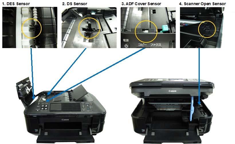
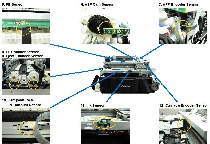
78

 is opened).")

79 5-4. Serial Number Location On the inner guide over the upper portion of the spur holder (visible when the scanning unit (cover) is opened). When the machine power is OFF. When the machine power is ON. Note: The photos are of the MX870 as an example. <5. APPENDIX>
PIXMA MP830 SERVICE MANUAL
 PIXMA MP830 SERVICE MANUAL Revision 0 QY8-3AN-000 COPYRIGHT 2006 CANON INC. CANON PIXMA MP830 022006 XX 0.00-0 Scope This manual has been issued by Canon Inc., to provide the service technicians of this
ip3600 / ip3680 SIMPLIFIED SERVICE MANUAL
 ip3600 / ip3680 SIMPLIFIED SERVICE MANUAL QY8-13BW-000 Rev. 00: August 2008 Canon Inc. (1/17) TABLE OF CONTENTS 1. LIST OF ERROR DISPLAY / TROUBLESHOOTING 1-1. Operator Call s (Alarm LED Lit In Orange)
QY8-13BN-000 COPYRIGHT 2007 CANON INC. CANON MP XX
 MP520 Service Manual Revision 0 QY8-13BN-000 Scope COPYRIGHT 2007 CANON INC. CANON MP520 072007 XX 0.00-0 This manual has been issued by Canon Inc., to provide the service technicians of this product with
PIXUS ip8600 PIXMA ip8500 SERVICE MANUAL
 PIXUS ip8600 PIXMA ip8500 SERVICE MANUAL Revision 0 QY8-13A5-000 COPYRIGHT 2004 CANON INC. CANON PIXUS ip8600/pixma ip8500 082004 XX 0.00-0 Scope This manual has been issued by Canon Inc., to provide the
MP240 / MP245 MP260 / MP268 MP480 / MP486 SIMPLIFIED SERVICE MANUAL
 MP240 / MP245 MP260 / MP268 MP480 / MP486 SIMPLIFIED SERVICE MANUAL QY8-13BV-000 Rev. 00: June 2008 Canon Inc. (1/13) TABLE OF CONTENTS 1. LIST OF ERROR DISPLAY / TROUBLESHOOTING 1-1. Operator Call Errors
MP640 MP648 QY8-31DR-000 COPYRIGHT 2009 CANON INC. CANON MP648/MP N REVISION 0
 MP640 MP648 REVISION 0 3748B001AA MP640 / 100V(JP) 3748B002AA MP640 / 120V(US) 3748B003AA MP640 / 120V(CA) 3748B008AA MP640 / 220V-240V(EMB) 3748B009AA MP640 / 220V-240V(GB) 3748B011AA MP640 / 220V-240V(AU)
MP630 MP638 QY8-31DE-000 COPYRIGHT 2008 CANON INC. CANON MP638/MP N REVISION 0
 MP630 MP638 REVISION 0 2920B001AA MP630 / 100V(JP) 2920B003AA MP630 / 120V(CA) 2920B006AA MP630 / 220V-240V(EUM) 2920B007AA MP630 / 220V-240V(EMB) 2920B008AA MP630 / 220V-240V(GB) 2920B011AA MP630 / 220V-240V(AU)
i70 SERVICE MANUAL Canon
 i70 SERVICE MANUAL Canon PIXUS 50i i70 SERVICE MANUAL Revision 0 QY8-1388-000 COPYRIGHT 2003 CANON INC. CANON PIXUS 50i / i70 102001 XX 0.00-0 PRINTED IN JAPAN (IMPRIME AU JAPON) Scope This manual has
MX920 series. Online Manual. Troubleshooting. English
 MX920 series Online Manual Troubleshooting English Troubleshooting The Machine Cannot Be Powered On Printing Does Not Start Paper Does Not Feed Properly/"No Paper" Error Occurs Print Results Not Satisfactory
Product Parts Front view... 2 Rear view... 2 Inside the product... 3 Scanner parts... 3 Control panel... 4
 Table of Contents Product Parts Front view................................................................. 2 Rear view.................................................................. 2 Inside the product...........................................................
PIXUS ip90 PIXMA ip90
 PIXUS ip90 PIXMA ip90 REVISION 0 9644A001AA 9644A002AA 9644A003AA 9644A005AA 9644A008AA 9644A009AA 9644A010AA 9644A011AA 9644A012AA 9644A013AA 9644A014AA 9644A015AA 9644A017AA PIXMA ip90/ 120V(US) PIXMA
4.8. Other Errors Image system problem
 4.8. Other Errors 4.8.1. Image system problem No Problem Description Troubleshooting Page 1 Toner cartridge detection error P.4 242 2 Image registration problem occurs after ACR (Auto Color Registration)
4.7. Image quality problems and solutions
 4.7. Image quality problems and solutions Print-quality defects can be attributed to printer components, consumables, media, internal software, external software applications and environmental conditions.
TOSHIBA Potable Printer B-EP4DL SERIES. Maintenance Manual. Document No. EO Original Sep., 2008 (Revised ) PRINTED IN JAPAN
 PRINTED IN JAPAN") TOSHIBA Potable Printer B-EP4DL SERIES Maintenance Manual Original Sep., 2008 (Revised ) Document No. EO18-33023 PRINTED IN JAPAN WARNING! Follow all manual instructions. Failure to do so could create
TOSHIBA Potable Printer B-EP4DL SERIES Maintenance Manual Original Sep., 2008 (Revised ) Document No. EO18-33023 PRINTED IN JAPAN WARNING! Follow all manual instructions. Failure to do so could create
SERVICE MANUAL MODEL: MFC-8220
 SERVICE MANUAL MODEL: MFC-8220 Read this manual thoroughly before maintenance work. Keep this manual in a convenient place for quick and easy reference at all times. MFC-8220 SERVICE MANUAL PREFACE This
Removal and Installation8
 8 Screw Types 8-4 Top Cover Assembly 8-5 Left Hand Cover 8-6 Right Hand Cover 8-10 Front Panel Assembly 8-14 Left Rear Cover 8-15 Right Rear Cover 8-16 Extension Cover (60" Model only) 8-17 Media Lever
Getting Started. Read Me First. series. Canon Inkjet Premium Photo Printer. 1 Preparation...P.1. Install the Print Head... P.3
 Canon Inkjet Premium Photo Printer series 1 Preparation...P.1 Getting Started Read Me First Symbols Used in This Document Prohibited actions. Instructions including important information. In this guide,
Datacard CR500 Instant Issuance System. User Reference Guide. July Rev B
 Datacard CR500 Instant Issuance System User Reference Guide July 2015 527495-001 Rev B Datacard CR500 User Reference Guide The CR500 Instant Issuance System Contents The CR500 Instant Issuance System The
Updated 10/24/16 DAW
 Xerox WorkCentre 3215/3225 Service Manual Updated 10/24/16 DAW 702P02832 Main PL 1.1 Main... 5-3 ADF PL 1.2 ADF... 5-4 Covers PL 2.1 Covers... 5-5 Middle Cover PL 2.2 Middle Cover... 5-6 Frame PL 4.1 Frame...
ipf610 SERVICE MANUAL DU OCTOBER 2007 REV. 0 fineline6 CANON imageprograf 610 REV. 0 PRINTED IN U.S.A.
 ipf60 SERVICE MANUAL DU7-243-000 OCTOBER 2007 REV. 0 COPYRIGHT 2007 CANON INC. CANON imageprograf 60 REV. 0 PRINTED IN U.S.A. Conten Contents Chapter PRODUCT DESCRIPTION. Product Overview..... Product
September 18, 2012 Revision 0. Super G3 3rd/4th Line FAX Board-AE1 Service Manual
 September 18, 2012 Revision 0 Super G3 3rd/4th Line FAX Board-AE1 Service Manual 1 2 3 4 5 6 Application This manual has been issued by Canon Inc. for qualified persons to learn technical theory, installation,
LASERJET ENTERPRISE M604, M605, M606
 LASERJET ENTERPRISE M604, M605, M606 Maintenance kit replacement manual M604n M604dn M605x M605n M605dn M606x M606dn Conventions used in this guide TIP: Tips provide helpful hints or shortcuts. NOTE: Notes
SERVICE MANUAL. Super G3 Fax Board-AU1. Super G3 2nd Line Fax Board-AU1. October 14, 2016 Rev. 1
 Super G3 Fax Board-AU1 Super G3 2nd Line Fax Board-AU1 SERVICE MANUAL October 14, 2016 Rev. 1 COPYRIGHT 2016 CANON INC. CANON Super G3 Fax Board-AU1 / 2nd Line Fax Board-AU1 Rev. 1 PRINTED IN U.S.A. Introduction
K Service Source. StyleWriter
 K Service Source StyleWriter K Service Source Basics StyleWriter Basics Introduction - 1 Introduction The StyleWriter is a serial bubble jet ink-on-demand printer. The StyleWriter prints up to 1/3 page
fineline Service Manual ir2020/2016 Series
 Service Manual ir2020/2016 Series Jan 30 2006 Chapter 1 Introduction 1.1 System Construction...1-1 1.1.1 Pickup/ Delivery /Original Handling Accessories System Configuration (ir2020/ir2020j)...1-1 1.1.2
5 Parts List. Parts Lists 8570MFP Covers PL MFP Covers Covers PL Covers Imaging PL 2.0 Imaging...
 Overview... 5-3 Serial Number Format... 5-3 s 8570MFP Covers PL 1.0 8860MFP Covers... 5-4 8570 Covers PL 1.1 8860 Covers... 5-5 Imaging PL 2.0 Imaging... 5-6 8570MFP Paper Path PL 3.0 8860MFP Paper Path...
Océ User manual. Océ CS2024. Quick Start Guide
 Océ User manual Océ CS2024 Quick Start Guide Océ Technologies B.V. Copyright 2005, Océ-Technologies B.V. Venlo, The Netherlands. All rights reserved. No part of this work may be reproduced, copied, adapted,
Cutter Option Installation Instructions
 This kit includes the parts and documentation necessary to install the cutter option on the Zebra XiII, XiIII, and XiIIIPlus-Series printers. NOTE: The Cutter Option is not available for the 96XiIII. Adding
HP Color LaserJet CM2320 MFP Series Service Manual
 HP Color LaserJet CM2320 MFP Series Service Manual Table of contents 1 Product basics Quick access to product information... 2 Product comparison... 3 Product features... 4 Product walkaround... 5 Front
Troubleshooting Guide imagerunner ADVANCE C5560 Series
 Troubleshooting Guide imagerunner ADVANCE C5560 Series April, 2017 OIP Field Quality Assurance Div. New Arrival Information [Regarding Troubleshooting Guide] Please be advised of the release of Troubleshooting
Getting Started. Read Me First. series. Photo Printer
 Photo Printer series Getting Started Read Me First Make sure to read this manual before using the printer. Please keep it in hand for future reference. Symbols Used in This Document Instructions including
SERVICE MANUAL. Color Inkjet Printer
 SERVICE MANUAL Color Inkjet Printer Epson WF-755 / Epson WF-75 / Epson WF-750/ Epson WF-755 / Epson WF-75 / Epson WF-750/ Epson WF-708 / Epson WF-705 / Epson WF-70/ Epson WF-70 / Epson WF-700 SEMF0-0 Notice:
WorkForce Pro WP-4090 User's Guide
 WorkForce Pro WP-4090 User's Guide Contents WorkForce Pro WP-4090 User's Guide... 9 Product Basics... 10 Printer Parts Locations... 10 Printer Parts - Top... 11 Printer Parts - Back... 12 Printer Parts
M7 SERIES Thermal Printer Service Manual 4. PART LIST. 4.1 Main Printer Assemblies
 4. PART LIST 4.1 Main Printer Assemblies 31 No. Part No. Description Remark Spare Requirement 1 120732 Electronics cover 1 pc 2 N/A Mainframe 1 pc 3 120733 Cover, front 1 pc 4 120734 Top right side cover
HP Deskjet F2100 All-in-One series. Basics Guide
 HP Deskjet F2100 All-in-One series Basics Guide Hewlett-Packard Company notices The information contained in this document is subject to change without notice. All rights reserved. Reproduction, adaptation,
ET User's Guide
 ET-16500 User's Guide Contents ET-16500 User's Guide... 13 Your Ink Tank System... 14 Product Basics... 15 Using the Control Panel... 15 Control Panel Buttons and Lights... 16 Status Icons... 17 Status
MX-8000 User Manual MX Rev
 MX-8000 Rev. 070202 Greeting Thank you for purchasing PAITEC USA products. This manual is prepared to provide guidelines on how to properly operate and maintain MX-8000. Copyright Any of the contents should
Photo Printer. Direct Printing Guide
 Photo Printer Direct Printing Guide Contents Contents Operation Panel Names and Functions Operation Panel.................................................................... 3 Icons on the LCD....................................................................
SERVICE MANUAL THEORY OF OPERATION MB Ver. 1.0
 SERVICE MANUAL THEORY OF OPERATION 2005.04 Ver. 1.0 After publication of this service manual, the parts and mechanism may be subject to change for improvement of their performance. Therefore, the descriptions
WF-6530 User's Guide
 WF-6530 User's Guide Contents WF-6530 User's Guide... 15 Product Basics... 16 Using the Control Panel... 16 Control Panel Buttons and Lights... 17 Status Icon Information... 18 Status Button Information...
K Service Source. Color StyleWriter 2200
 K Service Source Color StyleWriter 2200 K Service Source Basics Color StyleWriter 2200 Basics Overview - 1 Overview The Color StyleWriter 2200 is a desktop color bubblejet printer for personal use. It
ipf5100 SERVICE MANUAL DU AUGUST 2007 REV. 0 fineline6
 ipf5100 SERVICE MANUAL DU7-1234-000 AUGUST 2007 REV. 0 COPYRIGHT 2006 CANON INC. CANON imageprograf ipf5100 REV. 0 PRINTED IN U.S.A. Conten Chapter 1 PRODUCT DESCRIPTION 1.1 Product Overview... 1-1 1.1.1
Replacing the Encoder Strip
 6-1-11. Replacing the Encoder Strip The following describes the procedure for replacing the Encoder Strip. Refer to the diagram below for identifying the parts and their positions. (The numbers shown in
Troubleshooting Guide
 MULTIFUNCTIONAL DIGITAL COLOR SYSTEMS Troubleshooting Guide ES9465 MFP/ES9475 MFP 03 Oki Data Corporation All rights reserved Under the copyright laws, this manual cannot be reproduced in any form without
fi-4120c Image Scanner
 P3PC-E007-01EN fi-4120c Image Scanner Cleaning and Maintenance 5 DAILY CARE This chapter describes how to clean the scanner. WARNING When cleaning the scanner, turn off the power, and unplug the AC cable
Setup Guide. Confirming the Installation Space. Installation space (W x D x H) 70.5 x 66.3 x 61.5 inches (1790 x 1684 x 1560 mm) 23.
 70.5 x 66.3 x 61.5 inches (1790 x 1684 x 1560 mm) 23.") Introductory Information Setup Guide ENGLISH Read this manual before attempting to operate the printer. Keep this manual in a handy location for future reference. Caution Instructions in this Setup Guide
Introductory Information Setup Guide ENGLISH Read this manual before attempting to operate the printer. Keep this manual in a handy location for future reference. Caution Instructions in this Setup Guide
WF-5690 User's Guide
 WF-5690 User's Guide Contents WF-5690 User's Guide... 15 Product Basics... 16 Using the Control Panel... 16 Control Panel Buttons and Lights... 17 Status Icon Information... 18 Status Button Information...
MC-2548-V1.00. Troubleshooting. Advanced Guide. Basic Guide. Describes the summary of this product. Describes the detailed function of this product.
 ip1900 series On-screen Manual Стр. 1 из 334 стр. How to Use This Manual Printing This Manual MC-2548-V1.00 Basic Guide Describes the summary of this product. Advanced Guide Describes the detailed function
Field Replaceable Units (FRU) Parts List
 Parts List") Field Replaceable Units (FRU) Parts List This chapter provides a list of field replaceable units (FRU s) for the printer. Changes to Xerox parts are made to accommodate improved components as they become
Field Replaceable Units (FRU) Parts List This chapter provides a list of field replaceable units (FRU s) for the printer. Changes to Xerox parts are made to accommodate improved components as they become
www MK-Electronic de 5 Parts List 5 Parts List Parts List Overview Serial Number Format
 Overview... 5-3 Serial Number Format... 5-3 5 PL 1.1Covers... 5-4 PL 2.1 Imaging... 5-5 PL 3.1 Paper Path... 5-6 PL 4.1 Drive... 5-7 PL 5.1 Electrical... 5-8 PL 6.1 Sensors and Actuators... 5-9 Xerox Supplies
ip3600 series Getting Started =Read Me First= Photo Printer
 Photo Printer ip3600 series Getting Started =Read Me First= Make sure to read this manual before using the printer. Please keep it in hand for future reference. Symbols The following symbols are used to
Quick Start Guide. Chapter 1 : Setting the Machine. Unpack the machine and its components. Check that you have the following: Machine
 Quick Start Guide READ THIS FIRST Thank you for purchasing Canon Color imageclass MF8180c. To get your machine ready for use, please follow the instructions in this document before referring to any other
SERVICE MANUAL THEORY OF OPERATION AD Ver. 1.0
 SERVICE MANUAL THEORY OF OPERATION 2005.04 Ver. 1.0 After publication of this service manual, the parts and mechanism may be subject to change for improvement of their performance. Therefore, the descriptions
Installing the Printer Software
 4 Printing Your First Page Attaching the Paper Support 7 1 Checking the Printer 6 2 Plugging in the Printer 3 Installing the Ink Cartridges 5 Installing the Printer Software Connecting the Printer 4012581-00
MC-2984-V1.00. Troubleshooting. Advanced Guide. Basic Guide. Describes the summary of this product. Describes the detailed function of this product.
 ip4600 series On-screen Manual Стр. 1 из 396 стр. How to Use This Manual Printing This Manual MC-2984-V1.00 Basic Guide Describes the summary of this product. Advanced Guide Describes the detailed function
CopyCentr C118. M118/M118i. copy print fax . Service. Manual
 CopyCentr C118 M118/M118i copy print fax email Service Manual About this Manual... Organization... How to Use this Documentation... Symbology and Nomenclature... Translated Warnings... iii iii iv v viii
Contents XP-830 User's Guide Product Basics Wi-Fi or Wired Networking... 38
 XP-830 User's Guide Contents XP-830 User's Guide... 15 Product Basics... 16 Using the Control Panel... 16 Control Panel Buttons and Lights... 17 Using the LCD Screen... 18 Adjusting Control Panel Position...
WF-R4640 User's Guide
 WF-R4640 User's Guide Contents WF-R4640 User's Guide... 15 Product Basics... 16 Using the Control Panel... 16 Control Panel Buttons and Lights... 17 Status Icon Information... 18 Status Button Information...
Lexmark X642 Troubleshooting Guide
 Lexmark X642 Troubleshooting Guide Online technical support Technical support is available on our Lexmark Web site at www.lexmark.com. Checking an unresponsive printer If the printer is not responding,
HP Deskjet 1510 series
 HP Deskjet 1510 series Table of contents 1 HP Deskjet 1510 series Help... 1 2 Get to know the HP Deskjet 1510 series... 3 Printer parts... 4 Control panel features... 5 Status light... 6 Auto-Off... 9
SERVICE MANUAL THEORY OF OPERATION DF Ver. 1.0
 SERVICE MANUAL THEORY OF OPERATION 2005.04 Ver. 1.0 After publication of this service manual, the parts and mechanism may be subject to change for improvement of their performance. Therefore, the descriptions
WorkForce WF-7510/WF-7520 User's Guide
 WorkForce WF-7510/WF-7520 User's Guide Contents WorkForce WF-7510/WF-7520 User's Guide... 13 Product Basics... 14 Setting Up the Control Panel... 14 Control Panel Buttons and Lights... 14 Adjusting Control
Reference Guide Brief explanations for routine operations
 Reference Guide Brief explanations for routine operations MFC-J995DW Brother recommends keeping this guide next to your Brother machine for quick reference. Online User's Guide For more advanced instructions,
Color Bubble Jet Printer. Quick Start Guide
 Color Bubble Jet Printer Quick Start Guide Canon i350/i250 Color Bubble Jet Printer Quick Start Guide. Copyright This manual is copyrighted by Canon U.S.A., Inc. with all rights reserved. Under the copyright
Getting Started. Read Me First. series. Photo Printer
 Photo Printer series Getting Started Read Me First Make sure to read this manual before using the printer. Please keep it in hand for future reference. Contents 1 Preparation 2 Turn the Power On 3 Install
Before you can use the machine, you must set up the hardware. Please read this Quick Setup Guide for the correct setup procedure.
 FAX-2480C Quick Setup Guide Before you can use the machine, you must set up the hardware. Please read this Quick Setup Guide for the correct setup procedure. Setting Up the Machine Setup is Complete! Keep
MVPplus Quick Reference Guide
 MVPplus Quick Reference Guide Use this guide to operate your printer on a daily basis. For more detailed information, refer to the User Guide. Contents External View...........................................................
MULTIFUNCTIONAL DIGITAL COLOR SYSTEMS. Troubleshooting Guide
 MULTIFUNCTIONAL DIGITAL COLOR SYSTEMS Troubleshooting Guide 03-05 TOSHIBA TEC CORPORATION All rights reserved Under the copyright laws, this manual cannot be reproduced in any form without prior written
THE HP LASERJET M5025 / M5035 TONER CARTRIDGE
 THE HP LASERJET M5025 / M5035 TONER CARTRIDGE DOC# 0384 By Mike Josiah and the Technical Staff at Summit Technologies HP LJ M5025 / M5035 TONER CARTRIDGE REMANUFACTURING INSTRUCTIONS Page 1 Remanufacturing
Control-panel message types
 Control-panel message types Four types of control-panel messages can indicate the status of or problems with the product. Message type Status messages Warning messages Error messages Description Status
Troubleshooting Guide
 MULTIFUNCTIONAL DIGITAL COLOR SYSTEMS Troubleshooting Guide ES9455 MFP 03 Oki Data Corporation All rights reserved Under the copyright laws, this manual cannot be reproduced in any form without prior written
MULTIFUNCTIONAL DIGITAL COLOR SYSTEMS. Troubleshooting Guide
 MULTIFUNCTIONAL DIGITAL COLOR SYSTEMS Troubleshooting Guide 2008, 2009 TOSHIBA TEC CORPORATION All rights reserved Under the copyright laws, this manual cannot be reproduced in any form without prior written
Canon ir1600 / ir2000. Details
 E000 E001 E002 E003 E004 Error Codes Canon ir1600 / ir2000 Details The main thermistor reading does not reach 40 o C 14 sec after the fixing heater goes ON (fixing low temperature error) The main thermistor
ColorQube 8570/8870 Printer. Service Manual. Xerox Internal-Use Only
 ColorQube 8570/8870 Printer ColorQube 8570/8870 Service Manual Xerox Internal-Use Only About This Manual... Organization... How to Use this Manual... Power Safety... Service Safety Summary... Moving the
Removal and Installation 8
 Removal and Installation 8 8 Introduction 8-2 Service Calibration Guide to Removal and Installation 8-4 Window 8-8 Covers and Trims 8-12 Rear Tray 8-31 Rear Cover 8-32 Media Lever 8-33 Media Lever Position
Calibration and Maintenance
 Epson DX5 X 1 Printhead Calibration and Maintenance 31 st Jan., 2013 Version V3.0 1 Contents Chapter 1: Computer Requirement...3 Chapter 2:Installation...4 Chapter 3:Characteristic...5 Chapter 4:Board
4.1 General. 4 Replacement Procedures
 4.1 General This chapter explains how to disassemble the computer and replace Field Replaceable Units (FRUs). It may not be necessary to remove all the FRUs in order to replace one. The chart below is
Contents L4160 User's Guide Product Basics Wi-Fi Networking... 30
 L4160 User's Guide Contents L4160 User's Guide... 11 Product Basics... 12 Using the Control Panel... 12 Control Panel Buttons and Lights... 13 Status Icon Information... 13 Entering Characters on the
Legal Notes. Regarding Trademarks KYOCERA Document Solutions Inc.
 Legal Notes Unauthorized reproduction of all or part of this guide is prohibited. The information in this guide is subject to change without notice. We cannot be held liable for any problems arising from
LASERJET ENTERPRISE MFP M630
 LASERJET ENTERPRISE MFP M630 Maintenance kit replacement manual M630dn M630f M630z M630h Copyright and License 2014 Copyright Hewlett-Packard Development Company, L.P. Reproduction, adaptation, or translation
Quick Start Guide BUBBLE JET PRINTER. Table of Contents QA V01. Preface 1. Shipping Materials 1. Introduction 1.
 BUBBLE JET PRINTER Quick Start Guide Table of Contents Preface 1 Shipping Materials 1 Introduction 1 Setting Up 2 Preparing the Printer 2 Installing the Print Head 3 Connecting the Printer to the Computer
ET-4750 User's Guide
 ET-4750 User's Guide Contents ET-4750 User's Guide... 13 Product Basics... 14 Using the Control Panel... 14 Control Panel Buttons and Lights... 15 Status Icon Information... 15 Entering Characters on
Interpret control-panel messages
 Interpret control-panel messages Control-panel message types Four types of control-panel messages can indicate the status of or problems with the product. Message type Status messages Warning messages
MULTIFUNCTIONAL DIGITAL COLOR SYSTEMS. Troubleshooting Guide
 MULTIFUNCTIONAL DIGITAL COLOR SYSTEMS Troubleshooting Guide 0-05 TOSHIBA TEC CORPORATION All rights reserved Under the copyright laws, this manual cannot be reproduced in any form without prior written
1 HP Ersatzteile für DesignJet 500
 HP Ersatzteile für DesignJet 500 Back Platen and Media Sensor C7769-6040 C7770-6055* C7769-6068* Back platen assembly - Curved cover/guide that is installed below the paper drive roller (4-inches) Back
7 Troubleshooting. Chapter contents
 7 Troubleshooting Chapter contents Introduction.......................................... 205 Troubleshooting process................................ 206 Pre-troubleshooting checklist.........................
Downloaded from WF-3520/WF-3530 User's Guide
 WF-3520/WF-3530 User's Guide Contents WF-3520/WF-3530 User's Guide... 13 Product Basics... 14 Setting Up the Control Panel... 14 Control Panel Buttons and Lights... 14 Changing LCD Screen Language...
Getting Started. =Read Me First= series. Office All-In-One
 Office All-In-One series Getting Started =Read Me First= Make sure to read this manual before using the machine. Please keep it in hand for future reference. Contents 1 2 3 4 5 6 7 8 Preparation Remove
Understanding printer messages
 Understanding printer s Printer s that appear on the control-panel display relay the normal status of the printer (such as Processing...) or an error condition (such as CLOSE TOP COVER) that needs attention.
RJ-2030/2050/2140/2150
 Printed in China LBF85400 Package Contents Check that the package contains the following before using your printer: RJ-030/050/40/50 Quick Setup Guide English Printer Rechargeable Li-ion Battery Belt Clip
hp photosmart 7150 basics guide
 hp photosmart 7150 basics guide control panel The following table is a quick reference guide to the buttons that appear on your printer s control panel. CANCEL RESUME POWER contents 1 get started.........................................
WF-R5690 User's Guide
 WF-R5690 User's Guide Contents WF-R5690 User's Guide... 15 Product Basics... 16 Using the Control Panel... 16 Control Panel Buttons and Lights... 17 Status Icon Information... 18 Status Button Information...
www MK-Electronic de Business InkJet 3000dtn HP Parts Reference Guide Cables Chassis Parts Electronic Accessories Electronics/Power Supply Cable Base
 Cables Cable 1 C8116-67037 Power supply harness 2 C8116-67042 Trailing cable - Connects from the carriage PC board to the main logic PC board Chassis Parts Base 3 C8116-67001 Base assembly - Main frame
1 HP Ersatzteile für DesignJet 800
 HP Ersatzteile für DesignJet 800 Stand Assembly C7769-6040 C7770-6055* C7769-6068* Back platen assembly - Curved cover/guide that is installed below the paper drive roller (4-inches) Back platen assembly
Product End-of-Life Disassembly Instructions
 Product End-of-Life Disassembly Instructions Product Category: Scanners Marketing Name / Model [List multiple models if applicable.] Name / Model #1 HP ScanJet Pro 2500 f1 Name / Model #2 Name / Model
Troubleshooting with the control panel
 Troubleshooting with the control panel The tables in this section explain common messages that might appear on the control-panel display. Within each table, the messages and their meanings are listed in
Contents L575 User's Guide Your Ink Tank System Product Basics Wi-Fi or Wired Networking... 33
 L575 User's Guide Contents L575 User's Guide... 13 Your Ink Tank System... 14 Product Basics... 15 Using the Control Panel... 15 Control Panel Buttons and Lights... 15 Status Icons... 16 Entering Characters
ET-3700 User's Guide
 ET-3700 User's Guide Contents ET-3700 User's Guide... 11 Product Basics... 12 Using the Control Panel... 12 Control Panel Buttons and Lights... 13 Status Icon Information... 14 Entering Characters on
User s Manual. Troubleshooting Guide
 User s Manual Troubleshooting Guide This manual supports the following models. MC0x, MC0x, MC80x, ES0x MFP, ES80x MFP, MPSmc, MPSmc The illustrations of the machine used in this document may be different
User Guide. What You Can Do with This Machine. Getting Started. Copy. Fax. Print. Scan. Document Server. Web Image Monitor. Adding Paper and Toner
 User Guide What You Can Do with This Machine Getting Started Copy Fax Print Scan Document Server Web Image Monitor Adding Paper and Toner Troubleshooting Information for This Machine For safe and correct