VCSII Battery Charger Bergey WindPower Co. Owner s Manual
|
|
|
- Evangeline Fletcher
- 6 years ago
- Views:
Transcription


1 VCSII Battery Charger Bergey WindPower Co. Owner s Manual Rev: 1 June 17, 2016
2 Table of Contents Important Safety Instructions... 3 VCS II Mounting... 4 VCS II User Interface... 6 VCS II User Configuration... 7 VCS II Can Bus Interface VCS II CAN Bus Message Specification VCS II Status, Faults, & Warnings VCS II Fault List VCS II Warning List VCS II Specifications Turbine Input Battery Output Environmental Performance Rev: 1 June 17, 2016


3 Important Safety Instructions This manual contains important information concerning the installation of your VCSII. We strongly recommend that you read and familiarize yourself with its contents. At several points in this manual, items of special interest or significant impact are highlighted by one of the following symbols: DANGER: Hazard or unsafe practice that could cause personal injury or death. WARNING: Hazard or unsafe practice which could cause product damage. SAVE THESE INSTRUCTIONS This manual contains important instructions for the VCSII that shall be followed during installation and maintenance of the converter. The output field wiring terminal (Battery) can be used for connection of a maximum of: One 350MCM wire per terminal (1 wire for each line) The input field wiring terminal (Turbine) can be used for connection of a maximum of: One 2 AWG wire per terminal (1 wire per phase per terminal provided). The field-wiring terminals shall be connected using the following wire types: Copper Conductors Only (Input Turbine connection) Use No. 8-2 AWG, 75 C copper wire only Copper Conductors Only (Output Battery connection) Use No MCM, 75 C copper wire only The following symbols are used as markings on this product with the following meanings: Equipment grounding conductor This converter is intended for operation in an indoor NEMA 1 compatible environment having a maximum ambient temperature of 40 C (104 F). CAUTION To reduce the risk of fire, connect only to a circuit provided with 200 amperes maximum branch-circuit over-current protection in accordance with the National Electrical Code, ANSI/NFPA 70. Hot surfaces To reduce the risk of burns Do not touch The enclosure and the rear heatsink can exceed 70 C (150 F). Note that the input and output circuits are isolated from the enclosure. In accordance with Clause of CAN/CSA-C22.2 No , system grounding, when required by the Canadian Electrical Code, Part I, is the responsibility of the installer. Rev: 0 June 17,

4 VCS II Mounting WARNING: Confirm factory default settings are appropriate for you battery bank prior to commissioning to avoid potential battery damage. See the VCS II User Configuration section. The internal portion of the enclosure is sealed with no need for ventilation. The heatsinks, breaker and external inductors are re not sealed to the enclosure and results in a NEMA 1 rating. The bottom and top of the enclosure needs at least 12 of clearance to allow for natural convection through the rear heatsinks and inductors. Mount the enclosure indoors away from excess heat, vibration and moisture, and as close to the battery bank as possible. The mounting bracket must be secured to the wall before mounting the enclosure. The hardware to mount the bracket is not included. There are three main mounting holes at the top of the bracket on 16 centers and two holes at the bottom of the bracket. There are also 10 additional mounting holes at the top that can be used if necessary. Make certain that the combined mounting screws used are capable of holding the weight of 110 lb. (50 kg). Rev: 0 June 17,

5 DANGER: The unit is heavy. Use appropriate lifting methods. WARNING: Care must be used when lifting the enclosure to the mounting bracket to avoid any contact with the inductors to prevent their damage. To install the VCSII enclosure on the bracket, partially put the two top screws (M6x20) on both sides of the enclosure. They will be used to hang the unit on the bracket. Carefully lift the enclosure placing close attention to the rear magnetics so they are not damaged. Once the enclosure is hung, the bottom two mounting bolts can be installed and all tightened (Torque to 4.5N-m, 40in-lb). Conduit enters the bottom of the enclosure through provided knockouts. Drilling extra holes into the enclosure is not recommended. The turbine leads enter on the left side of the enclosure, while the battery connections are on the right side. WARNING: Clearance is required all sides of the enclosure for proper cooling. Clearance is required on all sides of the VCSII to ensure proper cooling by natural convection. Each side of the enclosure requires at least 6 inches (150mm) of clearance and the top and bottom of the enclosure requires a minimum of 12inches (300mm) to ensure a free flow of air through the rear mounted heatsinks. The VCS II does not use nor require fans for cooling for normal operation. The door is hinged on the bottom - ensure that there are no obstructions to the door opening. Rev: 0 June 17,
6 VCS II User Interface The charge controller user/operator control input interface consists of a single push button on the front panel of the charge controller. The single push button performs different functions depending on the controller system state and operating mode and the length of time that the button is pressed. The user push button functions are defined as follows: 1) No press of the user push button: a) If the charge controller is powered up and there are no faults, the charge controller will automatically go to the Charging Mode. The charge controller will charge the batteries, and then maintain the battery voltage at a specified float voltage. 2) Press and hold the user push button for more than 0.5 seconds and less than 5 seconds: a) If the charge controller is powered up and in the Charging Mode with no faults, the charge controller will go to the Manual Idle Mode. b) If the charge controller is powered up and in the Manual Idle Mode with no faults, the charge controller will go to the Charging Mode. c) If the charge controller is powered up and in a Fault State, the charge controller will clear the faults and go to the Charging Mode. d) If the charge controller is powered up and in the Equalize Mode with no faults, the charge controller will exit Equalize Mode and go to the Charging Mode. 3) Press and hold the user push button for more than 5 seconds: a) If the charge controller is powered up and in the Charging Mode with no faults, the charge controller will go to the Equalize Mode for a predetermined time period. After Equalization, the charge controller will go to normal charging mode, and will maintain the battery voltage at a specified float voltage. Rev: 0 June 17,
7 VCS II User Configuration WARNING: Confirm factory default settings are appropriate for you battery bank prior to commissioning to avoid potential battery damage. The VCS II user configurable parameters are stored on the SD card along with other files which should not be altered without consultation of Bergey WindPower Co. The file user_cfg.txt is tab delimited and allows setting all of the configuration settings. The file may be easily configured with any text file editor. Output Current Limit : [Adc], Factory default is 200. This setting should not exceed 200 amps, but may be reduced to allow use with smaller battery banks. Battery Voltage Set-point : [Vdc], Factory default is 56.4, for open celled lead acid batteries. The voltage regulation is a constant voltage scheme, there are no bulk or float settings. Battery Equalization Voltage Set-point : [Vdc], Factory default is The equalization Voltage is settable, and if a battery temperature sensor is present, the equalization voltage is temperature compensated. Equalization time is dependant on the Battery Equalization Completion Integral. Battery temp correction slope : [Vdc/degC], Factory default is -0.12, for lead acid batteries. Battery temperature compensation operates if an optional 10kΩ battery temperature sensor is installed. There is only a slope correction vs temperature. Battery Equalization Completion Integral : [V*hrs], Factory default is 0.5, essentially deactivating the equalization feature until the installer changes this value. Consult your battery manufacturer. This value is defined as Volt*hours. For example at a setting of 4.0, once equalization is engaged, the batteries will be held above the nominal voltage either 1 volt for 4 hours, or 2 volts for 2 hours, etc. This allows for the intermittent nature of the wind, and as soon as the totalized Volt*Hours are completed the controller will return to its normal Battery Voltage Set-point. Rev: 0 June 17,


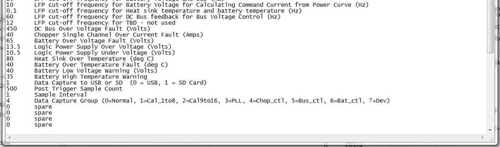
8 There is a fault log stored on the SD card for all faults encountered- fltsxxxx.csv. The highest number xxxx is the latest fault log. Basic data surrounding the fault are stored. Additionally there is high resolution scope data files created during each fault. To avoid filling the SD card with too much data there are only 10 detailed fault scope files stored. The files are overwritten in numerical order. To find the last fault log file look in column Z for the scope file index (shown in yellow below). Then find the scope_xx.csv that corresponds to that fault, in this case scope_03.csv. Keep in mind that only scope logs for the last 10 faults are stored. The scope fault logs show 16 channels of data surrounding the faults, with a 52 µs resolution. There are 2000 samples saved in each scope file. The channels which will be saved are selected from several groups of data, which data group is saved is set in the last line in sysparam.txt (see below) Sysparam.txt contains most of the tuning calibrations; do not change any values except History Logging Interval or Data Capture Group. The history files are long term performance type data that are saved to the SD Card. They are saved at 10 minute increments by default (not the 10 seconds shown below). The Data Capture Group can be changed to help with fault diagnosis in case there are faults that require different high resolution data to diagnose. Rev: 0 June 17,

9 Rev: 0 June 17,


10 The long term data files are stored by default at 10 minute intervals; there is no real time clock in the VCS II so the on time is stored in the first column, with the cumulative energy in kwh stored in the second column. Snapshot data are also stored regarding battery voltage, current, and temperature. To help with turbine and wiring diagnosis all 3 phase voltages, as well as the turbine frequency are stored. The dataxxxx.csv files are the only place that cumulative kwh and run time are stored, so if the files are deleted or modified an incorrect kwh or run time will be displayed. All calibration data are stored in cal_data.txt, these values are determined for each unit during initial testing. They should not need to be altered after initial calibration. Rev: 0 June 17,

11 The power curve is stored as pwrcrv.csv, the format is frequency in column A and power in watts in column B. The frequency must be given in 1 Hz increments up to 150 Hz. Changes to the power curve should not be made without Bergey WindPower Co approval, as damage to the controller or the alternator can occur if improper values are used. Rev: 0 June 17,
 is provided on the controller with a pinout of: Pin 1 NC Pin 2 NC Pin 3 V+ Pin 4 CANH Pin 5 CANL Pin 6 GND Pin 7 NC Pin 8 - NC VCS II CAN Bus Message Specification 1.")
12 VCS II Can Bus Interface The CAN Bus utilizes an isolated input to provide a galvanic isolation rating of 2500 V RMS. An RJ45 connection (CN20) is provided on the controller with a pinout of: Pin 1 NC Pin 2 NC Pin 3 V+ Pin 4 CANH Pin 5 CANL Pin 6 GND Pin 7 NC Pin 8 - NC VCS II CAN Bus Message Specification 1. The baud rate is fixed to 250k. 2. Little endian is used for CAN transmission least significant byte is transmitted/received first. 3. Only standard identifier (11bit) is supported. 4. Message ID Specifications: Message Request Response Comment ID 1 DLC: 1 Mailbox 0 is reserved DLC: 1 Mailbox 16 is reserved This message is for command: 1 = Start (Reset), 0 = Stop. to receive this to echo back the If the system is in regular charge message. original message or equalizer mode, the Stop command will stop the system operation. If the system is in stop mode, the Start command will start the system. If the system is in fault state, the Start(Reset command will clear the fault and prepare the system to go to run state. 2 DLC: 4 Mailbox 1 is reserved to receive this message. Data format: single precision float. DLC: 4 Mailbox 17 is reserved to echo back the original message. Data format: single precision float. This message sets the battery regulation voltage for normal operation. Rev: 0 June 17,
13 Message ID Request Response Comment 3 DLC: 4 DLC: 8 The external controller sends this Mailbox 2 is reserved to receive this message. Data format: Uint32 Mailbox 18 is reserved to send the parameter to external controller. Data format: The first message to DSP to request certain parameter. The parameter ID (PID) is included in the requested message. 4 bytes are Uint32. The DSP responds with the The last 4 bytes are float32 or Uint32, depending on the data parameter filled in the last 4 bytes of the CAN message. The first 4 bytes still holds the PID. item. Rev: 0 June 17,
14 5. Parameter ID Specifications: Parameter ID (PID) Description Data Type 0 High Limit battery voltage target allowed [Vdc] Float32 1 Lo Limit battery voltage target allowed [Vdc] Float32 2 Max output current limit allowed [Adc] Float32 3 Maximum Output Power (W) Float32 4 Hot Start Ramp Timer (s) Float32 5 Firmware revision [na] Float32 6 Equalize voltage reference [Vdc] Float32 7 Battery temperature compensation [V/deg C] Float32 8 VoltTime limit for Equalize mode [Vhr] Float32 9 Regulation voltage reference [Vdc] Float32 10 Energy(kWh) Float32 11 Average battery voltage measured [Vdc] Float32 12 Average output current measured [Adc] Float32 13 Average battery temp measured [deg C] Float32 14 Average heatsink temp measured [deg C] Float32 15 L1-L2 voltage [Vac,rms] Float32 16 L2-L3 voltage [Vac,rms] Float32 17 L3-L1 voltage [Vac,rms] Float32 18 Turbine frequency measured [Hz] Float32 19 System state [na] Uint32 20 Average current measured, chopper 1 [Adc] Float32 21 Average current measured, chopper 2 [Adc] Float32 22 Average current measured, chopper 3 [Adc] Float32 23 Average current measured, chopper 4 [Adc] Float32 24 Average current measured, chopper 5 [Adc] Float32 25 Average current measured, chopper 6 [Adc] Float32 26 Average current measured, chopper 7 [Adc] Float32 27 Average current measured, chopper 8 [Adc] Float32 28 Software current reference [Adc] Float32 29 Bus voltage measured [Vdc] Float32 30 Present fault state[na] Uint32 31 Last fault state cleared Uint32 32 Warnings [na] Uint32 33 Reserved 34 Reserved 35 Reserved 36 Reserved 37 Reserved 38 Reserved Rev: 0 June 17,
15 VCS II Status, Faults, & Warnings The faults and warning messages are basically coded as binary bits, such that multiple faults and warnings can be transmitted. There will be an integer value returned for fault and warning queries. This can be converted to hex and looked up in the tables on the following pages, or if converted to binary then each individual bit indicates a separate fault. Status: Low Wind Speed = Turbine is spinning too slow to generate power. Rev: 0 June 17,
16 VCS II Fault List Fault (PID 30 & 31) Fault, over current chopper 1 [na] Fault, over current chopper 2 [na] Fault, over current chopper 3 [na] Fault, over current chopper 4 [na] Fault, over current chopper 5 [na] Fault, over current chopper 6 [na] Fault, over current chopper 7 [na] Fault, over current chopper 8 [na] Fault, De-saturation chopper 1 [na] Fault, De-saturation chopper 2 [na] Fault, De-saturation chopper 3 [na] Fault, De-saturation chopper 4 [na] Fault, De-saturation chopper 5 [na] Fault, De-saturation chopper 6 [na] Fault, De-saturation chopper 7 [na] Fault, De-saturation chopper 8 [na] Fault, Battery Over Voltage Fault (Volts) Fault, DC bus over voltage [na] Fault, Logic Power Supply Over Voltage (Volts) Fault, Logic Power Supply Under Voltage (Volts) Fault, battery over temp [na] Fault, Heat sink over temp [na] Fault, battery disconnect Fault, Interrupt overrun [na] Fault, alternator phase loss [na] Fault, non-maskable interrupt [na] Fault, D5V [na]- No parameter for this. Uses GPIO Fault, PLL Sync Fault, [EXCESS BUS CLAMPING] Fault, Watchdog [na] Hex Code 0x x x x x x x x x x x x x x x x x x x x x x x x x x x x x x Rev: 0 June 17,
17 VCS II Warning List Warning (PID 32) MS_OUTPUT_POWER MS_BAT_FULL_CHARGED MS_SD_MISSING MS_THERMAL_ACTIVE MS_CAN_COMM_ERROR MS_EQUALIZE_MODE MS_SD_PROTECTED MS_LOW_SPEED MS_MANUAL_MODE MS_BAT_VOL_LOW MS_BAT_TEMP_HIGH MS_PHASE_ROTATION MS_EXT_RAM_FAILED Hex Code 0x x x x x x x x x x x x x Rev: 0 June 17,
18 VCS II Specifications Turbine Input Input current (max) Input voltage (max) Input start voltage minimum (at low battery condition) Input normal operating voltage range Input frequency range Cut-in frequency Cut-out frequency 43 Amps 480 Vrms 30 Vrms 35 Vrms 480 Vrms Hz 15 Hz 10 Hz Battery Output Rated output current (max) Rated output voltage (max) Output start voltage minimum (at low battery condition) Output normal operating voltage range Control method Output overcurrent protection (DC Breaker) 200 Amps 65 Vdc 36 Vdc Vdc Constant Voltage 250 Amps Environmental Enclosure type NEMA 1 / IP60 Overall NEMA 3R / IP66 for internal controls Operating temperature range -20 to 40 C Max altitude 1000 m Thermal derating (approximate ambient temperature) 45 C Thermal shutdown 80 C Weight 106 lb / 48kg Rev: 0 June 17,
19 Performance Rated power (11 m/s) 8 kw Rated RPM 170 Rated windspeed 11 m/s Start-up windspeed 4 m/s Cut-in windspeed 1.8 m/s Cut-out windspeed none Furling windspeed m/s Max design windspeed 60 m/s Rev: 0 June 17,
PV Rapid Shutdown device
 PV Rapid Shutdown device Installation and Operation Manual Solis-RSD-1G(1:1) Solis-RSD-1G(2:2) Manufacturer: Ginlong (Ningbo) Technologies Co.,Ltd., Ningbo, Zhejiang, P.R.China US Office: 565 Metro Pl.
ADC7520 SERIES. 1600W Battery Chargers and Power Supplies
 ADC7520 SERIES 1600W Battery Chargers and Power Supplies Wide output adjustment range 0 72VDC Analog control by external 0-5VDC voltage Temp.comp charging, sense as on option Power fail relay alarm Master-Slave
Torque Series LCD Remote Panel Installation/Operation Manual Model: TQ-DSP-12/24
 Torque Series LCD Remote Panel Installation/Operation Manual Model: TQ-DSP-12/24 Section Page Introduction 1 Materials Provided 1 I) Safety Instructions 1 A) Inverter Safety Instructions 1 B) Battery Safety
S66 Series Electronic Fan Speed Control
 FANs 121, 125, 1628.3 Product/Technical Bulletin S66 Issue Date 0918 S66 Series Electronic Fan Speed Control The S66 Series Electronic Fan Speed Control is designed to modulate the speed of single-phase,
User s Manual. ACS550-PD 3R Irrigation Packaged Drive Supplement to ACS550-U1 User s Manual
 User s Manual ACS550-PD 3R Irrigation Packaged Drive Supplement to ACS550-U1 User s Manual 2 ACS550-PD 3R Irrigation Packaged Drive ACS550 Drive Manuals GENERAL MANUALS ACS550-U1 User s Manual (1 200 HP)
GCI-5K INSTALLATION AND OPERATOR S MANUAL
 GCI-5K INSTALLATION AND OPERATOR S MANUAL Grid-tied inverter for wind Ningbo Ginlong Technologies 1 INTRODUCTION 2 SAFETY GUIDELINES AND WARNINGS 3 INSTALLATION 3.1 Selecting a location for the inverter
TSP-BCM48, TSP-BCM48A. Operating Instruction Manual. Page 1 of 13
 Battery Controller Module TSP-BCM24, TSP-BCM24A TSP-BCM48, TSP-BCM48A Operating Instruction Manual http://www.tracopower.com Page 1 of 13 Dimensions drawings: TSP-BCM24 & TSP-BCM48 Weight: 0.816lb Gewicht:
InView Marquee Message Display
 Installation Instructions InView Marquee Message Display Introduction These instructions show how to change the serial address and how to mount InView series signs with NEMA Types 4, 4X, and 12 enclosures.
MAINTENANCE MANUAL. EDACS REDUNDANT POWER SUPPLY SYSTEM 350A1441P1 and P2 POWER MODULE CHASSIS 350A1441P3, P4, AND P5 POWER MODULES TABLE OF CONTENTS
 MAINTENANCE MANUAL EDACS REDUNDANT POWER SUPPLY SYSTEM 350A1441P1 and P2 POWER MODULE CHASSIS 350A1441P3, P4, AND P5 POWER MODULES TABLE OF CONTENTS SPECIFICATIONS*... 2 INTRODUCTION... 3 DESCRIPTION...
Rhino Buffer Module PSM24-BFM600S. Operating Instructions
 Rhino Buffer Module PSM24-BFM600S Operating Instructions RHINO BUFFER MODULE PSM24-BFM600S Description The PSM24-BFM600S Buffer Module will hold the output voltage of a 24 VDC power supply after brownouts
PanelView Plus/VersaView CE Terminals and Display Modules
 Installation Instructions PanelView Plus/VersaView CE Terminals and Display Modules (Catalog Numbers 2711P-xxxxxx, 6182H-xxxxxx) English Inside: Overview...2 For More Information...2 Modular Components...3
Installation, Operation and Maintenance Manual
 Document 481200 VGD-100 Vari-Green Drive Installation, Operation and Maintenance Manual Please read and save these instructions for future reference. Read carefully before attempting to assemble, install,
User s Manual. ACS550-PD Stock 3R Irrigation Packaged Drive Supplement to ACS550-U1 User s Manual
 User s Manual ACS550-PD Stock 3R Irrigation Packaged Drive Supplement to ACS550-U1 User s Manual 2 ACS550-PD 3R Irrigation Packaged Drive ACS550 Drive Manuals GENERAL MANUALS ACS550-U1 User s Manual (1
SOLARIMMERSION IV Advanced Installation Manual v1.9
 SOLARIMMERSION IV Advanced Installation Manual v1.9 1 Contents 1. Overview 2. Technical Specifications 3. Installation Mounting Electrical Installation Clamp Installation Wiring Diagrams 4. Installation
P216 Series Condenser Fan Speed Controller
 P216 Series Condenser Fan Speed Controller Installation Instructions P216xxx-x Part No. 24-85895-18, Rev. D Issued 27 August 2015 Applications Refer to the QuickLIT website for the most up-to-date version
D115 The Fast Optimal Servo Amplifier For Brush, Brushless, Voice Coil Servo Motors
 D115 The Fast Optimal Servo Amplifier For Brush, Brushless, Voice Coil Servo Motors Ron Boe 5/15/2014 This user guide details the servo drives capabilities and physical interfaces. Users will be able to
Switched Mode Power Supply Operating manual PAP800
 Features: Switched mode power supply Wide output 0 144Vdc Analog control by an external 0 5Vdc Power failure alarm output Master-slave connection Powerfinn PAP series is a high power, lightweight, advanced
CRAGG RAILCHARGER Instruction Manual for 10DTC-12V 20DTC-12V 30DTC-24V 40DTC-12V 60DTC-12V
 CRAGG RAILCHARGER for 10DTC-12V 20DTC-12V 30DTC-24V 40DTC-12V 60DTC-12V Contents 1 Warnings, Cautions, and Notes... 1 2 Description... 2 3 Features... 2 3.1 STANDARD FEATURES... 2 3.2 CHARGER REGULATION...
RT4F-110V/25A RECTIFIER
 The RT4F-110V/25A is a hot-pluggable switched mode rectifier (SMR) module designed to provide up to 25A of output current into a 110V nominal system. Examples of such systems are 60 cells lead acid (136V
Buffered Power Supply PS-30DR v1.0
 Roger Access Control System Buffered Power Supply PS-30DR v1.0 Document version: Rev. C Firmware: 1.0.4 1. PRODUCT DESCRIPTION The PS-30DR is dedicated for electronic equipment which require 12VDC buffered
RT4F-120V/20A-WAC RECTIFIER
 The RT4F-120V/20A-WAC is a switched mode rectifier/charger module designed to provide up to 20A of output current into a 120V nominal system. This charger has been designed for use in conjunction with
Model HM-535 Power Supply Installation and Service Instructions
 Model HM-535 Power Supply Installation and Service Instructions 430-535 0104 2004 Heritage MedCall, Inc SENTRY INSTALLATION & SERVICE INSTRUCTIONS POWER SUPPLY UNIT Model HM-535 IMPORTANT SAFETY INSTRUCTIONS
Dual-Feed 80A Auto Low Voltage Disconnect Panel - 80LVD02
 Dual-Feed 80A Auto Low Voltage Disconnect Panel - 80LVD02 User Manual 1.1 Overview Telect s 80A, -48 Vdc Low-Voltage Disconnect (LVD) panel is a rack-mounted component with coil-operated contactors. These
HCS-3600 / 3602 / 3604 Laboratory Grade & High RFI Immunity Switching Mode Power Supply with Rotary Encoder Control
 HCS-3600 / 3602 / 3604 Laboratory Grade & High RFI Immunity Switching Mode Power Supply with Rotary Encoder Control 1. INTRODUCTION User Manual This family of efficient, upgraded SMPS with small form factor,
5504 Thermocouple Analog Input Module
 550 Thermocouple Analog Input Installation, Operation and Maintenance Setup Manual 5/9/0 Safety Information The information provided in this documentation contains general descriptions and/or technical
REDUNDANCY MODULE TSP-REM360 AND TSP-REM600
 REDUNDANCY MODULE TSP-REM360 AND TSP-REM600 Operating Instructions Seite 1 Dimensions drawings: TSP-REM360 Weight: 0.882lb Gewicht: 0.40kg Seite 2 Dimensions drawings: TSP-REM600 Bottom view Top view Side
ATS22C41Q soft starter-ats22-control 220V-power 230V(110kW)/ V(220kW)
/ V(220kW)") Characteristics soft starter-ats22-control 220V-power 230V(110kW)/400...440V(220kW) Complementary Assembly style Function available Power supply voltage limits Main Range of product Altistart 22 Product
Characteristics soft starter-ats22-control 220V-power 230V(110kW)/400...440V(220kW) Complementary Assembly style Function available Power supply voltage limits Main Range of product Altistart 22 Product
GRID-TIED SOLAR INVERTER 1.5KW ~ 6.0KW V.1.2
 USER MANUAL MPI-1500/2000/3000/4000/6000 Series GRID-TIED SOLAR INVERTER 1.5KW ~ 6.0KW V.1.2 WWW.MPPSOLAR.COM WARNING: ONLY A CERTIFIED ELECTRICIAN OR TRAINED ASSEMBLING PROFESSIONAL SHOULD OPEN OR INSTALL
1395 Node Adapter Board Troubleshooting
 1395 Node Adapter Board Troubleshooting Specifications Electrical: Board power provided by Drive (+5V) Discrete Input 24V DC or 115V AC, jumper selectable Environmental: Ambient Operating Temperature Storage
MAXIMA+ Series Rotary Level Indicator
 MAXIMA+ Series Rotary Level Indicator BinMaster: Division of Garner Industries 7201 N. 98th St., Lincoln, NE 68507 402-434-9102 email: info@binmaster.com www.binmaster.com OPERATING INSTRUCTIONS PLEASE
FLEXmax 100 Charge Controller. Owner s Manual
 FLEXmax 100 Charge Controller Owner s Manual About OutBack Power Technologies OutBack Power Technologies is a leader in advanced energy conversion technology. OutBack products include true sine wave inverter/chargers,
User Manual. Solar Inverter for Water Pump
 User Manual Solar Inverter for Water Pump SP Revival Series Version: 1.2 Table Of Contents ABOUT THIS MANUAL... 1 Purpose... 1 Scope... 1 SAFETY INSTRUCTIONS... 1 Inspection... 1 Installation... 1 Operation...
INSTALLATION INSTRUCTIONS
 Wired Remote Controller 7 Day Programmable Ductless Systems KSACN0401AAA (High Wall Models) KSACN0501AAA (Ducted/Cassette Models) INSTALLATION INSTRUCTIONS NOTE: Read the entire instruction manual before
INSTALLATION MANUAL SLI 50 INVERTER
 INSTALLATION MANUAL SLI 50 INVERTER www.unipowerco.com Manual No. SLI-50-48-3 2016 UNIPOWER LLC All Rights Reserved UNIPOWER LLC 3900 Coral Ridge Drive, Coral Springs, Florida 33065, USA sales@unipowerco.com
Nature Power Inverters. Modified Sinewave 1000w/1500w True Sinewave 1000w/2000w. Owner s Manual
 Nature Power Inverters Modified Sinewave 1000w/1500w True Sinewave 1000w/2000w Owner s Manual Modified Sinewave Series True Sinewave Series For safe and optimum performance, the Power Inverter must be
Symmetra PX 160. Maintenance Bypass Enclosure. Installation 05/
 Symmetra PX 160 Maintenance Bypass Enclosure Installation 05/2014 www.schneider-electric.com Legal Information The Schneider Electric brand and any registered trademarks of Schneider Electric Industries
This Datasheet for the IC660BBA104. Block 115Vac/125Vdc Analog Current Source 4 Inputs / 2 Outputs
 This Datasheet for the IC660BBA104 Block 115Vac/125Vdc Analog Current Source 4 Inputs / 2 Outputs http://www.qualitrol.com/shop/p-14425-ic660bba104.aspx Provides the wiring diagrams and installation guidelines
dv/dt filter compact plus Voltage Peak Limiter SINAMICS SINAMICS G120P dv/dt filter compact plus Voltage Peak Limiter Safety information 1 General 2
 dv/dt filter compact plus Voltage Peak Limiter SINAMICS SINAMICS G120P dv/dt filter compact plus Voltage Peak Limiter Operating Instructions Safety information 1 General 2 Mechanical installation 3 Electrical
ATS22D75Q soft starter-ats22-control 220V-power 230V(18.5kW)/ V(37kW)
/ V(37kW)") Product data sheet Characteristics ATS22D75Q soft starter-ats22-control 220V-power 230V(18.5kW)/400...440V(37kW) Complementary Assembly style Function available Power supply voltage limits Main Range of
Product data sheet Characteristics ATS22D75Q soft starter-ats22-control 220V-power 230V(18.5kW)/400...440V(37kW) Complementary Assembly style Function available Power supply voltage limits Main Range of
Expandable Power Systems
 Expandable Power Systems Installation Guide Models Include: Maximal11EV 12VDC @ 4A or 24VDC @ 3A. 12VDC @ 4A or 24VDC @ 3A. Maximal33EV 12VDC or 24VDC @ 6A. 12VDC or 24VDC @ 6A. Maximal37EV 24VDC @ 10A.
PowerLogic High Density Metering System 1-Meter Enclosure
 PowerLogic High Density Metering System 1-Meter Enclosure Installation Guide 63230-508-211A1 Safety information PowerLogic High Density Metering System 1-Meter Enclosure Important information Read these
VLT Line Filter MCC 107 EMC Filter Series VLT Midi Drive FC 280 (K1 K3)
") These instructions provide technical and installation information for the MCC 107 EMC filter series. Only Danfoss qualified personnel is allowed to install this equipment. The personnel must be familiar
These instructions provide technical and installation information for the MCC 107 EMC filter series. Only Danfoss qualified personnel is allowed to install this equipment. The personnel must be familiar
Magnetek Dynamic Braking Resistors
 Magnetek Dynamic Braking Resistors Motor Control Instruction Manual N49 W13650 Campbell Drive Menomonee Falls, WI 53051 Phone: 1-800-288-8178 Fax: 1-800-298-3503 SERVICE: 1-866-MAG-SERV (1-866-624-7378)
This Datasheet for the IC660BBA026. Block 24/48Vdc Analog Current Source 6 Inputs.
 This Datasheet for the IC660BBA026 Block 24/48Vdc Analog Current Source 6 Inputs http://www.cimtecautomation.com/parts/p-14421-ic660bba026.aspx Provides the wiring diagrams and installation guidelines
PDS8u POWER DISTRIBUTION SYSTEM USER'S MANUAL
 PDS8u POWER DISTRIBUTION SYSTEM USER'S MANUAL 1 IMPORTANT SAFETY INSTRUCTION READ FIRST This symbol, whenever it appears, alerts you to the presence of uninsulated dangerous voltage inside the enclosure-voltage
Configurable Output Distribution. 120V / 208V / 240V 60Hz. User Manual English
 Configurable Output Distribution 120V / 208V / 240V 60Hz User Manual English TABLE OF CONTENTS IMPORTANT SAFETY INSTRUCTIONS.......................... 1 GLOSSARY OF SYMBOLS....................................
Line reactors SINAMICS. SINAMICS G120P Line reactors. Safety information 1. General. Mechanical installation 3. Electrical installation 4
 Safety information 1 General 2 SINAMICS SINAMICS G120P Mechanical installation 3 Electrical installation 4 Technical specifications 5 Operating Instructions Control version V4.6 11/2013 A5E32845290B AA
S&C M Series Switch Operator. Sophisticated Microprocessor Control of Overhead Distribution Switches
 S&C M Series Switch Operator Sophisticated Microprocessor Control of Overhead Distribution Switches S&C s M Series Switch Operator is a fully integrated, microprocessor-based operator that lets you automate
Installation Instructions
 50ES, 50EZ, 50GL, 50GS, 50GX, 50JS, 50JX, 50JZ, 50SD, 50SZ, 50VL, 50VT, 50XP, 50XZ 601A, 602A, 602B, 604A, 604B, 604D, 607C, 701A, 702A, 702B, 704A, 704B, 704D, 707C PA1P, PA2P, PA3P, PH1P, PH2P, PH3P
Regenerative Power Module And Common Bus RPM Panels Instruction Manual
 Regenerative Power Module And Common Bus RPM Panels Instruction Manual Part Number September 2010 Copyright 2010 Magnetek Material Handling PRODUCT MANUAL SAFETY INFORMATION Magnetek, Inc. (Magnetek)
ATS22C17Q. Main. Range of product Altistart 22. Component name. Factory setting current. Utilisation category. IP degree of protection
 Product datasheet Characteristics ATS22C17Q Complementary Assembly style Function available Supply voltage limits Main Range of product Altistart 22 Product or component type Product destination Product
ATS22C11S6U soft starter-ats22-control110vpower208v(30hp)/230v(40hp)/460v(75hp)/575v(100h
/230v(40hp)/460v(75hp)/575v(100h") Characteristics soft starter-ats22-control110vpower208v(30hp)/230v(40hp)/460v(75hp)/575v(100h Complementary Assembly style Function available Power supply voltage limits Main Range of product Altistart
Characteristics soft starter-ats22-control110vpower208v(30hp)/230v(40hp)/460v(75hp)/575v(100h Complementary Assembly style Function available Power supply voltage limits Main Range of product Altistart
MAXIMA + Series ROTARY LEVEL CONTROL
 Price $5.00 MAXIMA + Series ROTARY LEVEL CONTROL OPERATING INSTRUCTIONS PLEASE READ CAREFULLY Division of Garner Industries 7201 North 98th Street Lincoln, NE 68507-9741 (402) 434-9102 925-0268 Rev. A
Series Amp Pad Mount Quick Connect Input and Output Power Panels
 Series 300 2000-4000 Amp Pad Mount Quick Connect Input and Output Power Panels DANGER is used in this manual to warn of a hazard situation which, if not avoided, will result in death or serious injury.
Model HU-224/225. Technical Information TI.224/ Humidity Transduce r FOR ADDITIONAL INFORMATION SEE HU-224/225 DATA SHEET
 Model /225 FOR ADDITIONAL INFORMATION SEE /225 DATA SHEET SPECIFICATIONS Accuracy*: ± 2% / ± 3% RH Range: 0-100% RH Hysteresis: ± 1% Supply Voltage:12-40 VDC 12-35 VAC (VDC output units only) Supply Current:
P216. Condenser fan speed controller. Product bulletin. Features
 P216 Condenser fan speed controller Product bulletin These controllers are designed for speed variation of single phase motors, especially for fan speed control on air cooled condensers. Head pressure
GCI-2G-W Single Phase Inverter
 Wind Grid Tie Inverter GCI-2G-W Single Phase Inverter Installation and Operation Manual -US version Ningbo Ginlong Technologies Co., Ltd. No. 57 Jintong Road, Binhai Industrial Park, Xiangshan, Ningbo,
CPCI-PS24 24V-Power Supply
 24V-Power Supply Hardware Manual to Product I.2301.21 esd electronic system design gmbh Vahrenwalder Str. 207 30165 Hannover Germany http://www.esd.eu Phone: +49 (0) 511 3 72 98-0 Fax: +49 (0) 511 3 72
SLATE. Digital I/O Module INSTALLATION INSTRUCTIONS R8001D4001
 SLATE Digital I/O Module R8001D4001 INSTALLATION INSTRUCTIONS Scan for more information Application SLATE brings configurable safety and programmable logic together into one single platform. The platform
SLK Grid PV-inverter (UL) Installation and Operation Manual
 Installation and Operation Manual") SLK Grid PV-inverter (UL) Installation and Operation Manual Only an electro-skilled person or trained assembly staff can install or open the Inverter. Before you start Thanks for purchasing SLK Grid PV-Inverter.
SLK Grid PV-inverter (UL) Installation and Operation Manual Only an electro-skilled person or trained assembly staff can install or open the Inverter. Before you start Thanks for purchasing SLK Grid PV-Inverter.
Line reactors SINAMICS. SINAMICS G130 Line reactors. Safety information 1. General. Mechanical installation 3. Electrical installation
 Safety information 1 General 2 SINAMICS SINAMICS G130 Mechanical installation 3 Electrical installation 4 Technical specifications 5 Operating Instructions Control version V4.7 04/2014 A5E00331462A Legal
PACSystems RX3i IC695PSA140
 GFK2399A October 2005 PACSystems RX3i IC695PSA140 120/240VAC or 125VC, 40 Watts IC695PSA140 is a multipurpose 40Watt supply that operates from an input voltage source in the range of 85 to 264 VAC or 100
This Datasheet for the IC660BBA101. Block 115Vac/125Vdc RTD Input 6 Channels.
 This Datasheet for the IC660BBA101 Block 115Vac/125Vdc RTD Input 6 Channels http://www.qualitrol.com/shop/p-14423-ic660bba101.aspx Provides the wiring diagrams and installation guidelines for this GE Series
The power behind competitiveness. Delta Infrasuite Power Management. Power Distribution Unit. User Manual.
 The power behind competitiveness Delta Infrasuite Power Management Power Distribution Unit User Manual www.deltapowersolutions.com Save This Manual This manual contains important instructions and warnings
Junos WebApp Secure 5.0 Hardware Guide
 Junos WebApp Secure 5.0 Hardware Guide Junos WebApp Secure 5.0 Hardware Guide This document contains a specification for the MWS1000 hardware appliance, as well as instructions for installation into a
Lighting Energy Management Building Controls. LibRE Installation Guide
 Lighting Energy Management Building Controls LibRE Installation Guide V 0.1 March 2015 1 Safety Information Save These Instructions The following symbols are used throughout this manual to indicate potentially
The PCI Series. Precise power control for complex SCR applications. Phase Angle Fired SCR Power Controls AMPS VAC
 The PCI Series Phase Angle Fired SCR Power Controls 25-1200 AMPS 120-600 VAC Precise power control for complex SCR applications. ROBICON 1996 Distributed Worldwide by www.mcgoff-bethune.com Applications
MicroTech II TM Remote I/O Panel Installation Manual
 Installation Manual IM 783-0 MicroTech II TM Remote I/O Panel Installation Manual Group: Controls Part Number: IM 783-0 Date: February 2004 Supersedes: New 2004 McQuay International Page 2 IM-783 Table
Analyzer/Controller. ph/orp HART. Model 54e ph/orp ESSENTIAL INSTRUCTIONS WARNINGS RISK OF ELECTRICAL SHOCK
 Instruction Sheet PN 51A-54epH/rev J October 2010 ph/orp HART Model 54e ph/orp Analyzer/Controller For additional information, please visit our website at www.emersonprocess.com/raihome/liquid/. ESSENTIAL
Tempco Instruction Manual
 Tempco Instruction Manual 1/16 DIN Solid State Temperature Controller Relay Output Solid State Output For Heating Model Numbers: TEC-901, TEC-902, TEC-905 Temperature controls in this series are designed
ATS22D17Q soft starter-ats22-control 220V-power 230V (4kW)/ V(7.5kW)
/ V(7.5kW)") Product datasheet Characteristics ATS22D17Q soft starter-ats22-control 220V-power 230V (4kW)/400...440V(7.5kW) Complementary Assembly style Function available Supply voltage limits Main Range of product
Product datasheet Characteristics ATS22D17Q soft starter-ats22-control 220V-power 230V (4kW)/400...440V(7.5kW) Complementary Assembly style Function available Supply voltage limits Main Range of product
Installation, Testing, and Operating Procedures 30 AMP PORTABLE AND PERMANENT SERIES GFCI SINGLE and MULTIPHASE
 IMPORTANT! Please read all the information on this sheet. SAVE THESE INSTRUCTIONS! NOTICE BEFORE USING READ INSTRUCTIONS COMPLETELY. TO BE INSTALLED BY A QUALIFIED ELECTRICIAN IN ACCORDANCE WITH NATIONAL
THOR Battery Backed DC Power Supply Reference Manual
 THOR Battery Backed DC Power Supply Reference Manual Revision A Firmware Compatibility: V1.03 P/N 60098001 Revised: 4/26/2012 INDUSTRIAL CONTROL LINKS, INC. 12840 Earhart Avenue Auburn, CA 95602 Tel: (800)
User's Guide. Model W 3-in-1 Switching DC Power Supply
 User's Guide Model 382260 80W 3-in-1 Switching DC Power Supply Introduction Congratulations on your purchase of the Extech 80W 3-in-1 Switching DC Power Supply. The Model 382260 has three output ranges
This Datasheet for the IC660BBD110. Block 115Vac Input 16 Circuits.
 This Datasheet for the IC660BBD110 Block 115Vac Input 16 Circuits http://www.cimtecautomation.com/parts/p-14435-ic660bbd110.aspx Provides the wiring diagrams and installation guidelines for this GE Series
Solis 4G Single Phase Inverter
 PV Grid Tie Inverter Solis 4G Single Phase Inverter Installation and Operation Manual -US version Solis-1P6K-4G-US, Solis-1P7K-4G-US, Solis-1P7.6K-4G-US, Solis-1P7.6K4-4G-US, Solis-1P8K-4G-US, Solis-1P8.6K-4G-US,
USER MANUAL VIBRATION CONTROL RMA-POWER-BOX 107/230
 USER MANUAL VIBRATION CONTROL Version 2.2 1 IMPORTANT NOTES Electrical danger within the meaning of this documentation or the warning labels on the product itself respectively means that death, serious
HT2000 Transverter Installation & Operation Manual
 HT2000 Transverter Installation & Operation Manual 1 A message from the team at Heart Transverter S.A. Thanks for your recent purchase of the HT2000 Power inverter in combination with the HTREM Remote
Rhino Redundancy Module PSM24-REM360S. Operating Instructions
 Rhino Redundancy Module PSM4-REM360S Operating Instructions RHINO REDUNDANCY MODULE PSM4-REM360S Description With this module and two power supplies of the PSM series (78, 90, 56, 80 and 360 watt models),
Modified Sinewave Series. Power Inverter 1000/1500 MW 1210, MW1215. True Sinewave Power Inverter 1000/2000 SW 1210, SW 1220.
 Modified Sinewave Power Inverter 1000/1500 MW 1210, MW1215 True Sinewave Power Inverter 1000/2000 SW 1210, SW 1220 Owner s Manual Modified Sinewave Series True Sinewave Series 1. INTRODUCTION Thank you
This Datasheet for the IC697CHS790. Rack, 9 Slots, Rear Mount.
 This Datasheet for the IC697CHS790 Rack, 9 Slots, Rear Mount. http://www.cimtecautomation.com/parts/p-14771-ic697chs790.aspx Provides the wiring diagrams and installation guidelines for this GE Series
Power Supplies IC697PWR724/CE697PWR724
 7 1 IC697PWR724/CE697PWR724 GFK-1047F, 90W Power Supply Module (IC697PWR724/CE697PWR724) datasheet GFK-1047F Features Operation from Three output voltages, 90 watts total +5 VDC output up to 18 amps +12
Rotork Fairchild PAX1 Linear Actuator User s Manual
 Rotork Fairchild PAX1 Linear Actuator User s Manual Product Overview The PAX1 is a flexible low voltage DC powered linear actuator featuring a 5 mm maximum thrust rod stroke moving at speeds up to 0 mm/min
BCM2 Series Branch Circuit Monitors Quick Setup Guide
 BCM2 Series Branch Circuit Monitors Quick Setup Guide Safety Information DANGER! HAZARD OF ELECTRIC SHOCK, EXPLOSION, OR ARC FLASH Follow safe electrical work practices. See NFPA 70E in the USA, or applicable
ATS22D62Q soft starter-ats22-control 220V-power 230V(15kW)/ V(30kW)
/ V(30kW)") Characteristics soft starter-ats22-control 220V-power 230V(15kW)/400...440V(30kW) Main Range of product Altistart 22 Product or component type Product destination Product specific application Component
Characteristics soft starter-ats22-control 220V-power 230V(15kW)/400...440V(30kW) Main Range of product Altistart 22 Product or component type Product destination Product specific application Component
QUICK SETUP GUIDE. BCM2 Series Branch Circuit Monitors. Safety Information. Equipment Maintenance and Service. Raritan DANGER!
 QUICK SETUP GUIDE BCM2 Series Branch Circuit Monitors Safety Information DANGER! HAZARD OF ELECTRIC SHOCK, EXPLOSION, OR ARC FLASH Follow safe electrical work practices. See NFPA 70E in the USA, or applicable
RT4F-48V/50A-WAC RECTIFIER
 The RT4F-48V/50A-WAC is a switched mode rectifier (SMR) module designed to provide up to 58A of output current into a 48V nominal system, over a wide range of AC input voltage. This rectifier has been
INSTRUCTION MANUAL TRIP CIRCUIT SUPERVISION RELAY GKAD1
 INSTRUCTION MANUAL TRIP CIRCUIT SUPERVISION RELAY GKAD1 TOSHIBA Corporation 2004 All Rights Reserved. ( Ver. 1.6 ) Safety Precautions Before using this product, please read this chapter carefully. This
True Sinewave Power Inverter 1000W & 2000W 230V , Owner s Manual
 True Sinewave Power Inverter 1000W & 2000W 230V 21100-03, 21200-03 Owner s Manual For safe and optimum performance, the Power Inverter must be used properly. Carefully read and follow all instructions
Laboratory Switch Mode Power Supply Series. Instruction Manual
 Laboratory Switch Mode Power Supply Series Instruction Manual Model 72-8340 1.0 ~ 60VDC 0 ~ 1.6A 72-8345 1.0 ~ 36VDC 0 ~ 3A 72-8350 1.0 ~ 20VDC 0 ~ 5A Copyright 2008, all rights reserved Tenma Test Equipment
Girard Awnings R ACMC Motor Controller (Last revised on May 10, 2008) A Visionary Awning Control by
 A Visionary Awning Control by") Girard Awnings R ACMC Motor Controller (Last revised on May 10, 2008) R A Visionary Awning Control by Girard AC Motor Controller Installation Guide ACMC Revision 2.08 May 10, July 2008 ACMC Installation
Girard Awnings R ACMC Motor Controller (Last revised on May 10, 2008) R A Visionary Awning Control by Girard AC Motor Controller Installation Guide ACMC Revision 2.08 May 10, July 2008 ACMC Installation
Omnitron Systems Technology, Inc. 1. iconverter. 19-Module Managed Power Chassis User s Manual
 Omnitron Systems Technology, Inc. 1 iconverter 19-Module Managed Power Chassis User s Manual 27 Mauchly, #201, Irvine, CA 92618 Phone: (949) 250-6510; Fax: (949) 250-6514 2 Omnitron Systems Technology,
Integrated Stepper Drive & Motor
 SMD23 Integrated Stepper Drive & Motor Manual #: 940-0S050 User Manual AMCI Motion Control Products Important User Information The products and application data described in this manual are useful in a
ETM MD100 Drive System 1/2HP (370W) User Manual. Table of Contents. Drive Features
 User Manual. Table of Contents. Drive Features") Table of Contents Drive Features... 1 Drive Specifications... 2 Certifications... 3 Installation - Drive Dimensions... 3 Motor Dimensions (mm)... 4 Drive Mounting... 4 Wiring... 5 I/O Terminals... 9 Menu...
Table of Contents Drive Features... 1 Drive Specifications... 2 Certifications... 3 Installation - Drive Dimensions... 3 Motor Dimensions (mm)... 4 Drive Mounting... 4 Wiring... 5 I/O Terminals... 9 Menu...
Solar Combiner Enclosure
 Installation Instructions Solar Combiner Enclosure Catalog Numbers 1000-SB006, 1000-SB012 Topic Page Description 1 Important Safety Instructions 3 Nameplate Data 4 Planning for Installation 4 Install the
XPSMCMx Fieldbus Expansion Modules Instruction Sheet (Original Language)
") XPSMCMx Fieldbus Expansion Modules EAV8283001 12/2014 XPSMCMx Fieldbus Expansion Modules Instruction Sheet (Original Language) 12/2014 EAV8283001.00 www.schneider-electric.com The information provided
XPSMCMx Fieldbus Expansion Modules EAV8283001 12/2014 XPSMCMx Fieldbus Expansion Modules Instruction Sheet (Original Language) 12/2014 EAV8283001.00 www.schneider-electric.com The information provided
BS 287 DUAL CHANNEL POWER SUPPLY. User Manual. January 2017 V1.0
 BS 287 DUAL CHANNEL POWER SUPPLY User Manual January 2017 V1.0 Table of contents 1.0 SAFETY INSTRUCTIONS... 3 2.0 GENERAL DESCRIPTION PS 289... 4 3.0 MECHANICAL INSTALLATION... 5 4.0 MAINS POWER & SAFETY
AIR COOLED MODULAR RECTIFIER
 CONTROLLED POWER COMPANY SPECIFICATIONS AIR COOLED MODULAR RECTIFIER Spc1800a1 5JAN1999 SPECIFICATION S-1800-A MODULAR (REMOVABLE AND NON-REMOVABLE MODULES) AIR COOLED RECTIFIER Standard output power range:
Quick Start Guide TS A
 Quick Start Guide TS 930 125-630A DANGER HAZARD OF ELECTRICAL SHOCK, EXPLOSION, OR ARC FLASH Read and understand this quick start guide before installing and operating the transfer switch The installer
H704-42(H)(E), H704-42/1(H)(E)
(E), H704-42/1(H)(E)") POWER MONITORING INSTALLATION GUIDE H704-42(H)(E), H704-42/1(H)(E) Branch Current Monitor DANGER NOTICE Installer's Specifications General: Operating Temp. Range 0 to 60 C (32 to 140 F) (
POWER MONITORING INSTALLATION GUIDE H704-42(H)(E), H704-42/1(H)(E) Branch Current Monitor DANGER NOTICE Installer's Specifications General: Operating Temp. Range 0 to 60 C (32 to 140 F) (