Product Catalog FIBEROPTIC TEST & MEASUREMENT
|
|
|
- Kerrie Webster
- 6 years ago
- Views:
Transcription


1 Product Catalog FIBEROPTIC TEST & MEASUREMENT
2 TABLE OF CONTENT INTRODUCTION CORPORATE OVERVIEW...3 PRODUCTS WIDE BAND COMPONENT TEST SYSTEM WCS Wide Band Component Test System...5 TUNABLE LASERS TLS5 Tunable Laser Source...8 ENVIRONMENTAL OPTICAL TEST SYSTEM EOTS Environmental Optical Test System OPTICAL ATTENUATORS OA1 MEMS Attenuator OA5 Benchtop Optical Attenuator OPTICAL SWITCHES SX1 MEMS Switch SX4 Benchtop Optical Switch SX8 Rackmount Optical Switch CABLE ASSEMBLY TEST SYSTEM MS12001 System Overview MS12 Return Loss Module MS12-PM Power Meter Module MS7 Optical Switch Module MS4 Polarity Test Module MS Mainframes BACKREFLECTION METERS BR5 Backreflection Meter MBR5 Multi-Channel Backreflection Meter PDL5 Polarization Dependent Loss Meter POLARITY TESTING PT5 Polarity Tester CS Inspection Scopes ACCESSORIES...66 REPAIR AND CALIBRATION...70

3 Established in 2002, JGR has steadily grown to meet the demands of the Fiber Optic test and measurement market. JGR s meticulous approach to service has helped build strong and lasting relationships with their customers, making them the trusted suppliers of equipment and calibration services to key industry players worldwide. JGR s headquarters and fiber optic production facility is located in Ottawa, Canada. Since the introduction of the innovative, industry-leading, Backreflection Meter (BR5) and Multi-Channel Backreflection Meter (MBR5), JGR has expanded their portfolio to include the widely used MS12001 Cable Assembly Test System, and industry leading Benchtop (SX4) and Rackmount (SX8) Optical Switches. Through recent development JGR now also offers the newly introduced Optical Attenuators (OA5), Polarization Dependent Loss Meter (PDL5), and their ultrawide wavelength range Tunable Laser Source (TLS5). In addition to research, development, and production within the JGR facility in Ottawa, Canada, they operate an ISO 17025:2005 Accredited Laboratory for repair and NISTtraceable calibration services. JGR has built its success by listening to its customers, understanding their requirements and acting quickly to bring products and services to the market that they need. Contact JGR to discuss your testing requirements today! 3

4 Wide Band Component Test System


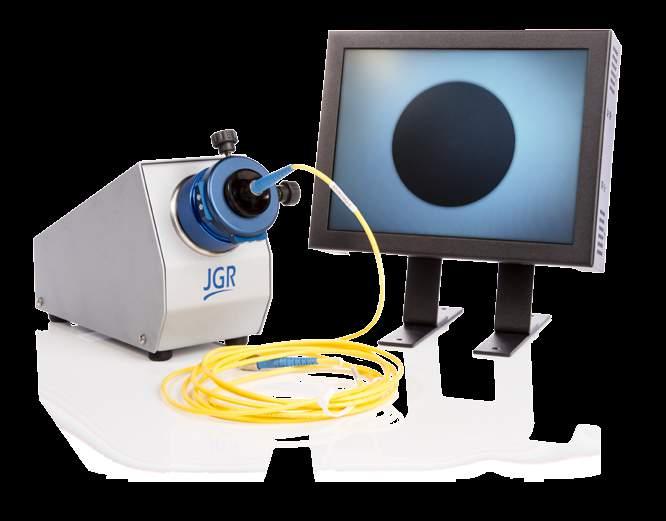
5 WCS Wide Band Component Test System Product Description The WCS Wideband Component Test System takes advantage of JGR s powerful and cost effective ultra-wide band TLS, thus providing fast and reliable measurements across the entire O, E, S, C, L and U wavelength ranges in one single sweep. The WCS is capable of characterizing 32-Channel components such as broadband splitters and CWDM s in less than 10 seconds. With the included WCS software, users can setup PASS/FAIL criteria on their devices and view real time graphical results of IL vs wavelength. Wavelength Range (nm) Model O E S CL W KEY FEATURES 1260 to 1650 wavelength range Fast scanning (<10 seconds for the entire band) Up to 32 Channels per chassis and 256 per system APPLICATIONS Broadband coupler testing CWDM testing FTTH/PON Splitter testing Attenuator testing IN THE SYSTEM TLS5 Tunable Laser WCS Detector Chassis High Speed Detector modules WCS application JGR Optics Inc. 160 Michael Cowpland Dr. Ottawa, Ontario K2M 1P6 CANADA T F info@jgroptics.com
6 Ordering Scheme WCS- - BAND O E S CL W Example: 4-Channel 8-Channel 12-Channel Channel PDL No PDL leave blank P PDL NUMBER OF CHANNELS WCS-W-32P Specifications OPTICAL/ELECTRICAL SPECIFICATIONS Parameter Specification O E S CL W Wavelength Range (nm) Wavelength Accuracy (nm) ± 0.1 Wavelength Resolution (nm) 0.1 Insertion Loss Dynamic Range (db) 1 70 Insertion Loss Dynamic Range with PDL (db) 1 65 Insertion Loss Accurancy (db) 2 ± 0.03 Backreflection Dynamic Range (db) 0 to -65 Backreflection Accuracy (db) 3 ± 0.7 PDL Accurancy (db) ± 0.01 PDL Dynamic Range (db) 0 to 5 Maximum number of Channels Ch Measurement Time(s) 4 <5 <10 1. For TLS output power >-5dBm 2. <30dB IL 3. Add +/-0.1dB for every 1dB below -54dB 4. PDL measurement requires additional 3 measurement sweeps 6
7 Tunable Lasers

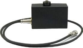
8 TLS5 Tunable Laser Source Product Description The TLS5 Tunable Laser Source delivers an ultra-wide continuous wavelength range covering the complete CWDM spectral range from 1260 nm to 1650 nm at a resolution of 0.1 nm. The TLS5 features a high Side Mode Suppression Ratio (SMSR) of over 60dB, low coherence length and high repeatability, making this source perfect for the characterization of CWDM, PON, various optical components, and for general lab uses. The output power of the TLS5 is typically between -5 dbm to + 5 dbm. KEY FEATURES Ultra wide 1260 nm to 1650 nm continuous wavelength range Resolution of 0.1 nm Side Mode Suppression Ratio 60 db at 0.1 nm resolution bandwidth APPLICATIONS CWDM and PON component testing General lab use Test and measurement Wavelength Range (nm) Model O E S CL W COMPLIANCE UL/CSA IEC FCC Part 15 (Class A) EN (Class A) IN THE BOX TLS5 Tunable Laser Source Hybrid jumper AC power cord JGR Optics Inc. 160 Michael Cowpland Dr. Ottawa, Ontario K2M 1P6 CANADA T F info@jgroptics.com
9 Specifications OPTICAL / ELECTRICAL SPECIFICATIONS Parameter Specification O E S CL W Wavelength Range (nm) Power Stability (db) 1 ±0.01 ±0.07 FWHM (nm) 0.1 Power Repeatability (db) 2 ± 0.02 Output Power (dbm) -5 to nm BW (db) >60 Wavelength Stability (pm) 3 ±8 Wavelength Accuracy (pm) ±50 Wavelength Repeatability (pm) ±50 Resolution (nm) 0.1 Tuning Speed (nm/s) 4 25 High Frequency Modulation (khz) 75 Output Type Panda PM fiber Output Connector FC / APC PER, PM output (db) 18 Communication Interfaces 5 RS-232C, GPIB (IEEE-488.1) and BNC Laser Safety Classification Class 3R Notes: 1 Over 15 minutes 2 At constant temperature 3 Over 1h at constant temperature nm/s available 5 BNC for modulated Trig IN/OUT Ordering Scheme TLS5 - -FA BAND O E S CL W
10 Environmental Optical Test System

 and mandrel free Return Loss (RL) of up to 210 channels, the EOTS is the perfect solution to perform compliance testing of components being stressed")
 1XN optical switches Computer")
11 EOTS Environmental Optical Test System KEY FEATURES Mandrel free Return Loss testing 4 Single-mode lasers built-in Available for Single-mode and Multimode EF compliant for Multimode Bi-directional or Unidirectional APPLICATIONS Passive optical components design and validation Patchcord and cable assembly certification Compliance testing Product Description Built upon the same technology as the industry leading MS12 Return Loss Meter and SX8 Optical Switches the EOTS Environmental Optical Test System provides a fully integrated solution for long-term testing of optical components. With its capability to measure Insertion Loss (IL) and mandrel free Return Loss (RL) of up to 210 channels, the EOTS is the perfect solution to perform compliance testing of components being stressed in environmental simulations. COMPLIANCE Conforms to GR-326-CORE, GR CORE, GR-910-CORE, GR-1209-CORE, GR-2866-CORE, Verizon FOC IN THE SYSTEM 19 Rackmount cabinet MS10R mainframe MS12 module(s) 1XN optical switches Computer and display 1500 VA UPS EOTS application 11 JGR Optics Inc. 160 Michael Cowpland Dr. Ottawa, Ontario K2M 1P6 CANADA T F info@jgroptics.com
12 Ordering Scheme EOTS- - - NUMBER OF CHANNELS Example: EOTS FA00LU1 SOURCES /1300 nm 1310/1550 nm 1310/1490/1550/1625 nm FIBER TYPE Single-mode 9 µm Multimode 50 µm Multimode 62.5 µm CONNECTOR TYPE FA SA FC/APC SC/APC OUTPUT/INPUT PANEL POSITION L R PIGTAIL LENGTH Bulkheads 1.0m 2.0m 3.0m m CONFIGURATION U B Left side Right side INPUT VOLTAGE V 220V Unidirectional Bi-directional 12
13 Specifications OPTICAL / ELECTRICAL SPECIFICATIONS Parameter Specification Single-mode Multi-mode Fiber type (μm) 9/125 50, 62.5 Operating wavelengths (nm) 1310, 1490, 1550 or , 1300 Maximum number of channels 210 Input / 210 Output Insertion Loss Repeatability (db) ± 0.04 ± 0.04 Return Loss Dynamic Range (db) Return Loss Repeatability (db) 4 ± 0.1 (30 to 65) ± 0.5 (<40) ± 0.25 (65 to 70) ± 2.0 (>40) ± 0.5 (>70) Power Consumption ~ 400 VA Power Backup 1 5 hours Computer Control Core i5, 8GB RAM and 2x 1TB hard drives in RAID 1 configuration for full data redundancy Notes: 1 With included Tripplite 1500VA Uninterruptible Power Supply MECHANICAL / ENVIRONMENTAL SPECIFICATIONS Parameter Specification Mechanical Configuration All equipment is installed in a single bay 35U 19 rack with removable covers and doors. Cabinet includes casters and levelers, front & rear doors to access instruments. Side access panel with FC bulkheads. Cabinet dimensions W x H x D (cm) 61 x 177 x 84 Shipping crate dimensions W x H x D (cm) 75 x 192 x 105 System Weight (kg) ~ 180 Total Shipment Weight (kg) 250 Operating Temperature ( C) 0 to 40 Humidity (Non-condensing) Maximum 80% RH from 0 to JGR Optics Inc. 160 Michael Cowpland Dr. Ottawa, Ontario K2M 1P6 CANADA T F info@jgroptics.com
14 Optical Attenuators
 or link loss simulation.")
15 OA1 MEMS Attenuator Product Description The OA1 MEMS Optical Attenuator can support up to 16 MEMs based variable attenuators in a single 1U unit. The OA1 low insertion loss and high repeatability provides all the features required for Bit Error Rate Testing (BERT) or link loss simulation. With it s high density, the OA1 is the perfect tool for manufacturing applications. The OA1 MEMS Optical Attenuator offers an attenuation range of 40 db and is available with single-mode fiber. To provide the flexibility required to adapt to all manufacturing environments, the OA1 is available with connectors on the front panel, or with pigtails on the front or back panels. The OA1 remote interface can be controlled via Ethernet or USB. KEY FEATURES 40 db attenuation range Low insertion loss: 0.8 db Up to 16 attenuators in 1U rackmount unit APPLICATIONS BER testing High volume manufacturing COMPLIANCE UL/CSA IEC FCC Part 15 (Class A) EN (Class A) IN THE BOX OA1 Rackmount Optical Attenuator AC power cord Test report 15 JGR Optics Inc. 160 Michael Cowpland Dr. Ottawa, Ontario K2M 1P6 CANADA T F info@jgroptics.com
16 Ordering Scheme OA NUMBER OF ATTENUATORS 1-Attenuator 2-Attenuators 3-Attenuators Attenuators Example: OA LA00BE CONNECTOR TYPE LP LA LC/UPC LC/APC PIGTAIL LENGTH Bulkheads 1.0 m 2.0 m 3.0 m m REMOTE CONTROL U E USB Control Ethernet Control PIGTAIL POSITION B Bulkheads* F Front of Chassis R Front of Chassis * front option only 16
17 Specifications OPTICAL / ELECTRICAL SPECIFICATIONS Parameter Specification Single-mode Fiber Type (um) 9/125 Wavelength Range (nm) Insertion Loss (db)¹ <0.8 Backreflection (db)¹ <-55 PDL (db) <0.20 Repeatability (db)² +/-0.05 Attenuation Range (db) 40 Maximum Input Power (dbm) 27dBm Input Voltage V AC, Hz Power Consumption (VA) 80 maximum Control USB or Ethernet Notes: 1 Excluding connectors cycles MECHANICAL / ENVIRONMENTAL SPECIFICATIONS Parameter Specification Unit Dimensions W x H x D (cm) 48.3 x 4.4 x 45.7 Shipping Box Dimensions W x H x D (cm) 53 x 20 x 55 Unit Weight (kg) 5 Total Shipment Weight (kg) 6 Operating Temperature ( C) 0 to 55 Storage Temperature ( C) 40 to 70 Humidity (Non-condensing) Maximum 95% RH from 0 to JGR Optics Inc. 160 Michael Cowpland Dr. Ottawa, Ontario K2M 1P6 CANADA T F info@jgroptics.com

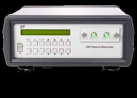
18 OA5 Benchtop Optical Attenuator Product Description The OA5 Benchtop Optical Attenuators enable precise optical power control featuring high accuracy and superior repeatability. The OA5 s are ideal for lab and production applications including power level adjustment in automated test systems, BER testing of transmitters and receivers, and channel equalization in WDM systems. The OA5 model is a benchtop instrument offering dynamic range of up to 100 db (depending on the model configuration). The OA5 remote interface can be controlled via GPIB, RS232, USB*, or locally via the user-friendly front panel keypad and display, simplifying the selection and confirmation of attenuation levels. OA5 series attenuators may be calibrated to particular wavelengths and made to a variety of configuration options offering flexibility for all applications. *USB interface via-usb-db9 adapter KEY FEATURES Precise optical power ± 0.1 db Accuracy ± 0.01 db Repeatability 100 db Dynamic range Optional new Flexcore (5/125 μm) Fiber testing APPLICATIONS Manufacturing production testing BER testing Channel equalization COMPLIANCE UL/CSA IEC FCC Part 15 (Class A) EN (Class A) IN THE BOX OA5 Attenuator AC power cord 18 JGR Optics Inc. 160 Michael Cowpland Dr. Ottawa, Ontario K2M 1P6 CANADA T F info@jgroptics.com
19 Ordering Scheme Short Range Version OA5 - S - FIBER TYPE /125 µm 9/125 µm 50/125 µm 62.5/125 µm CONNECTOR TYPE FP FA SP SA FC/UPC FC/APC SC/UPC SC/APC POWER MONITORING No Power Monitoring P Power Monitoring Long Range Singlemode 9/125 Version OA5- L CONNECTOR TYPE FP FA SP SA FC/UPC FC/APC SC/UPC SC/APC POWER MONITORING No Power Monitoring P Power Monitoring 19
20 Specifications OPTICAL / ELECTRICAL SPECIFICATIONS Parameter Specification Single-mode Multimode Flexcore Long Short Short Short Wavelength Range (nm) Attenuation Range (db) Insertion Loss (db) 1 SM (9 / 125μm) MM (50 or 62.5 / 125μm) HI1060 (5 / 125μm) 2.5 Return Loss (db) SM (9 / 125μm) 60 MM (50 or 62.5 / 125μm) 4 35 HI1060 (5 / 125μm) 50 PDL (db) < 0.1 Repeatability (db) ± 0.01 Resolution (db) ± 0.01 Absolute Accuracy (db) ± 0.1 Max. Optical Input Power (dbm) 23 (200mW) Beam Block (db) > 100 Input Voltage V AC, Hz Interface Front Panel / GPIB / RS232 / USB 5 Notes: 1 Excluding connectors and couplers. 2 At 1550nm. 0.3 db higher at 1310nm. 3 At 850nm. 0.3dB lower at 1310nm. 4 At nm. 5 USB interface via USB-DB9 adapter. MECHANICAL / ENVIRONMENTAL SPECIFICATIONS Parameter Specification Unit Dimensions W x H x D (cm) 26 x 11 x 26 Shipping Box Dimensions W x H x D (cm) 37 x 25 x 38 Unit Weight (kg) 3 Total Shipment Weight (kg) 4 Operating Temperature ( C) 0 to 40 Storage Temperature ( C) 40 to 70 Humidity (Non-condensing) Maximum 95% RH from 0 to JGR Optics Inc. 160 Michael Cowpland Dr. Ottawa, Ontario K2M 1P6 CANADA T F info@jgroptics.com

21 Optical Switches

22 SX1 MEMS Switch Product Description The SX1 Optical Switch can support up to 26 MEMs based switches in a compact 1U rackmount chassis. Each optical switch in the SX1 can support up to 16 output channels. The SX1 low insertion loss, fast switching time and small size makes them one of the most effective switching solution for manufacturing on the market. To provide the flexibility required to adapt to all manufacturing environments, the SX1 is available with connectors on the front panel, or with pigtails on the front or back panels. The SX1 remote interface can easily be controlled via Ethernet or USB. KEY FEATURES Switching Time < 30ms Output channels from 2 to 16 Low insertion loss: 1.2 db Backreflection: -50 db Up to 80 LC ports in a 1U rack APPLICATIONS Multiple device testing High volume production testing R&D applications Compliance testing COMPLIANCE UL/CSA IEC FCC Part 15 (Class A) EN (Class A) IN THE BOX SX1 Rackmount Optical Switch AC power cord Test report 22 JGR Optics Inc. 160 Michael Cowpland Dr. Ottawa, Ontario K2M 1P6 CANADA T F info@jgroptics.com
23 Ordering Scheme SX1- - 1A NUMBER OF SWITCHES OUTPUTS PER SWITCH PIGTAIL LENGTH REMOTE CONTROL 1-Switch 2-Switches 3-Switches Switches Channel 4-Channel 8-Channel 12-Channel 16-Channel Bulkheads 1.0 m 2.0 m 3.0 m m U E USB Control Ethernet Control Example: SX1-16-1A-04-09LA00BE CONNECTOR TYPE LP LA LC/UPC LC/APC PIGTAIL POSITION B Bulkheads* F Front of Chassis R Front of Chassis * front option only 23
24 Specifications OPTICAL / ELECTRICAL SPECIFICATIONS Parameter Specification Single-mode Wavelength Range (nm) Insertion Loss (db) 1 <1.2 Backreflection (db) 1 <-50 PDL (db) <0.15 Repeatability (db)² +/-0.05 Crosstalk (db) <-55 Maximum Input Power (dbm) 27 Switching Time (ms) <30 Input Voltage V AC, Hz Power Consumption (VA) 80 maximum Control USB or Ethernet Switch Life 10 9 cycles Notes: 1 Excluding connectors cycles MECHANICAL / ENVIRONMENTAL SPECIFICATIONS Parameter Specification Unit Dimension W x H x D (cm) 48.3 x 4.4 x 45.7 Shipping Box Dimensions W x H x D (cm) 53 x 20 x 55 Unit Weight (kg) 5 Total Shipment Weight (kg) 6 Operating Temperature ( C) 0 to 55 Storage Temperature ( C) 40 to 70 Humidity (Non-condensing) Maximum 95% RH from 0 to JGR Optics Inc. 160 Michael Cowpland Dr. Ottawa, Ontario K2M 1P6 CANADA T F info@jgroptics.com


25 SX4 Benchtop Optical Switch Product Description The SX4 Benchtop Optical Switch are benchtop instruments ideal for manufacturing production testing. A variety of front panel configurations including 1x2 up to 1x24 are available. The SX4 offers low insertion loss and excellent repeatability, with the advantage of ease of use and portability. The switch is controlled via remote interface (GPIB, RS232, or USB*) or locally via the user-friendly front panel keypad and display. For additional flexibility, the front panel bulkheads may be fitted with typical FC, SC, LC connector types or customizable configurations available. *USB interface via-usb-db9 adapter KEY FEATURES 1A, 2B, 2C configurations Low IL at 0.7 db Single-mode or multimode APPLICATIONS Manufacturing production testing Multiple device testing R&D applications System compliance testing COMPLIANCE UL/CSA IEC FCC Part 15 (Class A) EN (Class A) IN THE BOX SX4 Switch AC power cord Test Report 25 JGR Optics Inc. 160 Michael Cowpland Dr. Ottawa, Ontario K2M 1P6 CANADA T F info@jgroptics.com
26 Configuration Options 1A x N 2B x N 2C x N A.. O n A B O 1A 2A 3A.. na.. O 1B 2B 3B nb O O 1 B 2 A 3 n-1 n O Position 0 Position 0 Position 0 A Configuation - Single input, switched to any output 2B Configuation - Two inputs switched to synchronized outputs 2C Configuation - Two inputs switched to any output with second input trailing first input Ordering Scheme SX CONFIGURATION 1A 2B 2C 1 input, A-config. 2 inputs, B-config. 2 inputs, C-config. OUTPUTS FIBER TYPE /125 µm 50/125 µm 62/125 µm 100/125 µm 200/225 µm 300/325 µm CONNECTOR TYPE FP FA SP SA LP LA FC/UPC FC/APC SC/UPC SC/APC LC/UPC LC/APC PIGTAIL LENGTH PIGTAIL POSITION B F bulkheads 1.0 m 2.0 m 3.0 m m bulkheads front of chassis 26
27 Specifications OPTICAL / ELECTRICAL SPECIFICATIONS Parameter Specification Single-mode Multimode Wavelength Range (nm) Insertion Loss (db) Backreflection (db) PDL (db) 0.05 N/A Repeatability (random switching) (db) ± Repeatability (sequential) (db) ± Crosstalk (maximum) (db) 80 Maximum Input Power (mw) 300 Switching Time (ms) 300 Input Voltage V AC, Hz Power Consumption (VA) 60 maximum Control Front Panel / GPIB / RS232 / USB 2 Switch Life 10 8 cycles Notes: 1 Excluding connectors. 2 USB interface via USB-DB9 adapter. MECHANICAL / ENVIRONMENTAL SPECIFICATIONS Parameter Specification Unit Dimensions W x H x D (cm) 25 x 12 x 27 Shipping Box Dimensions W x H x D (cm) 37 x 25 x 38 Unit Weight (kg) 3 Total Shipment Weight (kg) 4 Operating Temperature ( C) 0 to 55 Storage Temperature ( C) 40 to 70 Humidity (Non-condensing) Maximum 95% RH from 0 to JGR Optics Inc. 160 Michael Cowpland Dr. Ottawa, Ontario K2M 1P6 CANADA T F info@jgroptics.com


28 SX8 Rackmount Optical Switch Product Description The SX8 Rackmount Optical Switch are customizable benchtop/rackmount instruments ideal for high-volume manufacturing production testing. Available in single-mode or multi- mode, the switch configurations range from 1x2 up to 1x360. Optional 2x1 or 4x1 built-in switches can provide additional common inputs. The switch may be controlled through remote interface (GPIB, RS232, or USB*) or locally via the user-friendly front panel keypad and display. A variety of configuration options offers additional flexibility. The front panel bulkheads may be fit with typical FC, SC, LC connector types or customizable configurations available. Switches with up to 48 bulkhead channels for FC (64 channels for LC and SC) are available in a 3U chassis or 100 pigtail. Larger count switches move to a 6U chassis. *USB interface via-usb-db9 adapter KEY FEATURES Low IL at 0.7 db Up to 360 outputs Many configuration possibilities User Friendly APPLICATIONS High-volume production testing Multiple device testing R&D applications System compliance testing COMPLIANCE UL/CSA IEC FCC Part 15 (Class A) EN (Class A) IN THE BOX SX8 Switch AC power cord Test Report 28
29 Configuration Options 1A x N 2A x N 2B x N 2C x N A.. O n A B.. O n A B O 1A 2A 3A.. na.. O 1B 2B 3B nb O O 1 B 2 A 3 n-1 n O Position 0 Position A, 0 Position 0 Position 0 A Configuation - Single input, switched to any output 2A Configuation - Two switchable inputs, switched to any output 2B Configuation - Two inputs switched to synchronized outputs 2C Configuation - Two inputs switched to any output with second input trailing first input Ordering Scheme SX CONFIGURATION 1A 2A 2B 2C 1 input, A-config. 2 inputs, A-config. 2 inputs, B-config. 2 inputs, C-config. OUTPUTS FIBER TYPE /125 µm 50/125 µm 62/125 µm 100/125 µm 200/225 µm 300/325 µm CONNECTOR TYPE FP FA SP SA LP LA FC/UPC FC/APC SC/UPC SC/APC LC/UPC LC/APC PIGTAIL LENGTH PIGTAIL POSITION B bulkheads* F front of chassis R rear of chassis * front option only bulkheads 1.0 m 2.0 m 3.0 m m 29 JGR Optics Inc. 160 Michael Cowpland Dr. Ottawa, Ontario K2M 1P6 CANADA T F info@jgroptics.com
30 Specifications OPTICAL / ELECTRICAL SPECIFICATIONS Parameter Specification Single-mode Multimode Wavelength Range (nm) Insertion Loss (db) Backreflection (db) PDL (db) 0.05 N/A Repeatability (random switching) (db) ± Repeatability (sequential) (db) ± Crosstalk (maximum) (db) 80 Maximum Input Power (mw) 300 Switching Time (ms) 300 Input Voltage V AC, Hz Power Consumption (VA) 150 maximum Control Front Panel / GPIB / RS232 / USB 2 Switch Life 10 8 cycles Notes: 1 Excluding connectors. 2 USB interface via USB-DB9 adapter. MECHANICAL / ENVIRONMENTAL SPECIFICATIONS Parameter Specification 3U Unit Dimensions W x H x D (cm) 48 x 13.5 x U Unit Dimensions W x H x D (cm) 48 x 27 x U Shipping Box Dimensions W x H x D (cm) 53 x 32 x 57 6U Shipping Box Dimensions W x H x D (cm) 53 x 55 x 55 Unit Weight (kg) 14 (depending on configuration) Total Shipment Weight (kg) 15 (depending on configuration) Operating Temperature ( C) 0 to 55 Storage Temperature ( C) 40 to 70 Humidity (Non-condensing) Maximum 95% RH from 0 to 40 30


31 Cable Assembly Test System


32 MS12001 System Overview Product Description The MS12001 system provides the most accurate mandrel-free insertion loss and return loss measurement in the industry for both cable assemblies and optical components. The MS12001 system allows both single-mode and multimode insertion loss and return loss testing within a MS08B single station. The modular platform allows for simplex testing and easy future expansion into multi-fiber testing with the addition of a MS7 1xN optical switch. The MS12001 user-friendly software allows for new test configurations to be setup in seconds and saved for future use. The software then manages all test sequences, databases and results. KEY FEATURES Turn-key software Local / Remote Database Mandrel Free IL/RL Modular design providing flexibility and simplifying system upgrades APPLICATIONS Component testing Ribbon fiber testing Simultaneous testing with multiple connector types Incoming inspection QA testing Single and Multi Fiber Testing IN THE BOX MS05B or MS08B Power Cord 32 JGR Optics Inc. 160 Michael Cowpland Dr. Ottawa, Ontario K2M 1P6 CANADA T F info@jgroptics.com
 Compatible with simplex, duplex, multifiber, bundle, hybrid and fan-out cable assemblies Turnkey")


 testing.")
33 MS12001 KEY FEATURES High-sensitivity, mandrel-free return loss up to 80 db Simultaneous testing at four single-mode wavelengths (1310, 1490, 1550 and 1625 nm) Compatible with simplex, duplex, multifiber, bundle, hybrid and fan-out cable assemblies Turnkey software and database for manufacturing applications Testing capabilities for PLC splitters and planar arrays The MS12 meters are fully compatible with the IQS-3250B Return Loss modules COMPLETE INTEGRATION TO MAXIMIZE PERFORMANCE The MS12001 software has been designed to maximize efficiency in production while keeping its operation simple. Working closely with industry leaders the software can accommodate all current market requirements. The complete integration of the different system components provides the highest possible throughput for insertion loss (IL) and mandrel-free return loss (RL) testing. GRAPHICAL USER INTERFACE Step-by-step instructions with connection diagrams Controls available from the main screen Live monitoring of IL and RL measurements 33
34 DATA POST-PROCESSING Integrated database with all necessary tools to manage results and build reports Customized label printing capability Database browser with filter builder AUTOMATION OF CUSTOMER SPECIFIC TESTS The MS12001 system comes with a full set of SCPI commands allowing customers to develop their own testing applications. The SCPI commands have been implemented to allow users to bypass just the right level of integration from the MS12001 system to develop applications like environmental testing but still benefit from the extensive signal processing capabilities of the system. MSC Verification Tool Wondering about the performance of your meter? Using JGR s MSC singlemode return loss module the user can easily verify if the system still meets meter specifications. A step by step process guides Supervisors to verify the equipment is working properly. Multiple Configurations for Multiple Requirements In its standard configuration, the MS12001 system includes only the hardware required to perform IL and return loss measurements at a minimal cost. By adding additional switch ports and loss meters, the MS12001 system can be configured for high-throughput applications in order to minimize handling and therefore reduce the testing time. When more than 72 channel switches are required, external switches (such as the JGR SX8 Switch) can be controlled using the GPIB interface. To save even more time, specific switch ports can be assigned to specific connector types eliminating the need to disconnect the launch fiber. For example, using a 1 x32 switch can allow you to dedicate channels 1 to 24 to MTP connectors (male and female), ports 25 to 28 to MT-RJ connectors (male and female), and still have room for FC, ST, SC and MU connectors. 34 JGR Optics Inc. 160 Michael Cowpland Dr. Ottawa, Ontario K2M 1P6 CANADA T F info@jgroptics.com
35 Standard Configuration MTJ1 MTJ1 FC OUT FC OUT SC IN IN MTJ2 IN Return Loss Meter Return Loss Meter Optical Switch Power Meter High-Throughput Configuration MTJ1 MTJ1 MTJR IN OUT Male MTJR IN OUT Female MTJ2 Return Loss Meter Optical Switch Return Loss Meter Optical Switch 35
36 Accessories The MS12001 system also supports a full range of accessories to further improve the testing time. The user s generic label printer, generic bar code reader and footswitch (pn: VIP-912-FS1) can be added to the system and its use is fully integrated in the software. The footswitch can be purchased from Should the user require the new license for VSVIEW 8.0 RE - ESD label editing, it can be purchased from Ordering Scheme MS05B 5-slot Compact Benchtop Mainframe MS08B 8-slot Benchtop Mainframe Specifications MINIMUM COMPUTER REQUIREMENTS Operating System 32-bit and 64-bit compatible - Windows 10, Windows 8, Windows 7, or Windows XP Case Size Mid-Tower Motherboard 1 available PCIe slot (1x, 4x, 8x or 16x) Hard Drive At least 40GB free Processor 2nd Generation Intel Core i3 or higher RAM 4GB MECHANICAL/ENVIRONMENTAL SPECIFICATIONS Parameter Specification MS05B MS08B Unit Dimensions W x H x D (cm) 36 x 15 x x 15 x 34 Shipping Box Dimensions W x H x D (cm) 43 x 27 x x 32 x 57 Unit Weight (kg) Total Shipment Weight (kg) Operating Temperature ( C) 0 to 40 Storage Temperature ( C) 40 to 70 Humidity (Non-condensing) Maximum 95% RH from 0 to JGR Optics Inc. 160 Michael Cowpland Dr. Ottawa, Ontario K2M 1P6 CANADA T F info@jgroptics.com


 Power Meter Detector")
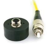
37 MS12 Return Loss Module Product Description The MS12 Return Loss Module combines advanced time-domain technology with a built in unique wide aperture integrating cavity. An internal monitoring feature maintains laser stability for reliable insertion loss testing throughout an entire working day. The internal return loss reference helps with highly accurate multimode and single-mode return loss measurement performance. The multimode MS12 Return Loss Meters meet IEC Encircled Flux Standard. The IQS-3250B and IQS-9403 are fully compatible with the MS12001 line. They meet the same specifications and will be recognized by both the MS12001 and the IQS-12001B systems. KEY FEATURES SM 1310, 1490, 1550 and 1625 nm MM 850, 1300 nm RL: SM 80 db RL: MM 50 db Integrating Cavity (9 mm) Power Meter Detector APPLICATIONS Component testing Connector and Patchcord testing Incoming inspection QA Testing COMPLIANCE Multimode meets IEC Encircled Flux standard IN THE BOX Return Loss Meter Calibration Certificate Detector Cap FC Detector Adapter Hybrid Test Jumper SM comes with power level Adjustment Jumper 37
38 Accurate, Repeatable and Flexible The wide aperture of the unique integrating cavity used on the MS12 modules makes it usable both for simplex and multi-channel connectors and make the connector alignment much less critical. The other big advantage of the integrating cavity used is the negligible polarization dependence. Therefore, accuracy and repeatability of the measurements are increased. Remote head cavity option available for additional measurement flexibility. The integrating cavity is a standard feature of all modules used in the MS12001 system, the loss test modules and the loss meters. Based on advanced time domain technology and the wide aperture integrating cavity detector, the MS12 IL/RL Loss Meter module will deliver accurate and repeatable insertion loss and return loss measurements. The internal monitoring channel ensures accurate insertion loss measurements by compensating for any source power variations. The insertion loss measurement has been developed in accordance with the TIA/EIA A Standard FOTP-34A, Interconnection Device Insertion Loss Test. Ordering Scheme Single-Mode Version MS FA Single-mode version comes with FC/APC output connector LASER 1 LASER 2 DETECTOR No Laser 1310nm 1490nm No Laser 1550nm 1625nm Front Panel Leave Blank Remote Head R Multimode Version MS FIBER TYPE FP DETECTOR The standard multimode versions contain two lasers at 850 and 1300 nm and comes with an FC/UPC output connector 50/125 µm 62.5/125 µm Front Panel Leave Blank Remote Head R 38 JGR Optics Inc. 160 Michael Cowpland Dr. Ottawa, Ontario K2M 1P6 CANADA T F info@jgroptics.com
39 Specifications OPTICAL / ELECTRICAL SPECIFICATIONS Parameter Specification Single-mode Multimode Fiber Type (μm) 9/125 50/125 or 62.5/125 Encircled Flux Standard N/A IEC Operating Wavelengths (nm) 1310 / 1550 or 1490 / 850/ Insertion Loss Uncertainty (db) ± / Insertion Loss Stability (db) 1 ± ± 0.01 Return Loss (db) 30 to to 50 ± 1.0 (30 to 70) ± 1.2 (10 to 30) Return Loss Accuracy (db) ± 1.7 (70 to 75) ± 1.5 (30 to 40) ± 2.2 (75 to 80) ± 1.6 (40 to 43) ± 2.9 (43 to 50) Return Loss Repeatability (db) 2 ± 0.1 (30 to 65) ± 0.2 (10 to 30) ± 0.2 (65 to 70) ± 0.4 (30 to 40) ± 0.4 (70 to 75) ± 0.6 (40 to 43) ± 1.5 (75 to 80) ±1.8 (43 to 50) Testing Time (s) < 6 Cable Assembly Length (m) 1.7 to 1500 Detector Type Integrating cavity Test Method End to end / bidirectional Notes: 1 For a stable connection over a period of 15 minutes. 2 For a stable connection over 10 measurements. MECHANICAL / ENVIRONMENTAL SPECIFICATIONS Parameter Specification Number of slots 2 Unit Dimensions W x H x D (cm) 7.4 x 12.5 x 28.2 Shipping Box Dimensions W x H x D (cm) 43 x 27 x 47 Unit Weight (kg) 0.9 Total Shipment Weight (kg) 1.5 (depending on number of modules purchased) Operating Temperature ( C) 0 to 40 Storage Temperature ( C) 40 to 60 Humidity (Non-condensing) Maximum 80%, no condensing at 40 39


40 MS12-PM Power Meter Module Product Description The MS12-PM Power Meter features a unique wide-aperture cavity, also known as integrating sphere technology. The MS12-PM is an economical solution providing excellent linearity, surface uniformity, wide area and repeatable connection loss, even with changing adapters. The MS12-PM is flexible modular power meter with fast response time and is compatible with angled and non-angled polishes. It also provides low polarization dependence. KEY FEATURES Uses the same cavity as Return Loss Meters Replacement for IQS-9403 APPLICATIONS Simplex and Multifiber for highthroughput applications IN THE BOX Power Meter Detector Cap FC Detector Adapter Ordering Scheme MS12-PM01 Power Meter 40 JGR Optics Inc. 160 Michael Cowpland Dr. Ottawa, Ontario K2M 1P6 CANADA T F info@jgroptics.com
41 Specifications OPTICAL/ELECTRICAL SPECIFICATIONS Parameter Detector Type Specification Single-mode Multimode Integrating Cavity Insertion Loss Uncertainty (db) ± / Insertion Loss Stability (db) 2 ± ± 0.01 MECHANICAL / ENVIRONMENTAL SPECIFICATIONS Parameter Specification Number of slots 1 Unit Dimensions W x H x D (cm) 3.6 x 12.5 x 28.2 Shipping Box Dimensions W x H x D (cm) 43 x 27 x 47 Unit Weight (kg) 0.8 Total Shipment Weight (kg) 1.4 (depending on number of modules purchased) Operating Temperature ( C) 0 to 40 Storage Temperature ( C) 40 to 60 Humidity (Non-condensing) Maximum 80%, no condensing at 40 41


42 MS7 Optical Switch Module Product Description The MS7 optical switches are available in a variety of configurations from 2x2, 1x2 to 1x72 for both single-mode and multimode fibers. They provide the flexibility required to configure the MS12001 system to support various applications like multiwavelength testing, multifiber connector testing or high-throughput configurations. EXCLUSIVE TO JGR The MS7 modular optical switches provide high performance at a reasonable cost and are exclusive to JGR for use in the MS12001 cable assembly and component test system. KEY FEATURES Configurations from 2x2, 1x2 up to 1x72 SM and MM RL: SM >60 db / MM >40 db IL 0.7 db Available with fixed connectors FC/APC or FC/UPC APPLICATIONS 4-wavelength, Multifiber and highthroughput applications IN THE BOX MS7 Switch Test Report 42 JGR Optics Inc. 160 Michael Cowpland Dr. Ottawa, Ontario K2M 1P6 CANADA T F info@jgroptics.com
43 Configuration Options; A R N 2 X 2 CROSS-OVER A Configuration - Single input, switched to any output 2X Configuration -Two inputs, switched straight through or crossover Ordering Scheme MS7-1A B OUTPUT SWITCH x2 1x4 1x12 1x24 1x32 1x48 1x72 FIBER TYPE /125μm 50/125μm 62.5/125μm CONNECTOR TYPE FP FA FC/UPC FC/APC MS7-2X B FIBER TYPE /125µm 50/125µm 62.5/125µm CONNECTOR TYPE FP FA FC/UPC FC/APC 43
44 Specifications OPTICAL / ELECTRICAL SPECIFICATIONS Parameter Specification 1x2, 2x2 1x4, 1x12, 1x24, 1x32, 1x48, 1x72 Single-mode Multimode Single-mode Multimode Wavelength Range (nm) / Insertion Loss (db) Return Loss (db) 1 > 50 > 35 > 60 > 40 PDL (db) 0.05 N/A 0.05 N/A Repeatability (random switching) (db) N/A +/ Repeatability (sequential) (db) ± 0.01 ± Crosstalk (maximum) (db) 80 Maximum Input Power (mw) 300 Switching Time (ms) Switch Life 10 8 cycles Notes: 1 Excluding connectors. MECHANICAL / ENVIRONMENTAL SPECIFICATIONS Specification Parameter 1x2, 2x2 1x4, 1x12 1x24 1x32, 1x48 1x72 Number of slots Unit Dimensions W x H x D (cm) 3.6 x 12.5 x x 12.5 x x 12.5 x x 12.5 x x 12.5 x 28.2 Shipping Box Dimensions W x H x D (cm) 43 x 27 x 47 Unit Weight (kg) Total Shipment Weight (kg) From 1 (depending on number of modules purchased) Operating Temperature ( C) 0 to 40 Storage Temperature ( C) 40 to 60 Humidity (Non-condensing) Maximum 80% RH at JGR Optics Inc. 160 Michael Cowpland Dr. Ottawa, Ontario K2M 1P6 CANADA T F info@jgroptics.com

45 MS4 Polarity Test Module Product Description The MS4 Polarity Tester is a simple, user-friendly module specifically designed to check the polarity of multi-fiber trunk cables. The MS4 can significantly improve throughput in a production environment where the possibility of process errors demands an efficient method to test and confirm the correct polarity. The MS4 supports testing of up to 48 fiber single-mode and multimode ribbon cables. Intuitive software quickly displays PASS/FAIL results for any ribbon configuration including type A, B, C, D and custom profiles. The MS4 can be paired with an MS12 Return Loss module inside one of the MS Mainframes to provide IL, RL & Polarity results in a single station using the MS12001 software. KEY FEATURES Simple Pass/Fail results Up to 48 channels in one module with the ability to expand to 432 channels Testing results can easily be exported to EXCEL MS12001 software & database integration APPLICATIONS MPO cable assembly testing Ribbon cable manufacturing QC Inspection IN THE BOX MS4 Polarity Test module USB power/data cable 45
46 Ordering Scheme MS4- -MA NUMBER OF CHANNELS channel 24-channel 48-channel Specifications OPTICAL / ELECTRICAL SPECIFICATIONS Parameter Specification Operating Wavelengths (nm) 650 Laser Class 2 Optics Interface Output MTP/MPO APC Male (SM) Input MTP/MPO UPC Male (MM) Detected Polarities A,B,C,D plus unlimited customizable mappings Test Time <2s IL Tolerance <6dB MECHANICAL / ENVIRONMENTAL SPECIFICATIONS Parameter Specification Number of slots 2 Unit Dimensions W x H x D (cm) 11.2 x 12.5 x 28.2 Shipping Box Dimensions W x H x D (cm) 43 x 27 x 47 Unit Weight (kg) 0.9 Total Shipment Weight (kg) From 1 (depending on number of modules purchased) Operating Temperature ( C) 0 to 40 Storage Temperature ( C) 40 to 60 Humidity (Non-condensing) Maximum 80% RH at JGR Optics Inc. 160 Michael Cowpland Dr. Ottawa, Ontario K2M 1P6 CANADA T F info@jgroptics.com


47 MS Mainframes Product Description The modular units of the Cable Assembly Test System can be powered using the MS05B/MS08B benchtop mainframes or the MS10R rackmount mainframe along with a customizable external computer*. The MS mainframes communicate to a computers via an included PCI card running on Windows 10, Windows 8, or Windows 7. The MS mainframes allow for both single-mode and multimode insertion loss and return loss testing within a single station. Different modular configurations can be setup for testing up to four wavelengths. Pairing an MS12 with an MS7 Optical Switch allows for multi-fiber testing in the single mainframe. Cascading mainframes or pairing with an external SX8 switch allows for higher channel count testing requirements. KEY FEATURES 5-slot, 8-slot, or 10-slot mainframes Controlled by an external computer* Compact Benchtop or Rackmount * See minimum requirement IN THE BOX MS05B, MS08B or MS10R PCI Card Power Cord 47
48 Ordering Scheme MS05B MS08B MS10R Specifications MINIMUM COMPUTER REQUIREMENTS Operating System 32-bit and 64-bit compatible - Windows 7 Case Size Mid-Tower Motherboard 1 available PCIe slot Hard Drive At least 40GB free Processor 2nd Generation Intel Core i3 or higher RAM 4GB MECHANICAL / ENVIRONMENTAL SPECIFICATIONS Parameter Specification MS05B MS08B MS10R Form factor Benchtop Rackmount Number of slots Unit Dimension W x H x D (cm) 36 x 15 x x 15 x x 44.5 x 13 Shipping Box Dimensions W x H x D (cm) 42 x 27 x x 32 x x 58 x 33 Unit Weight (kg) Total Shipment Weight (kg) Operating Temperature ( C) 0 to 40 0 to 40 0 to 40 Storage Temperature ( C) 40 to to to 70 Humidity (Non-condensing) Maximum 95% RH Maximum 95% RH Maximum 95% RH from 0 to 40 from 0 to 40 from 0 to JGR Optics Inc. 160 Michael Cowpland Dr. Ottawa, Ontario K2M 1P6 CANADA T F info@jgroptics.com
49 Backreflection Meters
.")
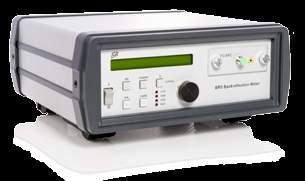
50 BR5 Backreflection Meter GMS Software Product Description The BR5 Backreflection Meter is a user-friendly instrument developed with extremely stable optics for precise measurement of backreflection, insertion loss and power. The BR5 features up to four built-in laser sources at wavelengths of 850, 1300, 1310, 1490, 1550, 1625 or 1650 nm (depending on fiber type). An intuitive display and keypad simplifies the collection and management of measurement data allowing quick access to the test results from various channels. The meter may be controlled through remote interface (GPIB, RS232, or USB*) or locally via the user-friendly front panel keypad and display. The BR5 achieves ultra-stable backreflection measurements at very low values with accuracy typically at ±0.4 db and measurement sensitivity is to 80dB. Insertion loss relative accuracy is ± 0.05dB. The BR5 can be used with our GMS software to help automate short and long term testing. All our BR5 meters come standard with our GMS Software at no additional cost. The multimode option of the BR5 meets IEC Encircled Flux Standard. *USB interface via-usb-db9 adapter KEY FEATURES Stable BR measurements at low values Up to 4 internal lasers BR range to 80 db User Friendly APPLICATIONS Component testing Connector and patchcord testing Incoming inspection QA testing COMPLIANCE MM meets IEC Encircled Flux Standard UL/CSA IEC FCC Part 15 (Class A) EN (Class A) IN THE BOX BR5 Meter AC power cord Calibration Certificate Calibrated Jumper Hybrid Test Jumper Detector Cap FC Detector Adapter MW3 Mandrel Wrap 50 JGR Optics Inc. 160 Michael Cowpland Dr. Ottawa, Ontario K2M 1P6 CANADA T F info@jgroptics.com
51 Specifications OPTICAL/ELECTRICAL SPECIFICATIONS Parameter Specification Single-mode Multimode Fiber Type (μm) (9/125) (50/125 or 62.5/125) Encircled Flux Standard N/A IEC Operating Wavelengths (nm) 1310 / 1490 / 1550 / 1625 / / 1300 Backreflection Range (db) 0 to 80 0 to 60 Backreflection Accuracy (db) 1,2 ± 0.4 Detector Type 2mm InGaAs / 5mm Ge Power Range (dbm) 0 to 80 / 0 to 60 Absolute Power Accuracy (db) 3 ± 0.25 Insertion Loss Accuracy (db) ± 0.05 (< 5 db loss) ± 0.15 (> 5 db loss) Remote Interface GPIB / RS232 / USB 4 Input Voltage V AC, Hz Power Consumption (VA) 60 maximum Display 16 character LCD Notes: 1 Add 0.1 db to the spec for every 1dB below 60dB (single-mode). 2 Add 0.1dB to the spec for every 1dB below 45dB (multimode). 3 Measured at 10 dbm. 4 SB interface via USB-DB9 adapter. MECHANICAL / ENVIRONMENTAL SPECIFICATIONS Parameter Specification Unit Dimensions W x H x D (cm) 26 x 11 x 26 Shipping Box Dimensions W x H x D (cm) 37 x 25 x 38 Unit Weight (kg) 3 Total Shipment Weight (kg) 4 Operating Temperature ( C) 0 to 40 Storage Temperature ( C) 40 to 60 Humidity (Non-condensing) Maximum 95% RH from 0 to 40 51

52 Ordering Scheme Single-Mode Version BR5- LASER 1 No Laser 1310 nm 0 3 LASER 3 No Laser 1550 nm FA DETECTOR TYPE 2mm InGaAs 5 mm Ge 2 5 DETECTOR Up to four lasers may be selected the single-mode version LASER 2 No Laser 1490 nm 0 4 LASER 4 No Laser 1625 nm 1650 nm Front Panel Leave Blank Remote Head R Multimode Version BR FA DETECTOR TYPE 2mm InGaAs 5 mm Ge 2 5 FIBER TYPE 50/125 µm 62.5/125 µm DETECTOR Front Panel Leave Blank Remote Head R The standard multimode version contains two lasers at 850 and 1300 nm Other wavelengths are available upon request Additional accessories See Page JGR Optics Inc. 160 Michael Cowpland Dr. Ottawa, Ontario K2M 1P6 CANADA T F info@jgroptics.com
53 MBR5 Multi-Channel Backreflection Meter GMS Software Product Description The MBR5 Multi-Channel Backreflection Meter is an instrument developed with extremely stable optics for precise measurement of backreflection, insertion loss and power. Available with 4, 12, 24, 48 or 72, output channels, the MBR5 is a practical choice for both single fiber and multi fiber testing. The MBR5 features up to four built-in laser sources at wavelengths of 850, 1300, 1310, 1490, 1550, 1625 and 1650 nm (depending on fiber type), and can be configured for single-mode or multimode measurements. An intuitive display and keypad simplifies the collection and management of measurement data allowing quick access to the test results from various channels. The meter may be controlled through remote interface (GPIB, RS232, or USB*) or locally via the user-friendly front panel keypad and display. The MBR5 achieves ultra-stable backreflection measurements at very low values with accuracy typically at ±0.4 db and measurement sensitivity is to 80dB. In addition, the cavity option is particularly useful for multi-fiber connectors with large fiber counts. The MBR5 can be used with our GMS software to help automate short and long term testing. All our MBR5 meters come standard with our GMS Software at no additional cost. The multimode option of the MBR5 meets IEC Encircled Flux Standard. *USB interface via-usb-db9 adapter KEY FEATURES Stable BR measurements at low values Up to 72 output channels IL and BR measurements Up to 4 internal lasers APPLICATIONS Component testing Ribbon fiber testing Simultaneous testing with multiple connector types Incoming inspection QA testing COMPLIANCE MM meets IEC Encircled Flux Standard UL/CSA IEC IEC Class 1 FCC Part 15 (Class A) EN (Class A) IN THE BOX MBR5 Meter AC power cord Calibration Certificate Calibrated Jumper Hybrid Test Jumper Detector Cap FC Detector Adapter MW3 Mandrel Wrap 53
54 Ordering Scheme Single-Mode Version MBR5- OUTPUT CHANNELS 4-channel 12-channel 24-channel 48-channel 72-channel LASER 1 No Laser 1310 nm LASER 2 No Laser 1490 nm LASER 3 No Laser 1550 nm LASER 4 No Laser 1625 nm 1650 nm FA DETECTOR TYPE 2mm InGaAs 5 mm Ge Cavity 2 5 C Up to four lasers may be selected for the single-mode version DETECTOR Front Panel Leave Blank Remote Head R Multimode Version OUTPUT CHANNELS 4-channel 12-channel 24-channel 48-channel 72-channel MBR DETECTOR TYPE 5 mm Ge Cavity 5 C - FIBER TYPE 50/125 µm 62.5/125 µm CONNECTOR TYPE FC/APC FA DETECTOR Front Panel Leave Blank Remote Head The standard multimode version contains two lasers at 850 and 1300 nm Other wavelengths are available upon request R Short Wavelength Single-Mode Version MBR FA Up to 3 wavelengths may be selected of the same core size. LASER nm 3/125 µm 780nm 5/125 µm LASER nm 3/125 µm 1060nm 5/125 µm LASER nm 3/125 µm 940nm 5/125 µm DETECTOR R Front Panel Leave Blank Remote Head 54 JGR Optics Inc. 160 Michael Cowpland Dr. Ottawa, Ontario K2M 1P6 CANADA T F info@jgroptics.com
55 Additional accessories See Page 61 55
56 Specifications OPTICAL / ELECTRICAL SPECIFICATIONS Parameter Specification Single-mode Short Wavelength Single-mode Multimode Fiber Type (μm) 9/125 3/125 5/125 50/ /125 Encircled Flux Standard N/A IEC Operating Wavelengths (nm) 1310 / 1490 / 450 / 520 / 780 / 940 / 1550 / 1625 / / 1300 Backreflection Range (db) 0 to 80 0 to 60 0 to 60 Backreflection Accuracy (db) 1,2 ± 0.4 Detector Type 2 mm InGaAs / 3mm Si / 5mm Ge / Cavity Power Range (dbm) 0 to 80 0 to to 60 0 to 40 Absolute Power Accuracy (db) 3 ± 0.25 Relative Power Accuracy (db) ± 0.05 (< 5 db loss) ± 0.15 (> 5 db loss) Remote Interface GPIB / RS232 / USB 4 Input Voltage V AC, Hz Power Consumption (VA) 80 maximum Display 4 lines, 16 character per line, LCD Notes: 1 Add 0.1 db to the spec for every 1dB below 60dB (single-mode). 2 Add 0.1dB to the spec for every 1dB below 45dB (multimode). 3 Measured at 10 dbm. 4 SB interface via USB-DB9 adapter. MECHANICAL / ENVIRONMENTAL SPECIFICATIONS Parameter Specification Unit Dimensions W x H x D (cm) 36 x 15 x 34 Shipping Box Dimensions W x H x D (cm) 43 x 27 x 47 Unit Weight (kg) 7 Total Shipment Weight (kg) 8 Operating Temperature ( C) 0 to 40 Storage Temperature ( C) 40 to 60 Humidity (Non-condensing) Maximum 95% RH from 0 to JGR Optics Inc. 160 Michael Cowpland Dr. Ottawa, Ontario K2M 1P6 CANADA T F info@jgroptics.com

57 PDL5 Polarization Dependent Loss Meter GMS Software Product Description The PDL5 PDL/IL/BR Multimeter is built on top of stable and proven MBR5 meter technology and is taken to the next level. Improved source isolation, electronics, optics, and continuous laser power referencing enhance the performance to allow for repeatable and stable measurements. The meter is capable of providing facilities with the PDL, IL and average loss with up to db as well as a backreflection resolution of 0.1 db. The PDL5 is a practical choice for many types of fiber optical component testing. It is available with up to 4 internal sources (1310/1490/1550/1625/1650 nm), calibrated external inputs, or multiple detectors. An intuitive display and keypad simplifies the collection and management of measurement data allowing quick access to the test results from various channels. The meter may be controlled through remote interface (GPIB, RS232, or USB*) or locally via the user-friendly front panel keypad and display. The PDL5 and GMS Software can be used paired with an SX8 switch. All our PDL5 meters come standard with our GMS Software at no additional cost. *USB interface via-usb-db9 adapter KEY FEATURES Ultra Stable and Accurate PDL, IL ave. loss and BR measurements Up to 4 Internal Lasers Up to 2 Output Channels or 2 Detectors 4 or 6 states Mueller matrix methods Resolution down to db ~1 second PDL Measurements APPLICATIONS Optical Component Testing Incoming Inspection QA Testing COMPLIANCE UL/CSA IEC IEC Class 1 FCC Part 15 (Class A) EN (Class A) IN THE BOX PDL5 Meter AC Power Cord Calibration Certificate Calibrated Jumper Hybrid Test Jumper Detector Cap FC Detector Cap MW3 Mandrel Wrap 57
58 The PDL5 meter achieves typical PDL accuracy down to ±0.005 db and average loss and IL accuracy down to ±0.05 db. The meter achieves ultrastable backreflection measurements at very low values. Accuracy is typically ±0.4 db and measurement sensitivity is to 75 db. *USB interface via USB-DB9 adapter Ordering Scheme PDL FA OUTPUT CHANNELS LASER 1 LASER 3 DETECTOR TYPE DETECTOR 1-channel 2-channel No Laser 1310 nm LASER No Laser 1550 nm LASER mm InGaAs 5 mm Ge Cavity 2 5 C Front Panel Leave Blank Remote Head NUMBER OF DETECTORS R No Laser 1490 nm 0 4 No Laser 1625 nm 1650 nm INPUT None Leave Blank External E 1 Detector Leave Blank 2 Detectors 2 *Additional options may be available upon request 58 JGR Optics Inc. 160 Michael Cowpland Dr. Ottawa, Ontario K2M 1P6 CANADA T F info@jgroptics.com
59 Specifications OPTICAL / ELECTRICAL SPECIFICATIONS Parameter Specification Fiber Type (μm) SMF-28e (9/125) Operating Wavelengths (nm) 1310 / 1490 / 1550 / 1625 / 1650/ Ext Detector Type 2mm InGaAs 5mm Ge Power Range (dbm) 5 to to -60 PDL Accuracy /-(0.005dB + 2% of PDL) +/-(0.010dB + 2% of PDL) 1310/1490/1625/1650 +/-(0.010dB + 2% of PDL) +/-(0.015dB + 2% of PDL) PDL Calculation method Mueller Matrix PDL Dynamic Range (db) 0 to 3 Absolute Power Accuracy (db)¹ +/-0.25 Relative Power Accuracy (db) +/-0.05 PDL Measurement time (s)² 0.7 Backreflection Range (db) 0 to -75 Backreflection Accuracy (db)³ 0.4 Remote Interface GPIB / RS-232 / USB 4 Input Voltage V AC, Hz Power Consumption (VA) 80 maximum Display 4 lines, 16 character per line, LCD Notes: 1 Measured at 10 dbm. 2 4-state mode. 1.2s in 6 state mueller matrix mode. 3 Add 0.1 db to the spec for every 1dB below 60dB. 4 USB interface via USB-DB9 adapter. MECHANICAL / ENVIRONMENTAL SPECIFICATIONS Parameter Specification Unit Dimensions W x H x D (cm) 36 x 15 x 34 Shipping Box Dimensions W x H x D (cm) 43 x 27 x 47 Unit Weight (kg) 9 Total Shipment Weight (kg) 10 Operating Temperature ( C) 0 to 40 Storage Temperature ( C) 40 to 60 Humidity (Non-condensing) Maximum 95% RH from 0 to 40 59

60 Polarity Testing

61 PT5 Polarity Tester Product Description The PT5 Polarity Tester is a simple, user-friendly instrument specifically designed to check the polarity of multi-fiber trunk cables. The PT5 can significantly improve throughput in a production environment where the possibility of process errors demands an efficient method to test and confirm the correct polarity. The PT5 supports testing of up to 72 fiber single-mode and multimode ribbon cables. Intuitive software quickly displays PASS/FAIL results for any ribbon configuration including type A, B, C and custom profiles. Testing can be performed through the included software package which enables management of unlimited custom cable types and the ability to export test results to Microsoft Excel. The software also provides access to a Visual Fault Locator mode which enables easy identification of any damaged fiber. KEY FEATURES Simple Pass/Fail results Up to 72 channels in one box with the ability to expand to 432 channels Testing results can easily be exported to EXCEL APPLICATIONS MPO cable assembly testing Ribbon cable manufacturing QC Inspection IN THE BOX PT5 Polarity Tester USB power/data cable Polarity Test Software and drivers 61 JGR Optics Inc. 160 Michael Cowpland Dr. Ottawa, Ontario K2M 1P6 CANADA T F info@jgroptics.com
62 Ordering Scheme PT5- -MA CHANNELS 12-channel 24-channel 48-channel 72-channel Specifications OPTICAL / ELECTRICAL SPECIFICATIONS Parameter Specification Operating Wavelengths (nm) 650 Laser Class 2 Optics Interface Output MTP/MPO APC Male (SM) Input MTP/MPO UPC Male (MM) Remote Interface USB 2.0 Detected Polarities A,B,C plus unlimited customizable mappings Test Time <2s IL Tolerance <6dB Communication & Charge USB 2.0, charging up to 1A MECHANICAL / ENVIRONMENTAL SPECIFICATIONS Parameter Specification Unit Dimensions W x H x D (cm) 26 x 11 x 26 Shipping Box Dimensions W x H x D (cm) 37 x 25 x 38 Unit Weight (kg) 3 Total Shipment Weight (kg) 4 Operating Temperature ( C) 0 to 40 Storage Temperature ( C) 40 to 60 Humidity (Non-condensing) Maximum 95% RH from 0 to 40 62
63 Inspection
64 CS Inspection Scopes Product Description The benchtop CS Inspection Scopes utilize coaxial illumination to provide users with a critical view of fine scratches ideal for post polish, component assembly and QC inspection of fiber connectors. The CS Inspection scope is available in 200x or 400x magnification. The workstation includes a video microscope, video monitor and a 2.5 mm universal adapter. KEY FEATURES Clear display Interchangeable adapters Economical 200x or 400x magnification APPLICATIONS Factory post-polish Component assembly QC inspections of fiber connectors IN THE BOX CS Inspection Scope Video Monitor AC power cable 2.5mm universal adapter 1.25mm universal adapter 64 JGR Optics Inc. 160 Michael Cowpland Dr. Ottawa, Ontario K2M 1P6 CANADA T F info@jgroptics.com


65 Accessories STANDARD ACCESSORIES In addition to the standard accessories provided with your meter, JGR offers additional accessories including a variety of detector adaptors and remote heads to enhance your testing capability. ADDITIONAL ACCESSORIES Detector Adapters JGR offers a comprehensive line of detector adapters for a variety of fiber types and applications. Manufactured with precision to ensure repeatable ferrule positioning and reliable performance, JGR Detector Adapters are indispensable test instrument accessories. Customized Solutions In addition to our standard products, JGR offers detector adapters tailored to your particular requirements. Remote head The JGR 5 mm and cavity remote heads offer flexibility in testing setup so that measurements may be taken at a distance from the measuring meter. 65 JGR Optics Inc. 160 Michael Cowpland Dr. Ottawa, Ontario K2M 1P6 CANADA T F info@jgroptics.com


 DA120 Barrel")


66 Accessories (cont d) Detector adapters For JGR Detector Barrels and new Cavity Detector. DA100 Detector Cap DA101 FC Detector Adapter DA102 ST Detector Adapter DA103 SC Detector Adapter DA109 SMA905 Detector Adapter DA112 MT Detector Adapter DA114 MU Detector Adapter DA115 E2000 Detector Adapter DA1418 Universal 1.25 mm Detector Adapter(LC/MU) DA113 Multiple Fiber Holder (Bare Ribbon Fiber Adapter) DA120 Barrel Detector Adapter To be used with DA113 DA113 + DA120 ASSEMBLY EXAMPLE DA116 Universal 2.5 mm Detector Adapter (FC/SC/ST) DA117 MTP/MPO Detector Adapter DA118 LC Detector Adapter DA119 MT-RJ Detector Adapter 66


67 Accessories (cont d) DA122 MPX Detector Adapter DA123 Motherboard MT Detector Adapter DA124 Universal 2.0 mm Detector Adapter DA126 Universal 1.6 mm Detector Adapter DA128 Tri-LC Detector Adapter DA135 Optitap Detector Adapter DA140 Barrel Detector Adapter To be used with DA141/ DA143 DA141 Fusion Splice Holder Furukawa S199 DA143 Fusion Splicer Holder Sumitomo type-65m8 DA229 Optitip Detector Adapter DA320 JGR Threads Barrel for BFA3000 BFA3000 Universal Single Bare Fiber Adapter To be used with DA JGR Optics Inc. 160 Michael Cowpland Dr. Ottawa, Ontario K2M 1P6 CANADA T F info@jgroptics.com


68 Accessories (cont d) Miscellaneous MS-TJ MS12 power level adjustment jumper: 100/140um, FC/APC-FC/UPC NTT Index Matching Block MW3 Mandrel Wrap USB to Serial (DB-9) Adapter RS232 to Ethernet Converter 68
69 Repair and Calibration AT JGR WE ARE COMMITTED TO ACCURATE AND TIMELY CALIBRATION AND REPAIR SERVICES TRACEABLE TO NIST AND ACCORDING TO THE HIGHEST STANDARDS IN THE INDUSTRY. CALIBRATION We are experienced in handling a wide range of fiberoptic test equipment requirements. We offer calibration services traceable to NIST. and conforming to the general requirements for the Laboratory Accreditation ISO In addition our Calibration Laboratory is accredited specifically for calibration of fiberoptic test equipment. WHY CALIBRATE? Calibration ensures that your measurement devices are operating within their specifications and that the measurements they perform are traceable to NIST Standards - an important requirement if you (or your customer) require precision and traceability. ISO 17025:2005 LABORATORY ACCREDITATION JGR recognizes the importance of quality in all aspects of our business. We operate an ISO17025:2005 Accredited Laboratory to ensure quality standards for customer care and technical services. This accreditation is a testament to our commitment to quality and our demonstrated proficiency in calibration services. It ensures that we are continually evaluating and improving our services. NIST-TRACEABLILITY NIST-traceability means that your instrument s measurements are connected through an unbroken chain to National Institute of Standards and Technology measurements. JGR ensures this traceability by regularly calibrating our instruments at the NIST labs. 69 JGR Optics Inc. 160 Michael Cowpland Dr. Ottawa, Ontario K2M 1P6 CANADA T F info@jgroptics.com
70 JGR OPTICS INC. 160 Michael Cowpland Drive Ottawa, Ontario K2M 1P6 CANADA Sales / Technical Support / ext. 248 Fax: info@jgroptics.com


71 JGR S INNOVATIVE SOLUTIONS 2007 Introduction of MBR5 Multi-Channel Backreflection Meter 2006 Introduction of Industry-leading BR5 Backreflection Meter 2009 ISO accreditation of calibration lab 2011 Acquisition of EXFO s IQS-12001B and launch of MS12001 Cable Assembly Test System 2013 Introduction of PDL5 Polarization Dependant Loss Meter Introduction of MS05B Benchtop Mainframe 2012 Introduction of OA5 Programmable Variable Attenuators Introduction of CS400K Inspection Scope 2014 Introduction of TLS5 Tunable Laser Source 2015 Introduction of MS08B Benchtop Mainframe 2016 Introduction of PT5 Polarity Tester 2017 Introduction of MS4 Polarity Test module Introduction of EOTS Environmental Optical Test System 2018 Introduction of O, E, S & CL band TLS Introduction of WCS Wide Component Test system 2018 Introduction of SX1 MEMS Switch Introduction of OA1 MEMS Attenuator
Cable Assembly Test System. MS12001 System
 Cable Assembly Test System KEY FEATURES MS10P is a powerful controller unit with 10 slots MS10E Expansion Chassis for up to 10 extra slots Remote control via Ethernet/GPIB card Turn-key software Local
Product Catalog Fiberoptic Instrumentation JGR
 Product Catalog Fiberoptic Instrumentation JGR Table of Contents INTRODUCTION Corporate Overview. 4 PRODUCTS TUNABLE LASERS TLS Tunable Laser Source. 5 USB MAINFRAME UM08 USB Mainframe.. 7 UM05 Optical
Product Catalog Fiberoptic Instrumentation
 Product Catalog Fiberoptic Instrumentation optical switches JGR cable assembly test system accessories repair and calibration Table of Contents INTRODUCTION Corporate Overview. 4 PRODUCTS OPTICAL SWITCHES
Cable Assembly Test System
 Cable Assembly Test System KEY FEATURES MS05P & MS10P are powerful controller units with 5 or 10 slots MS10E Expansion Chassis for up to 10 extra slots Remote control via Ethernet/GPIB card MS05P features
Optical Component Environmental Test System OCETS Plus Series
 COMMUNICATIONS TEST & MEASUREMENT SOLUTIONS Optical Component Environmental Test System OCETS Plus Series Key Features High Return Loss option (HiRL) monitors RL up to 70 db Up to 210 device channels (420
IQS-12001B CABLE ASSEMBLY AND COMPONENT TEST SYSTEM. Telecom Test and Measurement
 CABLE ASSEMBLY AND COMPONENT TEST SYSTEM IQS-12001B R&D AND MANUFACTURG OPTICAL Provides the most accurate insertion loss and reflectance measurements on the market for components and cable assemblies
MAP Insertion Loss/Return Loss Meter (morl-a1 with PCT Automation Software)
") COMMUNICATIONS TEST & MEASUREMENT SOLUTIONS MAP Insertion Loss/Return Loss Meter (morl-a1 with PCT Automation Software) Key Features Mandrel-free optical return loss measurements on fiber-optic patch-cords
COMMUNICATIONS TEST & MEASUREMENT SOLUTIONS MAP Insertion Loss/Return Loss Meter (morl-a1 with PCT Automation Software) Key Features Mandrel-free optical return loss measurements on fiber-optic patch-cords
Specialized Solutions for Fiber Optic Testing
 Specialized Solutions for Fiber Optic Testing www.optotest.com 1.805.987.1700 OP740 High-Speed Multichannel Optical Power Meter The OP740 offers a state-of-the-art solution for highspeed optical power
FTBx-1750/OHS-1700 KEY FEATURES RELATED PRODUCTS AND ACCESSORIES SPEC SHEET HIGH-PERFORMANCE POWER METER AND OPTICAL HEAD SERIES
 HIGH-PERFORMANCE POWER METER AND OPTICAL HEAD SERIES Fast, accurate, flexible power measurement in a platform-based solution. SPEC SHEET KEY FEATURES One, two or four detectors on a single module Ultra-High-Power
Agilent Lightwave Solution Platform
 Agilent Lightwave Solution Platform Configuration Guide May 2005 This guide provides configuration details for the Agilent 816xB family of mainframes and modules, including options and accessories. 8163B
MAP-200-Based Insertion Loss/ Return Loss Testing Solution
 MAP-200-Based Insertion Loss/ Return Loss Testing Solution morl/mil with PCT Application Environment Optical connectivity solutions (optical connectors, structured cabling, splitters, and the enclosures
KI 2400/2800 SERIES HAND HELD FIBER SOURCE FEATURES. kingfisher.com.au. OPTICAL COMMUNICATIONS TEST APPLICATIONS (in combination with a power meter)
") OPTICAL COMMUNICATIONS TEST APPLICATIONS (in combination with a power meter) Mixed single mode & multimode loss testing to 6 λ Multi-Fiber continuity & polarity testing Encircled Flux compliant testing
OPTICAL COMMUNICATIONS TEST APPLICATIONS (in combination with a power meter) Mixed single mode & multimode loss testing to 6 λ Multi-Fiber continuity & polarity testing Encircled Flux compliant testing
MBR5 Multi-Output Backreflection Meter
 MBR5 Multi-Output Backreflection Meter User Manual All information contained herein is believed to be accurate and is subject to change without notice. No responsibility is assumed for its use. JGR Optics
OTS-600 Series Optical Sources, Meters, Testers and Kits with Data Storage Capabilities
 features and benefits Large LCD screen and soft key menus Source and meter in one unit Auto wavelength switching and detection USB data ports OTS-600 Series Light Source and Power Meter Photo LAN1193 Ease
MS12001 Cable Assembly Test System. User Guide
 MS12001 Cable Assembly Test System User Guide Copyright 2011 JGR Optics Inc. All rights reserved. No part of this publication may be reproduced, stored in a retrieval system or transmitted in any form,
PREMIUM GRADE PATCHCORD / PIGTAIL
 01 Go4Fiber provides the broadest choice of patchcords and pigtails to the industry including LC, SC, FC, ST, E2000 with Ultra-polished (UPC), Angle-Polished (APC) or other polish requirement. With our
PREMIUM GRADE PATCHCORD / PIGTAIL
 01 Go4Fiber provides the broadest choice of patchcords and pigtails to the industry including LC, SC, FC, ST, E2000 with Ultra-polished (UPC), Angle-Polished (APC) or other polish requirement. With our
OTS-400 Series Optical Meters, Sources and Testers A LANscape Solutions Product
 OTSK-4MDSD Specs Provided by www.aaatesters.com OTS-400 Series Applications Installation, testing and troubleshooting of LAN, telco, CATV and FTTx networks Description The OTS-400 Series of intelligent
ARIADROP: Fiber to the MDU (FTTM)
") DROP: Fiber to the MDU (FTTM) 05 Issue BECAUSE PERFORMANCE MATTERS DROP: Fiber to the MDU (FTTM) DROP DS-BS- 04/07/05 Overview Technologies DROP System is designed to provide both labor and material savings
DROP: Fiber to the MDU (FTTM) 05 Issue BECAUSE PERFORMANCE MATTERS DROP: Fiber to the MDU (FTTM) DROP DS-BS- 04/07/05 Overview Technologies DROP System is designed to provide both labor and material savings
Telecommunication Products
 Telecommunication Products Media Converters Couplers / Splitters WDM CWDM Telecommunication Products Media Converters The media converter is the most economical way to deploy fibre into your network. This
Master Oscillator Power Amplifier SLD System MOPA-SLD-850
 Master Oscillator Power Amplifier SLD System MOPA-SLD-850 1. Product Description The Superlum MOPA-SLD-850 is an ultra-high power SLD-based light source that features an extremely weak sensitivity to optical
OTS-400 Series Optical Sources, Meters, Testers and Kits with Data Storage Capabilities A LANscape Solutions Product
 Applications Testing and troubleshooting of various telecommunication networks Description The Corning Cable Systems OTS-400 Series of intelligent and versatile optical meters, sources and testers offers
Optical Splitter for Telecommunication Networks
 Introduction: Optical PLC splitter is a passive optical component which have a significant impact on the efficiency of communication network roll-outs especially in FTTx deployment. The incorporation of
PLC Products. Dr. K.R.Suresh Nair
 PLC Products Dr. K.R.Suresh Nair 2 Summary Established in 2005 Technical support from Hitachi, Japan FTTH splitters (1xN, 2xN where N=4,8,16,32,64) Capacity of 30K per annum Automated performance testing
HIGH DENSITY DATA CENTER CABLING GUIDE. Optics DACs Cables Cable Management Fiber TAPs Media Converters
 HIGH DENSITY DATA CENTER CABLING GUIDE Optics DACs Cables Cable Management Fiber TAPs Media Converters PROVIDING MTP CABLING SOLUTIONS FOR THE SMART DATA CENTER. APPROVED NETWORKS SETS THE STANDARD The
LightMUX. Passive Optical Networking
 PORTFOLIO OVERVIEW LightMUX LightMUX Passive Optical Networking Optelian FTTx/PON splitters and wavelength division multiplexers (WDMs) make the distribution of triple-play (voice, data, and video) traffic
FiberBasix 50 Handheld Testers
 SERIES COMPRISING THE ELS-50 LIGHT SOURCE AND EPM-50 POWER METER 2011 GLOBAL PORTABLE FIBER OPTIC TEST EQUIPMENT MARKET SHARE LEADERSHIP AWARD The ultimate CD/PMD characterization solution. Delivering
Artisan Technology Group is your source for quality new and certified-used/pre-owned equipment
 Artisan Technology Group is your source for quality new and certified-used/pre-owned equipment FAST SHIPPING AND DELIVERY TENS OF THOUSANDS OF IN-STOCK ITEMS EQUIPMENT DEMOS HUNDREDS OF MANUFACTURERS SUPPORTED
Planar Lightwave Circuit (PLC) Splitter, 1x4, 1x8, 1x12 and 1x16 Configurations in PEACOC Flexible Tray
 Splitter, 1x4, 1x8, 1x12 and 1x16 Configurations in PEACOC Flexible Tray") FEATURES: Telcordia GR-1221 Compliant Patented accessibility; easy, fast and accurate Low Insertion Loss Up to 24 simplex LC connectors per tray or 12 SC Simplex Connector Excellent Uniformity Low PDL
FEATURES: Telcordia GR-1221 Compliant Patented accessibility; easy, fast and accurate Low Insertion Loss Up to 24 simplex LC connectors per tray or 12 SC Simplex Connector Excellent Uniformity Low PDL
ConnectorMax MPO Link Test Solution A COMPLETE MPO POLARITY, CONTINUITY AND CONNECTOR INSPECTION SOLUTION FOR SHORT FIBER LINKS (UP TO 5 KM)
") A COMPLETE MPO POLARITY, CONTINUITY AND CONNECTOR INSPECTION SOLUTION FOR SHORT FIBER LINKS (UP TO 5 KM) All-in-one, easy-to-use solution to validate the polarity type, continuity and connector cleanliness
A COMPLETE MPO POLARITY, CONTINUITY AND CONNECTOR INSPECTION SOLUTION FOR SHORT FIBER LINKS (UP TO 5 KM) All-in-one, easy-to-use solution to validate the polarity type, continuity and connector cleanliness
FIBER PIGTAILED ULTRA STABLE LASER MODULE OZ-1000, OZ-2000 & OZ-3000 SERIES. Preliminary
 219 Westbrook Rd, Ottawa, ON, Canada, K0A 1L0 Toll Free: 1-800-361-41 Tel:(613) 831-0981 Fax:(613) 836-089 E-mail: sales@ozoptics.com FIBER PIGTAILED ULTRA STABLE LASER MODULE OZ-00, OZ-2000 & OZ-3000
OTEB-CO-P PRE-AMP EDFA INSTRUCTION MANUAL
 OTEB-CO-P PRE-AMP EDFA INSTRUCTION MANUAL Phone: (209) 586-1022 (800) 545-1022 Fax: (209) 586-1026 E-Mail: salessupport@olsontech.com www.olsontech.com 025-000521 Rev. X1 10/01/2012 SAFETY WARNINGS LASER
IQS-600. Optical, transport and datacom testing in a single platform environment INTEGRATED QUALIFICATION SYSTEM
 INTEGRATED QUALIFICATION SYSTEM R&D AND MANUFACTURING TESTING Optical, transport and datacom testing in a single platform environment Open architecture providing the power and flexibility to run automation
Passive Optical Components An Evolant Solutions Product
 Description offers a full line of passive optical component products that is specially designed for our complete fiber optic hardware portfolio to allow maximum network flexibility. Available components
Introduction to WaveSmart Optical Components
 Introduction to WaveSmart Optical Components Clearfield delivers unparalleled fiber performance with its WaveSmart optical components - custom built for the unique light requirements and interoperability
Optical Fiber Systems. Optical Fiber. Premise Connectivity Systems S Y S T E M S
 Premise Connectivity Systems Optical Fiber S Y S T E M S w w w. s i g n a m a x. c o m High-Density Rack-Mount Optical Fiber Enclosures Rack-Mount Optical Fiber Distribution Enclosures Rack-Mount Optical
Grid tunable laser source, Optical power meter, Optical attenuator, Optical switch, etc.
 Multi Application Test System AQ2200Series Multi Application Test System Ideal Measurement Solution for Optical Devices and Optical Transmission Systems A broad lineup of measurement modules Grid tunable
Multiple Application Platform MAP-200
 COMMUNICATIONS TEST & MEASUREMENT SOLUTIONS Multiple Application Platform MAP-200 Key Benefits Available in three mainframe configurations GPIB- and LXI-compliant (Ethernet) Optional 10.4-inch touch-screen-display
IQS-500 THE INTELLIGENT TEST SYSTEM. Telecom Test and Measurement
 THE INTELLIGENT TEST SYSTEM IQS-500 R&D AND MANUFACTURING OPTICAL Integrated test solutions for manufacturing, automation, optical qualification and R&D. Telecom Test and Measurement Intelligent Test and
Multiple Application Platform MAP-200
 COMMUNICATIONS TEST & MEASUREMENT SOLUTIONS Multiple Application Platform MAP-200 MAP-230 (top) and MAP-280 (bottom) mainframes Key Features Available in three mainframe configurations GPIB- and LXI-compliant
PLC SPLITTER PRODUCTS
 PLC SPLITTER PRODUCTS PLC Splitter Products FIBER OPTIC PRODUCTS PLC SPLITTER PRODUCTS Professional on providing complete, high-performance Optic Communication Components and Premise Distribution Solutions
BR5 Backreflection Meter
 5 Backreflection Meter User Manual All information contained herein is believed to be accurate and is subject to change without notice. No responsibility is assumed for its use. JGR Optics Inc, 2011. IN
T-BERD /MTS-4000 Platform Multiple Services Test Platform
 COMMUNICATIONS TEST & MEASUREMENT SOLUTIONS T-BERD /MTS-4000 Platform Multiple Services Test Platform Key Features Cost-effective, dual-modular and handheld platform Large 7-inch display (touchscreen option)
VE883. 4K HDMI Optical Extender (K1, MM) / 10km (K2, SM))
 / 10km (K2, SM))") VE883 4K HDMI Optical Extender (4K@300m (K1, MM) / 10km (K2, SM)) The VE883 is a fiber-based extender designed to extend uncompressed 4K signal up to 300 m (using VE883K1) or 10 km (using VE883K2) over
VE883 4K HDMI Optical Extender (4K@300m (K1, MM) / 10km (K2, SM)) The VE883 is a fiber-based extender designed to extend uncompressed 4K signal up to 300 m (using VE883K1) or 10 km (using VE883K2) over
MTP/MPO Cable Assemblies
 MTP/MPO Cable Assemblies MTP cable assemblies are multi-fiber patch cords suitable for high-density back plane and PCB solutions. MTP brand Fan-Out, Interconnect and Trunk cable offer up to 36 times the
LTS-2A LTS-10 LTS-10C LTS-11 LTS-12
 Optical Loss Test Kits LTS-2A LTS-10 LTS-10C LTS-11 LTS-12 Description Fit your application to your budget. Our Optical Loss Test Kits, and Fiber Test Kits combine the dependability and accuracy of our
VCL-TP, Teleprotection Equipment With Trip Counter Display Panel
 VCL-TP, Teleprotection Equipment With Trip Counter Display Panel Data Sheet Copyright: Valiant Communications Limited. 2008-2014 1 Product Overview VCL-TP, Teleprotection Equipment is an extremely reliable
A Division of Castle Microwave. Fibre Products.
 A Division of Castle Microwave Fibre Products www.castlemicrowave.com www.castlecables.co.uk Interconnect Products Global No 1 supplier in quantity for LC Product. Standard Connectors & Adapters Small
Rack Mounted Products
 SRS3000 1U Patch Only Shelf Prysmian Part Number: See table on following pages. The SRS3000 Patch Only Shelf is a modular unit available in a variety of configurations for integration in to 19 and ETSI
TOM103. Optical Power Meter OPTICAL POWER METER
 OPTICAL POWER METER TOM103 Optical Power Meter Wave ID - Auto wavelength identification & switching Frequency ID - Auto frequency identification Self-calibration function Reference power level can be set
RIFOCS Corp. Component Services Division
 RIFOCS Corp. Component Services Division Overview The Components Division is one of four business units within RIFOCS Corporation. The other three divisions are Instruments, Harsh Environments, and International.
Siemon PON Fiber Cabling Solutions
 Siemon PON Fiber Cabling Solutions WWW.SIEMON.COM 8 Siemon Enterprise PON Fiber Cabling Solution Siemon Enterprise Passive Optical Network (PON) Fiber Cabling Solution improves the modularity, flexibility
LEAD Fiber Optics PRODUCT CATALOGUE
 LEAD Fiber Optics PRODUCT CATALOGUE FIBER OPTIC ATTENUATOR Fixed plug-in type TEL:+886-2-8672-2371 FAX:+886-2-8672-3275 Web:http://www.twfiberoptic.com Fixed plug in type Attenuator Fixed plug in fiber
Pre-terminated Multi Fibre Cable Assemblies
 AFL manufactures a broad range of factory terminated and tested multi-fibre cable assemblies. These assemblies are available in various fibre types and counts, cable constructions and connector options.
FIBER OPTIC CONNECTORS AND ADAPTERS PRODUCTS OVERVIEW
 FIBER OPTIC CONNECTORS AND ADAPTERS PRODUCTS OVERVIEW Engineered by Imagination Suncall Corporation was established in 1943 based on the principles of emphasizing function and precision. We strive to continually
Optimux-34 Fiber Optic Multiplexer
 Data Sheet Optimux-34 Multiple E1, Ethernet, or High-speed Data over E3 or Fiber, up to 110 km (68 miles) Up to 16 E1 links, high-speed data, and Ethernet traffic multiplexed into one E3 copper or fiber
Cisco Small Form-Factor Pluggable Modules for Gigabit Ethernet Applications
 Data Sheet Cisco Small Form-Factor Pluggable Modules for Gigabit Ethernet Applications The industry-standard Cisco Small Form-Factor Pluggable (SFP) Gigabit Interface Converter is a hot-swappable input/output
Optimux-34, Optimux-25
 Data Sheet Optimux-34, Optimux-25 16-Channel E1/T1, Ethernet or Data over E3 or Fiber Multiplexers Up to 16 E1/T1 links and high-speed data or Ethernet traffic multiplexed into fiber opt7ic uplink E3 copper
GigaVUE-420 // Data Sheet
 Mgmnt Console M/S Rdy Pwr 1 2 3 4 NETWORK N(a) N(b) INLINE TOOL T(a) T(b) GigaLINK-Cu GigaLINK-SR GigaLINK-ER The Smart Route To Visibility Gigamon Systems Giga PORT Giga TAP-Tx Giga TAP-Sx Split Ratio
C2LINX. Ordering Guide
 Ordering Guide Table of Contents Overview... 3 Key Benefits... 3 Panels... 3 Section One: Chassis... 4 Section 3: Trays... 5 Section 4: Modules... 6 a. Patch... 6 b. Patch and Splice... 7 c. Pre-terminated
Rack Mounted Products
 SRS4000 Distribution Sub-Rack Prysmian Part Number: See Below The SRS4000 Distribution Sub-Rack is a modular sub-rack available in a variety of configurations for integration into 19 / ETSI / ANSI racks,
OLP-55 Sm a r t Optical Power Meter A Sm a r t, Future-Proof Optical Power Meter
 COMMUNICATIONS TEST & MEASUREMENT SOLUTIONS OLP-55 Sm a r t Optical Power Meter A Sm a r t, Future-Proof Optical Power Meter Key features Industry s first auto-zeroing function provides outstanding accuracy
DIGITAL DIRECTIONAL INLINE OPTICAL POWER MONITOR/METER
 DIGITAL DIRECTIONAL INLINE OPTICAL POWER MONITOR/METER Patent numbers: Canada 2,494,133, USA 7095931, 7295731, China 1672073, and Europe 03766088.3 Features: Low insertion loss Continuous fiber. No interruptions
F-3000 connector family SFF reliable optic connections.
 F-3000 connector family SFF reliable optic connections. Outline Standard product and versions The F-3000 r and rs Available technologies and standards The F-3000 fusion 2 The connector 3 Features and benefits
OFI-2000 Multifunction Loss Test Set
 ACTERNA TEST & MEASUREMENT SOLUTIONS OFI-2000 Multifunction Loss Test Set Key Features FOX functionality allows for automatic continuity check, bi-directional IL, ORL, and length measurements with a single
VIAVI SmartClass OLA-55M
 Data Sheet VIAVI SmartClass OLA-55M Optical Level Attenuator VIAVI Solutions VIAVI SmartClass optical handhelds go beyond the basics With more than 100,000 optical handhelds already in use, VIAVI continues
Fiber Optic Distributed Temperature Sensors (B-DTS)
") Fiber Optic Distributed Temperature Sensors (B-DTS) Low-cost Brillouin BOTDA scattering version For more information about our strain and temperature sensor system and related products, please visit www.ozoptics.com
Fiber Optic Distributed Temperature Sensors (B-DTS) Low-cost Brillouin BOTDA scattering version For more information about our strain and temperature sensor system and related products, please visit www.ozoptics.com
AF-OLK5A Series Fiber Optic Test kit
 AF-OLK5A Series Fiber Optic Test kit Description The AF-OLK5A series test kits are the complete solution necessary for the installer to test, terminate and trouble shoot fiber optic systems. These test
PureGain PG1600P. Data Sheet. Fixed Gain, Compact EDFA with Digital Control Electronics. Contents: Features:
 PureGain PG1600P Fixed Gain, Compact EDFA with Digital Control Electronics Features: The PureGain PG1600P Optical Amplifier Series combines state-of-the-art electronics, superior optical performance, a
Optimux-4T1 Four-Channel T1 Multiplexer
 Data Sheet Optimux-4T1 Any Traffic Over Fiber Multiplexes four T1 channels over a fiber optics link with various fiber interfaces: multimode, single-mode (up to 120 km), and single-mode over single fiber
FX40/45 Series Manual D P RevA00 Page 1 of 25. FX40/45 Series Manual D P RevA00 Page 1 of 25
 FX40/45 Series Manual D07-00-101P RevA00 Page 1 of 25 FX40/45 Series Manual D07-00-101P RevA00 Page 1 of 25 USER MANUAL FX40/45 Series Please direct all questions to your local VeEX Sales Office, Representative,
SpectraTec X. Multi- λ Laser Light Source BLUE SKY RESEARCH WAVELENGTHS
 Multi- λ Laser Light Source BLUE SKY RESEARCH Up to four individual laser wavelengths One single mode PM fiber output Ultra-stable power output Compact : 165mm x 125mm x 34mm Integrated control and drive
FTTX Solutions Passive Optical Splitter Modules. 7th Edition
 Passive Optical Splitter Modules 7th Edition Passive Optical Splitter Modules Introduction...1 Applications...2 Splitter Specifications...3 Mini Plug-and-Play Modules...4 GF Modular Splitter Block...5
BUSINESS CLASS SERVICES. COMMERCIAL ACCESS SOLUTIONS Ordering Guide
 BUSINESS CLASS SERVICES COMMERCIAL ACCESS SOLUTIONS Ordering Guide POINT - TO - POINT ARCHITECTURE CUSTOMER$$PREMISES COMM$ACCESS$ ROUTER 8ch$&$10ch$CWDM$HiDT mounted$in$a$medium$ust Fiber$Splice$Shelf$5$1RU
VCL-TP, Teleprotection Equipment
 VCL-TP, Teleprotection Equipment Data Sheet Copyright: Valiant Communications Limited. - 2013 1 Product Overview VCL-TP, Teleprotection Equipment is an extremely reliable and flexible product that offers
Annexure-I: Technical Specification of Handheld Optical Power Meter Purchase Ref: Parameter ITI Specification Vendor-1 Vendor-2 Vendor-3 Remarks
 1 Composition of the offer 2 Generic content of the Technical offer 3 Additional Requirement (a) Technical offer and Commercial offer to be provided separately (b) Delivery Period (c) Comprehensive Commercial
Plug & Play Universal Harness, SMF-28 Ultra Single-mode (OS2)
") Plug & Play Universal Systems Harnesses have a pinned (male) MTP connector on one end that connects to a Plug & Play Universal Systems trunk or extender trunk, while the other end is equipped with single
Plug & Play Universal Systems Harnesses have a pinned (male) MTP connector on one end that connects to a Plug & Play Universal Systems trunk or extender trunk, while the other end is equipped with single
Standard-Area Silicon PIN Photodiodes (500µm)
") Standard-Area PD-LD Inc. offers a variety of standard and custom PIN Photodiodes and APDs in fiber coupled packages. The semiconductors offered are of proven manufacture and design. Our Silicon devices
Standard-Area PD-LD Inc. offers a variety of standard and custom PIN Photodiodes and APDs in fiber coupled packages. The semiconductors offered are of proven manufacture and design. Our Silicon devices
Data Center & Cloud Computing Infrastructure Solutions DATASHEET. MTP/MPO-LC/SC Cassette High-density Pre-terminated Modular Cassette System
 Data Center & Cloud Computing Infrastructure Solutions DATASHEET MTP/MPO-LC/SC Cassette High-density Pre-terminated Modular Cassette System REV.1.0 2018 MTP MPO Cassette 01 Description FS.COM Fiber Optic
CVH Slot Media Converter Chassis Quick Installation Guide
 CVH-2000 14-Slot Media Converter Chassis Quick Installation Guide Ver. 1.2-1305 Table of Contents 1. INTRODUCTION... 1 1.1. FEATURES... 1 1.2. PACKAGE CONTENTS... 1 2. HARDWARE DESCRIPTION... 2 REAL PANEL...
FSXpert Optical AB Protection Switch
 Features: Automatic, remote, or manual operation Main and backup signals monitored User-set switching threshold 850/1310 (MM) and 1310/1550 (SM) bandpass -48 Vdc operation Single, Tandem, or Dual configuration
MT9810B Optical Test Set MT9812B Multi-Channel Box MN9662A/9664A/9672A/9674A Optical Channel Selector
 MT9810B Optical Test Set MT9812B Multi-Channel Box MN9662A/9664A/9672A/9674A Optical Channel Selector Multipurpose Optical Measuring Instruments Supporting Reference Light Sources MT9810B Optical Test
Cisco Series Gigabit Ethernet Half-Height Line Card
 Cisco 10000 Series Gigabit Ethernet Half-Height Line Card Figure 1. Cisco 10000 Series Gigabit Ethernet Half-Height Line Card In order to continue to meet customers increasing needs for modularity and
FEATURED PRODUCTS SC & LC MINI BOOTS LC-HD TOP ADAPTER XP-SERIES LC SWITCHABLE UNIBOOT IP-SERIES LC-KEYED FLEX BOOTS PLC-WDM
 LC-HD FEATURED PRODUCTS SC & LC MINI BOOTS SC & LC TOP ADAPTER IP-SERIES LC SWITCHABLE UNIBOOT XP-SERIES LC-KEYED SC & LC FLEX BOOTS PLC-WDM LC-HD CONNECTOR LC HD HIGH DENSITY CONNECTOR The SENKO LC-HD,
FC Type Connector. Standards YD/T IEC GR-326-CORE
 FC Type Connector Product Introduction Optical Fiber Jumper is the cable with a connector installed on its each end respectively to make the jumping connection of light path. Features Standard metal parts,
Detectors for Fiber Optics: InGaAs PIN Photodiodes
 PD-LD Inc. offers a variety of standard and custom PIN Photodiodes and APDs in fiber coupled packages, of proven manufacture and design. Our InGaAs devices are optimal from 1100 to 1650nm, and are available
MX Ring. WDM - MUX/DeMUX. MUX/DeMUX. Features Full native mode performance Optical connectors Passive model requires no power.
 WDM - MUX/DeMUX MX20-3155 Dual Channel WDM MUX/DeMUX 5 MX20-3155 is a dual channel, passive, protocol transparent, WDM multiplexer/demultiplexer which utilizes two popular WDM lambda channels of 1310nm
MTS/T-BERD 8000 Platform Optical Spectrum Analyzer Module
 COMMUNICATIONS TEST & MEASUREMENT SOLUTIONS MTS/T-BERD 8000 Platform Optical Spectrum Analyzer Module MTS/T-BERD 8000 platform Key Features New in-band OSA version for measuring the true OSNR in ROADM
NetSpan FDH Series. Integrated Fiber Distribution Hub Solution. Outside Plant for Business-Critical Continuity
 NetSpan FDH Series Integrated Fiber Distribution Hub Solution Outside Plant for Business-Critical Continuity Description The NetSpan FDH (Fiber Distribution Hub) series of enclosures provides connections
Data Center & Cloud Computing Infrastruture Solutions DATASHEET. MTP/MPO-LC Breakout Cable Aseemblies High Density Cabling System
 Data Center & Cloud Computing Infrastruture Solutions DATASHEET MTP/MPO-LC Breakout Cable Aseemblies High Density Cabling System REV.2.0 2018 MTP/MPO Breakout Cable 01 Description MTP/MPO breakout assemblies
Prisma II Platform. Optoelectronics
 Optoelectronics Prisma II Platform Description In optical transmission systems, the network platform forms the foundation of the product family. The Prisma II platform provides network operators with the
FAS-NET MPO Solution. Benefits of FAS-NET MPO Fiber Optic Solution:
 Stable and Reliable Data Communication Solutions from Infinique Infinique has designed and developed quality product with affordable pricing for communication infrastructure solutions. This position has
DATA CENTER SOLUTIONS
 DATA CENTER SOLUTIONS MTP Cabling Solutions MTP Cassette Solutions MTP Distribution Center Solutions Aqua 10 (OM3) Gigabit Patchcords Tera Flow Single Mode Bend Insensitive Patchcords Fiber Optic Taps
STAR. Data Center High Density Connectivity Solution
 STAR Data Center High Density Connectivity Solution 2 STAR Solution Illustration Reach for the STAR: Data Center Connectivity that achieves new heights! Fibernet is proud to introduce the new STAR series,
SkyRAN FRONTHAUL REMOTE ACCESS AND MONITORING SOLUTION
 FRONTHAUL REMOTE ACCESS AND MONITORING SOLUTION Scalable solution for real-time, on-demand testing and 24/7 monitoring of the radio frequency (RF) spectrum and optical fiber networks SPEC SHEET KEY FEATURES
MaxTester 940/945 Telco OLTS FULLY AUTOMATED FASTEST BIDIRECTIONAL MEASUREMENTS FOR INSERTION LOSS, OPTICAL RETURN LOSS AND FIBER LENGTH
 MaxTester 940/945 Telco OLTS FULLY AUTOMATED FASTEST BIDIRECTIONAL MEASUREMENTS FOR INSERTION LOSS, OPTICAL RETURN LOSS AND FIBER LENGTH ANALYSIS SOFTWARE First tablet-inspired multifunction optical loss
Artisan Technology Group is your source for quality new and certified-used/pre-owned equipment
 Artisan Technology Group is your source for quality new and certified-used/pre-owned equipment FAST SHIPPING AND DELIVERY TENS OF THOUSANDS OF IN-STOCK ITEMS EQUIPMENT DEMOS HUNDREDS OF MANUFACTURERS SUPPORTED
DATA SHEET. PON Optical Splitters. Splice Tube, Flange, Flat Box, ODF and Rack Mount Types PLC OPTICAL SPLITTERS. Overview. Application.
 PON Optical Splitters Splice Tube, Flange, Flat Box, ODF and Rack Mount Types Overview Planar Lightwave Circuit (PLC) optical splitters provide best performance being fabricated using silica optical waveguide
CWDM Passive Optical Add/Drop Multiplexers
 Data Center & Cloud Computing DATASHEET CWDM Passive Optical Add/Drop Multiplexers Data Center & Cloud Computing Infrastruture Solutions REV.1.0 2017 CWDM Passive Optical Add/Drop Multiplexers 01 Overview