HOW TO REPLACE A PARKER INVERTER DRIVE WITH A YASKAWA V1000 INVERTER DRIVE
|
|
|
- Silvester Small
- 6 years ago
- Views:
Transcription

1 HOW TO REPLACE A PARKER INVERTER DRIVE WITH A YASKAWA V1000 INVERTER DRIVE Important: Please read this document in its entirety before removing the Parker VFD drive and installing the Yaskawa V1000 drive. Please make sure the voltage for the inverter drive matches the voltage for the machine. Kit contents: Yaskawa V1000 drive, one (1) yellow wire labeled S6, one (1) yellow jumper wire labeled 15, four (4) #8 x 5/8 self-drilling screws, installation instructions Tools required: Variable speed power drill, Phillips screwdriver, small flat head screwdriver, wire stripper, wire cutter, Exacto knife or blade, electrical tape Step 1 Step 2 Step 3 Ensure that the new Yaskawa V1000 drive unit is the proper voltage for your machine tool. Refer to the labels to view the voltage reading of the unit. Disconnect all sources of electrical power from the machine tool. Disconnect all wires from the Parker drive and remove the unit. Caution: Please note that wire labels may fall off while disconnecting old drive. It is important to ensure that wire labels DO NOT fall off the wires; otherwise, damage to the new drive may result due to improper wiring. Either place tape at the end each wire or tie the ends into knots to prevent the labels from falling off. If you feel that there s a possible problem with the electrical set up, please call the Kent USA technical support department at (714) or via at prior to applying electrical power to the unit. Step 4 Step 5 Determine an ideal location to mount the Yaskawa V1000 drive and set the drive in that location. Keep in mind that the location should allow for proper ventilation and have the appropriate distance for the wires to reach their respective terminal connections. Use the power drill to drive the four #8 x 5/8 self-drilling screws through the unit s mounting holes and into the aluminum surface. Make sure not to strip the screws and verify that drive unit is securely fastened.
2 Step 6 Step 7 Unscrew and remove the plastic plate covers on the V1000 drive to access the connection terminals. Remove the two black conduit rubber plugs located beneath the unit. Use an Exacto knife or blade to cut through the plugs using the + marking as a guide. Replace the plugs back into their original locations. See Yaskawa Quick Start Guide (Section 3.3, pg. 54) for more detailed explanation of cover removal/installation. Step 8 Step 9 Step 10 Step 11 Step 12 Step 13 Route the green ground wire through a pre-punched conduit hole and connect it to the GND terminal on the Yaskawa V1000 drive. Route the three black power input wires marked R, S, T through the black rubber plug on the right and connect them to the terminals on the Yaskawa V1000 drive marked R/L1, S/L2, T/L3, respectively. Route the three black motor wires marked U, V, W through the black rubber plug on the right and connect them to the terminals on the Yaskawa V1000 drive marked U/T1, V/T2, W/T3, respectively. Route the two white brake resistor wires that were previously connected to the +B and LB terminals on the Parker drive through the middle pre-punched conduit hole and connect them to the terminals on the Yaskawa V1000 marked B1 and B2. The wires may not be marked and either wire can be connected to either terminal. Verify that all the wire labels have not fallen off the small gauge blue and yellow interface wires. Route wires labeled 4, 6, 7, 8, 15, 16, 22, 32, and 33 through the black rubber plug on the left (include labels) and connect/secure them to the V1000 drive accordingly: Connect wire labeled 15 to terminal labeled SC. Connect wire labeled 16 to terminal labeled S1. Connect wire labeled 22 to terminal labeled S2. Combine wires labeled 4 & 7 and connect to terminal labeled A1. Connect wire labeled 6 to terminal labeled AC. Note: There are two terminals labeled AC. Although wires 6 and 33 can be interchanged, for consistency, connect wire 6 into the first AC terminal from the left and connect wire 33 into the second AC terminal.
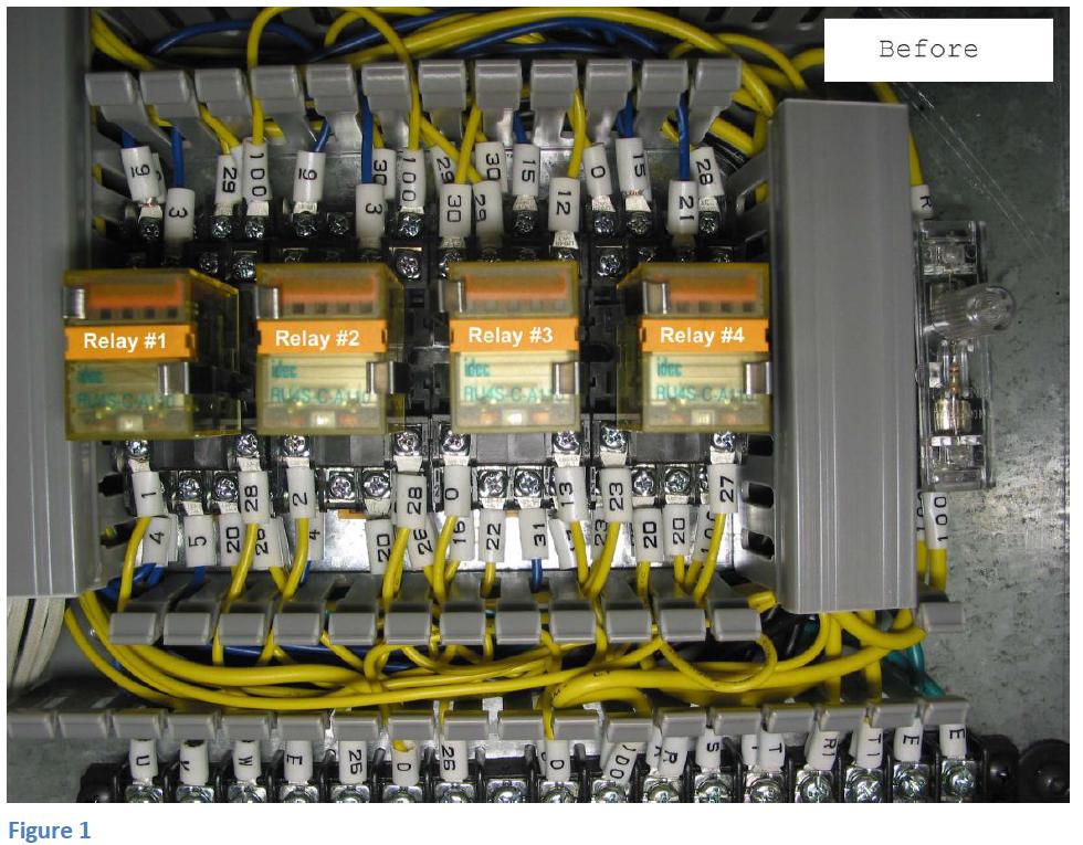
3 Connect wire labeled 32 to terminal labeled AM. Connect wire labeled 33 to terminal labeled AC. Connect wire labeled 8 to terminal labeled V+. Step 14 Wires labeled 5, 21, and 31 are NOT used and should be removed. Trace out each wire and disconnect the ends from their respective terminals. Note: Wire 5 is connected to the bottom terminal located beneath Relay #1, 2 nd terminal from left. Wire 21 is connected to the bottom terminal located above Relay #4, 3 rd terminal from left. Wire 31 is connected to the bottom terminal located beneath Relay #3, 3 rd terminal from left. Step 15 Step 16 Step 17 Step 18 Step 19 Remove both wires labeled 21 from the top of Relay #4 (bottom row, 3 rd terminal from left). If it has not already been done from the previous step, trace out both wires and disconnect them from their respective terminals. Locate the two wires labeled 15 located above Relay #4 (top row, 2 nd terminal from left), now add/connect the supplied jumper wire labeled 15 to the same terminal and secure the other end of the yellow jumper wire labeled 15 to the terminal where wire 21 was removed from (bottom row, 3 rd terminal from left). Refer to Figure 2 for visual details. Remove the yellow jumper wire labeled 20 beneath Relay #4 (bottom row, 2 nd terminal from left) but DO NOT remove the 2 nd wire labeled 20; tighten screw to secure this wire. Connect one end of the yellow wire labeled S6 to the terminal located beneath relay #4 (bottom row, 3 rd terminal from left). Route and connect the other end of the wire to the terminal labeled S6 on the Yaskawa V1000 drive. Refer to Figure 2 for visual. Installation of the Yaskawa V1000 drive is now complete. The drive has already been programmed and ready for operation. Prior to powering on the machine for testing, verify that all connections are properly secured and terminated. After testing, power off machine and replace all covers that have been removed.
4

5
Single cable kit for the FCB1010
 Single cable kit for the FCB1010 1. What is it? With this kit, you can turn your FCB1010 into a phantom powered floorboard, which can do 2-way MIDI communication over one single cable. After installing
over time. Improper wiring practices could result in drive malfunction due to loose terminal connections. Control Circuit Terminal Block Functions Dri
 Figure 3.14 Main speed frequency reference. Multi-function programmable Safety input Forward run/stop Reverse run/stop External fault Fault reset Multi-step speed 1 main/aux switch Multi-step speed 2 Jog
E1135C PDU and Pod Upgrade Procedure
 E4030-90010 Rev. B 12/2003 In this Document... Tools Needed, 2 Contents of the Upgrade Kits, 2 Installation Procedures, 4 Verifying the Power Option of the New PDU, 4 Removing the PDU from the Support
Installing a Power over Ethernet injector
 Installing a Power over Ethernet injector AlphaEclipse StreetSmart and RoadStar signs The instructions in this document explain how to install/replace a Power over Ethernet (PoE) injector in a StreetSmart
LARGE S URGE-PROTECTOR S HELTER
 LARGE S URGE-PROTECTOR S HELTER The weather-resistant Large Surge-Protector Shelter (simply referred to as the shelter in this manual) provides protection from the elements for Surge Protectors (not included)
Instruction Manual (Supplementary) Totally-Enclosed Box Type Inverter
 Totally-Enclosed Box Type Inverter") 2 Instruction Manual (Supplementary) Totally-Enclosed Box Type Inverter TOSVERT VF-S11 Thank you for purchasing a Toshiba Totally-enclosed box type TOSVERT VF-S11 series inverter. This Manual gives a supplementary
2 Instruction Manual (Supplementary) Totally-Enclosed Box Type Inverter TOSVERT VF-S11 Thank you for purchasing a Toshiba Totally-enclosed box type TOSVERT VF-S11 series inverter. This Manual gives a supplementary
A Axis M-Functions Level 1 A Axis Standard A Axis SMT Level 2. Each console includes the following:
 Hardware List The 3000M Crusader II Upgrade system has been custom configured to provide the necessary hardware required for installation on your machine. Verify that you have received all the correct
GV3000/SE AC Drive ControlNet Network Communication Option Board M/N 2CN3000
 GV3000/SE AC Drive ControlNet Network Communication Option Board M/N 2CN3000 Instruction Manual D2-3390-2 The information in this manual is subject to change without notice. Throughout this manual, the
RSL PSM-2 Power Supply Module Project: Modifying a FlatCap2
 RSL PSM-2 Power Supply Module Project: Modifying a FlatCap2 Dear Do-It-Yourselfer, The stock FlatCap2 is less than a stellar performer. Used with a CD5 CD player, for example, it gives flabby bass control,
COMPLETE S YSTEM SHELTER
 COMPLETE S YSTEM SHELTER The weather-resistant Complete System Shelter (CSS) provides protection from the elements for system components such as the console, Solar Power Kit components, sensor interface
SERVICE INSTRUCTIONS CONVERT OLD SFC TO NEW SFC WARNING WARNING WARNING
 SERVICE INSTRUCTIONS CONVERT OLD SFC TO NEW SFC Technical Service Upgrade Instructions Please read complete instructions prior to starting. WARNING This upgrade kit shall be installed by a qualified service
IMPORTANT AS YOU REMOVE THE CONNECTORS LABEL THE CONNECTOR WITH THE NAME OF PLUG WITH THE SHARPIE
 TOOLS REQUIRED : small flat head screwdriver no wider than ⅛ or 3mm wide, phillips head screwdriver, 3mm allen wrench, self tapping screws #6 x ½, ¼ hex head driver, electric drill, wire cutters, fine
Control Box Setup - PRSalpha
 888-680-4466 ShopBotTools.com Control Box Setup - PRSalpha Copyright 2016 ShopBot Tools, Inc. page 1 Copyright 2016 ShopBot Tools, Inc. page 2 Parts List: Hooking Up a PRSalpha Gantry Tool Powering the
PoE/FPR Kit for Auto-Sync Time Clock. The Auto-Sync Time Clock is a validated time system with a Web interface and auto discovery.
 ASTCPOEK PoE/FPR Kit for Auto-Sync Time Clock The Auto-Sync Time Clock is a validated time system with a Web interface and auto discovery. The ASTCPOEK Kit provides Power over Ethernet with Full Power
AB-2D AB-2D SPEAKER A,B OR A+B SELECTOR INSTALLATION & OPERATION GUIDE
 M O D E L AB-2D AB-2D SPEAKER A,B OR A+B SELECTOR INSTALLATION & OPERATION GUIDE AB-2D Speaker/Amplifier Selector TABLE OF CONTENTS Introduction 1 Features and Benefits 1 Installation Considerations 3
TECHKNOW, INC. Kiosk Order Confirmation System INSTALLATION MANUAL. Revision Date: July 11, 2012 Part # Version 3.2
 document Page 1 of 18 TECHKNOW, INC Kiosk Order Confirmation System INSTALLATION MANUAL Revision Date: July 11, 2012 Part # Version 3.2 Techknow, Inc. 393 Mayfield Road Duncan, SC 29334 www.gotechknow.com
CONSOLE CONNECTOR KIT 9501 INSTALLATION INSTRUCTIONS
 CONSOLE CONNECTOR KIT 9501 INSTALLATION INSTRUCTIONS FOR USE WITH: HAMMOND Organ Models L-100, M-100 Series, M-l, M-2, M-3 LESLIE Speaker Models 760, 770, 825 KIT CONTENT Console Connector Assembly 043075
Standard Strip Series
 Standard Strip Series Standard Strip STS-12 LED Lighting Systems Installation Manual (Version 1.3) YESCO LLC, 5119 South Cameron Street, Las Vegas, NV 89118 Table of Contents Introduction 1 Mounting Diagrams
ARABLE BRIDGE QUICK START GUIDE
 ARABLE BRIDGE QUICK START GUIDE Table of Contents 1 2 3 4 5 6 7 8 9 10 11 12 13 14 15 16 Background Compatible Sensors Mounting the Arable Bridge Connect the Solar Panel Connect the Mark Connecting the
Pico Amiga ATX power adaptor install guide
 Pico Amiga ATX power adaptor install guide Introduction The ATX power adaptor allows you to power your Amiga A500/A600/A1200 or CD32 from a modern ATX power supply. This variant of the design has a right
ARES 2 Tone Sequential Tone Decoder Kit Assembly Instructions
 Tools Required: ARES Tone Sequential Tone Decoder Kit Assembly nstructions 3/8 Electric Drill Soldering ron Wire Strippers Needle Nose Pliers Wire Cutters Ruler 60/40 Solder Phillips Screw Driver /8, 5/64,
MACRO MODCHIP FOR XBOX360 CG2 INSTALLATION INSTRUCTIONS
 MACRO MODCHIP FOR XBOX360 CG2 INSTALLATION INSTRUCTIONS List of tools and materials needed: Modchip, flexible LED add-on board, 6 tac switches Microsoft wireless CG2 controller Soldering iron and thin
Chore-Tronics IDM Board Instruction
 Chore-Tronics IDM Board Instruction Caution, Warning and Danger Decals have been placed on the equipment to warn of potentially dangerous situations. Care should be taken to keep this information intact
Schneider Automation Modbus Plus Network Installing Clustered Node Devices Publication: 890 USE Rev. 1.0 Part Number:
 Schneider Automation Modbus Plus Network Installing Clustered Node Devices Publication: 890 USE 53 00 Rev..0 Part Number: 3000939 Modbus Plus devices must be installed as specified in a network layout
GV-EL124S Electric Strike
 GV-EL124S Electric Strike Featured with a built-in door status sensor, the GV-EL124S is a fail-secure electric strike, but it is field convertible from fail secure to fail safe. It can be mounted either
TraceTek Leak Detection Master Module Installation Instructions TOOLS REQUIRED STORAGE
 TTDM-128 TraceTek Leak Detection Master Module Installation Instructions TRACETEK APPROVALS AND CERTIFICATIONS TYPE NM General Signaling Equipment 76LJ GENERAL INFORMATION Please read these instructions
Plasma Panel Replacement Guide DU-42PX12X
 Plasma Panel Replacement Guide DU-42PX12X Panel Replacement: At this point, the panel has been determined to be defective and replacement is necessary. Upon receiving the replacement panel, it must be
Installation Guide. Retrofit Kit for USB Ready Intraoral Systems
 Installation Guide Retrofit Kit for USB Ready Intraoral Systems Table of Contents Wall-Mount Retrofit Kit... 2 Introduction... 2 Connecting the Articulating and Horizontal Arm Cables... 2 Installing the
ATTENTION: OBSERVE PRECAUTIONS FOR HANDLING ESD-SENSITIVE DEVICES
 15 Monitor Removal 1. Turn off and unplug the game. 2. Place something in front of the game to brace the bezel once the strain relief cord is undone, then unlock and open the CPU section. 3. Remove the
Installation manual CF8-W-Disp-AL
 Installation manual CF8-W-Disp-AL CO 2 transmitter with two relays mounted in industrial housing prepared for Modbus communication protocol 4 7 8 8 6 3 2 5 Wall plate 5 Snap-in lid 2 PCB (Factory supplied
ZC-OH5 TAMPER-RESISTANT INDOOR/OUTDOOR HOUSING INSTRUCTION MANUAL FOR USE WITH GANZ ZC-D5000 SERIES MINIDOME CAMERAS
 ZC-OH5 TAMPER-RESISTANT INDOOR/OUTDOOR HOUSING INSTRUCTION MANUAL FOR USE WITH GANZ ZC-D5000 SERIES MINIDOME CAMERAS Please carefully read and observe all instructions and warnings contained in this manual
AC300/AC400 SERIES DYNAMIC BRAKING and ADDITIONAL FORM C RELAY. INSTALLATION INSTRUCTIONS Document Number:
 Minarik Variable Speed AC Motor Drives AC300/AC400 SERIES DYNAMIC BRAKING and ADDITIONAL FORM C RELAY INSTALLATION INSTRUCTIONS Document Number: 250-0297 These instructions apply to models rated: 7.5 25
1. Mount the echo and tremolo control switches under the keyboard shelf, in a position convenient for the organist.
 CONSOLE CONNECTOR KIT 8101 INSTALLATION INSTRUCTIONS FOR USE WITH: HAMMOND Organ Models A-100, D-100, RT2, RT3 LESLIE Speaker Models 122, 122RV KIT CONTENT Console Connector Assembly 047357 Echo Control
Tubbutec SH-1oh1 µtune
 Tubbutec SH-1oh1 µtune Midi retrofit and feature extension for Roland SH-101 Installation Manual http://tubbutec.de 1 Contents Contents 2 1 Installation of the SH-1oh1 mod - µtune edition 3 1.1 Opening
PXC Compact Unitary Equipment Controller (UEC)
") Document No. 553-169 PXC Compact Unitary Equipment Controller (UEC) Product Description The PXC Unitary Equipment Controller (UEC) is an MS/TP device that can be configured as a programmable, stand-alone
Document No. 553-169 PXC Compact Unitary Equipment Controller (UEC) Product Description The PXC Unitary Equipment Controller (UEC) is an MS/TP device that can be configured as a programmable, stand-alone
Galaxy Rectifier Shelf Field Replacement
 Galaxy Rectifier Shelf Field Replacement Model PWRSYS-RFK-A203 Installation Guide Galaxy Rectifier Shelf Field Replacement Model PWRSYS-RFK-A203 Installation Guide, Part Number 139691-1 Copyright 2011,
Replacing the Power Supply
 APPENDIX B This appendix includes information on how to replace the power supply for the Cisco AS550XM universal gateway and contains the following sections: Safety Recommendations, page B-1 Required Tools
TIVO UPGRADE INSTRUCTIONS (c) , Adberg Consulting LLC. All rights reserved.
 , Adberg Consulting LLC. All rights reserved.") TIVO UPGRADE INSTRUCTIONS (c) 2001-2003, Adberg Consulting LLC. All rights reserved. Instructions for Series 1 DirecTV/TiVo GXCEBOT TWO-DRIVE REPLACE upgrade Color instructions are also available at http://www.weaknees.com/upgrade_instructions.php
TIVO UPGRADE INSTRUCTIONS (c) 2001-2003, Adberg Consulting LLC. All rights reserved. Instructions for Series 1 DirecTV/TiVo GXCEBOT TWO-DRIVE REPLACE upgrade Color instructions are also available at http://www.weaknees.com/upgrade_instructions.php
Royal RVV-500 (B) Retrofit Kit
 Retrofit Kit") Optipay BV/RC/CC into a Non-Fascia Vending Machine This document contains information for installing and configuring the JCM Optipay DBV-01 Bill Validator, RC-10 Bill Recycler and A-66 Coin Changer into
Optipay BV/RC/CC into a Non-Fascia Vending Machine This document contains information for installing and configuring the JCM Optipay DBV-01 Bill Validator, RC-10 Bill Recycler and A-66 Coin Changer into
G12/G12x USER S MANUAL
 G12/G12x USER S MANUAL TABLE OF CONTENTS SECTION 1 SLIDE CONFIGURATION SECTION 2 SLIDE CONFIGURATION ACCESSORIES SECTION 3 TABLETOP CONFIGURATION SECTION 4 TABLETOP CONFIGURATION ACCESSORIES SECTION 5
PEREGRINE SERIES RETROFIT INSTALLATION GUIDE
 06.05.17 HanleyLED H100W-PPS524V Spec Sheet SOLUTIONS THAT MAKE SENSE PEREGRINE SERIES RETROFIT INSTALLATION GUIDE Light Up New Markets Your Local Distributor: Grimco US www.grimco.com 800.542.9941 Canada
INSTALLATION INSTRUCTIONS
 2015 F-150 8 MyTouch factory display 360º Vision System (Kit # AVMS-3618) DUE TO THE COMPLEXITY OF THIS KIT PROFESSIONAL INSTALLATION IS REQUIRED CALIBRATION KIT IS REQUIRED FOR FINAL PROGRAMMING -Must
Three Phase Residential Solution for Australia, System Design and Installation Guidelines
 Three Phase Residential Solution for Australia, System Design and Installation Guidelines This document describes how to design and install SolarEdge three phase inverters for residential installations.
CAMERA ASSEMBLY. Removal/Replacement of the Camera Box Assembly APR-CA. Install Camera Assembly. Remove Camera Assembly
 CAMERA ASSEMBLY Removal/Replacement of the Camera Box Assembly APR-CA REQUIRED TOOLS: 9/64 hex key Small flat-tip screwdriver Remove Camera Assembly camera 1. Locate the camera assembly underneath the
EQ573 Assembly guide. EQ573 Assembly guide Main board 1. Diodes. 2. Resistors (1) 3. Test pins. 4. Ceramic capacitors.
 3. Test pins. 4. Ceramic capacitors.") EQ573 Assembly guide Safety warning The kits are main powered and use potentially lethal voltages. Under no circumstance should someone undertake the realisation of a kit unless he has full knowledge about
EQ573 Assembly guide Safety warning The kits are main powered and use potentially lethal voltages. Under no circumstance should someone undertake the realisation of a kit unless he has full knowledge about
AutoMax Network Communication Option Board for use with GV3000/SE AC Drives M/N 2AX3000
 AutoMax Network Communication Option Board for use with GV3000/SE AC Drives M/N 2AX3000 Instruction Manual D2-3308-7 The information in this manual is subject to change without notice. Throughout this
InView Marquee Message Display
 Installation Instructions InView Marquee Message Display Introduction These instructions show how to change the serial address and how to mount InView series signs with NEMA Types 4, 4X, and 12 enclosures.
SmartLogger1000 Quick Guide. Issue: 10 Part Number: Date: HUAWEI TECHNOLOGIES CO., LTD.
 SmartLogger1000 Quick Guide Issue: 10 Part Number: 31505707 Date: 2017-06-13 HUAWEI TECHNOLOGIES CO., LTD. 1. The information in this document is subject to change without notice. Every effort has been
PDC / ECIS. Display Update update with conversion kit Display Update. Contents. General information. Important notes.
 US Toll Free: 800.BODE.TEC BodeTechnicalServices.com Display Update PDC / ECIS Display Update update with conversion kit 535268 Contents General information Important notes Requirements Conversion instructions
M40e and M160 CIP Installation Instructions
 Part No. 530-005365-01 Revision 2 23 January 2002 CIP Description This document describes how to remove and replace the Connector Interface Panel (CIP) on a Juniper Networks M40e Internet router or M160
Installation Instructions. Ecast Mojo B75B Motherboard Upgrade Kit Kit #
 Installation Instructions Ecast Mojo B75B Motherboard Upgrade Kit Kit #26684501 This kit contains the parts and instruction to install the B75B Motherboard into your Ecast Mojo jukebox. Tools Required
Treadmill Embedded Touch Screen Won t Power Up
 Treadmill Embedded Touch Screen Won t Power Up E-TRe and E-TRxe This document contains the necessary information to troubleshoot a treadmill with an embedded touch screen that will not power up. Follow
Canon EOS Rebel T2i Top Cover Replacement
 Canon EOS Rebel T2i Top Cover Replacement Replacing the top piece of a Canon T2i (550D). In my case, I had a broken hot-shoe, but as most controls on this camera are built into the same part, this repair
View Wall Interface. Dynamic Glass INSTALLATION GUIDE. Description. System Requirements. Installation Overview
 Description The solution is a compact, wall-mounted interface used for monitoring and changing the tint levels of View Dynamic Glass. The product leverages 802.11-based Wi-Fi technology for connectivity
Warning Before Installation. Package Contents EN - 1. Refer to your user s manual for the operating temperature.
 5000020G Warning Before Installation English Power off the Network Camera as soon as smoke or unusual odors are detected. Do not place the Network Camera on unsteady surfaces. Do not insert sharp or tiny
ADDENDUM FOR 20, 27, & 28 OPTIONS
 ADDENDUM FOR 20, OPTIONS GENERAL The 20, 27, and 28 option provides for an alarm contact OR an AC transfer switch on EXELTECH XP Series inverters. The alarm relay monitors the inverter s AC output and
BuffaloLabs WiFi Lantern Assembly guide version 1
 BuffaloLabs WiFi Lantern Assembly guide version 1 Needed equipment: Solder iron Solder wire Cutter Wire stripper (optional) Hot glue gun Overview of the components (not including USB cable and box panels)
Installing Keypad and Backplate
 Installing Keypad and Backplate Fig.1 Positioning of Fixing Holes and Cable Outlet Cable Outlet, Drill Diameter 10mm for Cable Access Remove the back plate, which is fitted to rear of the keypad, using
Upgrade Instructions. P/N Revision A. October Printer Terminal Holder * *
 Upgrade Instructions P/N 96-08-0 Revision A October 000 480 Printer Terminal Holder P/N 96-08-0 Revision A *96080* Instructions This terminal holder connects the INTERMEC R 600 Series and 700 Series Computers
Instruction Manual. Electrical Management System (EMS) EMS-HW30C & EMS-HW50C
 EMS-HW30C & EMS-HW50C") Instruction Manual Electrical Management System (EMS) EMS-HW30C & EMS-HW50C EMS-HW50C EMS-HW30C! CAUTION These instructions are intended to provide assistance with the installation of this product, and
Instruction Manual Electrical Management System (EMS) EMS-HW30C & EMS-HW50C EMS-HW50C EMS-HW30C! CAUTION These instructions are intended to provide assistance with the installation of this product, and
Installing 6 Indexer: PRS Standard Tools
 888-680-4466 ShopBotTools.com Installing 6 Indexer: PRS Standard Tools Copyright 2016 ShopBot Tools, Inc. page 1 Copyright 2016 ShopBot Tools, Inc. page 2 Table of Contents Overview...5 Installing the
LANCER / LANCER EVOLUTION (2008 ) REAR VIEW CAMERA MZ380462EX INSTALLATION AND HANDLING INSTRUCTIONS
 REAR VIEW CAMERA MZ380462EX INSTALLATION AND HANDLING INSTRUCTIONS") LANCER / LANCER EVOLUTION (2008 ) REAR VIEW CAMERA MZ380462EX INSTALLATION AND HANDLING INSTRUCTIONS Navigation (MMCS) unit Camera Thank you for purchasing the Mitsubishi Genuine Accessory. To install
LANCER / LANCER EVOLUTION (2008 ) REAR VIEW CAMERA MZ380462EX INSTALLATION AND HANDLING INSTRUCTIONS Navigation (MMCS) unit Camera Thank you for purchasing the Mitsubishi Genuine Accessory. To install
Golf Control Panel Conversion Instructions
 Golf Control Panel Conversion Instructions Document Part #: 040-0079-01 This document describes the steps for upgrading the control panel on an old golf cabinet for use with an EA SPRTS PGA TUR Golf Conversion
Emax SE SCSI Port Emax Plus Retrofit Instructions (Fl360)
") Emax SE SCSI Port Emax Plus Retrofit Instructions (Fl360) Tools needed: Exacto Knife, Vacuum Desoldering Tool, Soldering Iron, Solder, Phillips Screwdriver, Needle Nose Pliers, 1/2 Nut Driver, 5/8 and
Emax SE SCSI Port Emax Plus Retrofit Instructions (Fl360) Tools needed: Exacto Knife, Vacuum Desoldering Tool, Soldering Iron, Solder, Phillips Screwdriver, Needle Nose Pliers, 1/2 Nut Driver, 5/8 and
How to hardwire the Olympus D-370 and D-380 Digital Cameras
 How to hardwire the Olympus D-370 and D-380 Digital Cameras Copyright, PixController http://www.pixcontroller.com, all rights reserved. This document covers in detail how to modify either the Olympus D-370
Coin Acceptors, Inc. Installation Instructions for the 4.3 Touch Screen Display
 Coin Acceptors, Inc. Installation Instructions for the 4.3 Touch Screen Display Kit # 410930 and 410930-1 DN3800 and DN5800 Publication 928412 1 Hand Drill Utility Knife Step Ladder 5/8 Drill Bit Tools
To connect the AC adapter:
 Replacing the AC Adapter Replacing the AC Adapter 3 Plug the power cord into a wall outlet. The power indicator turns on. To connect the AC adapter: Connect the power cord to the AC adapter. Power indicator
ILC LightLEEDer MicroLite 1000P Retrofit Installation
 ILC LightLEEDer MicroLite 1000P Retrofit Installation Congratulations on the purchase of your new ILC LightLEEDer Retrofit System. The ILC LightLEEDer MicroLite Retrofit System is designed for the replacement
PRODUCT MANUAL Duet DMX & Wireless RGB-W Controller
 Product Description Solid Apollo LED s new wall mounted Duet DMX & RGB-W LED Controller has been created to control LED light fixtures in three different ways. Users can independently control DMX enabled
INSTALLATION INSTRUCTIONS
 CONSOLE CONNECTOR KIT 7830 FOR USE WITH: LESLIE Speaker Model 130 Various single and double channel organs INSTALLATION INSTRUCTIONS KIT CONTENT Console Connector 137283 Switch Assembly, Cable Assembly,
Ag Leader Technology. DirectCommand Installation Hardi 20-pin Interface Kit (Sprayer Chassis Mount)
") Part Name / Description Part Number Quantity DirectCommand Hardi Sprayer Kit 4100882 1 Dust Receptacle 8-pin 2002975-8C 1 Installation Instructions 2006335 1 Quick Reference Card- Liquid Application 2002831-38
Part Name / Description Part Number Quantity DirectCommand Hardi Sprayer Kit 4100882 1 Dust Receptacle 8-pin 2002975-8C 1 Installation Instructions 2006335 1 Quick Reference Card- Liquid Application 2002831-38
User Manual. PCKeypad Wireless Keypad
 User Manual PCKeypad Wireless Keypad Description The PCKeypad is a wireless keypad with a PentaCODE transmitter built-in. It works with all of Elsema s PCR series receivers. The installer has the option
Home Automation, Inc. Model 53A00-1. OmniTouch 5.7 Touchscreen with Video
 Home Automation, Inc. Model 53A00-1 OmniTouch 5.7 Touchscreen with Video Installation Manual Document Number 53I00-1 Rev A June, 2007 FCC NOTICE This device complies with FCC Rules Part 15. Operation is
Motorized Ceiling TV Mount
 Motorized Ceiling TV Mount Instruction Manual SKU: MOUNT-E-FD55 Scan the QR code with your mobile device or follow the link for helpful videos and specifications related to this product. https://vivo-us.com/products/mount-e-fd55
How to build an Olympus D-360L Trail Camera using the PixController Universal "Digital Trail Camera Kit" w/ RS-232-U PIC Chip
 Copyright, PixController, Inc. http://www.pixcontroller.com, all rights reserved. How to build an Olympus D-360L Trail Camera using the PixController Universal "Digital Trail Camera Kit" w/ RS-232-U PIC
Star Trac Fitness E-ST 5090 Stepper. Install Guide
 Star Trac Fitness E-ST 5090 Stepper Install Guide STAR TRAC E-ST STEPPER Install Guide E-ST 5090 E Series Stepper ASSEMBLY AND SETUP The following parts are included with the base STAR TRAC E-ST STEPPER:
BehringerMods.com. Instructions for modification of Behringer SRC analog inputs and outputs
 BehringerMods.com Instructions for modification of Behringer SRC analog inputs and outputs The following instructions will cover the details of fully modifying a unit with analog output and analog input
Warning Before Installation. Package Contents EN - 1. Refer to your user's manual for the operating temperature.
 510000221G Warning Before Installation English Power off the Network Camera as soon as smoke or unusual odors are detected. Do not place the Network Camera on unsteady surfaces. Do not insert sharp or
Upgrade Instructions Printer Terminal Holder
 Upgrade Instructions 6820 Printer Terminal Holder Instructions Terminal Holder Installation Kit The terminal holder connects INTERMEC R computers to the 6820 Printer. Do these instructions, in the order
H Manual Stretch Wrap Machine uline.com FILM ROLL CAPACITY TECHNICAL DATA ELECTRICAL SPECIFICATIONS TURNTABLE SPECIFICATIONS
 H-2304 Manual Stretch Wrap Machine 1-800-295-5510 uline.com SYSTEM SpecificationS IMPORTANT! Read this manual thoroughly and familiarize yourself with ALL controls and operating features. Keep this manual
Toshiba Satellite A105-S4011 Touchpad
 Toshiba Satellite A105-S4011 Touchpad Replacement This guide will instruct you on how to remove the current touchpad from this laptop and how to reinstall another. This is a straightforward process and
Removal and Installation8
 8 Screw Types 8-4 Top Cover Assembly 8-5 Left Hand Cover 8-6 Right Hand Cover 8-10 Front Panel Assembly 8-14 Left Rear Cover 8-15 Right Rear Cover 8-16 Extension Cover (60" Model only) 8-17 Media Lever
XDBKITS5 Bus / DB Terminal Kit (Size 5) Installation Manual DPD00116
 Installation Manual DPD00116") XDBKITS5 Bus / DB Terminal Kit (Size 5) Installation Manual DPD00116 XDBKITS5 Option Kit Installation Manual vacon 3 Installing the Bus / DB Terminal Option Kit Introduction The XDBKITS5 option kit is
XDBKITS5 Bus / DB Terminal Kit (Size 5) Installation Manual DPD00116 XDBKITS5 Option Kit Installation Manual vacon 3 Installing the Bus / DB Terminal Option Kit Introduction The XDBKITS5 option kit is
Nov. 07, 2013 p. 5 - changed the B axis unit value to from Changed by Randy per Frank s request.
 Correction notes Nov. 07, 2013 p. 5 - changed the B axis unit value to 45.1389 from 40.0000. Changed by Randy per Frank s request. Jan. 22, 2018 p. 5 - changed the B axis unit value and corresponding picture
HARDWARE ASSEMBLY MANUAL
 HARDWARE ASSEMBLY MANUAL P336: System Dynamics Filtering Laboratory Release Date: February 7, 203 P336 Revision: B PURPOSE The purpose of this document is to outline the procedures to be used in order
RMB Peripheral Units Installation Guide
 RMB Peripheral Units Installation Guide Part Number 65-000101 2011 by Kentrox, Inc. All rights reserved. Copyright 2011 by Kentrox, Inc. All Rights Reserved. The material discussed in this publication
MacBook Core 2 Duo Clutch Cover
 MacBook Core 2 Duo Clutch Cover Replacement Replace the clutch cover on your MacBook Core 2 Duo. Written By: Ben Eisenman ifixit CC BY-NC-SA www.ifixit.com Page 1 of 29 INTRODUCTION Replace the curved
Pan-Tilt-Zoom Security Camera
 Security Made Smarter Pan-Tilt-Zoom Security Camera For use with Swann Pro-Series 080p DVRs EN INSTRUCTION MANUAL M080VERE Swann 07 7 5 8 6 4 VIDEO INPUT 4 INPUT OUTPUT VGA RS485 LAN V Step One - Introduction
Toshiba Satellite A210 Motherboard
 Toshiba Satellite A210 Motherboard Replacement In this guide you will learn how to properly remove the Motherboard. Written By: Devin ifixit CC BY-NC-SA www.ifixit.com Page 1 of 12 INTRODUCTION Before
This page outlines some of the alternate pieces that can be used for building.
 Artbotics Exploring Mechanisms with Lego Mindstorms EV3 This packet contains information on each mechanism you will be using, including a to-scale image of all of the pieces needed to build each one and
A Backlighted LCD for your K1
 A Backlighted LCD for your K1 (K1BKLTKIT) Tom Hammond - NØSS, July 27, 2006 Rev C Thanks to Wayne Burdick, N6KR for suggesting this implementation of backlighting the K1 display. APPLICABILITY This modification
Adapter Kit for PanelView 1200/1200e Touch Screen Terminal Cutout
 Installation Instructions Adapter Kit for PanelView 1200/1200e Touch Screen Terminal Cutout Catalog Numbers 2711-NR5T, 2711P-RAT12E2 Topic Page About This Publication 1 Important User Information 2 About
Installation instructions DC Protection and Delay unit, Version 1.2 The package should contain: A piece of normal gauge yellow wire for the AC connect
 Installation instructions DC Protection and Delay unit, Version 1.2 How does the unit work? Delay: Basically a capacitor is charged via a resistor, when the voltage of the capacitor reach a certain level,
Power connections 3) Power from 2024 to Control box (The valve harness connected) Ground (0V) +24 V. The voltage between pins 1 & 2 in JPT# 123
 Power from 2024 to Control box (The valve harness connected) Ground (0V) +24 V. The voltage between pins 1 & 2 in JPT# 123") Power connections 3) Power from 2024 to Control box (The valve harness connected) The voltage between pins 1 & 2 in JPT# 123 connector should be +24V. 4) Power from 2024 to Control box The voltage between
Power connections 3) Power from 2024 to Control box (The valve harness connected) The voltage between pins 1 & 2 in JPT# 123 connector should be +24V. 4) Power from 2024 to Control box The voltage between
Honeywell VFD CORE User and Application Manual
 Honeywell VFD CORE User and Application Manual INSTALLATION INSTRUCTIONS CONTENTS Chapter 1: Introduction... 2 Chapter 2: Installation... 11 Chapter 3: Unpacking... 15 Chapter 4: Wiring... 19 Chapter 5:
A-100G6 - Basic frame assembly diagram
 doepfer System A - 100 Rack system A-100 G A-100G6 - Basic frame assembly diagram Parts: 1 Rail with lip, and with tapped hole strip inserted (with M3 threads). 2 Rail with lip, with three M3 hexagon nuts
Shop Fox Fence Kit Installation Instructions:
 Shop Fox Fence Kit Installation Instructions: Please note this installation kit is designed solely for installation on a Shop Fox Classic Fence. Accurate Technology manufactures kits for other saw fences
Megatouch FORCE Monitor Chassis Board Replacement
 Megatouch FORCE Monitor Chassis Board Replacement Visit the Merit Industries, Inc. Web site http://www.meritind.com merit industries, inc. PM0337-01 Rev C Table of Contents FORCE Classic Monitor Chassis
SURFACE CONTROLTrack INSTALLATION INSTRUCTIONS
 SURFACE CONTROLTrack INSTALLATION INSTRUCTIONS IMPORTANT SAFETY INSTRUCTIONS - For use with CONTROLTrack System Only When installing or using this track system, basic safety precautions should always be
CONTROLLER BOARD CONVERSION KIT Rev Installation Instructions Part Number: PUPKIT
 CONTROLLER BOARD CONVERSION KIT Rev. 2009 Installation Instructions Part Number: PUPKIT The PUPKIT controller is designed to replace existing full height turnstile installations employing the Robot Industries