ISOBUS Quick Reference Installation Guide. Liquid Fertilizer Anhydrous Ammonia Sprayer Spreader Slurry
|
|
|
- Tabitha Leonard
- 6 years ago
- Views:
Transcription


1 ISOBUS Quick Reference Installation Guide Liquid Fertilizer Anhydrous Ammonia Sprayer Spreader Slurry 1
2 2
3 Table of Contents 1 ISOBUS System Overview Anhydrous Ammonia / Liquid Fertilizer Sprayer Spreader Slurry Liquid Fertilizer / NH3 / Sprayer Installation Cabling Diagram Field-IQ/AccuGuide/IntelliRate Cabling Field-IQ/AccuGuide/IntelliRate Cabling Description Raven 4X0 Series Cabling Raven 4X0 Series Cabling Description Raven 4XX0 Series Cabling Raven 4XX0 Series Cabling Description Physical Installation Spartan Direct Injection System Spreader Installation Cabling Diagram Field-IQ/AccuGuide/IntelliRate Cabling Field-IQ/AccuGuide/IntelliRate Cabling Description Raven 660 Series Cabling Raven 660 Series Cabling Description Physical Installation Slurry Installation Slurry Cabling Diagram Slurry Cabling Diagram Description Physical Installation ISOBUS Resources ISOBUS Demo Stand ISOBUS Online Resources
4 4


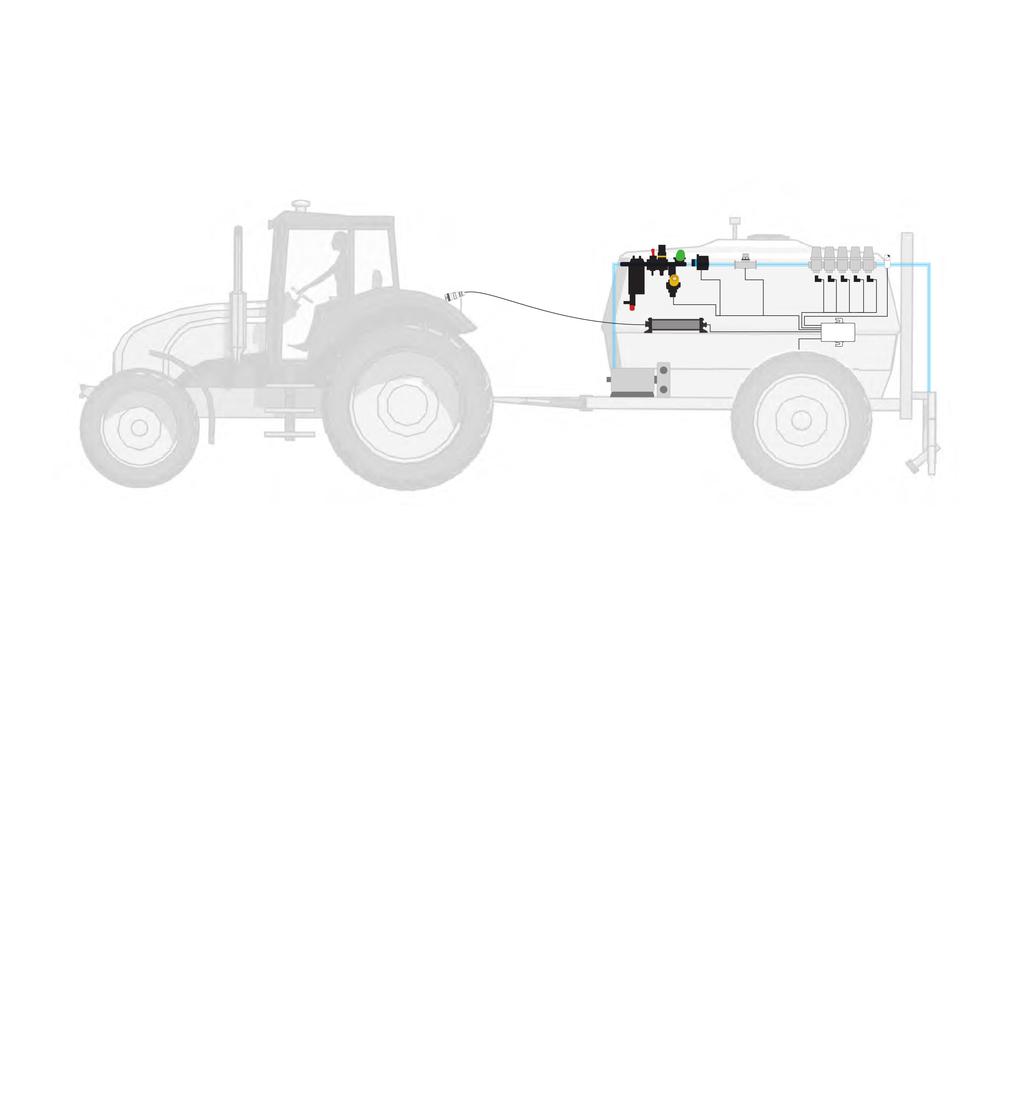
5 1 ISOBUS System Overview 1.1 Anhydrous Ammonia/Liquid Fertilizer ISOBUS compatible display ISOBUS ready tractor v q w ISOBUS Harness ISOBUS ECU e r ISOBUS Liquid ECU Harness Component cabling 1.2 Sprayer ISOBUS compatible display ISOBUS ready tractor v q w ISOBUS Harness ISOBUS ECU e r ISOBUS Liquid ECU Harness Component cabling 5


6 1.3 Spreader ISOBUS compatible display ISOBUS ready tractor hopper cover bin level bin level belt speed 12v 3 belt speed HYD spinner speed q w ISOBUS Harness e ISOBUS ECU ISOBUS Liquid ECU Harness 1.4 Slurry ISOBUS compatible display ISOBUS ready tractor v q w ISOBUS Harness e ISOBUS ECU r ISOBUS Liquid ECU Harness Component cabling 6
7 2 Liquid Fertilizer/NH3/Sprayer Installation 2.1 Cabling Diagram 7
8 2.2 Field-IQ/AccuControl/IntelliRate Cabling 8
9 2.3 Field-IQ/AccuControl/IntelliRate Cabling Description Item Description Part Number Part Number Description 1 ISOBUS Harness ME ME ME ME ME ME ME Liquid Fertilizer ECU ME Implement with Master Switch - 3ft. Implement with Master Switch - 8ft. Implement with Master Switch - 13ft. Implement with Master Switch - 21ft. Implement with Master Switch - 28ft. Implement with Master Switch - 36ft. Implement with Master Switch - 43ft. 3 Liquid Fertilizer ECU Complete Harness ME Master/Implement Switch 5 Radar input connection 6 Tank control connection 7 Power connection 8 Section connection 9 Rate connection 10 Aux. connection 11 Section Valve Adapter Cable ZTN80587 ZTN80961 ZTN77541 ZTN Field-IQ/AccuCtrl/IntelliRate Adapter Harness ME Field-IQ 5 boom adapter Field-IQ 10 boom adapter Raven 7 boom adapter Raven 10 boom adapter 13 Aux. I/O 14 Spinner control (not applicable for liquid fertilizer) 15 Regulation connection ZTN80534 ZTN80586 ZTN80531 ZTN80960 ZTN81970 ZTN Flow connection Field-IQ to Raven Fast Valve Field-IQ to Raven control valve adapter Field-IQ to Dickey-john control valve Dickey-John PWM control valve adapter Raven Standard valve (round 4-pin lock ring connector) Raven Fast valve (flat 2-pin connector) 17 Flow Meter Cable 18 Flow Control Adapter Cable ZTN80584 ZTN Field-IQ to Raven flowmeter adapter Field-IQ to Dickey-john encoder/flowmeter 9
10 2.4 Raven 4X0 Series Cabling 10
11 2.5 Raven 4X0 Series Cabling Description Item Description Part Number Part Number Description 1 ISOBUS Harness ME ME ME ME ME ME ME Liquid ECU ME Liquid ECU to 4X0 Harness ME Master/Implement Switch 5 Pressure connection 6 Pressure Sensor * Denotes Raven part # * 7 Raven Flow Cable * * Denotes Raven part # * 8 Control Valve 9 Master On/Off Valve 10 Boom Valves 11 Flox Extension Cable * * * * Denotes Raven part # * 12 Flow Meter Implement with Master Switch - 3ft. Implement with Master Switch - 8ft. Implement with Master Switch - 13ft. Implement with Master Switch - 21ft. Implement with Master Switch - 28ft. Implement with Master Switch - 36ft. Implement with Master Switch - 43ft. Flow Cable 6 ft. 3 Boom Flow Cable 12 ft. 3 Boom Flow Extension Cable 6 ft. Flow Extension Cable 12 ft. Flow Extension Cable 24 ft. Flow Extension Cable 36.5 ft. 11
12 2.6 Raven 4XX0 Series Cabling 12
13 2.7 Raven 4XX0 Series Cabling Description Item Description Part Number Part Number Description 1 ISOBUS Harness ME ME ME ME ME ME ME Liquid ECU ME Liquid ECU to 4XX0 Harness ME Master/Implement Switch 5 Raven Flow Cable * * * * Denotes Raven part # * 6 Control Valve 7 Boom Valves * * * Denotes Raven part # * 8 Pressure Sensor Cable * * * * Denotes Raven part # * 9 Optional Pressure Sensor * Denotes Raven part # * 10 Flow Extension Cable * * * * Denotes Raven part # * 11 Flow Meter Implement with Master Switch - 3 ft. Implement with Master Switch - 8 ft. Implement with Master Switch - 13 ft. Implement with Master Switch - 21 ft. Implement with Master Switch - 28 ft. Implement with Master Switch - 36 ft. Implement with Master Switch - 43 ft. Flow Cable 12 ft. 10 Boom Flow Cable 24 ft. 10 Boom Flow Cable 12 ft. 5 Boom Flow Cable 24 ft. 5 Boom Boom Valve Cable - 1 section Boom Valve Cable - 3 section Boom Valve Cable - 5 section Pressure Sensor Cable - 6 ft. Pressure Sensor Cable - 12 ft. Pressure Sensor Cable - 37 ft. Pressure Sensor Cable - 44 ft. Flow Extension Cable - 6 ft. Flow Extension Cable - 12 ft. Flow Extension Cable - 24 ft. Flow Extension Cable ft. 12 Flow Control Adapter Cable ZTN80584 Field-IQ to Raven flowmeter adapter 13

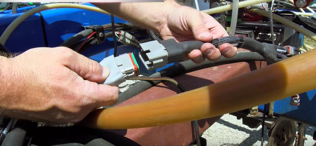
14 2.8 Physical Installation 1. Route the ISO Implement Cable from the ECU to the implement hitch point. This cable will mate with the Tractor ISOBUS connector. (factory equipped) 2. Locate a stable and flat area of the implement approximately 8 by 16 inches. Using four 1/4 x 3/4 length (or another length required) bolts and nylon locking nuts, bolt the ECU to the toolbar. 14


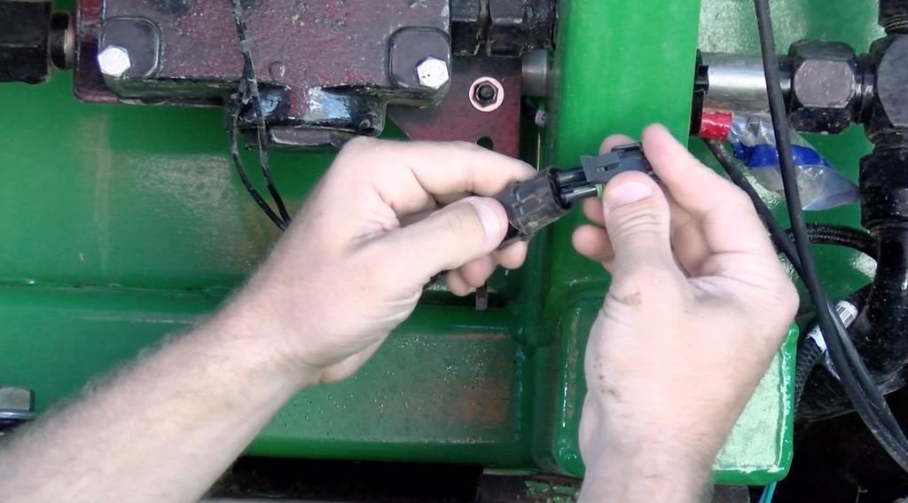
15 3. Plugin the ISO Implement Cable harness to the ISOBUS connection on the ECU. If the harness is connected incorrectly, the system will not power up. 4. Connect the Liquid ECU harness to the 42-pin connector on the ECU. 15
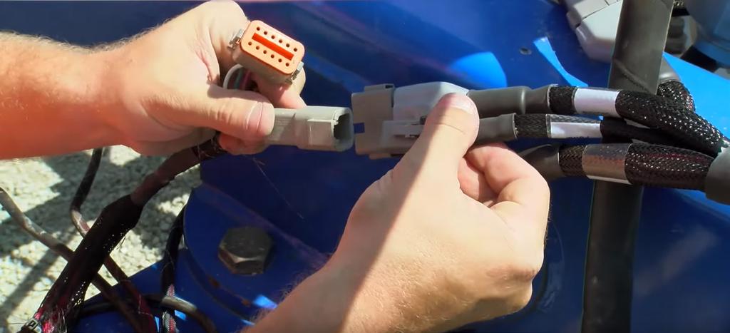
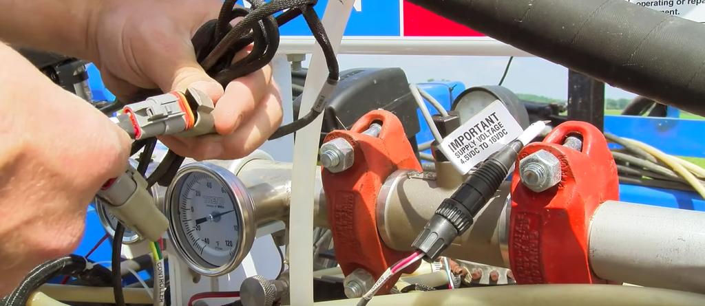
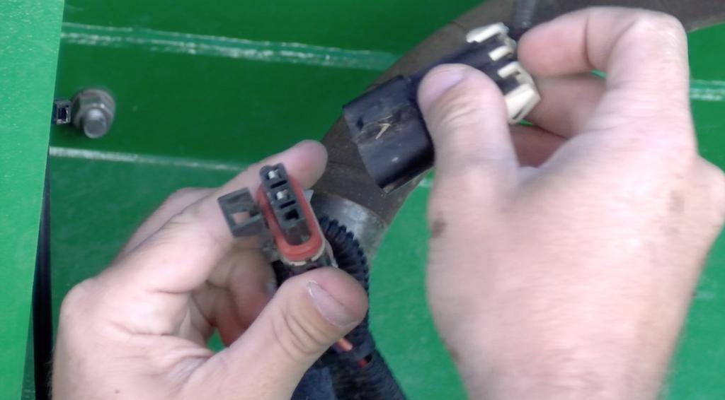
16 16 5. Connect the adapter harness (Field-IQ/AccuControl/IntelliRate, Raven 4X0, Raven 4XX0) to the Liquid ECU harness. Next, connect your adapter harness to the existing components on your implement.

 508-04-140100 Spartan Injection Pump Kit Model 140 (10-80 oz/min) All four pump models are identical as viewed from the outside.")

17 2.9 Spartan Direct Injection System Mueller Electronics recommends the Spartan Direct Injection System for NH3. The parts below are designed and tested to work with the Mueller NH3 system and should be ordered directly from SureFire Ag Systems. Part Number: Description: Spartan Injection Pump Kit Model 110 (2-10 oz/min) Spartan Injection Pump Kit Model 120 (3-20 oz/min) Spartan Injection Pump Kit Model 130 (5-40 oz/min) Spartan Injection Pump Kit Model 140 (10-80 oz/min) All four pump models are identical as viewed from the outside. Each pump model has a different displacement to achieve the desired flow range. The flow switch on the 110 and 120 models is a special low flow switch (which also appears identical from the outside). Specifications for all pump models: Pressure: Max Operating 80 PSI - Care should be taken not to restrict pump outlet as it will develop up to 290 psi which may cause failure of plumbing fittings. Voltage: 12 VDC vehicle electrical system Current: Max 16.3 amps Pump speed: rpm Pump Case Oil: Mobil Super 5W30 Conventional Motor Oil Pump Kit Components: Spartan Injection Pump - 3/8 QC Inlet - 3/8 QC Outlet or ¼ QC Outlet 20 Fused Power Cable w/ 480MP Connector 6 AWG Magnetic Mount Liquid Filled Pressure Gauge w/ Tee Connection 10 PSI Pressure Maintaining Check Valve on Pump Outlet 50 mesh strainer recommended for all installations - Strainer IS NOT included with pump kit - Strainer IS included on 20, 55 & 110 Gallon Spartan Tanks 17

18 Each Spartan pump includes a bag with the items shown to be installed according to this diagram. Mixing chamber and one way check valve sold separately Tank Kits: Part Number: Description: Gallon Spartan Tank Kit Gallon Spartan Tank Kit Gallon Spartan Tank Kit All tank kits include: Mounting location for Spartan pump on the tank bracket 3/8 Hose for connection to pump Strainer The 55 and 100 Gallon Tank kits also include a black tank base for holding rinse water or antifreeze. This makes it extremely easy to flush the Spartan pump daily after use to reduce issues caused by chemical sitting in the pump. 18

19 Mixing Chambers: Part Number: Description: N-Serve Check Valve Part Number TBD NEW Mixing Chamber with built in injection port The 55 and 100 Gallon Tank kits also include a black tank base for holding rinse water or antifreeze. This makes it extremely easy to flush the Spartan pump daily after use to reduce issues caused by chemical sitting in the pump. Recommendations for N-Serve: Spartan is a great pump for injecting N-Serve NH3 Stabilizer. Given customer s implement width, rates and speed SureFire will help choose the right pump model to fit their needs. For many N-Serve cases, the Spartan 130 at 5-40 oz/min is the best fit. Width Speed Rate Spartan Flow 30 feet 4 MPH 1 qt / acre 7.8 oz/min 40 feet 4 MPH 1 qt / acre 10.3 oz/min 60 feet 10 MPH 1 qt / acre 38.8 oz/min For any ft wide applicator running 4-10 MPH speeds and applying the recommended rate of 1 quart N-Serve / acre, the Spartan 130 model is recommended. 19
20 Spartan Injection & Raven HP Cabling Guide: Part Number: ME ME Description: Harness, Boost Pump Adapter Harness, In-cab CPC Connector 20
21 3 Spreader Installation ME 3.1 Cabling SPREADER Diagram GOOD Foot Pedal with 12 ft. Cable 5 Foot Pedal Extension, 15ft. CNHi Harness # #75528-xx ISOBUS Harness Implement with Master Switch 1a OR 1b Trimble ISO to ECU Harness, 3 ft. 2 Spreader ECU Master / implement switch SPREADER SYSTEM 3 Spreader ECU Harness Wheel Speed Item Description 1a ISOBUS Harness 1b Trimble ISO to ECU Harness 2 Spreader ECU 3 Spreader Complete Harness 4a Raven pin Adapter 4b FIQ/AccuCrtl/IntelliRate Adapter 5 Foot Pedal w/ 12 ft. cable 4a 4b spinner control Aux. I/O spinner control Raven pin Adapter rate control encoder Field IQ/AccuCtrl/ IntelliRate Adapter 21

22 3.2 Field-IQ/AccuControl/IntelliRate Cabling
23 3.3 Field-IQ/AccuControl/IntelliRate Cabling Description Field-IQ / AccuControl / IntelliRate Spreader Harness Item Description Part Number Part Number Description 1 ISOBUS Harness ME ME ME ME ME ME ME Spreader ECU ME Spreader Complete Harness ME Master/Implement Switch 5 Radar Input Connection 6 Rate Connection 7 Rate Control Extension 8 Field-IQ/AccuCtrl/IntelliRate Adapter Harness 9 Aux Connection 10 Spinner Control Connection 11 Control Connection 12 Feedback Connection 13 Spreader gate height & spinner speed Adapter Cable 14 Flow Control Adapter Cable: Field-IQ to Raven Fast Valve Field-IQ to Raven Control Valve adapter Dickey-john Control Valve adapter (2 pin) 15 Field-IQ to Dickey-John encoder/ flowmeter ME ZTN80507 ZTN80534 ZTN80586 ZTN80960 ZTN80539 Implement with Master Switch - 3ft. Implement with Master Switch - 8ft. Implement with Master Switch - 13ft. Implement with Master Switch - 21ft. Implement with Master Switch - 28ft. Implement with Master Switch - 36ft. Implement with Master Switch - 43ft. 23
24 3.4 Raven 660 Series Cabling
25 3.5 Raven 660 Series Cabling Description Raven 660 Spreader Harness Item Description Part Number Part Number Description 1 ISOBUS Harness ME ME ME ME ME ME ME Spreader ECU ME Spreader Complete Harness ME Master/Implement Switch 5 Radar Input Connection 6 Rate Connection 7 Rate Control Extension 8 Raven 660 Adapter Harness ME Spinner Control Connection 10 Raven Flow Cable *Denotes Raven part # * 11 Encoder 12 Flow Extension Cable 13 Clutches and Sensors 14 Hydraulic Valve Control *Denotes Raven part # * * * * Implement with Master Switch - 3ft. Implement with Master Switch - 8ft. Implement with Master Switch - 13ft. Implement with Master Switch - 21ft. Implement with Master Switch - 28ft. Implement with Master Switch - 36ft. Implement with Master Switch - 43ft. Flow Extension Cable - 6ft. Flow Extension Cable - 12ft. Flow Extension Cable - 24ft. Flow Extension Cable ft. 25

26 3.6 Physical Installation 1. Route the ISO Implement Cable from the ECU to the implement hitch point. This cable will mate with the Tractor ISOBUS connector. (factory equipped) 2. Locate a stable and flat area of the implement approximately 8 by 16 inches. Using four 1/4 x 3/4 length (or another length required) bolts and nylon locking nuts, bolt the ECU to the spreader. 26


27 3. Plugin the ISO Implement Cable harness to the ISOBUS connection on the ECU. If the harness is connected incorrectly, the system will not power up. 4. Connect the Liquid ECU harness to the 42-pin connector on the ECU. 27

.")
28 5. Connect the Rate Extension harness to the Spreader ECU harness. 6. Plug the Rate Extension harness into your (Field-IQ/AccuControl/ IntelliRate or Raven 660). Next, connect your adapter harness to the existing components on the spreader. 28
29 29
30 4 Slurry Installation 4.1 Slurry Cabling Diagram 30
31 4.2 Slurry Cabling Diagram Description ISOBUS Slurry System Item Description Part Number Part Number Description 1a ISOBUS Harness ME ME ME ME ME ME ME b Trimble ISO to ECU Harness ME Slurry ECU ME Slurry to Raven Adapter Harness ME Foot Pedal with 12 ft. Cable ME ME ME Implement with Master Switch - 3ft. Implement with Master Switch - 8ft. Implement with Master Switch - 13ft. Implement with Master Switch - 21ft. Implement with Master Switch - 28ft. Implement with Master Switch - 36ft. Implement with Master Switch - 43ft. Foot Pedal with 12 ft. Cable Foot Pedal Extension - 15 ft. Downloadbox 31

32 4.3 Physical Installation 1. Route the ISO Implement Cable from the ECU to the implement hitch point. This cable will mate with the Tractor ISOBUS connector. (factory equipped) 2. Locate a stable and flat area of the implement approximately 8 by 16 inches. Using four 1/4 x 3/4 length (or another length required) bolts and nylon locking nuts, bolt the ECU to the slurry tank. 32

33 3. Plugin the ISO Implement Cable harness to the ISOBUS connection on the ECU. Make sure you don t connect the harness to the OUT side of the ECU. If the harness is connected incorrectly, the system will not power up. 4. Connect the Slurry Adapter harness to the 42-pin connector on the ECU. 33

34 34 5. Connect the adapter harness into the Raven 660 harness.

35 5 ISOBUS Resources 5.1 ISOBUS Demo Stand This is a great tool for ISOBUS sales demo, ECU configuration, and software updating. Order the kit from the part numbers below. Part Number: ME ME * ME * ME Description: ME_VB Demo Board Harness, Pro700 Case IH Display Adapter with CPC & Asst Steering Breakout Implement with Master Switch 3 ft. Used to connect ECU to Demo Stand *Not shown in picture above Limited Stock - delivery times maybe 4 to 6 weeks 5.2 ISOBUS Online Resources CNH dealers are invited to have access to a private Google Drive with resources for ISOBUS control systems. The drive contains firmware, documentation for setup and installation, ordering guides, service bulletins, and training videos. For access, send an message to shawn.honken@ mueller-electronics.com. 35
36 36
Note: These installation instructions are only for the 4430/4440 Sprayer. For other SPX models please refer to P/N , &
 DirectCommand Installation Ag Leader Technology Note: These installation instructions are only for the 4430/4440 Sprayer. For other SPX models please refer to P/N 2005944, 2005945 & 2006383. Part Name/Description
DirectCommand Installation CASE IH SPX Ag Leader Technology. PN: Rev. E January 2014 Page 1 of 19
 Note: These installation instructions only cover installation on SPX 4420 Sprayers only. For installation on SPX 3230/3330 Sprayers refer to Installation Instructions P/N 2005945. For SPX 4430 refer to
Operation Manual ISOBUS Ammonia Liquid Fertilizer Controller
 Operation Manual ISOBUS Ammonia Liquid Fertilizer Controller Last Update: 3/1/2018 SW Version Liquid v.01.00.04.00 - ECU HW: 1.6-1.7 SW Version Liquid v.02.00.01.00 - ECU HW: 3.0-3.2 Read and follow these
Note: Indented items indicate parts included in an assembly listed above
 Note: Indented items indicate parts included in an assembly listed above Part Name/Description Part Number QTY ISO Fertilizer Kit AgXcel Dual Pump 4200164 1 Dust Plug 12 pin 2002899-12N 1 Installation
DirectCommand Installation RoGator Model Year Ag Leader Technology
 Note: Indented items indicate parts included in an assembly listed above Part Name/Description Part Number Quantity Direct Command Kit 4100801 1 Dual Lock 2000052-9 1 Dual Lock 2000053-9 1 Quick Reference
Note: Indented items indicate parts included in an assembly listed above
 Note: Indented items indicate parts included in an assembly listed above Part Name/Description Part Number QTY ISO Fertilizer Kit AgroSpray Fertilizer Stand 4200165 1 Generic Cable Installation Kit 2000901-1
Ag Leader Technology. DirectCommand Installation Miller Nitro 5000 & 6000 ISO Kit
 Note: Indented items indicate parts included in an assembly listed above Part Name/Description Part Number Quantity Direct Command Miller N5/5000 Series Kit 4200179 1 Installation Instructions 2006382
RAM Rail Mount Kit RAM 201U 5 Arm RAM 2461U Monitor Mount RAM 235U Base, Double U-Bolt
 Note: Indented items indicate parts included in an assembly listed above Part Name/Description Part Number Quantity DirectCommand Kit 4100800 1 Cable Installation Kit 2000901-1 1 Dielectric Grease 2002872
RAM Rail Mount Kit RAM 201U 5 Arm RAM 2461U Monitor Mount RAM 235U Base, Double U-Bolt
 DirectCommand Installation Ag Leader Technology Note: Indented items indicate parts included in an assembly listed above Part Name/Description Part Number Quantity DirectCommand Kit 4100852 1 Cable Installation
we can help you get there Wherever your Precision Agriculture is taking you... Service & Products for Precision Agriculture
 Service & Products for Precision Agriculture Wherever your Precision Agriculture is taking you... we can help you get there Providing Electronic Service, Applications, Harnessing & Interfacing for Precision
DirectCommand Installation 5 Channel Spreader Control Module Technology
 DirectCommand Installation Ag Leader Technology Note: Indented items indicate parts included in an assembly listed above Part Name/Description Part Number Quantity Direct Command Kit 4100582 1 Cable Installation
Ag Leader Technology. DirectCommand Installation Rogator 900/1100/1300 Sprayers
 DirectCommand Installation Ag Leader Technology Note: Indented items indicate parts included in an assembly listed above Part Name/Description Part Number Quantity DirectCommand Kit 4100876 1 Quick Reference
DirectCommand Installation DirectCommand Complete Wiring Harness
 Note: Indented items indicate parts included in an assembly listed above Part Name/Description Part Number With Switch Box Quantity by Model With Boom Switch Cable Display Cable Kit 4100814 1 1 Power Control
Part Name/Description Part Number Quantity
 Note: Indented items indicate parts included in an assembly listed above Part Name/Description Part Number Quantity Liquid Manure, Pinch Valve Kit 4200139 1 GEN 2 Large Module Mounting Kit 2001370 1 Deutsch
Ag Leader Technology. DirectCommand Installation Hardi 20-pin Interface Kit (Sprayer Chassis Mount)
") Part Name / Description Part Number Quantity DirectCommand Hardi Sprayer Kit 4100882 1 Dust Receptacle 8-pin 2002975-8C 1 Installation Instructions 2006335 1 Quick Reference Card- Liquid Application 2002831-38
Part Name / Description Part Number Quantity DirectCommand Hardi Sprayer Kit 4100882 1 Dust Receptacle 8-pin 2002975-8C 1 Installation Instructions 2006335 1 Quick Reference Card- Liquid Application 2002831-38
Miller Nitro 4000 Series
 Miller Nitro 4000 Series ISO Liquid Kit PN: 2006466 REV. A Table of Contents Introduction... 3 Important Information... 3 Preliminary Installation Requirements... 3 Trademark... 3 Technical Support...
Cab Box Kit Dome Plug Cab Box Cab Box Lid
 DirectCommand Installation Ag Leader Technology Note: Indented items indicate parts included in an assembly listed above Part Name/Description Part Number Quantity Direct Command Kit 4100578 1 Cable Installation
VM Operator s Manual. The Daugherty Companies, Inc. P.O. Box 306 Warren, IN Ph Fax
 2018 VM-5600 Operator s Manual The Daugherty Companies, Inc. P.O. Box 306 Warren, IN 46792 Ph. 260-375-2415 - Fax 260-375-3800 www.ag-electronics.com Rev 0418.2 NOTES: 2 Introduction Rev 0418.2 Table of
Ag Leader Technology. DirectCommand Installation RoGator Model Years
 Note: Indented items indicate parts included in an assembly listed above Part Name/Description Part Number Quantity Direct Command Kit 4100550 1 Dual Lock 2000052-9 1 Dual Lock 2000053-9 1 Hardware Kit
DirectCommand Installation RoGator 864/874/1064/1074 (MY 2006 & Earlier) Ag Leader Technology
 Ag Leader Technology") Note: Indented items indicate parts included in an assembly listed above Part Name/Description Part Number Quantity Direct Command Kit 4100524 1 Generic Cable Installation Kit 2000901-1 1 Hardware Kit
Note: Indented items indicate parts included in an assembly listed above Part Name/Description Part Number Quantity Direct Command Kit 4100524 1 Generic Cable Installation Kit 2000901-1 1 Hardware Kit
Front-Fold Planters All Makes & Models
 Front-Fold Planters All Makes & Models SureForce TM Hydraulic Down Force PN: 2006507-ENG REV. B Introduction Important Information This guide provides the basic information needed to install the Ag Leader
TABLE OF CONTENTS. Safety Notices... 1
 TABLE OF CONTENTS Safety Notices... 1 System Overview... 3 Virtual Terminal (VT)... 3 Master Switch... 4 Working Set Master (WSMT) Module (Granular Fertilizer Control)... 4 Working Set Member (WSMB) Module
Note: Indented items indicate parts included in an assembly listed above
 Note: Indented items indicate parts included in an assembly listed above Part Name/Description Part Number QTY DirectCommand Kit 4100869 1 Installation Instructions 2006318 1 DC Motor Driver 4002736 1
Ag Leader Technology Insight. Direct Command Installation Spra-Coupe 7000 Series
 Note: Indented items indicate parts included in an assembly listed above. Part Name / Description Part Number Quantity Direct Command Spra-Coupe 7000 Kit 4100531 1 Liquid Product Control Module 4000394
Part Name/Description Part Number Quantity
 Part Name/Description Part Number Quantity Direct Command 4200159 1 Cable Installation Kit 2000901-1 1 Hood 37-pin DSub 2001808-37 2 Dielectric Grease 2002872 1 Dust Plug 12 Pin Gray 2002899-12N 1 Feature
DirectCommand Installation Hardi Spray Box II 39-pin Kit. Ag Leader Technology. PN: Rev. E January 2014 Page 1 of 16
 DirectCommand Installation Ag Leader Technology Note: Indented items indicate parts included in an assembly listed above Part Name/Description Part Number Quantity Direct Command Kit 4100532 1 Cable Installation
Raven Adapter Harness
 Note: Indented items indicate parts included in an assembly listed above Quantity by System Part Name/Description Part Number With Switch Box With Built-in Switches Raven Harness Adapter Kit 4100504 1
Ridged Planters All Makes & Models
 Ridged Planters All Makes & Models SureForce TM Hydraulic Down Force PN: 2006510-ENG REV. C Introduction Important Information This guide provides the basic information needed to install the Ag Leader
Models: QJD ( ) QJD ( )
 QJD ( )") Models: --QJD (00) --QJD (0000) () 0 () 0 Page Winter Storage Part --QJD/QTY. --QJD/QTY. Description 00 /-nc Hex Flanged Whiz Nut Gr. 000 /"- Hex Jam Nut 000 /-nc Hex Flanged Whiz Nut Gr. 00 /-nc Hex Flanged
Models: --QJD (00) --QJD (0000) () 0 () 0 Page Winter Storage Part --QJD/QTY. --QJD/QTY. Description 00 /-nc Hex Flanged Whiz Nut Gr. 000 /"- Hex Jam Nut 000 /-nc Hex Flanged Whiz Nut Gr. 00 /-nc Hex Flanged
IC18 NH3 JOB COMPUTER
 IC18 NH3 JOB COMPUTER U S E R Software version 1.05 M A N U A L COPYRIGHTS 2011 TeeJet Technologies. All rights reserved. No part of this document or the computer programs described in it may be reproduced,
PRODUCT GUIDE. Precision Technology EFFICIENT PRODUCTIVE PROFITABLE
 PRODUCT GUIDE Precision Technology EFFICIENT PRODUCTIVE PROFITABLE Our Company Innovations Since 1982, Micro-Trak Systems has created innovative solutions for the farming, turf and highway maintenance
834-P Sprayer Control User Guide (Y1.04) R0
 R0") Control TECHNOLOGIES 834-P Sprayer 834-P Sprayer Control User Guide (Y1.04) 98-70028-R0 ALARM 834-P SPRAYER CONTROL speed pressure Man Auto inch gal/ @40psi p/300ft p/rot 1 2 3 4 5 adjust value 834-P Sprayer
Control TECHNOLOGIES 834-P Sprayer 834-P Sprayer Control User Guide (Y1.04) 98-70028-R0 ALARM 834-P SPRAYER CONTROL speed pressure Man Auto inch gal/ @40psi p/300ft p/rot 1 2 3 4 5 adjust value 834-P Sprayer
Instructions for Micro-Trak Liquid Systems Used with TOPCON ASC-10 System 150 Direct Connect
 Used with TOPCON ASC-10 System 150 Direct Connect ENABLING SPRAYER CONTROL 1. Select to enter the Select Feature Screen. 1 Illustration 1 - Main Guidance Screen 2. Use the down arrow to scroll to the next
Strip Till. Ultimate in Strip Till Versatility & Performance. The. Toll Free:
 Strip Till The Ultimate in Strip Till Versatility & Performance Toll Free: 1-800-537-7370 www.remlingermfg.com The Original Remlinger Precision Strip Till (PST) row unit was farmer inspired and tested.
Part Name/Description Part Number Quantity
 Part Name/Description Part Number Quantity Direct Command Kit 4100883 1 Installation Instructions 2006336 1 Hardware Kit Large Module 2001354-1 2 Cable Installation Kit 2000901-1 1 Quick Reference Card
Rigid Planters All Makes & Models
 Rigid Planters All Makes & Models SureDrive TM Master Kit PN: 2006445-ENG REV. A Introduction Important Information This guide provides the basic information needed to install the Ag Leader SureDrive system
Direct Injection Module
 Note: Indented items indicate parts included in an assembly listed above Part Name/Description Part number Quantity DirectCommand Kit 4100571 1 Module Mounting Hardware Kit 2001354-1 1 Installation Instructions
Catalog #11. SureFire Ag Systems
 t Harne Layout for commend buying a Adapter Harne from that will connect dictly to the the connector on the Controller. For 3 5 product yt, only offer harnee that connect dictly to the. Thi method will
Introduction... 3 Features... 3 Requirements... 3
 Safety Notices... 1 Disclaimer... 1 Introduction... 3 Features... 3 Requirements... 3 Component Overview... 5 Flex4 Terminal... 5 Terminal Buttons... 6 Terminal Connections... 6 Operator Remote Switch
SERVICE PARTS MANUAL
 SERVICE PARTS MANUAL DX SERIES SNOW PLOW FOR SERIES SNOW PLOWS SERIAL NUMBERS AFTER DX0000 00 Sno-Way International 0G TABLE OF CONTENTS Page HYDRAULIC SYSTEM (DX)... POWER PACK FRAME... 3 BLADES... LIFT
Agxcel. AgXcel GX2. Fertilizer System Integration for Integration into TOPCON. AgXcel GX2 Dual Electric Pump GPA Specifications GX2B
 PO Box 1611 Kearney, NE 68848 877.218.1981 www.agxcel.com GX2B AgXcel GX2 Fertilizer System Integration for Integration into TOPCON AgXcel GX2 Dual Electric Pump GPA Specifications This chart represents
AGCO Machine Setup NOTICE
 AGCO Machine Setup NOTICE The following values are provided courtesy of AGCO Corporation. For additional assistance with these specific machine settings or the machine setup, contact a local AGCO dealer.
Task Controller Setup Manual
 Task Controller Setup Manual P002463 Last Update: 1/17/2017 Read and follow this operating instructions. Keep this operating instructions for future reference. 1 2 Table of Contents 1 Task Controller Setup
SOFTWARE OPERATING GUIDE
 SOFTWARE OPERATING GUIDE Software Version 27.* IntelliView IV Sprayer As Applied Precision Farming E-Notes Part number 47377096 1st edition English April 2012 Contents 1 GENERAL Introduction.................................................................................
Case AFS PRO 300, 600, 700 & INTELLIVIEW II, III, IV (Case & NH ISObus Ready) Display Kit Installation Manual 54VT-PRO-PT01
 Display Kit Installation Manual 54VT-PRO-PT01") 54VT-PRO-PT01 Case AFS PRO 300, 600, 700 & INTELLIVIEW II, III, IV (Case & NH ISObus Ready) Display Kit Installation Manual Printed in Canada Copyright 2010 by NORAC Systems International Inc. Reorder
54VT-PRO-PT01 Case AFS PRO 300, 600, 700 & INTELLIVIEW II, III, IV (Case & NH ISObus Ready) Display Kit Installation Manual Printed in Canada Copyright 2010 by NORAC Systems International Inc. Reorder
OPERATOR S MANUAL. Safety Notices... 1 Disclaimer... 1
 Safety Notices... 1 Disclaimer... 1 System Components... 3 Virtual Terminal (VT)... 3 Planter Control Module (PCM)... 4 Working Set Member (WSMB) Module (Optional)... 5 CAN Terminators... 5 Terminal Mounting
NOTE: This is only a guide! Please consult your local dealer for detailed instructions or troubleshooting!
 AGXCEL TOPCON GUIDE (READ INSTRUCTIONS COMPLETELY BEFORE BEGINNING INSTALLATION) 116 E 6TH ST KEARNEY NE 68847 NOTE: This is only a guide! Please consult your local dealer for detailed instructions or
System Requirements Performance Features Compatibility... 13
 TABLE OF CONTENTS Safety Notices... 1 Handling Anhydrous Ammonia... 2 Physiological Responses to Ammonia Vapor... 4 Handling Trapped Anhydrous Ammonia... 5 System Overview... 9 Virtual Terminal (VT)...
Utilize CR7 to its full potential with these enhancements:
 CR7 The latest innovation from Raven is a small, yet powerful field computer. The CR7 is a 7 lightweight field computer with customizable in-job layouts. A simple widget concept, easily accessible settings,
Tile Plow Installation O Connell
 NOTE: Indented items indicate parts included in an assembly listed above Part Name/Description Part Number Quantity Tile Plow Kit O Connell System 4100471 1 Hex head cap screw 3/8-16 x 3 2002003-38300
ECU REQUIREMENTS OUTLINE. Table of Contents HYDRAFORCE ELECTRONICS
 ECU REQUIREMENTS OUTLINE Table of Contents 1 ECU Machine Controllers...2 2 Development and Application Process...2 3 ECU Connectors...4 4 Mounting Hardware...6 5 Material Requirements...6 1 1 ECU Machine
RELEASE NOTES. FmX Integrated Display. Introduction. Feature change overview. Feature changes. Upgrade procedure
 RELEASE NOTES FmX Integrated Display Introduction Feature change overview Feature changes Upgrade procedure Version 4.00 Revision A September 2010 F Agriculture Business Area Trimble Navigation Limited
PRODUCT CATALOGUE 2016
 PRODUCT CATALOGUE 0 Content Precision Farming Page Terminals with ME apps APP & GO SMART0 BASIC-Terminal COMFORT-Terminal TOUCH800 TOUCH00 TRACK-Guide II and TRACK-Guide III Steering systems & GPS TRACK-Leader
Case AFS Pro 300, 600, 700 Display Kit (Self-Propelled) Installation Manual 54VT-PRO-SP01
 Installation Manual 54VT-PRO-SP01") 54VT-PRO-SP01 Case AFS Pro 300, 600, 700 Display Kit (Self-Propelled) Installation Manual Printed in Canada Copyright 2010 by NORAC Systems International Inc. Reorder P/N: 54VT-PRO-SP01-INST Rev A (Case
54VT-PRO-SP01 Case AFS Pro 300, 600, 700 Display Kit (Self-Propelled) Installation Manual Printed in Canada Copyright 2010 by NORAC Systems International Inc. Reorder P/N: 54VT-PRO-SP01-INST Rev A (Case
INSTALLATION INSTRUCTIONS
 INSTALLATION INSTRUCTIONS Field-IQ Crop Input Control System Rate Control Spreaders Version 1.00 Revision A October 2010 Part Number 99005-00-ENG *99005-00-ENG* F Agriculture Business Area Trimble Agriculture
PN Rev A
 Quick Start Guide PN 875-0412-01 Rev A GETTING STARTED 1 Install hydraulic kit Schedule an appointment with your dealer to complete the installation of your vehicle s REBEL autosteer hydraulic kit. 2 Check
SINCE 1966 FLEX4 CONTROL SYSTEM. Operator s Manual
 SINCE 1966 FLEX4 CONTROL SYSTEM Operator s Manual Safety Notices... 1 Disclaimer... 1 Introduction... 3 Features... 3 Component Overview... 5 Flex4 Pro tablet... 5 Switch module functions... 8 Rate control
Table of Contents. CenterLine 250/IC18 Quick Start Guide Chapter 1 - Product Overview... 5 Key Functions Startup Sequence...
 with the CenterLine IC18 Job Computer 250 BBI 98-05150 R0 Table of Contents CenterLine 250/IC18 Quick Start Guide... 1 Chapter 1 - Product Overview... 5 Key Functions... 6 Startup Sequence... 6 CenterLine
SERVICE PARTS MANUAL
 SERVICE PARTS MANUAL 8 SERIES SNOW PLOW FOR SERIAL NUMBERS AFTER 8D100000 00 Sno-Way International 9100G TABLE OF CONTENTS PAGE DEFLECTORS... POWER PACK... HYDRAULIC POWER UNIT... LIFT CYLINDER... ANGLE
IntelliAg Planter/Drill Control. Operator s Manual DICKEY-john Corporation
 IntelliAg Planter/Drill Control IntelliAg Planter/Drill Control Operator s Manual Operator s Manual 2005 DICKEY-john Corporation 11001-1324 200504 System Overview... 1 Virtual Terminal (VT)... 1 Master
Dishmachine Division Please call for pricing or
 Dishmachine Division Please call for pricing -00-- or -00-5- ELECTRICAL BOX Page 0 and PLUMBING Page WRAPPER Page - PAN Page -5 STAND Page and KLE--HL Convertible Dishwashing Machine Part No. 05 5 5 0
Tile Plow Installation Gold Digger
 NOTE: Indented items indicate parts included in an assembly listed above Part Name/Description Part Number Quantity Tile Plow Kit Soil Max System 4100470 1 Hex head cap screw - M10 x 75mm 2002007-10075
SECTION 8 - ULTRA & ULTRA-C PARTS CATALOGUE
 SECTION 8 - ULTRA & ULTRA-C PARTS CATALOGUE PART # DESCRIPTION PAGE MOUNTING KITS & TANKS 903U MOUNTING KIT WITH TANK 801-802 905U MOUNTING KIT WITHOUT TANK 803-804 902U MOUNTING KIT - CRADLE, BLOCKS &
Standard Bellows Metering Pumps
 Standard Bellows Metering Pumps Bellows Metering Pumps operate on a positive displacement principle. Pumps are designed to displace both corrosive and noncorrosive fluids. Accurate to ± 0.5% from stroke
Operator s Manual. Morbark Integrated Control System Woodhog Series Model 2600
 Operator s Manual Morbark Integrated Control System Woodhog Series Model 2600 Contents Introduction 4 Parts Identification 6 Display Module Display Pages 9 Main Page 11 Engine Information Page 12 Hydraulic
Release Notes. Important Notes:
 Important Notes: Software Update 2010-1 Release Notes To ensure proper functionality, you should use the most current version of display software and Apex desktop software (2.5.x.xxx). Please reference
DirectCommand Installation Case/Flexi-Coil/New Holland Air Cart Kit (Variable Rate Electro Hydraulic Systems) Ag Leader Technology
 Ag Leader Technology") Part Name/Description Part Number Quantity Flexi-Coil Air Seeder Kit 4100889 1 Generic Cable Installation Kit 2000901-1 1 Hardware Kit Large Module 2001354-1 1 Deutsch Dust Plug 8-pin 2002899-8 1 Quick
Part Name/Description Part Number Quantity Flexi-Coil Air Seeder Kit 4100889 1 Generic Cable Installation Kit 2000901-1 1 Hardware Kit Large Module 2001354-1 1 Deutsch Dust Plug 8-pin 2002899-8 1 Quick
PRODUCT CATALOGUE. Prices valid as of January
 PRODUCT CATALOGUE Prices valid as of January 2014 www.mueller-elektronik.de Content Tractor / self-propelled machine Page Terminals with ME apps 4 APP & GO 6 TOUCH1200 7 COMFORT-Terminal 8 BASIC-Terminal
Digital Dash I/O Adapter Configuration
 Digital Dash I/O Adapter Configuration The I/O Adapter adds ten inputs/outputs to the 7 digital dash. These inputs and outputs can then be configured as gauges or switches, and data logged locally through
SERVICE PARTS MANUAL
 SERVICE PARTS MANUAL SKID STEER STRAIGHT BLADE SNOW PLOWS SERIES CSKD & REVHDSKD FOR PLOW SERIAL NUMBERS AFTER: CSKD00000, REVHDSKD00000 0 Sno-Way International 00A TABLE OF CONTENTS Page PARTS LIST INTRODUCTION...
Apollo ECU Profile Setup
 Apollo ECU Profile Setup 1. Go to the settings page on the X30. There are many user settings that aren t mentioned but this will just review the ones more relevant to start seeding. 2. Under User/Region/Units
DIMENSION/WEIGHT kpa. 0 to 20 m / 0 to 60 ft 0 to 2 bar / 0 to 29 psi. 0 to 50 m / 0 to 160 ft 0 to 5 bar / 0 to 72.5 psi
 V161102 Liquid Level Sensor Sensor for measuring the level of liquid in a well or tank USE / PURPOSE The range of liquid level sensors use pressure to measure the liquid level in a well or tank. The sensors
Mounting DIGITAL DISPLAY
 Mounting The Class digital display mounts in a. by. cutout. Overall area necessary for installation is. by.. Two 0.0 diameter holes are provided for mounting screws..0".0..0.900 Ø 0.0" () HOLES."." DIGITAL
SP-325, SP-575X, SP-1075X Single-Stage Tailgate Spreaders
 September 15, 2014 Lit. No. 43827, Rev. 01 SP-325, SP-575X, SP-1075X Single-Stage Tailgate Spreaders Parts List This Parts List is for SnowEx single-stage tailgate spreaders with serial numbers 140502300135
Control Point Sprague RoadWatch Turck Sensor Adapter
 Control Point Sprague RoadWatch Turck Sensor Adapter The DICKEY-john Sprague RoadWatch Sensor Adapter is an electronic interface that connects to the Control Point system to display current road temperature
Table of Contents ISO Liquid Implement Kits...1
 Table of Contents ISO Liquid Implement Kits...1 Ag Leader Power/Data ISOBUS Cables - Comparison...1 Q: Will I need to replace my 10 section switchbox to work with the ISO Liquid Module?...4 Switchbox Re-assignment
Installation & Operation Manual
 Installation & Operation Manual Envizio Pro & Envizio Pro II Disclaimer While every effort has been made to ensure the accuracy of this document, Raven Industries assumes no responsibility for omissions
GPX 1250 Gas Piston Pump
 GPX 0 Gas Piston Pump Owner s Manual Model Number 0000 SprayTECH 0 Fernbrook Lane Minneapolis, MN Technical Assistance: -00-- Order Entry: -00--00 Fax: -00--0 www.spraytechinc.com Printed in the U. S.
Part No: AAP REV: B
 AG-FLOW Automatic Flow Control System Manual Part No: AAP800-806 REV: B 1 NOTES The software or hardware described in this manual is furnished under the license and may only be used or copied in accordance
paint AppLICATIONS - ROADpAK - FEATURES RoadLazer Roadpak paint AppLiCATiOns I 40
 PAINT APPLICATIONS - ROADPAK - FEATURES RoadLazer RoadPak PAINT APPLICATIONS I 40 Striping Control Box PAINT APPLICATIONS - ROADPAK - FEATURES RoadPak Striping Control Box The Striping Control Box offers
WAREWASH. U S Chemical, Watertown, WI Copyright By U S Chemical
 WAREWASH FREEDOM SYSTEM TM DE-F... FREEDOM SYSTEM TM DE-F...6 FREEDOM SYSTEM TM DE-W...7 PUMP BETA...8 FREEDOM DE RETRO...9 GLADIATOR RETRO...0 MINIMAX DOCKING STATION... 90 POT W/KIT & VAC BREAK... FREEDOM
Installation & Operation Manual
 Installation & Operation Manual AutoFarm Viper Pro Table of Contents Chapter 1 Introduction... 1 Viper Pro Console... 1 Viper Pro Features... 2 Optional Features... 3 Roof Module... 3 The Viper Pro User
Timken Lubrication Delivery Systems. Friction management solutions SM to keep systems running smoothly
 Timken Lubrication Delivery Systems Friction management solutions SM to keep systems running smoothly G-Power and M-Power Single-Point and C-Power Centralized Multi-Point Lubricators Proper lubrication
1220 Self-Contained Carpet Extractor
 0 Self-Contained Carpet Extractor Operator and Parts Manual TENNANT COMPANY Commercial Products RANSOM STREET HOLLAND MI U.S.A. FAX: 00 0 CUSTOMER SERVICE: 00-00 Rev. 00 (-) ELECTRICAL DIAGRAMS Tennant
SERVICE PARTS MANUAL
 SERVICE PARTS MANUAL SERIES SNOW PLOWS WITH EIS PLOW LIGHT HARNESS CONNECTIONS FOR GRAVITY HYDRAULICS WITH SERIAL NUMBERS BEFORE G10000 WITH SERIAL NUMBERS AFTER G00000 FOR DOWN PRESSURE HYDRAULICS WITH
ZTR. English. Please read the operator s manual carefully and make sure you understand the instructions before using the
 RAM SERIES ZTR Parts manual RAM, B&S/, RAM 0, B&S/, RAM, HONDA/, RAM MAG, 0 KOH/0, RAM MAG 0, KAW/, RAM MAG 0, O HONDA/, RAM MAG 0, 0 KOH/ Please read the operator s manual carefully and make sure you
TECHNICAL PRODUCT DATASHEET
 FORM-ENG-0018 REV A 06-02-03 ISO 9001 CERTIFIED Phone: (352) 629-5020 or 800-533-3569 Fax: (352)-629-2902 SUITABLE FOR EXTERNAL DISTRIBUTION TECHNICAL PRODUCT DATASHEET ES-Key Climate Control Module P/N
Introduction... 1 System Overview Safety Notices... 5
 TABLE OF CONTENTS Introduction... 1 System Overview... 1 Safety Notices... 5 Major Features... 7 Performance... 7 Console/Display... 7 Compatibility... 7 User Aid... 7 Key Overview... 9 On/Off... 9 Alarm
Flow Visualization. Detailed Design Review 2/15/08
 Flow Visualization Detailed Design Review 2/15/08 Team Allen Luccitti Kyle Hadcock Mark Bacon Steve Sedensky Topics of Review Customer needs Design specifications Bill of material Pump design Flow loop
InSight Single Implement
 Note: Indented items indicate parts Included in an assembly listed above Part name/description Part Number Quantity DirectCommand 4100544 1 Cable Install Kit 2000901-1 1 Module Mounting Plate Kit 2001358
ISOBUS Working Set. One or more ISOBUS modules that control an implement s functionality. Main module is called the Working Set Master (WSM).
.") ISOBUS Training What is ISOBUS? ISO 11783 International standardized communication protocol Allows different agricultural equipment to share a common language Governs physical components Cables, connectors,
ISOBUS Training What is ISOBUS? ISO 11783 International standardized communication protocol Allows different agricultural equipment to share a common language Governs physical components Cables, connectors,
Seed and Flow Monitoring At Its Best!
 Monitoring for Drills, Air Seeders and Planters Seed and Flow Monitoring At Its Best! Featuring America s most diverse seed monitoring line backed by 49 years of experience. P.O. Box 306 534 East First
Parts / Spares Reference Sheet
 Parts / Spares Reference Sheet Graco GMAX 5900 GMAX II 5900/5900HD Standard Series GMAX II 5900/5900HD Standard Series 0 28 22 30 2 5 38 4 46 6 37 50 9 45 2 20 45 43 8 0 52 05 23 40 27 38 5 3 32 33a 33b
Two Wire Back Flush Controller Installation and Operating Instructions Hit Products Corporation Lindsay, CA.
 Two Wire Back Flush Controller Installation and Operating Instructions Manufactured by: Hit Products Corporation Lindsay, CA. USA TABLE OF CONTENTS Specifi cations... 4 Wiring Connection... 5 Getting
v E h i c l E h E at E r s ThE spare parts list is only valid for ThE following ENgiNE- independent water heaters
 Vehicle Heaters Technical Documentation EN Spare parts list Hydronic II The spare parts list is only valid for the following engineindependent water heaters Heaters for petrol B 4 S 12 V 20 1909 05 00
Fluid Inventory Control
 Fluid Inventory Control Fluid Inventory Control Automotive Commercial Industrial Fluid Inventory Control Product Selection Matrix Fluid Inventory Control Product Selection Matrix Director Jr. Director
product Bulletin Midland Remanufactured Meritor/WABCO Style ABS Valves
 product Bulletin Midland Meritor/ Style ABS s ABS (rear axle) Screw In Bayonet Contents 4725001000X 12 4 psi 4S/4M 4721950800X Modulator - Left Screw-In ABS5 4725001010X 12 5.5 psi 4S/4M 4721950800X Modulator
PRECISION. Since 1978, Raven has helped create, define and redefine precision agriculture.
 PRECISION SIMPLIFIED. PRECISION Since 1978, Raven has helped create, define and redefine precision agriculture. We continue today to bring groundbreaking new products to growers around the world. The purpose?
Mechanically Activated Device for Dry Run Protection in Applications with LORENTZ Solar Pump Systems
 Well Probe Mechanically Activated Device for Dry Run Protection in Applications with LORENTZ Solar Pump Systems The switch can be used to detect the water level within a well. When the water level in the
LINEAR ACTUATOR CONTROL Use with NEW LEADER 7 manual
 MANUAL FOR MODEL LINEAR ACTUATOR CONTROL Use with NEW LEADER 7 manual INSTALLATION OPERATION TROUBLESHOOTING PARTS LIST This unit may have been built with SPECIAL FEATURES. Provide SERIAL NUMBER when ordering