KRAMER ELECTRONICS LTD. USER MANUAL MODEL: VS-41H 4x1 HDMI Switcher. P/N: Rev 7
|
|
|
- Matthew Henry
- 6 years ago
- Views:
Transcription
1 KRAMER ELECTRONICS LTD. USER MANUAL MODEL: VS-41H 4x1 HDMI Switcher P/N: Rev 7
2
3 Contents 1 Introduction 1 2 Getting Started Achieving the Best Performance Safety Instructions Recycling Kramer Products 3 3 Overview Defining the VS-41H 4x1 HDMI Switcher 4 4 Installing in a Rack 7 5 Connecting the VS-41H 8 6 Operating the VS-41H The PC and DVD Modes Setting the EDID Connecting via the RS-232 Port Connecting via the Ethernet Port 12 7 Technical Specifications 15 8 Default Communication Parameters 16 9 Protocol Figures Figure 1: VS-41H 4x1 HDMI Switcher Front Panel 5 Figure 2: VS-41H 4x1 HDMI Switcher Rear Panel 6 Figure 3: Connecting the VS-41H 4x1 HDMI Switcher 9 Figure 4: Local Area Connection Properties Window 13 Figure 5: Internet Protocol (TCP/IP) Properties Window 14 VS-41H Contents i
4 1 Introduction Welcome to Kramer Electronics! Since 1981, Kramer Electronics has been providing a world of unique, creative, and affordable solutions to the vast range of problems that confront the video, audio, presentation, and broadcasting professional on a daily basis. In recent years, we have redesigned and upgraded most of our line, making the best even better! Our 1,000-plus different models now appear in 11 groups that are clearly defined by function: GROUP 1: Distribution Amplifiers; GROUP 2: Switchers and Routers; GROUP 3: Control Systems; GROUP 4: Format/Standards Converters; GROUP 5: Range Extenders and Repeaters; GROUP 6: Specialty AV Products; GROUP 7: Scan Converters and Scalers; GROUP 8: Cables and Connectors; GROUP 9: Room Connectivity; GROUP 10: Accessories and Rack Adapters and GROUP 11: Sierra Products. Congratulations on purchasing your Kramer VS-41H 4x1 HDMI Switcher, which is ideal for the following typical applications: Conference room presentations Rental and staging VS-41H - Introduction 1
5 2 Getting Started We recommend that you: Unpack the equipment carefully and save the original box and packaging materials for possible future shipment Review the contents of this user manual i Go to to check for up-to-date user manuals, application programs, and to check if firmware upgrades are available (where appropriate). 2.1 Achieving the Best Performance To achieve the best performance: Use only good quality connection cables (we recommend Kramer highperformance, high-resolution cables) to avoid interference, deterioration in signal quality due to poor matching, and elevated noise levels (often associated with low quality cables) Do not secure the cables in tight bundles or roll the slack into tight coils Avoid interference from neighboring electrical appliances that may adversely influence signal quality Position your Kramer VS-41H away from moisture, excessive sunlight and dust! This equipment is to be used only inside a building. It may only be connected to other equipment that is installed inside a building. 2 VS-41H - Getting Started
6 2.2 Safety Instructions! Caution: Warning: Warning: Warning: There are no operator serviceable parts inside the unit Use only the power cord that is supplied with the unit Do not open the unit. High voltages can cause electrical shock! Servicing by qualified personnel only Disconnect the power and unplug the unit from the wall before installing 2.3 Recycling Kramer Products The Waste Electrical and Electronic Equipment (WEEE) Directive 2002/96/EC aims to reduce the amount of WEEE sent for disposal to landfill or incineration by requiring it to be collected and recycled. To comply with the WEEE Directive, Kramer Electronics has made arrangements with the European Advanced Recycling Network (EARN) and will cover any costs of treatment, recycling and recovery of waste Kramer Electronics branded equipment on arrival at the EARN facility. For details of Kramer s recycling arrangements in your particular country go to our recycling pages at VS-41H - Getting Started 3
7 3 Overview The VS-41H is a high-performance switcher for HDMI signals. It equalizes the signal and switches one of the 4 inputs to a single HDMI output. In particular, the VS-41H features: A maximum data rate of 6.75Gbps (2.25Gbps per graphic channel) HDTV compatibility (suitable for resolutions up to UXGA at 60Hz, and for all HD resolutions) HDMI support for Deep Color, x.v.color, up to 7.1 Uncompressed Audio Channels HDCP support (High Definition Digital Content Protection) EDID capture that copies and stores the EDID from a display device. 3D pass-through Kramer Equalization & re-klocking Technology that rebuilds the digital signal to travel longer distances. Four input selector buttons, MUTE button to disconnect the output and a PANEL LOCK button to prevent unwanted tampering with the buttons on the front panel A world-wide power supply V AC Installation in one vertical space of a standard 19 professional rack enclosure Control the VS-41H using the front panel buttons, or remotely via: RS-232 serial commands transmitted by a touch screen system, PC, or other serial controller Infrared remote control transmitter The Ethernet 3.1 Defining the VS-41H 4x1 HDMI Switcher This section defines the VS-41H. 4 VS-41H - Overview
8 5 VS-41H Overview Figure 1: VS-41H 4x1 HDMI Switcher Front Panel # Feature Function 1 IR Receiver LED illuminates when receiving signals from the infrared remote control transmitter 2 POWER Switch Illuminated switch for turning the unit ON or OFF 3 MUTE Button Press to toggle disconnecting the output 4 INPUT SELECTOR Buttons Press to select an input (from 1 to 4) 5 EDID Button Press to acquire the EDID (button illuminates when configuring the EDID) 6 PANEL LOCK Button Press to toggle disengaging the front panel buttons and to set to the PC/DVD mode VS-41H - Overview 5
9 VS-41H Overview 6 Figure 2: VS-41H 4x1 HDMI Switcher Rear Panel # Feature Function 7 INPUT HDMI Connectors Connect to the HDMI sources (from 1 to 4) 8 OUTPUT HDMI Connector Connects to the HDMI acceptor 9 RS pin D-sub Connector Connects to a PC or an RS-232 remote controller 10 ETHERNET Connector Connects to a PC, Ethernet controller or network 11 RESET Button Press to reset to the factory default definitions: First disconnect the power cord and then connect it again while pressing the RESET button. The unit powers up and loads the factory default definitions into its memory. IP number Mask Gateway Power Connector with Fuse AC connector enabling power supply to the unit 6 VS-41H - Overview

10 4 Installing in a Rack This section provides instructions for rack mounting the unit. VS-41H - Installing in a Rack 7
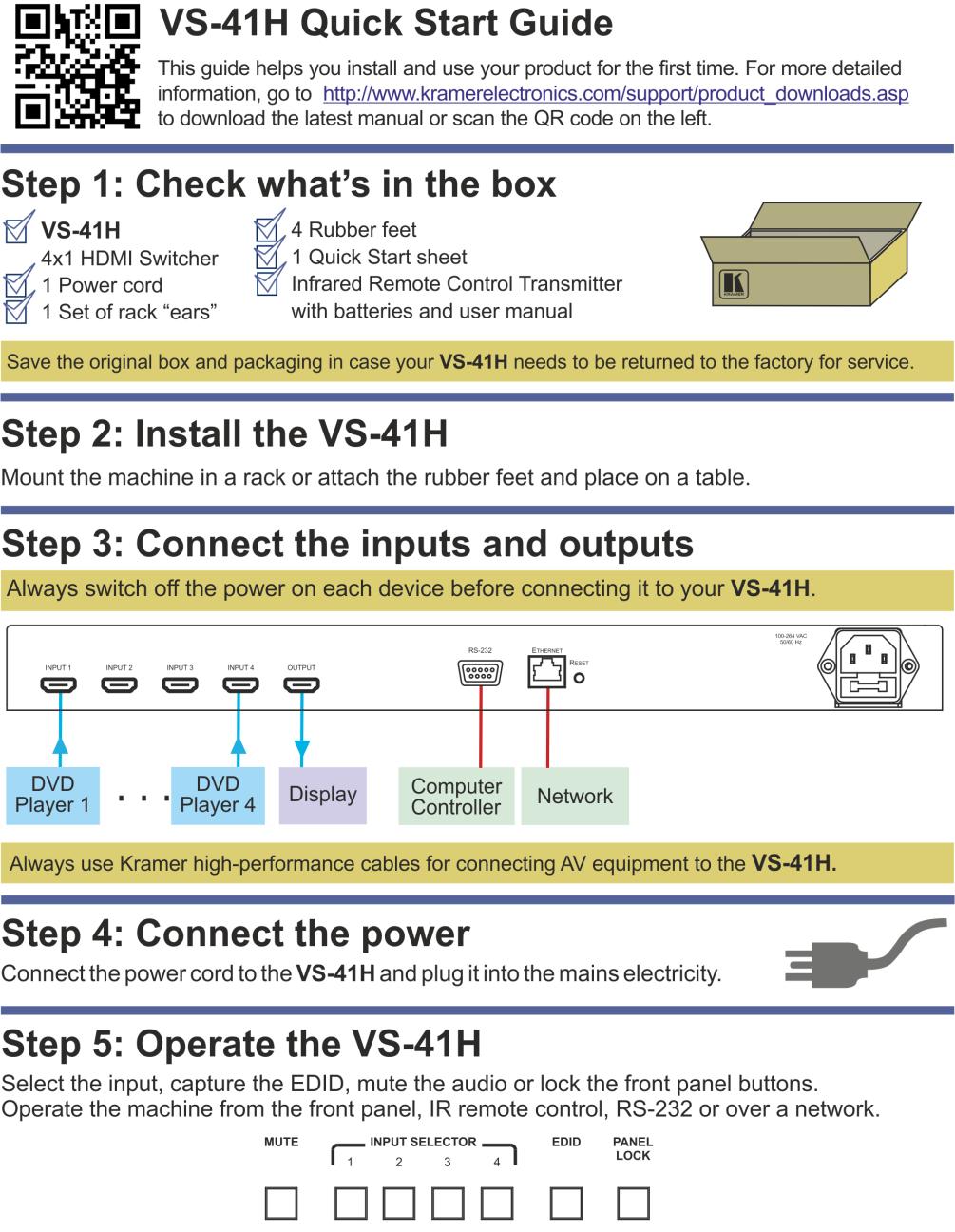
11 5 Connecting the VS-41H i To connect the VS-41H 4x1 HDMI Switcher (as illustrated in Figure 3), do the following: Always switch off the power to each device before connecting it to your VS-41H. After connecting your VS-41H, connect its power and then switch on the power to each device. 1. If required: Set the appropriate INPUTS to the DVD mode (see Section 6.1) Acquire the EDID (see Section 6.2) 2. Connect the HDMI sources as follows: You do not have to connect all the HDMI sources. Alternatively, you can connect a PC to any of the inputs and set those inputs to the PC mode (see Section 6.1) A multimedia player to INPUT 1 A set top box to INPUT 2 A DVD player to INPUT 3 A DVD player to INPUT 4 3. Connect the OUTPUT HDMI connector to an HDMI acceptor (for example, a plasma display). 4. If required, connect a PC and/or controller to the RS-232 port (see Section 6.3) and/or the Ethernet port (see Section 6.4). 5. Connect the power connector to the mains electricity (not shown in Figure 3). Press an INPUT SELECTOR button (from 1 to 4) to choose the HDMI input to route to the output. 8 VS-41H - Connecting the VS-41H

12 Figure 3: Connecting the VS-41H 4x1 HDMI Switcher VS-41H - Connecting the VS-41H 9
13 6 Operating the VS-41H This section describes: The PC mode and the DVD mode (see Section 6.1) How to acquire the EDID (see Section 6.2) How to control the machine via RS-232 (see Section 6.3) How to control the machine via the Ethernet port (see Section 6.4) 6.1 The PC and DVD Modes The VS-41H has two operation modes that can be set individually for each input: the PC mode (default) and the DVD mode: Use the PC mode when connecting one or more computers to the inputs using a DVI-to-HDMI converter cable For example, the Kramer HDMI-DVI gold-plated cable in various lengths (3, 6, 10 and 15 ). Use the DVD mode when connecting one or more DVDs to the inputs In the PC mode, an input always has access to the EDID (default or acquired) to prevent the computer from resetting if the output is not connected. In the DVD mode, an input only has access to the EDID when it is switched to the connected output. The PC mode and the DVD mode can be applied to a single unit or to several inputs. For example, if you want to connect computers to INPUTS 1 and 2, and DVD machines to INPUTS 3 and 4, set INPUTS 1 and 2 to the PC mode and INPUTS 3 and 4 to the DVD mode. To set the inputs to either the PC or DVD mode, do the following: 1. Turn off the VS-41H POWER. 2. Press the PANEL LOCK button while turning the POWER on again. 10 VS-41H - Operating the VS-41H
14 3. Keep pressing and holding the PANEL LOCK button for a few seconds and then release it. The LOCK button flashes. If an input button illuminates, this indicates that that input is set to the DVD mode. If an input button is not illuminated, this indicates that that input is set to the PC mode. 4. Press an input to toggle between the PC mode (input button not illuminated) and the DVD mode (input button illuminated). 5. To exit this mode, press the PANEL LOCK button. 6. Connect a computer to the input that is set to the PC mode and a DVD to the input that is set to the DVD mode. The following table summarizes the differences between the PC mode and the DVD mode: PC Mode The input is connected to a computer The EDID is available at all times (to prevent computer reset) The input EDID source is the default EDID or an acquired EDID (see Section 6.2) DVD Mode The input is connected to a multimedia application, such as a DVD, a set top box and so on The EDID is available only when the input and an output are connected The input EDID source is acquired directly from the connected output 6.2 Setting the EDID You can acquire or change the EDID (see Section 6.2.1) or reset the machine to the default EDID (see Section 6.2.2) Acquiring / Changing the EDID You can work with the default EDID or acquire or change an EDID via the connected output. Use the EDID button to acquire the output EDID information. VS-41H - Operating the VS-41H 11
15 To acquire or change the EDID of a new output display: 1. Connect the new output display device. 2. Press the EDID button. The INPUT buttons flash in sequence until the EDID is acquired Resetting the Default EDID To reset the default EDID, disconnect the output and repeat the steps in Section Connecting via the RS-232 Port You can connect to the VS-41H to a PC or RS-232 controller using the RS-232 connection. Note that a null-modem adapter/connection is not required. To connect to the VS-41H via RS-232: Connect the RS pin D-sub rear panel port on the VS-41H unit via a 9-wire straight cable (only pin 2 to pin 2, pin 3 to pin 3, and pin 5 to pin 5 need to be connected) to the RS pin D-sub port on your PC 6.4 Connecting via the Ethernet Port You can connect the VS-41H via the Ethernet, using a crossover cable (see Section 6.4.1) for direct connection to the PC or a straight through cable (see Section 6.4.2) for connection via a network hub or network router. After connecting the Ethernet port, install and configure your Ethernet Port. For detailed instructions, see the Ethernet Configuration (FC-11) guide.pdf file in the technical support section on our Web site: Connecting the Ethernet Port directly to a PC (Crossover Cable) You can connect the Ethernet port of the VS-41H to the Ethernet port on your PC, via a crossover cable with RJ-45 connectors. This type of connection is recommended for identification of the factory default IP Address of the VS-41H during the initial configuration. 12 VS-41H - Operating the VS-41H
 and click the Properties Button (see Figure 4).")
16 After connecting the Ethernet port, configure your PC as follows: 1. Right-click the My Network Places icon on your desktop. 2. Select Properties. 3. Right-click Local Area Connection Properties. 4. Select Properties. The Local Area Connection Properties window appears. 5. Select the Internet Protocol (TCP/IP) and click the Properties Button (see Figure 4). Figure 4: Local Area Connection Properties Window 6. Select Use the following IP Address, and fill in the details as shown in Figure Click OK. VS-41H - Operating the VS-41H 13
 You can connect the Ethernet port of the VS-41H to the Ethernet port on a network hub or network router, via a straight")
17 Figure 5: Internet Protocol (TCP/IP) Properties Window Connecting the Ethernet Port via a Network Hub (Straight- Through Cable) You can connect the Ethernet port of the VS-41H to the Ethernet port on a network hub or network router, via a straight through cable with RJ-45 connectors Configuring Several Units via the Ethernet Port To control several units via the Ethernet, connect each unit via the Ethernet port to the LAN port of your PC. Use your PC to initially configure the settings of each unit (see Section 6.4). 14 VS-41H - Operating the VS-41H
18 7 Technical Specifications INPUTS: OUTPUT: MAX. DATA RATE: COMPLIANCE WITH HDMI STANDARD: RESOLUTION: POWER SOURCE: CONTROLS: OPERATING TEMPERATURE: STORAGE TEMPERATURE: HUMIDITY: 4 HDMI connectors 1 HDMI connector Up to 6.75Gbps (2.25Gbps per graphic channel) Supports HDMI and HDCP Up to UXGA; 1080p V AC; 50/60Hz, 10VA Front panel buttons, infrared remote control transmitter, RS-232, Ethernet 0 to +55 C (32 to 131 F) -45 to +72 C (-49 to 162 F) 10% to 90%, RHL non-condensing DIMENSIONS: 19 x 7 x 1U (W, D, H) WEIGHT: ACCESSORIES: 2.5kg (5.5lbs) approx. Power cord, rack ears and IR remote control Specifications are subject to change without notice at VS-41H - Technical Specifications 15
19 8 Default Communication Parameters RS-232 Protocol 2000 Baud Rate: 9600 Data Bits: 8 Stop Bits: 1 Parity: None Command Format: HEX Example (Output 1 to Input 1): 0x01, 0x81, 0x81, 0x81 Ethernet IP Address: TCP Port Number: 5000 Network Mask: Default Gateway: VS-41H - Default Communication Parameters
20 9 Protocol 2000 Kramer Protocol 2000 for RS-232/RS-485 communication uses four bytes of information as defined below. MSB DESTINATION INSTRUCTION 0 D N5 N4 N3 N2 N1 N st byte INPUT 1 I6 I5 I4 I3 I2 I1 I nd byte OUTPUT 1 O6 O5 O4 O3 O2 O1 O rd byte MACHINE NUMBER 1 OVR X M4 M3 M2 M1 M th byte LSB 1st BYTE: Bit 7 Defined as 0. D DESTINATION : 0 - for sending information to the switchers (from the PC); 1 - for sending to the PC (from the switcher). N5 N0 INSTRUCTION The function that is to be performed by the switcher(s) is defined by the INSTRUCTION (6 bits). Similarly, if a function is performed via the machine s keyboard, then these bits are set with the INSTRUCTION NO., which was performed. The instruction codes are defined according to the table below (INSTRUCTION NO. is the value to be set for N5 N0). 2nd BYTE: Bit 7 Defined as 1. I6 I0 INPUT. When switching (ie. instruction codes 1 and 2), the INPUT (7 bits) is set as the input number which is to be switched. Similarly, if switching is done via the machine s front-panel, then these bits are set with the INPUT NUMBER which was switched. For other operations, these bits are defined according to the table. 3rd BYTE: Bit 7 Defined as 1. O6 O0 OUTPUT. When switching (ie. instruction codes 1 and 2), the OUTPUT (7 bits) is set as the output number which is to be switched. Similarly, if switching is done via the machine s front-panel, then these bits are set with the OUTPUT NUMBER which was switched. For other operations, these bits are defined according to the table. 4th BYTE: Bit 7 Defined as 1. Bit 5 Don t care. OVR Machine number override. M4 M0 MACHINE NUMBER. Used to address machines in a system via their machine numbers. When several machines are controlled from a single serial port, they are usually configured together with each machine having an individual machine number. If the OVR bit is set, then all machine numbers will accept (implement) the command, and the addressed machine will reply. For a single machine controlled via the serial port, always set M4 M0 = 1, and make sure that the machine itself is configured as MACHINE NUMBER = 1. i All the values in the table are decimal, unless otherwise stated VS-41H - Protocol
21 Instruction Codes for Protocol 2000 Instruction Definition for Specific Instruction Notes # Description Input Output 0 RESET VIDEO SWITCH VIDEO Set equal to video input which is to be switched (0 = disconnect) Set equal to video output which is to be switched (0 = to all the outputs) 2, 15 5 REQUEST STATUS OF A VIDEO OUTPUT Set as SETUP # 16 ERROR / BUSY For invalid / valid input (i.e. OUTPUT byte = 4 or OUTPUT byte = 5), This byte is set as the input # 24 INCREASE / DECREASE AUDIO PARAMETER Equal to input / output number whose parameter is to be increased / decreased (0 = all) 30 LOCK FRONT 0 - Panel unlocked PANEL 1 - Panel locked 61 IDENTIFY MACHINE 1 - video machine name 2 - audio machine name 3 - video software version 4 - audio software version 5 RS-422 controller name 6 RS-422 controller version 7 - remote control name 8 - remote software version 9 - Protocol 2000 revision 62 DEFINE MACHINE 1 - number of inputs 2 - number of outputs 3 - number of setups Equal to output number whose status is reqd 0 - error 1 - invalid instruction 2 - out of range 3 - machine busy 4 - invalid input 5 - valid input 4, 3 9, increase output decrease output 2 - increase left output 3 - decrease left output 4 - increase right output 5 - decrease right output 6 - increase input 7 - decrease input 8 - increase left input 9 - decrease left input 10 - increase right input 11 - decrease right input Request first 4 digits 1 - Request first suffix 2 - Request second suffix 3 - Request third suffix 10 - Request first prefix 11 - Request second prefix 12 - Request third prefix 1 - for video 2 - for audio 3 - for SDI 4 - for remote panel 5 - for RS-422 controller NOTES on the above table: NOTE 1 When the master switcher is reset, (e.g. when it is turned on), the reset code is sent to the PC. If this code is sent to the switchers, it will reset according to the present power-down settings. NOTE 2 These are bi-directional definitions. That is, if the switcher receives the code, it will perform the instruction; and if the instruction is performed (due to a keystroke operation on the front panel), then these codes are sent. For example, if the HEX code was sent from the PC, then the switcher (machine 3) will switch input 5 to output 8. If the user switched input 1 to output 7 via the front panel keypad, then the switcher will send HEX codes: to the PC. When the PC sends one of the commands in this group to the switcher, then, if the instruction is valid, the switcher replies by sending to the PC the same four bytes that it was sent (except for the first byte, where the DESTINATION bit is set high). NOTE 3 SETUP # 0 is the present setting. SETUP # 1 and higher are the settings saved in the switcher's memory, (i.e. those used for Store and Recall). NOTE 4 The reply to a "REQUEST" instruction is as follows: the same instruction and INPUT codes as were sent are returned, and the OUTPUT is assigned the value of the requested parameter. The replies to instructions 10 and 11 are as per the definitions in instructions 7 and 8 respectively. For example, if the present status of machine number 5 is breakaway setting, then the reply to the HEX code 0B would be HEX codes 4B VS-41H - Protocol 2000
22 NOTE 9 An error code is returned to the PC if an invalid instruction code was sent to the switcher, or if a parameter associated with the instruction is out of range (e.g. trying to save to a setup greater than the highest one, or trying to switch an input or output greater than the highest one defined). This code is also returned to the PC if an RS-232 instruction is sent while the machine is being programmed via the front panel. Reception of this code by the switcher is not valid. NOTE 13 This is a request to identify the switcher/s in the system. If the OUTPUT is set as 0, and the INPUT is set as 1, 2, 5 or 7, the machine will send its name. The reply is the decimal value of the INPUT and OUTPUT. For example, for a 2216, the reply to the request to send the audio machine name would be (HEX codes): 7D (i.e. 128dec+ 22dec for 2nd byte, and 128dec+ 16dec for 3rd byte). If the request for identification is sent with the INPUT set as 3 or 4, the appropriate machine will send its software version number. Again, the reply would be the decimal value of the INPUT and OUTPUT - the INPUT representing the number in front of the decimal point, and the OUTPUT representing the number after it. For example, for version 3.5, the reply to the request to send the version number would be (HEX codes): 7D (i.e. 128dec+ 3dec for 2nd byte, 128dec+ 5dec for 3rd byte). If the OUTPUT is set as 1, then the ASCII coding of the lettering following the machine s name is sent. For example, for the VS-7588YC, the reply to the request to send the first suffix would be (HEX codes): 7D D9 C3 81 (i.e. 128dec+ ASCII for Y ; 128dec+ ASCII for C ). NOTE 14 The number of inputs and outputs refers to the specific machine which is being addressed, not to the system. For example, if six 16X16 matrices are configured to make a 48X32 system (48 inputs, 32 outputs), the reply to the HEX code 3E (i.e. request the number of outputs) would be HEX codes 7E i.e. 16 outputs NOTE 15 When the OVR bit (4th byte) is set, then the video commands have universal meaning. For example, instruction 1 (SWITCH VIDEO) will cause all units (including audio, data, etc.) to switch. Similarly, if a machine is in FOLLOW mode, it will perform any video instruction. NOTE 24 Further information needed in instructions 21, 22, 25 and 26, is sent using instruction 42 which is sent prior to the instruction. For example, to request the audio gain value of right input # 9, send hex codes 2A and then send HEX codes To set MIX mode, send hex codes 2A and then send HEX codes 16 NOTE 25 For units which detect the validity of the video inputs, Instruction 16 will be sent whenever the unit detects a change in the state of an input (in real-time). For example, if input 3 is detected as invalid, the unit will send the HEX codes If input 7 is detected as valid, then the unit will send HEX codes VS-41H - Protocol

23 20 VS-41H - Protocol 2000
24 For the latest information on our products and a list of Kramer distributors, visit our Web site where updates to this user manual may be found. We welcome your questions, comments, and feedback. Web site: info@kramerel.com! SAFETY WARNING Disconnect the unit from the power supply before opening and servicing P/N: Rev: 7
USER MANUAL. VS-88H 8x8 HDMI Matrix Switcher MODEL: P/N: Rev 5
 KRAMER ELECTRONICS LTD. USER MANUAL MODEL: VS-88H 8x8 HDMI Matrix Switcher P/N: 2900-000654 Rev 5 Contents 1 Introduction 1 2 Getting Started 2 2.1 Achieving the Best Performance 2 2.2 Safety Instructions
USER MANUAL. VM-28H 2 Input 1:8 HDMI Distributor. VM-216H 2 Input 1:16 HDMI Distributor MODEL: P/N: Rev 5
 KRAMER ELECTRONICS LTD. USER MANUAL MODEL: VM-28H 2 Input 1:8 HDMI Distributor VM-216H 2 Input 1:16 HDMI Distributor P/N: 2900-000662 Rev 5 Contents 1 Introduction 1 2 Getting Started 2 2.1 Achieving
KRAMER ELECTRONICS LTD. USER MANUAL MODEL: VM-24H 2 Input 1:4 HDMI Distributor. P/N: Rev 4
 KRAMER ELECTRONICS LTD. USER MANUAL MODEL: VM-24H 2 Input 1:4 HDMI Distributor P/N: 2900-000664 Rev 4 Contents 1 Introduction 1 2 Getting Started 2 2.1 Achieving the Best Performance 2 2.2 Safety Instructions
KRAMER ELECTRONICS LTD. USER MANUAL MODEL: VS-41HC 4x1 HDMI Switcher. P/N: Rev 4
 KRAMER ELECTRONICS LTD. USER MANUAL MODEL: VS-41HC 4x1 HDMI Switcher P/N: 2900-000423 Rev 4 Contents 1 Introduction 1 2 Getting Started 2 2.1 Achieving the Best Performance 2 2.2 Safety Instructions 3
USER MANUAL. VS-311H Automatic HDMI/Audio Switcher MODEL: P/N: Rev 3
 KRAMER ELECTRONICS LTD. USER MANUAL MODEL: VS-311H Automatic HDMI/Audio Switcher P/N: 2900-000666 Rev 3 Contents 1 Introduction 1 2 Getting Started 2 2.1 Achieving the Best Performance 2 2.2 Safety Instructions
USER MANUAL. VS-88HDCPxl 8x8 DVI Matrix Switcher MODEL: P/N: Rev 9
 KRAMER ELECTRONICS LTD. USER MANUAL MODEL: VS-88HDCPxl 8x8 DVI Matrix Switcher P/N: 2900-300016 Rev 9 Contents 1 Introduction 1 2 Getting Started 2 2.1 Achieving the Best Performance 2 2.2 Safety Instructions
USER MANUAL. VM-2Hxl 1:2 HDMI Distributor MODEL: P/N: Rev 3
 KRAMER ELECTRONICS LTD. USER MANUAL MODEL: VM-2Hxl 1:2 HDMI Distributor P/N: 2900-000672 Rev 3 Contents 1 Introduction 1 2 Getting Started 2 2.1 Achieving the Best Performance 2 2.2 Safety Instructions
Kramer Electronics, Ltd. USER MANUAL. Models: VM-8H, 1:8 HDMI Distributor VM-16H, 1:16 HDMI Distributor
 Kramer Electronics, Ltd. USER MANUAL Models: VM-8H, 1:8 HDMI Distributor VM-16H, 1:16 HDMI Distributor Contents Contents 1 Introduction 1 2 Getting Started 1 2.1 Quick Start 2 3 Overview 3 3.1 Recommendations
KRAMER ELECTRONICS LTD. USER MANUAL MODEL: VS-161H 16x1 HDMI Switcher. P/N: Rev 6
 KRAMER ELECTRONICS LTD. USER MANUAL MODEL: VS-161H 16x1 HDMI Switcher P/N: 2900-000665 Rev 6 Contents 1 Introduction 1 2 Getting Started 2 2.1 Achieving the Best Performance 2 3 Overview 3 3.1 About HDMI
USER MANUAL. VS-21HDCP-IR 2x1 DVI Switcher MODEL: P/N: Rev 5
 KRAMER ELECTRONICS LTD. USER MANUAL MODEL: VS-21HDCP-IR 2x1 DVI Switcher P/N: 2900-000556 Rev 5 Contents 1 Introduction 1 2 Getting Started 2 2.1 Achieving the Best Performance 2 2.2 Safety Instructions
USER MANUAL. VS Port RS-422 Matrix Switcher MODEL: P/N: Rev 5
 KRAMER ELECTRONICS LTD. USER MANUAL MODEL: VS-4228 8-Port RS-422 Matrix Switcher P/N: 2900-0033 Rev 5 Contents 1 Introduction 1 2 Getting Started 2 2.1 Achieving the Best Performance 2 2.2 Safety Instructions
KRAMER ELECTRONICS LTD. USER MANUAL MODEL: VS-401USB 4x1 USB Switcher. P/N: Rev 1
 KRAMER ELECTRONICS LTD. USER MANUAL MODEL: VS-401USB 4x1 USB Switcher P/N: 2900-300029 Rev 1 Contents 1 Introduction 1 2 Getting Started 2 2.1 Achieving the Best Performance 2 2.2 Recycling Kramer Products
USER MANUAL. VP-311DVI Automatic DVI/Audio Switcher MODEL: P/N: Rev 3
 KRAMER ELECTRONICS LTD. USER MANUAL MODEL: VP-311DVI Automatic DVI/Audio Switcher P/N: 2900-000120 Rev 3 Contents 1 Introduction 1 2 Getting Started 2 2.1 Achieving the Best Performance 2 2.2 Safety Instructions
USER MANUAL. VM-2HDCPxl 1:2 DVI Distributor MODEL: P/N: Rev 3
 KRAMER ELECTRONICS LTD. USER MANUAL MODEL: VM-2HDCPxl 1:2 DVI Distributor P/N: 2900-000510 Rev 3 Contents 1 Introduction 1 2 Getting Started 2 2.1 Achieving the Best Performance 2 2.2 Safety Instructions
USER MANUAL. 671T DVI Optical Transmitter. 671R DVI Optical Receiver MODEL: P/N: Rev 4
 KRAMER ELECTRONICS LTD. USER MANUAL MODEL: 671T DVI Optical Transmitter 671R DVI Optical Receiver P/N: 2900-000484 Rev 4 Contents 1 Introduction 1 2 Getting Started 2 2.1 Achieving the Best Performance
USER MANUAL. SL-1N Master Room Controller MODEL: P/N: Rev 1
 KRAMER ELECTRONICS LTD. USER MANUAL MODEL: SL-1N Master Room Controller P/N: 2900-300399 Rev 1 Contents 1 Introduction 1 2 Getting Started 2 2.1 Achieving the Best Performance 2 2.2 Safety Instructions
USER MANUAL. PT-1C EDID Processor MODEL: P/N: Rev 3
 KRAMER ELECTRONICS LTD. USER MANUAL MODEL: PT-1C EDID Processor P/N: 2900-300276 Rev 3 Contents 1 Introduction 1 2 Getting Started 2 2.1 Achieving the Best Performance 2 2.2 Recycling Kramer Products
USER MANUAL. RC-43SL 6-Button Room Controller MODEL: P/N: Rev 1.
 USER MANUAL MODEL: RC-43SL 6-Button Room Controller P/N: 2900-300450 Rev 1 www.kramerav.com Contents 1 Introduction 1 2 Getting Started 2 2.1 Achieving the Best Performance 2 2.2 Safety Instructions
KRAMER ELECTRONICS LTD. USER MANUAL MODEL: VM-73 Multiformat 1:3 Distribution Amplifier. P/N: Rev 3
 KRAMER ELECTRONICS LTD. USER MANUAL MODEL: VM-73 Multiformat 1:3 Distribution Amplifier P/N: 2900-000544 Rev 3 Contents 1 Introduction 1 2 Getting Started 2 2.1 Achieving the Best Performance 2 2.2 Recycling
USER MANUAL. SL-10 Master Room Controller MODEL: P/N: Rev 4
 KRAMER ELECTRONICS LTD. USER MANUAL MODEL: SL-10 Master Room Controller P/N: 2900-000581 Rev 4 Contents 1 Introduction 1 2 Getting Started 2 2.1 Achieving the Best Performance 2 2.2 Safety Instructions
USER MANUAL. RC-43T Remote Controller MODEL: P/N: Rev 3
 KRAMER ELECTRONICS LTD. USER MANUAL MODEL: RC-43T Remote Controller P/N: 2900-300301 Rev 3 Contents 1 Introduction 1 2 Getting Started 2 2.1 Achieving the Best Performance 2 2.2 Safety Instructions 3
USER MANUAL. VA-1USB-T USB Transmitter. VA-1USB-R USB Receiver MODELS: P/N: Rev 3
 KRAMER ELECTRONICS LTD. USER MANUAL MODELS: VA-1USB-T USB Transmitter VA-1USB-R USB Receiver P/N: 2900-300209 Rev 3 Contents 1 Introduction 1 2 Getting Started 2 2.1 Achieving the Best Performance 2 2.2
USER MANUAL. TP-580Txr HDMI Line Transmitter. TP-580Rxr HDMI Line Receiver MODELS: P/N: Rev 5
 KRAMER ELECTRONICS LTD. USER MANUAL MODELS: TP-580Txr HDMI Line Transmitter TP-580Rxr HDMI Line Receiver P/N: 2900-300088 Rev 5 Contents 1 Introduction 1 2 Getting Started 2 2.1 Achieving the Best Performance
USER MANUAL. PT-101UHD HDMI Repeater MODEL: P/N: Rev 3.
 USER MANUAL MODEL: PT-101UHD HDMI Repeater P/N: 2900-300492 Rev 3 www.kramerav.com Contents 1 Introduction 1 2 Getting Started 2 2.1 Achieving the Best Performance 2 2.2 Safety Instructions 2 2.3 Recycling
USER MANUAL. RC-43SL 6-Button Room Controller MODEL: P/N: Rev 3.
 USER MANUAL MODEL: RC-43SL 6-Button Room Controller P/N: 2900-300450 Rev 3 www.kramerav.com Contents 1 Introduction 1 2 Getting Started 2 2.1 Achieving the Best Performance 2 2.2 Safety Instructions
KRAMER ELECTRONICS LTD. USER MANUAL MODEL: VA-1VGAN EDID Capture. P/N: Rev 2
 KRAMER ELECTRONICS LTD. USER MANUAL MODEL: VA-1VGAN EDID Capture P/N: 2900-000513 Rev 2 Contents 1 Introduction 1 2 Getting Started 2 2.1 Achieving the Best Performance 2 2.2 Recycling Kramer Products
USER MANUAL. RS-232 Extender MODEL: P/N: Rev 1
 USER MANUAL MODEL: RS-232 Extender P/N: 2900-300284 Rev 1 Contents 1 Introduction 1 2 Getting Started 2 2.1 Achieving the Best Performance 2 2.2 Safety Instructions 3 2.3 Recycling Kramer Products 3 3
KRAMER ELECTRONICS LTD. USER MANUAL MODEL: 905xl Power Amplifier. P/N: Rev 3
 KRAMER ELECTRONICS LTD. USER MANUAL MODEL: 905xl Power Amplifier P/N: 2900-300196 Rev 3 Contents 1 Introduction 1 2 Getting Started 2 2.1 Achieving the Best Performance 2 2.2 Safety Instructions 2 2.3
USER MANUAL. PT-580T HDMI Line Transmitter. TP-580T HDMI Line Transmitter. TP-580R HDMI Line Receiver MODELS: P/N: Rev 3
 KRAMER ELECTRONICS LTD. USER MANUAL MODELS: PT-580T HDMI Line Transmitter TP-580T HDMI Line Transmitter TP-580R HDMI Line Receiver P/N: 2900-300340 Rev 3 Contents 1 Introduction 1 2 Getting Started 2
USER MANUAL. PT-5T/R IR Extender/Repeater MODEL: P/N: Rev 3
 KRAMER ELECTRONICS LTD. USER MANUAL MODEL: PT-5T/R IR Extender/Repeater P/N: 2900-300010 Rev 3 Contents 1 Introduction 1 2 Getting Started 2 2.1 Achieving the Best Performance 2 2.2 Safety Instructions
USER MANUAL V/100V Power Amplifier MODEL: P/N: Rev 4
 KRAMER ELECTRONICS LTD. USER MANUAL MODEL: 920 70V/100V Power Amplifier P/N: 2900-300308 Rev 4 Contents 1 Introduction 1 2 Getting Started 2 2.1 Achieving the Best Performance 2 2.2 Safety Instructions
KRAMER ELECTRONICS LTD. USER MANUAL MODELS: TP-580T HDMI Line Transmitter. TP-580R HDMI Line Receiver. P/N: Rev 2
 KRAMER ELECTRONICS LTD. USER MANUAL MODELS: TP-580T HDMI Line Transmitter TP-580R HDMI Line Receiver P/N: 2900-300034 Rev 2 Contents 1 Introduction 1 2 Getting Started 2 2.1 Achieving the Best Performance
USER MANUAL. VP-211K Automatic UXGA / Audio Switcher MODEL: P/N: Rev 3
 KRAMER ELECTRONICS LTD. USER MANUAL MODEL: VP-211K Automatic UXGA / Audio Switcher P/N: 2900-000414 Rev 3 Contents 1 Introduction 1 2 Getting Started 2 2.1 Achieving the Best Performance 2 2.2 Safety
KRAMER ELECTRONICS LTD. USER MANUAL MODEL: VP-4x8 4x8 VGA/UXGA Matrix Switcher. P/N: Rev 3
 KRAMER ELECTRONICS LTD. USER MANUAL MODEL: VP-4x8 4x8 VGA/UXGA Matrix Switcher P/N: 2900-000372 Rev 3 Contents 1 Introduction 1 2 Getting Started 2 2.1 Achieving the Best Performance 2 2.2 Recycling Kramer
USER MANUAL RC-76M/RC-712M MODEL: P/N: Rev 3
 KRAMER ELECTRONICS LTD. USER MANUAL MODEL: RC-76M/RC-712M P/N: 2900-300329 Rev 3 Contents 1 Introduction 1 2 Getting Started 2 2.1 Achieving the Best Performance 2 2.2 Safety Instructions 3 2.3 Recycling
USER MANUAL. RC-74DL Master Room Controller MODEL: P/N: Rev 4
 KRAMER ELECTRONICS LTD. USER MANUAL MODEL: RC-74DL Master Room Controller P/N: 2900-000691 Rev 4 Contents 1 Introduction 1 2 Getting Started 2 2.1 Achieving the Best Performance 2 2.2 Safety Instructions
USER MANUAL. RC-76R/RC-78R Room Controllers MODEL: P/N: Rev 2
 KRAMER ELECTRONICS LTD. USER MANUAL MODEL: RC-76R/RC-78R Room Controllers P/N: 2900-300253 Rev 2 Contents 1 Introduction 1 2 Getting Started 2 2.1 Achieving the Best Performance 2 2.2 Safety Instructions
USER MANUAL. TP-780T HDMI Line Transmitter + POE TP-780R HDMI Line Receiver + POE MODELS: P/N: Rev 2.
 USER MANUAL MODELS: TP-780T HDMI Line Transmitter + POE TP-780R HDMI Line Receiver + POE P/N: 2900-300575 Rev 2 www.kramerav.com Contents 1 Introduction 1 2 Getting Started 2 2.1 Achieving the Best Performance
Kramer Electronics, Ltd. USER MANUAL. Model: TP Channel UXGA/Audio/RS-232 to CAT 5 Transmitter
 Kramer Electronics, Ltd. USER MANUAL Model: TP-185 8 Channel UXGA/Audio/RS-232 to CAT 5 Transmitter Contents Contents 1 Introduction 1 2 Getting Started 1 2.1 Quick Start 2 3 Overview 3 3.1 Shielded Twisted
KRAMER ELECTRONICS LTD. USER MANUAL MODEL: VS-211HA Automatic HDMI Standby Switcher. P/N: Rev 3
 KRAMER ELECTRONICS LTD. USER MANUAL MODEL: VS-211HA Automatic HDMI Standby Switcher P/N: 2900-300378 Rev 3 Contents 1 Introduction 1 2 Getting Started 2 2.1 Achieving the Best Performance 2 2.2 Safety
KRAMER ELECTRONICS LTD. USER MANUAL MODEL: RC-74DL Master Room Controller. P/N: Rev 5
 KRAMER ELECTRONICS LTD. USER MANUAL MODEL: RC-74DL Master Room Controller P/N: 2900-000691 Rev 5 Contents 1 Introduction 1 2 Getting Started 2 2.1 Achieving the Best Performance 2 2.2 Safety Instructions
KRAMER ELECTRONICS LTD. USER MANUAL MODEL: RC-76R/RC-78R Room Controllers. P/N: Rev 5
 KRAMER ELECTRONICS LTD. USER MANUAL MODEL: RC-76R/RC-78R Room Controllers P/N: 2900-300253 Rev 5 Contents 1 Introduction 1 2 Getting Started 2 2.1 Achieving the Best Performance 2 2.2 Safety Instructions
KRAMER ELECTRONICS LTD. USER MANUAL MODELS: TP-125xl UXGA/Audio/Data Line Transmitter. TP-126xl UXGA/Audio/Data Line Receiver. P/N: Rev 4
 KRAMER ELECTRONICS LTD. USER MANUAL MODELS: TP-125xl UXGA/Audio/Data Line Transmitter TP-126xl UXGA/Audio/Data Line Receiver P/N: 2900-300206 Rev 4 Contents 1 Introduction 1 2 Getting Started 2 2.1 Achieving
USER MANUAL. 602T Two-fiber Detachable Optical DVI Transmitter 602R. DVI Receiver MODELS: P/N: Rev 3
 KRAMER ELECTRONICS LTD. USER MANUAL MODELS: 602T Two-fiber Detachable Optical DVI Transmitter 602R Two-fiber Detachable Optical DVI Receiver P/N: 2900-000646 Rev 3 Contents 1 Introduction 1 2 Getting
KRAMER ELECTRONICS LTD. USER MANUAL MODEL: VS Port RS-422 Matrix Switcher. P/N: Rev 4
 KRAMER ELECTRONICS LTD. USER MANUAL MODEL: VS-4228 8-Port RS-422 Matrix Switcher P/N: 2900-002033 Rev 4 6 Contents 1 Introduction 1 2 Getting Started 2 2.1 Achieving the Best Performance 2 3 Overview
USER MANUAL. 614T One-Fiber Detachable Optical DVI Transmitter. 614R One-Fiber Detachable Optical DVI Receiver MODELS: P/N: Rev 5
 KRAMER ELECTRONICS LTD. USER MANUAL MODELS: 614T One-Fiber Detachable Optical DVI Transmitter 614R One-Fiber Detachable Optical DVI Receiver P/N: 2900-300249 Rev 5 Contents 1 Introduction 1 2 Getting
USER MANUAL. TP-780TXR Extended Range HDMI Line Transmitter + POE TP-780RXR Extended Range HDMI Line Receiver + POE MODELS: P/N: Rev 2
 USER MANUAL MODELS: TP-780TXR Extended Range HDMI Line Transmitter + POE TP-780RXR Extended Range HDMI Line Receiver + POE P/N: 2900-300576 Rev 2 www.kramerav.com Contents 1 Introduction 1 2 Getting
USER MANUAL. VS-808TP 8x8 Twisted Pair Matrix Switcher MODEL: P/N: Rev 2
 KRAMER ELECTRONICS LTD. USER MANUAL MODEL: VS-808TP 8x8 Twisted Pair Matrix Switcher P/N: 2900-300147 Rev 2 Contents 1 Introduction 1 2 Getting Started 2 2.1 Achieving the Best Performance 2 2.2 Safety
KRAMER ELECTRONICS LTD. USER MANUAL MODEL: 622T Dual Link DVI Optical Transmitter. 622R Dual Link DVI Optical Receiver. P/N: Rev 4
 KRAMER ELECTRONICS LTD. USER MANUAL MODEL: 622T Dual Link DVI Optical Transmitter 622R Dual Link DVI Optical Receiver P/N: 2900-000104 Rev 4 Contents 1 Introduction 1 2 Getting Started 2 2.1 Achieving
USER MANUAL. 621T DVI Optical Transmitter. 621R DVI Optical Receiver MODEL: P/N: Rev 8
 KRAMER ELECTRONICS LTD. USER MANUAL MODEL: 621T DVI Optical Transmitter 621R DVI Optical Receiver P/N: 2900-000103 Rev 8 Contents 1 Introduction 1 2 Getting Started 2 2.1 Achieving the Best Performance
USER MANUAL. TP-145 XGA/Audio/Data Line Transmitter. TP-146 UXGA/Audio/Data Line Receiver MODELS: P/N: Rev 3
 KRAMER ELECTRONICS LTD. USER MANUAL MODELS: TP-145 XGA/Audio/Data Line Transmitter TP-146 UXGA/Audio/Data Line Receiver P/N: 2900-000607 Rev 3 Contents 1 Introduction 1 2 Getting Started 2 2.1 Achieving
KRAMER ELECTRONICS LTD. USER MANUAL MODEL: VS-801USB 8x1 USB Switcher. P/N: Rev 3
 KRAMER ELECTRONICS LTD. USER MANUAL MODEL: VS-801USB 8x1 USB Switcher P/N: 2900-300030 Rev 3 Contents 1 Introduction 1 2 Getting Started 2 2.1 Achieving the Best Performance 2 3 Overview 3 3.1 Defining
USER MANUAL VM-4HC 1:4 HDMI DA MODEL: P/N: Rev 4
 KRAMER ELECTRONICS LTD. USER MANUAL MODEL: VM-4HC 1:4 HDMI DA P/N: 2900-000716 Rev 4 Contents 1 Introduction 1 2 Getting Started 2 2.1 Achieving the Best Performance 2 2.2 Safety Instructions 3 2.3 Recycling
USER MANUAL VM-2HN 1:2 HDMI DA MODEL: P/N: Rev 3
 KRAMER ELECTRONICS LTD. USER MANUAL MODEL: VM-2HN 1:2 HDMI DA P/N: 2900-300381 Rev 3 Contents 1 Introduction 1 2 Getting Started 2 2.1 Achieving the Best Performance 2 2.2 Safety Instructions 3 2.3 Recycling
KRAMER ELECTRONICS LTD. USER MANUAL MODEL: VS-808TP 8x8 Twisted Pair Matrix Switcher. P/N: Rev 1
 KRAMER ELECTRONICS LTD. USER MANUAL MODEL: VS-808TP 8x8 Twisted Pair Matrix Switcher P/N: 2900-300147 Rev 1 Contents 1 Introduction 1 2 Getting Started 2 2.1 Achieving the Best Performance 2 2.2 Using
KRAMER ELECTRONICS LTD. USER MANUAL MODEL: TP-576 HDMI/CAT 5 Line Driver. P/N: Rev 5
 KRAMER ELECTRONICS LTD. USER MANUAL MODEL: TP-576 HDMI/CAT 5 Line Driver P/N: 2900-000760 Rev 5 Contents 1 Introduction 1 2 Getting Started 2 2.1 Achieving the Best Performance 2 2.2 Safety Instructions
USER MANUAL VM-4HN 1:4 HDMI DA MODEL: P/N: Rev 4
 KRAMER ELECTRONICS LTD. USER MANUAL MODEL: VM-4HN 1:4 HDMI DA P/N: 2900-300106 Rev 4 Contents 1 Introduction 1 2 Getting Started 2 2.1 Achieving the Best Performance 2 2.2 Safety Instructions 3 2.3 Recycling
Kramer Electronics, Ltd. USER MANUAL. Model: VS-81H. 8x1 HDMI Switcher
 Kramer Electronics, Ltd. USER MANUAL Model: VS-81H 8x1 HDMI Switcher Contents Contents 1 Introduction 1 2 Getting Started 1 2.1 Quick Start 2 3 Overview 3 3.1 Defining EDID 3 3.2 About HDMI 4 3.3 About
USER MANUAL. VM-400HDCP 1:4 DVI Distributor MODEL: P/N: Rev 2
 KRAMER ELECTRONICS LTD. USER MANUAL MODEL: VM-400HDCP 1:4 DVI Distributor P/N: 2900-300054 Rev 2 Contents 1 Introduction 1 2 Getting Started 2 2.1 Achieving the Best Performance 2 2.2 Safety Instructions
KRAMER ELECTRONICS LTD. USER MANUAL MODEL: VA-2H EDID Reader-Emulator. P/N: Rev 3
 KRAMER ELECTRONICS LTD. USER MANUAL MODEL: VA-2H EDID Reader-Emulator P/N: 2900-000677 Rev 3 Contents 1 Introduction 1 2 Getting Started 2 2.1 Achieving the Best Performance 2 3 Overview 3 3.1 Defining
USER MANUAL. VM-114H2C 2 Input 1:4 HDMI DA/2x CAT5 Outputs MODEL: P/N: Rev 9
 KRAMER ELECTRONICS LTD. USER MANUAL MODEL: VM-114H2C 2 Input 1:4 HDMI DA/2x CAT5 Outputs P/N: 2900-000644 Rev 9 Contents 1 Introduction 1 2 Getting Started 2 2.1 Achieving the Best Performance 2 2.2 Safety
Kramer Electronics, Ltd.
 Kramer Electronics, Ltd. Preliminary USER MANUAL Model: VS-41H 4x1 HDMI Switcher Contents Contents 1 Introduction 1 2 Getting Started 1 2.1 Quick Start 2 3 Overview 3 3.1 Defining EDID 3 3.2 About HDMI
USER MANUAL. KDS-EN3 HD Video Encoder/Streamer. KDS-DEC3 HD Video Decoder MODELS: P/N: Rev 3
 KRAMER ELECTRONICS LTD. USER MANUAL MODELS: KDS-EN3 HD Video Encoder/Streamer KDS-DEC3 HD Video Decoder P/N: 2900-300375 Rev 3 Contents 1 Introduction 1 2 Getting Started 2 2.1 Achieving the Best Performance
USER MANUAL. FC-49 DVI / Audio to HDMI Converter MODEL: P/N: Rev 6
 KRAMER ELECTRONICS LTD. USER MANUAL MODEL: FC-49 DVI / Audio to HDMI Converter P/N: 2900-000286 Rev 6 Contents 1 Introduction 1 2 Getting Started 2 2.1 Achieving the Best Performance 2 2.2 Safety Instructions
Kramer Electronics, Ltd. USER MANUAL. Model: VM-24HDCP. 2 Input 1:4 DVI Distributor
 Kramer Electronics, Ltd. USER MANUAL Model: VM-24HDCP 2 Input 1:4 DVI Distributor Contents Contents 1 Introduction 1 2 Getting Started 1 2.1 Quick Start 2 3 Overview 3 3.1 About HDCP 3 3.2 Defining EDID
Kramer Electronics, Ltd.
 Kramer Electronics, Ltd. Preliminary USER MANUAL Model: VA-1VGAN EDID Capture Introduction Contents 1 Introduction 1 2 Getting Started 1 2.1 Quick Start 2 3 Overview 3 3.1 Defining EDID 4 4 Your VA-1VGAN
USER MANUAL. RC-54DL KNET Auxiliary Control Panel MODEL: P/N: Rev 2
 KRAMER ELECTRONICS LTD. USER MANUAL MODEL: RC-54DL KNET Auxiliary Control Panel P/N: 2900-300130 Rev 2 Contents 1 Introduction 1 2 Getting Started 2 2.1 Achieving the Best Performance 2 3 Overview 3 3.1
Kramer Electronics, Ltd.
 Kramer Electronics, Ltd. Preliminary USER MANUAL Model: FC-50 RS-232 Range Extender Contents Contents 1 Introduction 1 2 Getting Started 1 2.1 Quick Start 2 3 Overview 3 3.1 About the Power Connect Feature
USER MANUAL. TP-780TXR Extended Range HDMI Line Transmitter + POE TP-780RXR Extended Range HDMI Line Receiver + POE MODELS: P/N: Rev 3
 USER MANUAL MODELS: TP-780TXR Extended Range HDMI Line Transmitter + POE TP-780RXR Extended Range HDMI Line Receiver + POE P/N: 2900-300576 Rev 3 www.kramerav.com Contents 1 Introduction 1 2 Getting
KRAMER ELECTRONICS LTD. USER MANUAL MODEL: VA-1VGAxl EDID Capture/Emulator. P/N: Rev 2
 KRAMER ELECTRONICS LTD. USER MANUAL MODEL: VA-1VGAxl EDID Capture/Emulator P/N: 2900-300011 Rev 2 Contents 1 Introduction 1 2 Getting Started 2 2.1 Achieving the Best Performance 2 3 Overview 3 3.1 Defining
KRAMER ELECTRONICS LTD. USER MANUAL MODELS: TP-121EDID, XGA /Audio Line Transmitter TP-125EDID, XGA. PT-110EDID, XGA Line Transmitter
 KRAMER ELECTRONICS LTD. USER MANUAL MODELS: TP-121EDID, XGA /Audio Line Transmitter TP-123EDID, XGA /Audio/Data Line Transmitter TP-125EDID, XGA /Audio/Data Line Transmitter PT-110EDID, XGA Line Transmitter
WAV-5 WAV-5C WAV-3 WA-1H WAV-1R WAV-1RP
 KRAMER ELECTRONICS LTD. USER MANUAL MODELS: WAV-5 WAV-5C WAV-3 WA-1H WAV-1R WAV-1RP Wall Plate Series P/N: 2900-300124 Rev 2 Contents 1 Introduction 1 2 Getting Started 2 2.1 Achieving the Best Performance
Kramer Electronics, Ltd. USER MANUAL. Model: VM-24H. 2 Input 1:4 HDMI Distributor
 Kramer Electronics, Ltd. USER MANUAL Model: VM-24H 2 Input 1:4 HDMI Distributor Contents Contents 1 Introduction 1 2 Getting Started 1 2.1 Quick Start 2 3 Overview 3 3.1 About HDMI 3 3.2 Defining EDID
KRAMER ELECTRONICS LTD. USER MANUAL MODELS: WP-110, XGA Line Transmitter. PT-120, XGA Line Receiver. TP-120, XGA Line Receiver. P/N: Rev 1
 KRAMER ELECTRONICS LTD. USER MANUAL MODELS: WP-110, XGA Line Transmitter PT-120, XGA Line Receiver TP-120, XGA Line Receiver P/N: 2900-300180 Rev 1 Contents 1 Introduction 1 2 Getting Started 2 2.1 Achieving
Kramer Electronics, Ltd. USER MANUAL. Model: PL-8. Low Voltage Relay Controller
 Kramer Electronics, Ltd. USER MANUAL Model: PL-8 Low Voltage Relay Controller Contents Contents 1 Introduction 1 2 Getting Started 1 2.1 Quick Start 2 3 Overview 2 4 Your PL-8 Low Voltage Relay Controller
Kramer Electronics, Ltd. USER MANUAL. Model: VA-1VGA. EDID Capture
 Kramer Electronics, Ltd. USER MANUAL Model: VA-1VGA EDID Capture Contents Contents 1 Introduction 1 2 Getting Started 1 2.1 Quick Start 2 3 Overview 3 3.1 Defining EDID 3 4 Your VA-1VGA EDID Capture 4
Kramer Electronics, Ltd. USER MANUAL VM-24HD. 2 x 1:4 HD/SD SDI DA
 Kramer Electronics, Ltd. USER MANUAL VM-24HD 2 x 1:4 HD/SD SDI DA Contents Contents 1 Introduction 1 2 Getting Started 1 2.1 Quick Start 2 3 Overview 3 4 Your VM-24HD 2 x 1:4 HD/SD SDI DA 4 5 Connecting
Kramer Electronics, Ltd.
 Kramer Electronics, Ltd. Preliminary USER MANUAL Model: VM-12HDCP 1:12 DVI Distributor Contents Contents 1 Introduction 1 2 Getting Started 1 2.1 Quick Start 2 3 Overview 3 3.1 About HDCP 4 3.2 Defining
USER MANUAL MODEL: KWC-1 Wireless Charging Spot
 USER MANUAL MODEL: KWC-1 Wireless Charging Spot P/N: 2900-300504 Rev 6 www.kramerav.com Contents 1 Introduction 1 2 Getting Started 2 2.1 Achieving the Best Performance 2 2.2 Recycling Kramer Products
Kramer Electronics, Ltd. USER MANUAL. Models: TP-125, UXGA / Audio / Data Line Transmitter TP-126, UXGA / Audio / Data Line Receiver
 Kramer Electronics, Ltd. USER MANUAL Models: TP-125, UXGA / Audio / Data Line Transmitter TP-126, UXGA / Audio / Data Line Receiver Contents Contents 1 Introduction 1 2 Getting Started 1 2.1 Quick Start
Kramer Electronics, Ltd. USER MANUAL. Model: VM-4HDCPxl. 1:4 DVI Distributor
 Kramer Electronics, Ltd. USER MANUAL Model: VM-4HDCPxl 1:4 DVI Distributor Contents Contents 1 Introduction 1 2 Getting Started 1 2.1 Quick Start 2 3 Overview 3 3.1 About HDCP 3 3.2 Defining EDID 3 3.3
KRAMER ELECTRONICS LTD. USER MANUAL MODEL: RB-6 6 Channel Power Controller. P/N: Rev 1
 KRAMER ELECTRONICS LTD. USER MANUAL MODEL: RB-6 6 Channel Power Controller P/N: 2900-300024 Rev 1 Contents 1 Introduction 1 2 Getting Started 2 2.1 Achieving the Best Performance 2 2.2 Safety Instructions
KRAMER ELECTRONICS LTD. USER MANUAL MODELS: KDS-EN2T HDMI to IP Transmitter. KDS-EN2R HDMI to IP Receiver. P/N: Rev 2
 KRAMER ELECTRONICS LTD. USER MANUAL MODELS: KDS-EN2T HDMI to IP Transmitter KDS-EN2R HDMI to IP Receiver P/N: 2900-300158 Rev 2 21 Contents 1 Introduction 1 2 Getting Started 2 2.1 Achieving the Best
Kramer Electronics, Ltd. USER MANUAL. Model: VS-162V. 16x16 Video Matrix Switcher
 Kramer Electronics, Ltd. USER MANUAL Model: VS-162V 16x16 Video Matrix Switcher Contents Contents 1 Introduction 1 2 Getting Started 1 2.1 Quick Start 1 3 Overview 3 4 Your Video Matrix Switcher 4 4.1
USER MANUAL VM-2H2 4K HDMI 2.0 1:2 DA MODEL: P/N: Rev 2.
 USER MANUAL MODEL: VM-2H2 4K HDMI 2.0 1:2 DA P/N: 2900-300602 Rev 2 www.kramerav.com Contents 1 Introduction 1 2 Getting Started 2 2.1 Achieving the Best Performance 2 2.2 Safety Instructions 2 2.3 Recycling
Kramer Electronics, Ltd. USER MANUAL. Model: VS-3232A. 32x32 Audio Matrix Switcher
 Kramer Electronics, Ltd. USER MANUAL Model: VS-3232A 32x32 Audio Matrix Switcher Contents Contents 1 Introduction 1 2 Getting Started 1 2.1 Quick Start 1 3 Overview 3 4 Your Balanced Stereo Audio Matrix
USER MANUAL. KT-10 Touch Panel MODEL: P/N: Rev 1.
 USER MANUAL MODEL: KT-10 Touch Panel P/N: 2900-300607 Rev 1 www.kramerav.com Contents 1 Introduction 1 2 Getting Started 2 2.1 Achieving the Best Performance 2 2.2 Safety Instructions 2 2.3 Recycling
Kramer Electronics, Ltd. USER MANUAL. Model: VS-3232D. 32x32 Digital Matrix Switcher
 Kramer Electronics, Ltd. USER MANUAL Model: VS-3232D 32x32 Digital Matrix Switcher Contents Contents 1 Introduction 1 2 Getting Started 1 2.1 Quick Start 2 3 Overview 3 3.1 Defining EDID 4 3.2 Recommendations
Kramer Electronics, Ltd. USER MANUAL. Model: VS-1616A. 16x16 Balanced Stereo Audio Matrix Switcher
 Kramer Electronics, Ltd. USER MANUAL Model: VS-1616A 16x16 Balanced Stereo Audio Matrix Switcher Contents Contents 1 Introduction 1 2 Getting Started 1 3 Overview 2 4 Your Balanced Stereo Audio Matrix
Kramer Electronics, Ltd. USER MANUAL. Models: RC-7RL, Media / Room Controller RC-7RLE, Media / Room Controller
 Kramer Electronics, Ltd. USER MANUAL Models: RC-7RL, Media / Room Controller RC-7RLE, Media / Room Controller Contents Contents 1 Introduction 1 2 Getting Started 1 3 Overview 2 4 Your RC-7RL / RC-7RLE
Kramer Electronics, Ltd. USER MANUAL. Model: VM-2HDCP. 1:2 DVI Distributor
 Kramer Electronics, Ltd. USER MANUAL Model: VM-2HDCP 1:2 DVI Distributor Contents Contents 1 Introduction 1 2 Getting Started 1 2.1 Quick Start 2 3 Overview 3 3.1 About HDCP 3 3.2 Defining EDID 4 3.3 Recommendations
USER MANUAL MODEL: VS-44UHD 4x4 UHD Matrix Switcher
 USER MANUAL MODEL: VS-44UHD 4x4 UHD Matrix Switcher P/N: 2900-300889 Rev 1 www.kramerav.com Contents Introduction 1 Getting Started 1 Overview 2 Typical Applications 3 Controlling your VS-44UHD 3 Defining
Kramer Electronics, Ltd. USER MANUAL. Model: Cobra MX x16 Matrix Switcher / DA
 Kramer Electronics, Ltd. USER MANUAL Model: Cobra MX-1616 16x16 Matrix Switcher / DA Contents Contents 1 Introduction 1 2 Getting Started 1 3 Overview 1 4 Cobra MX-1616 16x16 Matrix Switcher / DA Operation
USER MANUAL. VM-2DP 1:2 DisplayPort Distributor MODEL: P/N: Rev 2
 KRAMER ELECTRONICS LTD. USER MANUAL MODEL: VM-2DP 1:2 DisplayPort Distributor P/N: 2900-000769 Rev 2 VM-2DP Quick Start Guide This page guides you through a basic installation and first-time use of your
Kramer Electronics, Ltd. USER MANUAL. Model: TBUS-9. Table Connection Bus
 Kramer Electronics, Ltd. USER MANUAL Model: TBUS-9 Table Connection Bus Contents Contents 1 Introduction 1 2 Getting Started 1 2.1 Quick Start 2 3 Overview 3 4 Your TBUS-9 4 5 Installing the TBUS-9 Table
Kramer Electronics, Ltd. USER MANUAL. Models: RC-7LC, Media / Room Controller RC-7LCE, Media / Room Controller
 Kramer Electronics, Ltd. USER MANUAL Models: RC-7LC, Media / Room Controller RC-7LCE, Media / Room Controller Contents Contents 1 Introduction 1 2 Getting Started 1 3 Overview 2 4 Your RC-7LC / RC-7LCE
PCS88-90 (Black) PCS88-94 (Silver)
 PCS88-94 (Silver)") USER MANUAL MODELS: PCS88-90 (Black) PCS88-94 (Silver) Pop-up Table Connection Bus Contents 1 Introduction 1 2 Getting Started 2 2.1 Achieving the Best Performance 2 2.2 Recycling Products 2 3 Overview
USER MANUAL MODELS: PCS88-90 (Black) PCS88-94 (Silver) Pop-up Table Connection Bus Contents 1 Introduction 1 2 Getting Started 2 2.1 Achieving the Best Performance 2 2.2 Recycling Products 2 3 Overview
Kramer Electronics, Ltd.
 Kramer Electronics, Ltd. Preliminary USER MANUAL Model: VM-2HDCPxl 1:2 DVI Distributor Contents Contents 1 Introduction 1 2 Getting Started 1 2.1 Quick Start 2 3 Overview 3 3.1 About HDCP 3 3.2 Defining
USER MANUAL. MODEL: VS-44HN 4x4 HDMI Matrix Switcher. P/N: Rev 8
 KRAMER ELECTRONICS LTD. USER MANUAL MODEL: VS-44HN 4x4 HDMI Matrix Switcher P/N: 2900-300161 Rev 8 Contents 1 Introduction 1 2 Getting Started 2 2.1 Achieving the Best Performance 2 2.2 Safety Instructions
KRAMER ELECTRONICS LTD. USER MANUAL MODEL: VS-6464DN 64x64 Digital Matrix Switcher. P/N: Rev 5
 KRAMER ELECTRONICS LTD. USER MANUAL MODEL: VS-6464DN 64x64 Digital Matrix Switcher P/N: 2900-300045 Rev 5 Contents 1 Introduction 1 2 Getting Started 2 2.1 Achieving the Best Performance 2 2.2 Safety