Abbreviations. This manual is valid from serial number: 008/06 PCB Nr.: MBOS1a2. Page. HeadSet
|
|
|
- Susan Doyle
- 6 years ago
- Views:
Transcription


1 Major BOS 1a
2 This manual is valid from serial number: 008/06 PCB Nr.: MBOS1a2 Table of Contents Abbreviations 2 Control Elements 3 Sockets Pinout Major BOS 1a 4 Rearview of Major BOS 1a 4 Major BOS 1a - General Remarks 5 Talking to the Radio 5 Volume Settings 5 Muting of the Loudspeaker 5 Tone Call Encoder 5 Transmitter Control 6 Connecting several Control Sets in Parallel 6 Headset 6 Tape Connection 6 External Loudspeaker 6 Jumper 7 Potentiometer 7 Board Layout 8 Calibrating the AF levels 8 Technische Daten 9 General Safety Information 10 Returning of Old Equipment 10 Release Notes 11 Page Abbreviations HS BOS TB S/E PTT GND AF ST HeadSet Authorities and organizations concerned with public safety (German: Behörden und Organisationen mit Sicherheitsaufgaben) Tape (German: TonBand) Radio circuit (German: Sende/Empfangs-Einheit) Push To Talk GrouND AudioFrequency SockeT mbos1a ( )
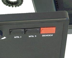
 for gooseneck microphone or headset 5 - Call buttons for Call 1 (\"RUF 1\", 1750")

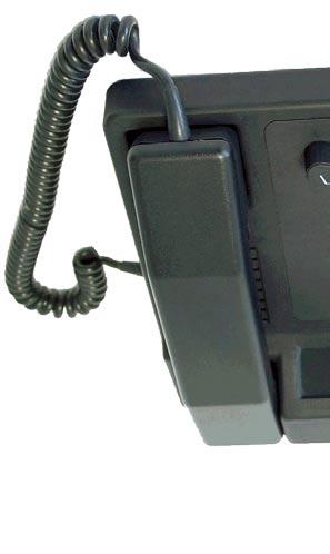
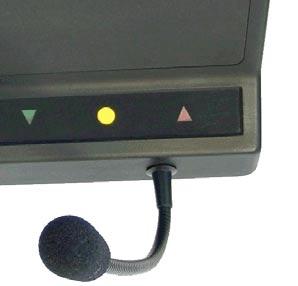
3 Control Elements PTT Display LED 2 - Operation LED is on if working current is applied 3 - Carrier display, squelch 4 - PTT button ("SENDEN", red) for gooseneck microphone or headset 5 - Call buttons for Call 1 ("RUF 1", 1750 Hz) and Call 2 ("RUF 2, 2135 Hz) PTT and tone are activated 6 - Volume control of the loudspeaker 7 - Loudspeaker 8 - PTT button of the handpiece 9 - Handpiece Major BOS 1a is also available without the buttons Call 1 and Call mbos1a( )
 ST2, HS (headset) POWER, 12 VDC, max. 1.5 A, inside: positive pole, outside: GND Pinout S/E (radio circuit) ST1 AF input B 1 AF input A 2 squelch input 3 GND 4 output: +12 V, max.")
4 Rearview of Major BOS 1a Sockets Pinout Major BOS 1a All schemes show the sockets viewed from the back of the Major. ST4, TB (tape, ext. speaker) ST1, S/E (radio circuit) ST3, PTT (e.g. foot switch) ST2, HS (headset) POWER, 12 VDC, max. 1.5 A, inside: positive pole, outside: GND Pinout S/E (radio circuit) ST1 AF input B 1 AF input A 2 squelch input 3 GND 4 output: +12 V, max. 300 ma 5 PTT in/output 6 AF output A 7 AF output B 8 Pinout HS ST2 GND 1 AF microphone 2 AF earpiece 3 GND (for earpiece) 4 GND (for microphone) 5 PTT, active GND 6 All AF in/outputs are equipped with transformers and hence potential-free. PIN 5 (+12V) is for supply of external devices (LIM-AC, FT634C, FT633AC, FT630). Attention: Do not use PIN 5 to supply a radio set. 300 ma output current is not sufficient. Pinout PTT ST3 GND 1 GND (for microphone) 2 AF earpiece 3 GND (for earpiece) 4 AF microphone 5 PTT, active GND 6 Pinout TB (tape) ST4 ext. loudspeaker + 1 ext. loudspeaker GND 2 tape AF output A (mod. +) 3 tape AF output B (mod. -) 4 The AF outputs A-B are equipped with transformers and hence potential-free mbos1a ( )
5 Major BOS 1a - General Remarks The Major BOS 1a is a µc-based control set for radios allowing the adjustment of different levels and parameters. The radio is connected to the squelch input, the PTT output and the AF in/output. For operation 12 V DC supply is necessary. As the AF output is only open during transmission, several Major BOS 1a can be connected in parallel. The PTT output can also be used as an input for muting in order to avoid feedback between control sets placed adjacently to each other. Talking to the Radio There are three different ways to talk to a connected radio: 1. by pressing the red PTT button and using the gooseneck or a headset microphone for voice transmission 2. by using the handpiece and its PTT button 3. by using an external PTT button (e.g. foot switch) for talking via headset or gooseneck microphone In all cases the PTT display LED is activated. Volume Settings The volume of the loudspeaker (also for ext. loudspeaker) is set via the volume control knob. The volume of the handpiece as well as the level of its microphone can be adjusted at the handpiece. The potentiometers are situated near the respective capsules. The microphone levels for the headset and the gooseneck microphone can be set internally. Muting of the Loudspeaker The loudspeaker is always muted automatically during transmission. When the handpiece is taken, the loudspeaker is muted if jumper JMP3b (4-6) is pulled out. The loudspeaker can also be muted by an external PTT output in order to avoid feedback between control sets placed adjacently to each other. The polarity is set by JMP2b (4-6) and has to be the same as for the PTT output JMP2a (1-3). If no muting is desired, JMP2b must be removed. Tone Call Encoder The Major BOS 1a has two single tone encoders, Call 1 (1750 Hz) and Call 2 (2135 Hz). The calls are sent using the respective buttons of the control panel. The tone call is sent as long as the button is pressed mbos1a( )
6 Transmitter Control The transmitter is switched on with one of the PTT or Call buttons as long as it is pressed. The PTT output can switch to GND as well as to 12 V. Via the open collector output several control sets can be connected in parallel. Connecting several Control Sets in Parallel As the NF output is only active during transmission and the NF input can be switched to high-resistance, the connection of several control sets in parallel is possible. Therefor, RJ45 patch sockets can be used (bus wiring or star wiring). By decoding the PTT output (in this case used as an input) it is possible to mute the Major BOS 1a externally in order to avoid feedback between control sets placed adjacently to each other. Headset An external headset with a suitable foot switch can be connected to one of the 6-pin Western sockets. The sockets' pinout differs only in the polarity of the electret microphone's bias voltage in order to provide the two frequently used pin assignments for headsets with 4/6-pin Western plugs. Tape Connection For voice recording a tape recorder can be connected to socket ST4. The output level can be set internally. External Loudspeaker An external loudspeaker can be connected to ST4. The volume is set with the main volume control knob mbos1a ( )
7 Jumper Jumper Pos. Function JMP1a 1-2 input impedance AF input 200 ohm, ST1 pin1-2 JMP1a 2-3 input impedance AF input 200 ohm, ST1 pin1-2 JMP1a open input impedance AF input high-resistance, ST1 pin1-2 JMP1b 4-5 squelch input volt, ST1 pin3 JMP1b 5-6 squelch input GND, ST1 pin3 JMP1b open squelch input not active JMP2a 1-2 PTT output switches to +12 V, ST1 pin6 JMP2a 2-3 PTT output switches to GND, ST1 pin6 JMP2a open PTT output permanently inactive JMP2b 4-5 PTT input to +12 V, ST1 pin6 JMP2b 5-6 PTT input to GND, muting off, ST1 pin6 JMP2b open PTT input inactive, muting permanently off JMP3a 1-2 ext. PTT = headset, int. PTT = gooseneck microphone JMP3a 2-3 ext. PTT = headset with Headset -> int. PTT = headset, without Headset -> int. PTT = gooseneck microphone JMP3a open not used JMP3b 4-5 loudspeaker switched off when handpiece is taken JMP3b 5-6 loudspeaker remains active when handpiece is taken JMP3b open loudspeaker switched off when handpiece is taken JMP4a 1-2 max. volume unlimited (2,0 W) JMP4a 2-3 max. volume limited (1,5 W) JMP4a offen max. volume limited (1,5 W) JMP4b 4-5 min. volume always present JMP4b 5-6 min. volume off JMP4b offen min. volume always present Potentiometer Poti Function/Level P1 AF input sensitivity ST1, pin 1-2 P2 AF output total volume ST1, pin 7-8 P3 sensitivity gooseneck microphone P4 sensitivity headset microphone P5 volume poti front plate P6 NF output level tape ST4, pin mbos1a( )
 Adjustment of the AF input: a) apply the AF-level specified by the radio (e.g.")
 at ST4/pins3+4 (600 Ohm Anschluss) 2) Adjustment of the AF output a) connect the level meter and the radio to the AF output. The desired level (e.g.")
8 POWER Board Layout P6 P2 ST4 ST1 ST3 ST2 P1 ST8 P3 P JMP3a JMP3b JMP1a JMP1b JMP2a JMP2b ST6A ST7A ST5A P5 1 3 JMP4a 4 6 JMP4b ST6B Calibrating the AF levels The AF levels are calibrated correctly ex factory. If a recalibration is necessary please follow the steps below. 1) Adjustment of the AF input: a) apply the AF-level specified by the radio (e.g. 500 mv) at 1000 Hz to the AF input (ST1/pin1+2) b) adjust P1 to approx. 530 mv at ST5A/pin1 or ST2/pin 3 or ST3/pin 3 (without load, vs. GND) c) adjust P6 (Tape) to the desired tape level (norm. 500 mv) at ST4/pins3+4 (600 Ohm Anschluss) 2) Adjustment of the AF output a) connect the level meter and the radio to the AF output. The desired level (e.g. 520 mv at 200 ohm) is the level of the nominal stroke demanded by the radio b) press button for call 1 (1750 Hz) and adjust desired level with P2 c) adjust the desired level of the gooseneck microphone using P3 while talking normally into it d) adjust the desired level of the headset using P4 while talking normally into it e) adjust the desired level of the handset using the poti near the microphone while talking normally into it mbos1a ( )
9 Technische Daten Operating voltage +12V DC -15% +25% Current consumption max ma, typ. 500 ma AF input level (ST1, pin 1-2) nominal adjustment range using poti P1 input impedance AF output level (ST1, pin 7-8) ex factory adjustment range output impedance while transmitting output impedance while receiving 500 mv at 200 ohm mv 200 ohm, 600 ohm oder 10 kohm, ex factory: 200 ohm 500 mv an 200 ohm mv an 200 ohm mv an 600 ohm 200 ohm high-resistance AF output level (earpiece of headset) (ST2+ST3, pin 3-4) Werksseitig eingestellt auf 350 mv an 200 ohm Ausgangsimpedanz ca. 100 ohm AF input level (microphone of headset) (ST2+ST3, pin 1-2) nominal 4 mv adjustment range (using poti P4) 2-11 mv input impedance 700 ohm AF output level of ext. loudspeaker (ST4, pin 1-2) output impedance 4-8 Ohm AF intensity max. 2 watt at 4 ohm Af output level of tape (ST4, pin 3-4) ex factory adjustment range output impedance 500 mv at 600 ohm mv at 600 ohm 600 ohm Weight Dimensions width x depth x height approx g 245 x 220 x 90 mm, without gooseneck microphone mbos1a( )
10 General Safety Information Please read the operating instructions carefully before installation and setup. The relevant regulations must be complied to when working with 230V line voltage, two-wirelines, four-wire-lines and ISDN-lines. It is also very important to comply to the regulations and safety instructions of working with radio installations. Please comply to the following safety rules: - All components may only be mounted and maintained when power is off. - The modules may only be activated if they are built in a housing and are scoop-proof. - Devices which are operated with external voltage - especially mains voltage - may only be opened when they have been disconnected from the voltage source or mains. - All connecting cables of the electronic devices must be checked for damage regularly and must be exchanged if damaged. - Absolutely comply to the regular inspections required by law according to VDE 0701 and 0702 for line-operated devices. - Tools must not be used near or directly at concealed or visible power lines and conductor paths and also not at and in devices using external voltage especially mains voltage - as long as the power supply voltage has not been turned off and all capacitors have been discharged. Electrolytic capacitors can be still charged for a long time after turning off. - When using components, modules, devices or circuits and equipment the threshold values of voltage, current and power consumption specified in the technical data must absolutely be complied to. Exceeding these threshold values (even if only briefly) can lead to significant damage. - The devices, components or circuits described in this manual are only adapted for the specified usage. If you are not sure about the purpose of the product, please ask your specialized dealer. - The installation and setup have to be carried out by professional personnel. Returning of Old Equipment According to German law concerning electronic devices old devices cannot be disposed off as regular waste. Our devices are classified for commercial use only. According to 11 of our general terms of payment and delivery, as of November 2005, the purchasers or users are obliged to return old equipment produced by us free of cost. FunkTronic GmbH will dispose of this old equipment at its own expense according to regulations. Please send old equipment for disposal to: FunkTronic GmbH Breitwiesenstraße Schlüchtern GERMANY >>> Important hint: freight forward deliveries cannot be accepted by us. February 2 nd, 2006 Subject to change, Errors excepted mbos1a ( )
11 Release Notes first English version of Major BOS 1a manual mbos1a( )
Major BOS 2b2. serial number 3799 and later
 Major BOS 2b2 serial number 3799 and later Inhalt Technical Data Page 2 Controls of Major BOS 2b2 3 Major BOS 2b2 4 Programming 4 Connectivity 4 Tastatur 4 Carrier Indication (Squelch) 5 Transmitter Indication
Major BOS 2a2. Serial number 3799 or higher
 Major BOS 2a2 Serial number 3799 or higher Table of Contents Page Technical Data 2 Controls of Major BOS 2a2 3 Major BOS 2a2 4 Programming 4 Connectivity 4 Keypad 4 Carrier Indication (Squelch) 5 Transmitter
Major 4a. Major 5a. English 1.0
 Major 4a Major 5a English 1.0 Inhalt Page Order Information 2 General Features 3 Control Elements Major 4a 4 Control Elements Major 5a 4 Display Elements Major 4a/5a 5 Sockets Pinout Major 4a/5a 6 Rearview
Major BOS V(oIP) Major BOS 4V. Major BOS 1V. Major BOS 8V
 Major BOS 4V. Major BOS 1V. Major BOS 8V") Major BOS V(oIP) Major BOS 1V Major BOS 4V Major BOS 8V Contents Connectivity 3 Major BOS 1V/4V/8V 3 Control and Display Elements 4 Layout - Major BOS 4V 5 Layout - Major BOS 8V 6 Calling Radio Channels
Major BOS V(oIP) Major BOS 1V Major BOS 4V Major BOS 8V Contents Connectivity 3 Major BOS 1V/4V/8V 3 Control and Display Elements 4 Layout - Major BOS 4V 5 Layout - Major BOS 8V 6 Calling Radio Channels
PS 230 DUAL CHANNEL REMOTE SPEAKER STATION. User Manual. January 2017 V1.0
 PS 230 DUAL CHANNEL REMOTE SPEAKER STATION User Manual January 2017 V1.0 Table of contents 1.0 GENERAL DESCRIPTION... 3 2.0 INSTALLATION... 4 3.0 FRONTPANEL CONTROLS & CONNECTORS... 4 4.0 SIDE PANEL CONNECTORS...
Demonstration Case BENNING DB 1
 Operating manual Demonstration Case BENNING DB 1 part no. 044132 Table of contents 1 Introduction...3 2 Safety instructions...4 3 Applicable regulations...5 4 Device description...5 4.1 Measuring / testing...
GREISINGER electronic GmbH. D Regenstauf, Hans-Sachs-Straße 26. T-Logg 120 W -... T-Logg 120 K -...
 E39.0.1X.6C-01 Data logger for standard signals as of version 1.0 Operating Instruction T-Logg 120... T-Logg 120 W -... T-Logg 120 K -... GREISINGER electronic GmbH D - 93128 Regenstauf, Hans-Sachs-Straße
PS 630 SIX CHANNEL REMOTE SPEAKER STATION. User Manual. January 2017 V1.0
 PS 630 SIX CHANNEL REMOTE SPEAKER STATION User Manual January 2017 V1.0 Table of contents 1.0 GENERAL DESCRIPTION... 3 2.0 INSTALLATION... 4 3.0 FRONTPANEL CONTROLS & CONNECTORS... 4 4.0 REAR PANEL CONNECTORS...
PS 430 FOUR CHANNEL REMOTE SPEAKER STATION. User Manual. January 2017 V1.0
 PS 430 FOUR CHANNEL REMOTE SPEAKER STATION User Manual January 2017 V1.0 Table of contents 1.0 GENERAL DESCRIPTION... 3 2.0 INSTALLATION... 4 3.0 FRONTPANEL CONTROLS & CONNECTORS... 4 4.0 SIDE PANEL CONNECTORS...
BS 15 BASIC SERIES USER MANUAL FOR THE SINGLE CHANNEL BELTPACK CONTENTS
 BASIC SERIES USER MANUAL FOR THE BS 15 SINGLE CHANNEL BELTPACK CONTENTS 1.0 GENERAL DESCRIPTION... 3 2.0 UNPACKING... 3 3.0 INSTALLATION... 3 4.0 FRONT PANEL CONTROLS... 4 5.0 REAR PANEL CONNECTORS...
Orbis MU 21. Digital Delegate Microphone Unit with Loudspeaker Order #
 Digital Delegate Microphone Unit with Loudspeaker Order # 725.706 Supplied without gooseneck microphone FEATURES Coated plastic housing with metal bottom plate Inserts made of optically hardened acrylic
PS 150 SINGLE CHANNEL TELEPHONE INTERFACE. USER MANUAL August 2016
 PS 150 SINGLE CHANNEL TELEPHONE INTERFACE USER MANUAL August 2016 This product is designed and manufactured by: ASL Intercom B.V. Zonnebaan 42 3542 EG Utrecht The Netherlands Phone: +31 (0)30 2411901 Fax:
INSTALLATION MANUAL. LC 200 Electronic Overload Guard. Software versione PW0501 R 0.3
 INSTALLATION MANUAL LC 200 Electronic Overload Guard Software versione PW0501 R 0.3 CONTENTS MAIN FEATURES LC 200 TECHNICAL FEATURES Page 2 SYMBOLS Page 3 WARNINGS Page 3 IDENTIFICATION DATA PLATE Page
Rhino Buffer Module PSM24-BFM600S. Operating Instructions
 Rhino Buffer Module PSM24-BFM600S Operating Instructions RHINO BUFFER MODULE PSM24-BFM600S Description The PSM24-BFM600S Buffer Module will hold the output voltage of a 24 VDC power supply after brownouts
TELIKOU Intercom System
 TELIKOU Intercom System MS-800 Main Station Instruction Manual 2006 TELIKOU Systems All Rights Reserved While TELIKOU makes every attempt to maintain the accuracy of the information contained in its product
OPT2011. High-performance distance sensor. Operating Instructions
 OPT2011 High-performance distance sensor Operating Instructions Status: 15/07/2013 2 Table of Contents 1. Use for Intended Purpose 4 2. Safety Precautions 4 2.1. Safety Precautions 4 2.2. Laser/LED warning
Operating Manual UMB ISO Converter ISOCON Order Number: 8160.UISO
 Order Number: 8160.UISO Status: V3; 17.09.2010c G. Lufft Mess- und Regeltechnik GmbH, Fellbach, Germany 1 TABLE OF CONTENTS PLEASE READ BEFORE USE... 3 DESCRIPTION... 5 UMB ISO CONVERTER ISOCON... 6 CONFIGURATION...
AMP20. User Manual.
 AMP20 User Manual www.audac.eu 2 Index Introduction 5 Precautions 6 Safety requirements 6 Caution servicing 7 EC Declaration of Conformity 7 Waste of Electrical and Electronic Equipment (WEEE) 7 Chapter
PHOENIX CONTACT - 07/2006
 Buffer module with maintenance-free capacitor-based power storage device INTERFACE Data sheet 102035_03_en PHOENIX CONTACT - 07/2006 Description Short-term mains interruptions are bridged by QUINT BUFFER,
PolluTherm. calculator hous. 2 from hous. 1 until X X X X X* X* M-Bus- M-Bus and 2 2PM pulse inputs X X X X
 1. Use of the option modules There are two different housings with which these same plug-in units can be used namely: Calculator housing 1 (PolluTherm, PolluStat E and PolluFlow 2010) indicated by a lid
DM-918 OPERATIONS MANUAL AUTORANGING MULTIMETER
 DM-918 OPERATIONS MANUAL AUTORANGING MULTIMETER SAFETY INFORMATION The following safety information must be observed to ensure maximum personal safety during the operation of this meter: This meter is
STAGE INTERCOM KIT 1.1 SPECIFICATION. General: The lower section is a small power amplifier designed to drive headphones or a small 8ohm speaker.
 STAGE INTERCOM KIT Version 2.1.1 - March 2018 - EduTek Ltd 1.0 DESCRIPTION This intercom module comprises of two separate circuits sharing the same supply. The upper section is a pre-amplifier designed
Product Information. DCM Standard indoor stations TK IS A 514 A.. TK IS A 514 AD.. (Design)
") Product Information DCM Standard indoor stations TK IS A 514 A.. TK IS A 514 AD.. (Design) ALBRECHT JUNG GMBH & CO. KG Volmestraße 1 58579 Schalksmühle Phone +49.2355.806-0 Fax +49.2355.806-189 E-Mail:
Product Information DCM Standard indoor stations TK IS A 514 A.. TK IS A 514 AD.. (Design) ALBRECHT JUNG GMBH & CO. KG Volmestraße 1 58579 Schalksmühle Phone +49.2355.806-0 Fax +49.2355.806-189 E-Mail:
HERCULES-5000 INSTRUCTION MANUAL
 IndustrieAlpine Allee 1 D - 94513 Schönberg Tel.:+49 (0) 85 54/9609-0 Fax:+49 (0) 85 54/96 09 20 Mail: sales@tetelectronics.de INSTRUCTION MANUAL HERCULES-5000 High-performance power supplies Page 1 von
Stereo - Amplifier. User s Manual
 Stereo - Amplifier User s Manual User's Manual Audionet is proud to welcome you in the world of German high-end! Your Audionet SAM (= Stereo AMplifier) is designed for natural and audiophile music reproduction
Orbis MU 41. Digital Flush Mount Delegate Microphone Unit Order #
 Digital Flush Mount Delegate Microphone Unit Order # 725.722 Optional CA OL loudspeaker module, not included Table installation supplied without gooseneck microphone FEATURES High-quality flush mounting
OPERATING MANUAL. DMX Booster/Splitter 3405A-FGR DMX Booster/Splitter 3410A-FGR
 Issue 12/10 OPERATING MANUAL DMX Booster/Splitter 3405A-FGR DMX Booster/Splitter 3410A-FGR Jumper Setting Instructions (C) SOUNDLIGHT 1996-2012 * ALL RIGHTS RESERVED * NO PART OF THIS MANUAL MAY BE REPRODUCED,
Strain Gage Measuring Amplifier GSV-1
 Strain Gage Measuring Amplifier GSV-1 Tel 03302 559 282, Fax: 03302 559 141, info@me-systeme.de, www.me-systeme.de 1 Strain Gage Measuring Amplifier GSV-1 Description...3 Models...4 Technical Data...5
INTEGRUS. LBB 3222/04 6-Channel Interpreter Desk with Loudspeaker. LBB 3422/20 Integrus Audio Input and Interpreters Module
 INTEGRUS en Installation and User Instructions Integrus Language Distribution System LBB 3222/04 6-Channel Interpreter Desk with Loudspeaker LBB 3422/20 Integrus Audio Input and Interpreters Module INTEGRUS
INTEGRUS BOSCH DIGITAL INFRA-RED LANGUAGE DISTRIBUTION SYSTEM. Installation and Operating Manual
 INTEGRUS DIGITAL INFRA-RED LANGUAGE DISTRIBUTION SYSTEM Installation and Operating Manual LBB 3222/04 6-Channel Interpreter Desk with Loudspeaker LBB 3422/10 Symmetrical Audio Input and Interpreters Module
PMX-CSK Promatrix Call Station Kit
 Engineering Data Sheet PMX-CSK Promatrix Call Station Kit The PMX-CSK call station kit is a call station printed circuit board (PCB) for the PROMATRIX system. The circuit board allows an application-specific
Command Talk-Back & Public Address System ETB-5 / ETB-10 / ETB-10A / ETB-100 / ETB-100A
 Command Talk-Back & Public Address System ETB-5 / ETB-10 / ETB-10A / ETB-100 / ETB-100A TECHNICAL MANUAL About this Document Document Scope This document is intended for qualified technicians who will
MODEL NC105 DIGITAL CODED SQUELCH ENCODER/DECODER INSTRUCTION MANUAL
 15385 Carrie Drive Grass Valley, CA 95959 Office: (530) 477-8400 Tech. Support: (530) 477-8402 FAX: (530) 477-8403 Sales: (800) 874-8663 Email: tech@norcommcorp.com Web: www.norcommcorp.com MODEL NC105
SPECIAL INSTRUCTIONS FOR CAPACITORS COMPACT GENERATORS
 SPECIAL INSTRUCTIONS FOR CAPACITORS COMPACT GENERATORS (WITH CAPACITOR CHARGER BOARD A3517-02) The process depends on Generator and System configuration. This document applies to installation of Capacitors
Transducers for Pt-100/1000, Resistors
 Transducers for Pt-100/1000, Resistors Microprocessor-based technology General Description Isolating transducers with digital programming of ranges, for DIN-rails or for printed circuit boards. Modules
Model A Mini AC/DC Clamp Meter. User's Guide
 Model 380950 80A Mini AC/DC Clamp Meter User's Guide Introduction Congratulations on your purchase of the Extech 80A Mini AC/DC Clamp Meter. The Model 380950 measures AC/DC Current, AC/DC Voltage, Resistance,
200B-G Tone Probe. 200EP-G Tone Probe INSTRUCTION MANUAL. with Adjustable Volume
 INSTRUCTION MANUAL English...1 Français...9 Español...17 Deutsch...25 Italiano...33 Português do Brasil...41 200B-G Tone Probe with Adjustable Volume 200EP-G Tone Probe with Adjustable Volume, Visual Signal
Connecting the THP-700RTS to a Telephone and Radio Console - Summary. DynaMetric. Made in USA THP-700RTS
 Connecting the to a Telephone and Radio Console - Summary RECORDER 700RTS 700RTS PHONE PIN HEADSET PIN JACK PIN PLUG* PIN JACK 1 1 MIC 1 1 Make same 2 2 EAR 2 2 as Phone 3 3 EAR 3 3 Jack 4 4 MIC 4 4 PIN
GREISINGER electronic GmbH. D Regenstauf, Hans-Sachs-Straße 26. T-Logg 100. T-Logg 100 E
 E39.0.0X.6C-03 Data logger for temperature as of version V1.3 Operating Manual T-Logg 100 T-Logg 100 T-Logg 100 E GREISINGER electronic GmbH D - 93128 Regenstauf, Hans-Sachs-Straße 26 +49 (0) 9402 / 9383-0
GREISINGER electronic GmbH D Regenstauf, Hans-Sachs-Straße 26
 E39.0.31.6C-02 Data logger for humidity temperature as of version V1.0 Operating Manual T-Logg 160 GREISINGER electronic GmbH D - 93128 Regenstauf, Hans-Sachs-Straße 26 +49 (0) 9402 / 9383-0 +49 (0) 9402
Isolated Process Current Input with Loop Power 7B35
 Isolated Process Current Input with Loop Power 7B35 FEATURES Single-channel signal conditioning current input module that interfaces with two-wire transmitters. Module provides a precision output of either
Advanced Visual Solutions Ltd
 Advanced Visual Solutions Ltd Unit 2, Eastman Way Hemel Hempstead, Hertfordshire HP2 7DU Telephone : ( 01442 ) 252280 Fax : ( 01442 ) 244578 Email : visionservices@btclick.com : Website : www.avsl.com
Isolated, Voltage or Current Input 7B30 FEATURES APPLICATIONS PRODUCT OVERVIEW FUNCTIONAL BLOCK DIAGRAM
 Isolated, Voltage or Current Input 7B30 FEATURES Interfaces, amplifies and filters unipolar and bipolar millivolt and voltage inputs. Provides a protected precision output of either +1 V to +5 V or 0 V
Isolated Process Current Input 7B32 FEATURES APPLICATIONS PRODUCT OVERVIEW FUNCTIONAL BLOCK DIAGRAM
 Isolated Process Current Input 7B32 FEATURES Interfaces, amplifies and filters a process-current input. Module provides a precision output of either +1 V to +5 V or 0 V to +10 V, linear with temperature.
BB-303 Manual Baseboard for TMCM-303
 BB-303 Manual Baseboard for TMCM-303 Trinamic Motion Control GmbH & Co. KG Sternstraße 67 D 20357 Hamburg, Germany http://www.trinamic.com BB-303 Manual (V1.04 / Jul 9th, 2007) 2 Contents 1 Features...
VersaMax IP I/O Module
 Module accepts four digital input signals and provides four digital outputs. It connects to a local bus that is interfaced to a Profibus-DP / PROFINET network by a Profibus Interface Unit (IC677PBI001)
DIGITAL AUDIO DELAY MODULE (DADM) INSTRUCTIONS
 INSTRUCTIONS") DIGITAL AUDIO DELAY MODULE (DADM) INSTRUCTIONS Thank you for purchasing the ICS Digital Audio Delay Module! PRODUCT DESCRIPTION The Digital Audio Delay Module (DADM) is an enhanced replacement for the
DIGITAL AUDIO DELAY MODULE (DADM) INSTRUCTIONS Thank you for purchasing the ICS Digital Audio Delay Module! PRODUCT DESCRIPTION The Digital Audio Delay Module (DADM) is an enhanced replacement for the
MEASURING AND TESTING INSTRUMENTS
 MEASURING AND TESTING INSTRUMENTS Whether measuring temperature, current or voltage testing the right measuring tool can facilitate the everyday work. If one wants to perform several measuring tasks at
MINI-PS AC/10-15DC/8
 Primary-Switched Power Supply, Narrow Design Data Sheet 08/2004 MINI POWER provides: An extra narrow design, with widths of 22.5 mm, 45 mm, and 67.5 mm (0.886, 1.772, and 2.657 in.) Global use due to a
This data sheet is only valid in association with the IL SYS INST UM E user manual.
 Inline analog input terminal, 4 inputs for connecting voltage signals Data sheet 8081_en_01_C01 PHOENIX CONTACT 2015-04-14 1 Description The terminal is designed for use within an Inline station. It is
Model User Manual Revision E 04/29/99. OEM Gaging System. Part Number R01
 04/29/99 Model 3800 OEM Gaging System User Manual Revision E Part Number 028585-R01 Information in this document is subject to change without notice. No part of this document may be reproduced or transmitted
WR-5e Remote Control
 1. Introduction WR-5e Remote Control The WR-5e is a microprocessor based serial data remote control unit for Ashly NE or NX products. Compatible products currently include Pema amplifiers, ne8800 and ne4800
User Manual. 400Amp AC Clamp Meter + NCV. Model MA430. Additional User Manual Translations available at
 User Manual 400Amp AC Clamp Meter + NCV Model MA430 Additional User Manual Translations available at www.extech.com Introduction Congratulations on your purchase of this Extech MA430 Clamp Meter. This
PSM-ME-RS232/TTY-P Interface converter for RS-232 to TTY transmission systems
 Interface converter for RS- to transmission systems. Short Description The rail-mountable and compact interface converters have been designed especially for industrial use in the switch cabinet or switch
Isolated Voltage Input 7B31 FEATURES APPLICATIONS PRODUCT OVERVIEW FUNCTIONAL BLOCK DIAGRAM
 Isolated Voltage Input 7B31 FEATURES Interfaces, amplifies, and filters unipolar and bipolar voltage inputs. Module provides a precision output of either +1 V to +5 V or 0 V to +10 V, linear with temperature.
C S Technology Ltd. cstech.co.uk. DTMF display 32 kit with 2 line x 16 LCD display
 C S Technology Ltd cstech.co.uk DTMF display 32 kit with 2 line x 16 LCD display Our DTMF display can display up to 32 characters (16 per line). The display can be cleared by a button (not supplied) or
DIGITAL DISPLAY. for Industry Applications. Series WAY-SSI. Key-Features:
 DIGITAL DISPLAY for Industry Applications Series WAY-SSI Key-Features: Content: Technical Data.2 Technical Drawing...2 Electrical Connection...3 Description...4 Order Code & Accessories...6 - WAY-SSI-S:
WALL MOUNTED PANEL. SECTION 2G (Rev.E) SECTION CONTENTS. Download from Technical Manuals area. sec.2g SMYLE WALL-MOUNTED PANEL 2
 SECTION CONTENTS. Download from Technical Manuals area. sec.2g SMYLE WALL-MOUNTED PANEL 2") SECTION G (Rev.E) 8 WALL MOUNTED PANEL 8 Download from www.urmet.com Technical Manuals area. SMYLE WALL-MOUNTED PANEL SECTION CONTENTS SPECIAL MODULES...8 TECHNICAL FEATURES... DOOR UNITS... Door phone
SECTION G (Rev.E) 8 WALL MOUNTED PANEL 8 Download from www.urmet.com Technical Manuals area. SMYLE WALL-MOUNTED PANEL SECTION CONTENTS SPECIAL MODULES...8 TECHNICAL FEATURES... DOOR UNITS... Door phone
English. Operating manual. Universal transmitter UT125. Save for later reference. Companies / brands of GHM
 English Operating manual Universal transmitter UT125 Companies / brands of GHM www.ghm-messtechnik.de Save for later reference. Table of contents page 1. Intended use (areas of application)... 3 1.1 Safety
ADC7520 SERIES. 1600W Battery Chargers and Power Supplies
 ADC7520 SERIES 1600W Battery Chargers and Power Supplies Wide output adjustment range 0 72VDC Analog control by external 0-5VDC voltage Temp.comp charging, sense as on option Power fail relay alarm Master-Slave
Voice Keyer Kit by DH8BQA (BX-184)
") Voice Keyer Kit by DH8BQA (BX-184) 2011 5 24 1 Quick assembly guide Most amateur radios do not have an internal voice memory for transmitting. If you want to use such a convenient feature you can build
Voice Keyer Kit by DH8BQA (BX-184) 2011 5 24 1 Quick assembly guide Most amateur radios do not have an internal voice memory for transmitting. If you want to use such a convenient feature you can build
ABB Drives. User s Manual Pulse Encoder Interface Module MTAC-01
 ABB Drives User s Manual Pulse Encoder Interface Module MTAC-01 Pulse Encoder Interface Module MTAC-01 User s Manual 3AFE68591091 REV B EN EFFECTIVE: 04.04.2006 2006 ABB Oy. All Rights Reserved. 5 Safety
INSTALLATION INSTRUCTIONS
 INSTALLATION INSTRUCTIONS MicroComm DXI. Intent & Scope This document describes the installation procedure for the IMS-30 Intercom Master Station and the MAI-420 or MAI-20 Master Audio Interface. The earliest
Strain Gage Measuring Amplifier GSV-3
 Strain Gage Measuring Amplifier GS-3 Tel 03302 559 282, Fax: 03302 559 141, info@me-systeme.de, www.me-systeme.de 1 Strain Gage Measuring Amplifier GS-3 Description...4 Models...5 Measurement Resolution...5
RXM39.1. PL-Link IO Block. Desigo TRA. Use with PXC3 series room automation station
 s 3 836 3836P01 Desigo TRA PL-Link IO Block Use with PXC3 series room automation station RXM39.1 The PL-Link IO Block contains the inputs and outputs controlled by a room automation station via PL-Link.
APM. User manual & Installation guide. Digital paging microphone.
 APM User manual & Installation guide Digital paging microphone www.audac.eu 2 Index 3 Introduction 5 Precautions 6 Chapter 1: Overview of APM1xx 9 Indicator LED functions 11 Button functions 12 Chapter
OPERATING INSTRUCTION
 OPERATING INSTRUCTION AUTORANGING MULTIMETER MAX Ω F C 10A MAX every 15 min. COM V SAFETY INFORMATION The following safety information must be observed to insure maximum personal safety during the operation
TinyTrak4 v7 Hardware Manual
 Overview TinyTrak4 v7 Hardware Manual Version 7.2 July 23, 2017 The TinyTrak4 (TT4) is a radio interface capable of transmitting and receiving position and other digital information over a two-way FM radio.
INSTALLATION INSTRUCTIONS
 BY BY INSTALLATION INSTRUCTIONS KP95-0 KEYPANEL VERSION 8.2 WITH EKPD-95 EXPANSION PANEL ADAM, ADAM CS, AND ZEUS INTERCOM SYSTEMS Talk Off (Talk) Matrix Intercom System Talk Clear Off Call Answer Incoming
Telex Operating Instructions
 Telex Operating Instructions Echelon ANR TM 150 Headset Figure 1 Note: See page 7 for available replacement parts. General Description The Echelon ANR 150 is a medium-weight aircraft communications headset.
Isolated, Voltage or Current Input 7B41 FEATURES APPLICATIONS PRODUCT OVERVIEW FUNCTIONAL BLOCK DIAGRAM
 Isolated, Voltage or Current Input 7B41 FEATURES Interfaces, amplifies and filters unipolar and bipolar voltage inputs. Module provides a precision output of either +1 V to +5 V or 0 V to +10 V. All 7B41
User s Manual Pulse Encoder Interface Module OTAC-01
 Drive IT Low Voltage AC Drives User s Manual Pulse Encoder Interface Module OTAC-01 2 Safety WARNING! All electrical installation and maintenance work on the drive should be carried out by qualified electricians
Operation Manual Locator Wöhler L 200
 Operation Manual Locator Wöhler L 200 Best.-Nr. 22849 2014-12-18. Contents Contents 1 General Information... 3 1.1 Operation Manual Information... 3 1.2 Notes in this manual... 3 1.3 Proper use... 3 1.4
Autoranging True RMS Multimeter User Manual
 Autoranging True RMS Multimeter User Manual Please read this manual before switching the unit on. Important safety information inside. Contents Page 1. Safety Information... 4 2. Safety Symbols... 5 3.
Zartek. CDP-808 Two Button Wireless Intercom Installers Manual
 Zartek CDP-808 Two Button Wireless Intercom Installers Manual ZA-614 Two Button Gate station including power supply, relay board and external antenna ZA-613 Handsets with charger ZA-613-E Handsets with
The Digital Matrix Platform for Intercom, Audio & IP-Routing. Installation Guide. Artist M Installation Guide Version
 The Digital Matrix Platform for Intercom, Audio & IP-Routing Installation Guide Artist M Installation Guide Version 3.03 12.09.05 1 General Thank you for choosing the Artist M digital matrix platform.
INSTALLATION INSTRUCTIONS
 INSTALLATION INSTRUCTIONS MicroComm DXI MAI-425 Master Audio Interface. Intent & Scope This document describes the installation procedure for the MAI-425 Master Audio Interface. The earliest version of
LVX Control Unit. Features:
 Date 2013-02-28 Control Unit Features: Most parameters can be defined as required for your interfaces. You decide which information is output and how. Fast cycle times, just a few µs/beam. Maximum beam-count
USER MANUAL MBAR EX By JETI model s.r.o
 USER MANUAL MBAR EX By JETI model s.r.o. 14. 11. 2014 CONTENTS 1. INTRODUCTION...3 2. MAIN FEATURES...3 3. PLACEMENT OF MBAR EX SENSOR...3 4. CONNECTING THE MBAR EX SENSOR...4 5. SETTING VIA JETIBOX...5
Installation and Maintenance
 Installation and Maintenance TT1000 TT3000 TT4000 Version 1.3 e-data GmbH 01.2009 Version 1.3 1-1 1 Usage 1-3 1.1 Protection Class and Protection Type... 1-3 1.2 Safety Measures... 1-3 1.3 Before Commissioning...
Manual Main PCB Small-MIDI 4
 Index PARTLIST MAIN PCB... 2 INTRODUCTION... 3 GENERAL... 3 THE CIRCUIT... 3 ASSEMBLY KIT... 4 ASSEMBLY OF THE PCB... 4 An important tip...... 4 ASSEMBLY... 4 THE CONNECTORS... 4 Power supply J1... 4 IDC
Type Version Ordering Code Package PEB 2025-N V 1.5 Q67100-H6300 P-LCC-28-R (SMD) PEB 2025-P V 1.5 Q67100-H6241 P-DIP-22
 PEB 2025-P V 1.5 Q67100-H6241 P-DIP-22") ISDN Exchange Power Controller (IEPC) PEB 2025 CMOS IC Features Supplies power to up to four transmission lines CCITT recommendations compatible for power feed at the S interface Each line is individually
ISDN Exchange Power Controller (IEPC) PEB 2025 CMOS IC Features Supplies power to up to four transmission lines CCITT recommendations compatible for power feed at the S interface Each line is individually
Electronic SD1, AS 8, ASR 14, ASR 20
 Electronic SD1, AS 8, ASR 14, ASR 20 2 Electronic SD1, AS 8, ASR 14, ASR 20 Contents Page List of contents..................................................... 3 Function and characteristics.........................
Product and functional description
 Product and functional description The RS 525/23 Universal Dimmer is a KNX device with one dimmer output. The device is installed in an AP 118 Control Module Box or an AP 641 Room Control Box. The bus
BASIC PA AMPLIFIER A-1031 A-1061 A-1121 OPERATING INSTRUCTIONS TABLE OF CONTENTS
 OPERATING INSTRUCTIONS BASIC PA AMPLIFIER A-1031 A-1061 A-1121 Please follow the instructions in this manual to obtain the optimum results from this unit. We also recommend that you keep this manual handy
GENERAL DESCRIPTION SPECIFICATIONS. output Impedance: Phones: 60 ohms (Designed for use with ohm phones.)
") GENERAL DESCRIPTION The IC-S is a single-channel speaker station designed for use with an external microphone. There are four versions of the IC-S; all identified by the same model name, but distinguished
GENERAL DESCRIPTION The IC-S is a single-channel speaker station designed for use with an external microphone. There are four versions of the IC-S; all identified by the same model name, but distinguished
TELIKOU Intercom System FT-800 (7+1) Channel Main Station Instruction Manual
 Channel Main Station Instruction Manual") TELIKOU Intercom System FT-800 (7+1) Channel Main Station Instruction Manual TELIKOU Systems All Rights Reserved I. Introduction Thank you for choosing TELIKOU intercom products. Our BK-100 belt packs
TELIKOU Intercom System FT-800 (7+1) Channel Main Station Instruction Manual TELIKOU Systems All Rights Reserved I. Introduction Thank you for choosing TELIKOU intercom products. Our BK-100 belt packs
Manual. Panelmeter EX20xx, EX30xx
 www.bue.de Manual Panelmeter EX20xx, EX30xx EN Attention! Read this first! Read through the Instructions manual carefully. The warranty becomes null and void if damage or injury results from non-compliance
Blue Point Engineering
 Blue Point Engineering Board - Pro Module (E) Instruction Pointing the Way to Solutions! Controller I Version 2.1 The Board Pro E Module provides the following features: Up to 4 minutes recording time
IC-I AND IC-I F GENERAL DESCRIPTION SPECIFICATIONS. Output Impedance: Phones: 60 ohms (Unit is designed for use with ohm phones.
 IC-I AND IC-I F GENERAL DESCRIPTION The IC-1 and IC-1 F are single-channel, singleline intercom stations designed for use with dynamic headsets. The IC-1 is a compact, lightweight unit which may be worn
Accessories and options
 Novigo Accessories and options PCA2001-A1, PCA2002-A1, PCA2004-A1, PCA2005-A1, PCA2007-A1, PCA2008-A1, PCA2011-A1, PCA2012-A1, PCA2013-A1, PCIO2001-A1, PCO2001-A1, PNA2007-A1 Accessories and optional components
CAEN. Electronic Instrumentation. NIM slot 5U CERN Compliant NIM Crate. Rev July Tools for Discovery
 Tools for Discovery n Es NIM8303 12 slot 5U CERN Compliant NIM Crate Rev. 6-13 July 2016 Purpose of this Manual This document is the NIM8303 12 slot 5U CERN Compliant NIM Crate User's Manual; it contains
MKE. User's Guide (Version 2) Universal Midi Keyboard Electronics
 Universal Midi Keyboard Electronics") MKE Universal Midi Keyboard Electronics User's Guide (Version 2) 2012 by Doepfer Musikelektronik GmbH Geigerstr. 13 82166 Graefelfing Germany Phone: #49 89 89809510 Fax: #49 89 89809511 Web Site: www.doepfer.de
MKE Universal Midi Keyboard Electronics User's Guide (Version 2) 2012 by Doepfer Musikelektronik GmbH Geigerstr. 13 82166 Graefelfing Germany Phone: #49 89 89809510 Fax: #49 89 89809511 Web Site: www.doepfer.de
L-LAS Series L-LAS-LT-55. Design. L-LAS Series Laser Line Sensors. Product name: L-LAS-LT-55 (incl. Windows - software L-LAS-LT-Scope)
") L-LAS Series - Visible laser spot (red), class 2 laser product - Reference distance 55 mm - Measuring range typ. 10 mm, resolution typ. 0,01 mm - Integrated interference filter / red light filter - CCD
L-LAS Series - Visible laser spot (red), class 2 laser product - Reference distance 55 mm - Measuring range typ. 10 mm, resolution typ. 0,01 mm - Integrated interference filter / red light filter - CCD
Isolated, Process Current Output 7B39 FEATURES APPLICATIONS PRODUCT OVERVIEW FUNCTIONAL BLOCK DIAGRAM
 Isolated, Process Current Output 7B39 FEATURES Interfaces, isolates and filters a 0 V to + 10 V or +1 V to +5 V input signal. Provides an isolated process current output of 0 ma to 20 ma or 4 ma to 20
Rhino Redundancy Module PSM24-REM360S. Operating Instructions
 Rhino Redundancy Module PSM4-REM360S Operating Instructions RHINO REDUNDANCY MODULE PSM4-REM360S Description With this module and two power supplies of the PSM series (78, 90, 56, 80 and 360 watt models),
Position indicator. Manual
 Position indicator Manual Manufacturer NEW LIFT Steuerungsbau GmbH Lochhamer Schlag 8 82166 Graefelfing Tel Fax Mail +49 89 898 66 0 +49 89 898 66 300 info@newlift.de www.newlift.de Service line Tel +49
Troubleshooting Guide for Firecom Intercoms
 A) I have a problem with Interior Communications - Headset to Headset I cannot communicate between headsets and I cannot hear myself in my own headset. I cannot communicate between headsets but I do hear
Data Sheet 1SD210F2-5SNA0750G Single-Channel SCALE Plug-and-Play IGBT Driver
 Data Sheet 1SD210F2-5SNA0750G650300 Single-Channel SCALE Plug-and-Play IGBT Driver Ultra compact, high-performance driver for 2-level, 3-level and multilevel converters Abstract The SCALE plug-and-play
Data Sheet 1SD536F2-MG1200FXF1US53 Single-Channel SCALE Plug-and-Play IGBT Driver
 Data Sheet 1SD536F2-MG1200FXF1US53 Single-Channel SCALE Plug-and-Play IGBT Driver Ultra-compact, high-performance driver for 2-level, 3-level and multilevel converters Abstract The SCALE plug-and-play