Change Log by Leadshine Technology, All Rights Reserved
|
|
|
- Camilla Richardson
- 6 years ago
- Views:
Transcription
1 Hardware Installation Manual for EM Series Stepper Drives NTS-HWMN-EM-R
2 ii Leadshine reserves the right to make changes without further notice to any products herein to improve reliability, function or design. Leadshine does not assume any liability arising out of the application or use of any product or circuit described herein; neither does it convey any license under its patent rights of others. Leadshine s general policy does not recommend the use of its products in life support or aircraft applications wherein a failure or malfunction of the product may directly threaten life or injury. According to Leadshine s terms and conditions of sales, the user of Leadshine s products in life support or aircraft applications assumes all risks of such use and indemnifies Leadshine against all damages by Leadshine Technology, All Rights Reserved Change Log Revision Date Changes Version Original Create MN-EM-R Correction by NTS NTS-MN-EM-R NTS-
3 iii Safety Items! Notice Read this manual carefully before trying to install the stepper drive into your system. The person setup the stepper drive should have a better understanding on electronics and mechanics. Contact Leadshine technical guys when have questions on this document.! Caution Make sure the power supply voltage dose not exceed the drive s input range. Double check the connections and make sure the power lead polarity is correct.! Warning Do not set high current to small stepper motor. It is possible that the motor will be damaged.! Caution Disconnect the motor from the load if you are not sure the move direction. Adjust the axis in the middle before trying to run the motor.! Warning Never disconnect the motor lead when the power source is energized. NTS-
4 NTS- iv
5 v Table of Contents 1. Family Overview... 1 Introduction... 1.Product Covered phase EM Stepper Drives phase EM Stepper Drives... Fehler! Textmarke nicht definiert. Mechanical Specifications... 2 Elimination of Heat Connectors and Pin Assignment Control Signal Requirement... 4 Signal Mode and Sequence Chart Connecting Control Signal... 5 NPN Signal Connections... 5 PNP Signal Connections... 5 Differential Signal Connections Connecting the Motor phase, 4-lead Motors Connections phase, 6-lead Motors Connections... 6 Half Coil Configurations... 6 Full Coil Configurations phase, 8-lead Motors Connections... 7 Series Connections... 7 Parallel Connections phase Motors Connections... Fehler! Textmarke nicht definiert. Matching Stepper Motors Power Supply Selection... 8 Regulated or Unregulated Power Supply... 8 Multiple Drives... 8 Selecting Supply Voltage... 8 Recommended Supply Voltage Typical Connections Wiring Notes Configuring the Drive Introduction Configuration Procedure Selecting motor Auto Configuration Microstep Resolution Selection Current Settings Dynamic current setting Idle current setting NTS-
6 vi 11. Protection Functions Over-current Protection Over-voltage Protection Sensorless Stall Detection Protection Indications Frequently Asked Questions Problem Symptoms and Possible Causes Appendix Speed Torque Curves for Pre-Matching Leadshine Motors Twelve Month Limited Warranty Exclusions Obtaining Warranty Service Warranty Limitations Shipping Failed Product NTS-
7 1. Family Overview Introduction By implementing the latest motion control technologies, Leadshine's EM series DSP-based stepper drives deliver excellent performance not available before. Unique features of sensorless stall detection, extra smoothness and excellent high speed performance make EM stepper drives deliver servo-like performance at the cost of stepper drives. They are capable of delivering high performance without damages to your machines or the materials. Leadshine EM series stepper drives are able to drive 2-phase stepper motors from NEMA8 to NEMA42..Product Covered The DM series stepper drives can be cataloged as follows: 2-phase EM stepper drives include EM402, EM503, EM705, EM806, EM806AC This manual describes how to install and configure the above stepper drives. 2-phase EM Stepper Drives Part Number Input Voltage Typical Supply Voltage Output Current Pulse Frequency EM402 DC (20-40)V DC 24V RMS ( )A 50K EM503 DC (20-50)V DC 36V RMS ( )A 200K EM705 DC (20-70)V DC 48V RMS ( )A 200K EM806 DC (24-80)V DC 68V RMS ( )A 200K 1
8 Mechanical Specifications EM402 EM503 EM705 EM806 2


9 Elimination of Heat Drive s reliable working temperature(heat sink) should be <70 (158 ), and motor working temperature(surface) should be <80 (176 ); It is recommended to use automatic idle-current mode, namely current automatically reduce to 60% when motor stops, so as to reduce driver heating and motor heating; It is recommended to mount the driver vertically to maximize heat sink area. Use forced cooling method to cool the system if necessary. 3. Connectors and Pin Assignment The EM stepper drives have two connectors, connector for control signals connections and connector for power and motor connections. Most EM drives adopt screw terminals for signal and power connections as follows. The following figure is connectors and pin assignment of EM806. The other EM drives have similar interface. Please refer to drive s datasheet for the detail. 3
10 4. Control Signal Requirement Signal Mode and Sequence Chart Most EM drive can support Pulse/Direction and CW/CCW control signal modes. In order to avoid some fault operations and deviations, PUL, DIR and ENA should abide by some rules, shown as following diagram: URemark: a) ENA must be ahead of DIR by at least 5us. Usually, ENA+ and ENA- are NC (not connected). b) DIR must be ahead of PUL active edge by 5us to ensure correct direction; c) Pulse width not less than t3; d) Low level width not less than t4. Model t3 t4 EM us 10 us EM us 2.5 us EM us 2.5 us EM us 2.5 us 4
11 5. Connecting Control Signal Most of the EM stepper drives can accept both differential and single-ended inputs (including open-collector and PNP output). Some only accept the single-ended inputs due to space limit NPN Signal Connections Controller Drive VCC PUL R PUL+ DIR+ DIR ENABLE R R ENA+ R=0 if VCC=5V; R=1K(Power>0.125W) if VCC=12V; R=2K(Power>0.125W) if VCC=24V; R must be connected to control signal terminal. PNP Signal Connections Controller PUL VCC DIR ENABLE R R R PUL- ENA- DIR- PUL+ PUL- DIR+ DIR- ENA+ ENA- Drive R=0 if VCC=5V; R=1K(Power>0.125W) if VCC=12V; R=2K(Power>0.125W) if VCC=24V; R must be connected to control signal terminal. Differential Signal Connections Controller PUL+ PUL- DIR+ DIR- ENA+ ENA- R R R PUL+ PUL- DIR+ DIR- ENA+ ENA- Drive R=0 if VCC=5V; R=1K(Power>0.125W) if VCC=12V; R=2K(Power>0.125W) if VCC=24V; R must be connected to control signal terminal. 5
12 6. Connecting the Motor The EM drive can drive any 2-pahse and 3-phase hybrid stepper motors. 2-phase, 4-lead Motors Connections 4 lead motors are the least flexible but easiest to wire. Speed and torque will depend on winding inductance. In setting the drive output current, multiply the specified phase current by 1.4 to determine the peak output current. 2 phase, 6-lead Motors Connections Like 8 lead stepping motors, 6 lead motors have two configurations available for high speed or high torque operation. The higher speed configuration, or half coil, is so described because it uses one half of the motor s inductor windings. The higher torque configuration, or full coil, uses the full windings of the phases. Half Coil Configurations As previously stated, the half coil configuration uses 50% of the motor phase windings. This gives lower inductance, hence, lower torque output. Like the parallel connection of 8 lead motor, the torque output will be more stable at higher speeds. This configuration is also referred to as half chopper. In setting the drive output current multiply the specified per phase (or unipolar) current rating by 1.4 to determine the peak output current. Full Coil Configurations The full coil configuration on a six lead motor should be used in applications where higher torque at lower speeds is desired. This configuration is also referred to as full copper. In full coil mode, the motors should be run at only 70% of their rated current to prevent over heating. 6
13 2 phase, 8-lead Motors Connections 8 lead motors offer a high degree of flexibility to the system designer in that they may be connected in series or parallel, thus satisfying a wide range of applications. Series Connections A series motor configuration would typically be used in applications where a higher torque at lower speeds is required. Because this configuration has the most inductance, the performance will start to degrade at higher speeds. In series mode, the motors should also be run at only 70% of their rated current to prevent over heating. Parallel Connections An 8 lead motor in a parallel configuration offers a more stable, but lower torque at lower speeds. But because of the lower inductance, there will be higher torque at higher speeds. Multiply the per phase (or unipolar) current rating by 1.96, or the bipolar current rating by 1.4, to determine the peak output current. Matching Stepper Motors Minimum Motor Maximum Motor Typical Motor Size Size Size Leadshine Stepper Motors EM402 NEMA 8 NEMA MEMA HS01, 39HS02, 42HS02,, 42HS03 EM503 NEMA NEMA MEMA HS04, 57HS09, 57HS13, 57HS22 EM705 NEMA NEMA MEMA HS22, 86HS35, 86HS45 EM806 NEMA 23 NEMA 34 NEMA 34 86HS35, 86HS45, 86HS85 7
14 7. Power Supply Selection The DM drive can match medium and small size stepping motors (from NEMA frame size 8 to 34) made by Leadshine or other motor manufactures around the world. To achieve good driving performances, it is important to select supply voltage and output current properly. Generally speaking, supply voltage determines the high speed performance of the motor, while output current determines the output torque of the driven motor (particularly at lower speed). Higher supply voltage will allow higher motor speed to be achieved, at the price of more noise and heating. If the motion speed requirement is low, it s better to use lower supply voltage to decrease noise, heating and improve reliability. Regulated or Unregulated Power Supply Both regulated and unregulated power supplies can be used to supply the drive. However, unregulated power supplies are preferred due to their ability to withstand current surge. If regulated power supplies (such as most switching supplies.) are indeed used, it is important to have large current output rating to avoid problems like current clamp, for example using 4A supply for 3A motor-drive operation. On the other hand, if unregulated supply is used, one may use a power supply of lower current rating than that of motor (typically 50%~ 70% of motor current). The reason is that the drive draws current from the power supply capacitor of the unregulated supply only during the ON duration of the PWM cycle, but not during the OFF duration. Therefore, the average current withdrawn from power supply is considerably less than motor current. For example, two 3A motors can be well supplied by one power supply of 4A rating. Multiple Drives It is recommended to have multiple drives to share one power supply to reduce cost, if the supply has enough capacity. To avoid cross interference, DO NOT daisy-chain the power supply input pins of the drives. Instead, please connect them to power supply separately. Selecting Supply Voltage The power MOSFETS inside the EM drive can actually operate with wider voltage range than the input specification. Higher supply voltage can increase motor torque at higher speeds, thus helpful for avoiding losing steps. However, higher voltage may cause bigger motor vibration at lower speed, and it may also cause over-voltage protection or even drive damage. Therefore, it is suggested to choose only sufficiently high supply voltage for intended applications, and it is suggested to use power supplies with theoretical output voltage of drive s minimum + 10% to drive s maximum 10%, leaving room for power fluctuation and back-emf. Driver Upper Input limit Driver Upper Input limit 10% Maximum Safe Rating Safe Region Torque Speed Heating Vibration Driver Lower Input limit + 10% Minimum Safe Rating Driver Lower Input limit Driver Input Voltage Power Supply Voltage 8
15 Recommended Supply Voltage The following table gives the recommended supply voltage for different drives. Model Voltage Range Typical Voltage Leadshine Power Supply EM402 DC(20-36)V DC 24V RPS2410(-L) EM503 DC(20-45)V DC 36V RPS369 EM705 DC(20-63)V DC 48V RPS488 EM806 DC(24-72)V DC 60V RPS Typical Connections A complete stepping system should include stepping motor, stepping drive, power supply and controller (pulse generator). Typical connections for differential control signal and NPN control signal are as follows. Differential Control Signal NPN Control Signal 9
16 9. Wiring Notes In order to improve anti-interference performance of the drive, it is recommended to use twisted pair shield cable. To prevent noise incurred in PUL/DIR signal, pulse/direction signal wires and motor wires should not be tied up together. It is better to separate them by at least 10 cm, otherwise the disturbing signals generated by motor will easily disturb pulse direction signals, causing motor position error, system instability and other failures. If a power supply serves several drives, separately connecting the drives is recommended instead of daisy-chaining. It is prohibited to pull and plug power connector while the drive is powered ON, because there is high current flowing through motor coils (even when motor is at standstill). Pulling or plugging power connector with power on will cause extremely high back-emf voltage surge, which may damage the drive. 10. Configuring the Drive Introduction The EM drive uses DIP switch and rotation switch to select dynamic current, idle current and motor. When the DIP switch is in software configured mode, microstep resolution and output current are programmable and set via the RS232 communication port. Refer to the EM drive s software operational manual for more information. EM402 Settings EM503 and EM705 Settings Microstep Resolution Microstep Resolution Dynamic Current Motor Selection Dynamic Current Motor Selection Idle-Current / Auto Configuration Idle-Current / Auto Configuration 10

17 EM806 Settings Microstep Resolution Dynamic Current Motor Selection Idle-Current / Auto Configuration Active Edge Configuration Procedure If it is the first time installation and the EM drive works together with pre-matching Leadshine stepper motor, you can follow the steps below to configure the EM series stepper drive: Set the rotation switch according to the motor Select the microstep resolution according to the application and the control system Select the dynamic current and idle current according to the motor and the application Test the drive in your system If it is the first time installation and the EM drive works together with the motor from other manufacturer, you can follow the steps below to configure the EM series stepper drive: Set the rotation switch to one of the custom position Select the microstep resolution according to the application and the control system Select the dynamic current and idle current according to the motor and the application Apply power to the EM drive and activate EM drive s Auto-configuration Test the drive in your system Selecting Motor For pre-matching Leadshine stepper motors, the EM drive has been tuned and the corresponding parameters have been stored in the nonvolatile memory. The user can select the motor via DIP switch (EM402) or rotation switch (other drivers) according to the motor selection table in the drive cover. The EM drive also offers Auto-configuration for non-leadshine stepper motors. The user needs to select one of the custom positions in the motor selection table. See more detail below. 11
18 Auto Configuration If a non-leadshine stepper motor is used in your system, switch SW3 (EM402) or SW4 (others) two times in one second to activate Auto-configuration for optimized performance if it is first time installation. Make sure the motor selection switch is set to one of the custom motor position. During Auto-configuration, motor parameters are identified and the EM drive s current loop parameters are calculated automatically. The motor shaft will vibrate a little during the process of Auto-configuration which takes about 1 to 3 seconds. Every time motor or supply voltage is changed, Auto-configuration should be performed once again. Sometimes the result of the Auto-configuration is not very good. This happens when the stepper motor has large inductance or resistance. In such situation a further tuning of current loop via the RS232 communication port is required. Please refer to the EM drive s software operational manual for more information. SW3 SW3 SW3 SW4 SW4 SW4 Microstep Resolution Selection The stepper motor moves one step when one pulse is applied to the stepper drive. If microstep is 1, the step angle is a full step which is 1.8 degree for 2-phase stepper motor and 1.2 degree for 3-hpase stepper motor. Microstep can be taken as the divisions of one full step. For example, stepper motor moves half of the full step when the microstep is 2. For 2-phase stepper motor and drive, we have the following formula to calculate the microstep resolution, or pulse counts of one motor shaft revolution: Microstep Re solution = 200 Microstep The motor speed can be calculated as follows: Motor Speed( RPS) = Pulse Input Frequency Microstep Re solution When selecting the drive s microstep resolution for the system: Consider the MAX speed needed, MAX input frequency of driver and MAX output frequency of the controller pulses/revolution (8 Microstep) is suitable for most application. >1600 pulses/revolution only increase smoothness but not resolution. For digital driver, Microstep resolution is not important. 12
19 Current Settings Dynamic Current Setting For a given motor, higher drive current will make the motor to output more torque, but at the same time causes more heating in the motor and drive. Therefore, output current is generally set to be such that the motor will not overheat for long time operation. Since parallel and serial connections of motor coils will significantly change resulting inductance and resistance, it is therefore important to set drive output current depending on motor phase current, motor leads and connection methods. Phase current rating supplied by motor manufacturer is important in selecting drive current, however the selection also depends on leads and connections. Idle Current Setting When there is no pulse applied to the EM drive and the time exceeds the idle-time which can be configured via the PC based software, the drive goes into idle state. SW3 (EM402) or SW4 (others) is used to set the idle-current, OFF means that the motor coil current is automatic reduced, and ON means that current is the same as the selected dynamic current. By default, the current automatically reduced to 60% of the selected dynamic current two second after the last pulse. Theoretically, this will reduce motor heating to 36% (due to P=I 2 *R) of the original value. If the user wants to change the idle time and current reduction rate, please refer to EM drive s software operational manual. 11. Protection Functions To improve reliability, the EM drive incorporates some built-in protection functions. The DM drive uses one red LED to indicate what protection has been activated. The periodic time of red is 3 s (seconds), and how many times the red LED blinks indicates what protection has been activated. Because only one protection can be displayed by red LED, so the drive will decide what error to display according to their priorities. See the following Protection Indications table for displaying priorities. Over-current Protection Over-current protection will be activated when continuous current exceeds the limit or in case of short circuit between motor coils or between motor coil and ground, and RED LED will blink once within each periodic time. Over-voltage Protection When power supply voltage exceeds the limit, protection will be activated and red LED will blink twice within each periodic time. Sensorless Stall Detection By detecting motor voltage, current, and back-emf signal, EM series drives can detect loss-of-synchronization of stepper motors without encoders. When the detection is activated, red LED will blink five times within each periodic time. 13
20 UNote: When above protections are active, the motor shaft will be free or the LED will blink. Reset the drive by repowering it to make it function properly after removing above problems. For sensorless stall protection, you can also clear the error in ProTuner. See drive s software operational manual for more information. Since there is no protection against power leads ( +,-) reversal, it is critical to make sure that power supply leads correctly connected to drive. Otherwise, the drive will be damaged instantly. Protection Indications Priority Time(s) of Blink Sequence wave of RED LED Description 3S 1st 1 0.2S Over-current protection 3S 2nd 2 0.2S 0.3S Over-voltage protection 3S 3rd 5 0.2S 0.3S Senssorless Stall Protection 12. Frequently Asked Questions In the event that your drive doesn t operate properly, the first step is to identify whether the problem is electrical or mechanical in nature. The next step is to isolate the system component that is causing the problem. As part of this process you may have to disconnect the individual components that make up your system and verify that they operate independently. It is important to document each step in the troubleshooting process. You may need this documentation to refer back to at a later date, and these details will greatly assist our Technical Support staff in determining the problem should you need assistance. Many of the problems that affect motion control systems can be traced to electrical noise, controller software errors, or mistake in wiring. 14
21 Problem Symptoms and Possible Causes Symptoms Motor is not rotating Motor rotates in the wrong direction The drive in fault Erratic motor motion Motor stalls during acceleration Excessive motor and drive heating Possible Problems No power Microstep resolution setting is wrong DIP switch current setting is wrong Fault condition exists The drive is disabled Motor phases may be connected in reverse DIP switch current setting is wrong Something wrong with motor coil Control signal is too weak Control signal is interfered Wrong motor connection Something wrong with motor coil Current setting is too small, losing steps Current setting is too small Motor is undersized for the application Acceleration is set too high Power supply voltage too low Inadequate heat sinking / cooling Automatic current reduction function not being utilized Current is set too high 15


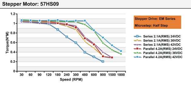


22 Appendix Speed Torque Curves for Pre-Matching Leadshine Motors 16
23 Twelve Month Limited Warranty Leadshine Technology Co., Ltd. warrants its products against defects in materials and workmanship for a period of 12 months from shipment out of factory. During the warranty period, Leadshine will either, at its option, repair or replace products which proved to be defective. Exclusions The above warranty does not extend to any product damaged by reasons of improper or inadequate handlings by customer, improper or inadequate customer wirings, unauthorized modification or misuse, or operation beyond the electrical specifications of the product and/or operation beyond environmental specifications for the product. Obtaining Warranty Service To obtain warranty service, a returned material authorization number (RMA) must be obtained from customer service at before returning product for service. Customer shall prepay shipping charges for products returned to Leadshine for warranty service, and Leadshine shall pay for return of products to customer. Warranty Limitations Leadshine makes no other warranty, either expressed or implied, with respect to the product. Leadshine specifically disclaims the implied warranties of merchantability and fitness for a particular purpose. Some jurisdictions do not allow limitations on how long and implied warranty lasts, so the above limitation or exclusion may not apply to you. However, any implied warranty of merchantability or fitness is limited to the 12-month duration of this written warranty. Shipping Failed Product If your product fail during the warranty period, customer service at to obtain a returned material authorization number (RMA) before returning product for service. Please include a written description of the problem along with contact name and address. Send failed product to distributor in your area or: ULeadshine Technology Co., Ltd. 3/F, Block 2, Nanyou Tianan Industrial Park, Nanshan Dist, Shenzhen, China.U Also enclose information regarding the circumstances prior to product failure. 17
ii Leadshine reserves the right to make changes without further notice to any products herein to improve reliability, function or design. Leadshine do
 Hardware Installation Manual for EM Series Stepper Drives www.leadshine.com ii Leadshine reserves the right to make changes without further notice to any products herein to improve reliability, function
User s Manual. Extremely Low Noise 3-phase Microstepping Driver. For 3L583M. Version All Rights Reserved
 User s Manual For Extremely Low Noise 3-phase Microstepping Driver Version 1.0 2008 All Rights Reserved Attention: Please read this manual carefully before using the driver! The content in this manual
User Manual For DM332T. 2-Phase Digital Stepper Drive. Designed by StepperOnline. Manufactured by Leadshine
 User Manual For DM332T 2-Phase Digital Stepper Drive Designed by StepperOnline Manufactured by Leadshine #7 Zhongke Road, Jiangning, Nanjing, China T: 0086-2587156578 Web site: www.omc-stepperonline.com
Hardware Installation Manual Integrated BLDC Servo Motor
 Hardware Installation Manual Integrated BLDC Servo Motor Version 1.0.0 http://www.leadshine.com Safety Items! Caution Make sure the power supply voltage dose not exceed the drive s input range. Double
PSR5042. Stepper Motor Drive User s Manual. Version 1.0. Contacts: Technical support: Sales information:
 This manual contains reserved and proprietary information. All rights are reserved. It may not be copied, disclosed or used for any purposes not expressly authorized by PrimoPal Motor. PrimoPal Motor reserves
Hardware Manual of Easy Servo Drives ES-D Series
 Hardware Manual of Easy Servo Drives ES-D Series Version 0.1.0 http://www.leadshine.com ii Safety Items! Notice Read this manual carefully before trying to install the stepper drive into your system. The
User Manual of 3M583
 ECG-SAVEBASE EMAIL:EBAY@SAVEBASE.COM WEB: HTTP://STORES.EBAY.CO.UK/SAVEBASE User Manual of 3M583 High Performance Microstepping Driver ECG-SAVEBASE ECG Safety Statement Easy Commercial Global is not liable
PSR3015. Stepper Motor Drive User s Manual. Version 1.0. Contacts: Technical support: Sales information:
 This manual contains reserved and proprietary information. All rights are reserved. It may not be copied, disclosed or used for any purposes not expressly authorized by PrimoPal Motor. PrimoPal Motor reserves
User Manual DM556T. 2 Phase Digital Stepper Drive. Designed by StepperOnline Manufactured by Leadshine 2017 All Rights Reserved
 User Manual DM556T 2 Phase Digital Stepper Drive Designed by StepperOnline Manufactured by Leadshine 2017 All Rights Reserved Address: #7 Zhongke Road, Jiangning, Nanjing, China Tel: 0086-2587156578 Web:
DM542E. User Manual. 2 Phase Digital Stepper Drive Leadshine Technology Co., Ltd. Revision 1.0
 User Manual DM542E 2 Phase Digital Stepper Drive Revision 1.0 2016 Leadshine Technology Co., Ltd. Leadshine Technology Co., Ltd (Headquarters) Address: Floor 11, Block A3, ipark 1001 Xueyuan Avenue Shenzhen,
Hardware Installation Manual
 Hardware Installation Manual Of the Easy servo Drives Version 0.0.1 http://www.leadshine.com ii Safety Items! Notice Read this manual carefully before trying to install the stepper drive into your system.
EM806 2-phase Digital Stepper Drive
 EM806 2-phase Digital Stepper Drive 24-80V, 0.35-6A, Sensorless Stall Detection, Pre-Matching Motor Sensorless stall detection eliminates cost of feedback devices and time of cable connection Super-low
EM556S Digital Stepper Drive User Manual. User Manual EM556S. Digital Stepper Drive. Revision All Rights Reserved
 User Manual EM556S Digital Stepper Drive Revision 1.0 2017 All Rights Reserved Important Notice Read this manual carefully before any assembling and using. Incorrect handling of products in this manual
EM705 2-phase Digital Stepper Drive
 EM705 2-phase Digital Stepper Drive 20-70V, 0.35-5A, Sensorless Stall Detection, Pre-Matching Motor Sensorless stall detection eliminates cost of feedback devices and time of cable connection Super-low
User Manual CL57T. Closed Loop Stepper Drive.
 User Manual CL57T Closed Loop Stepper Drive Notice Read this manual carefully before any assembling and using. Incorrect handling of products in this manual can result in injury and damage to persons and
KL-8056D. Table of Contents. Fully Digital Stepping Driver
 Contents KL-8056D Fully Digital Stepping Driver Attention: Please read this manual carefully before using the driver! Table of Contents 1. Introduction, Features and Applications...1 Introduction...1 Features...1
Hybrid AC Driver [GCNC-1110]
![Hybrid AC Driver [GCNC-1110]](/thumbs/86/94474371.jpg "Hybrid AC Driver [GCNC-1110]") Page 1 Installation Manual and Datasheet Page 2 Key Features Smooth and quiet operation at all speeds and extremely low motor heating Industrial grade performance for an alternating current servo motor
Page 1 Installation Manual and Datasheet Page 2 Key Features Smooth and quiet operation at all speeds and extremely low motor heating Industrial grade performance for an alternating current servo motor
User s Manual. Fully Digital Stepping Drive. For DM442. Version All Rights Reserved
 The content in this manual has been carefully prepared and is believed to be accurate, but no responsibility is assumed for inaccuracies. User s Manual For DM442 Fully Digital Stepping Drive Version 1.0
KL-4042D Fully Digital Stepping Drive
 KL-4042D Fully Digital Stepping Drive Version 1.0 2010 All Rights Reserved Attention: Please read this manual carefully before using the drive! Table of Contents 1. Introduction, Features and Applications...
Datasheet-MA860 Stepper Motor Driver
 Datasheet-MA860 Stepper Motor Driver Introduction The MA860 is an economical micro-stepping driver based on patented technology of EDRIVE. It is suitable for driving 2-phase and 4-phase hybrid stepping
CS-D508. User Manual. Closed Loop Stepper Drive Leadshine Technology Co., Ltd. Revision 3.1
 User Manual CS-D508 Closed Loop Stepper Drive CS-D508 Closed Loop Stepper Drive User Manual Version 3.1 Revision 3.1 2018 Leadshine Technology Co., Ltd. Leadshine Technology Co., Ltd (Headquarters) Address:
Users Manual. For P808. High Performance Microstepping Driver
 Users Manual For P808 High Performance Microstepping Driver Thank you for purchasing the Astrosyn P808 drive. Please read this manual thoroughly before installing and operating the driver, and always keep
AM882. User s Manual For. Fully Digital Stepping Drive. Version All Rights Reserved
 User s Manual For AM882 Fully Digital Stepping Drive Version 1.0 2010 All Rights Reserved Attention: Please read this manual carefully before using the drive! The content in this manual has been carefully
SDM / 4 Phase Stepper Drive Module. Compact Size & High Power Density, 20-60VDC, 6A Peak. Version 1.0
 SDM660 2 / 4 Phase Stepper Drive Module Compact Size & High Power Density, 20-60VDC, 6A Peak Version 1.0 http://www.leadshine.com / http://www.leadshineusa.com 2013 Leadshine Technology Co., Ltd. 3/F,
FEATURES: DESCRIPTION: APPLICATIONS: SPECIFICATIONS: Electrical Specifications of Drive: Operating Environment: [Geben Sie Text ein]
![FEATURES: DESCRIPTION: APPLICATIONS: SPECIFICATIONS: Electrical Specifications of Drive: Operating Environment: [Geben Sie Text ein]](/thumbs/93/111844613.jpg "FEATURES: DESCRIPTION: APPLICATIONS: SPECIFICATIONS: Electrical Specifications of Drive: Operating Environment: [Geben Sie Text ein]") ist-09 ist-0 FEATURES: Integrated compact size for saving mounting space & setup time, and reducing electrical interference Anti-Resonance provides optimal torque and nulls mid-range instability Motor
ist-09 ist-0 FEATURES: Integrated compact size for saving mounting space & setup time, and reducing electrical interference Anti-Resonance provides optimal torque and nulls mid-range instability Motor
Pamoco SpA - via Riccardo Lombardi 19/ Milano - tel fax
 By detecting motor voltage, current, and back-emf Precision current control technology Most stepper systems resonate at mid-range speed signal, Leadshine digital drives can detect loss-ofsynchronization
Hardware Installation Manual MX Axis Stepper Drive with Breakout Board & I/O s
 Hardware Installation Manual MX3660 3-Axis Stepper Drive with Breakout Board & I/O s Version 1.0 11 / 2013 Hardware Manual for MX3660 3-Axis Stepper Drive with Breakout Board & I/O s ii Notice Read this
2L415B High Performance-Cost ratio 2-phase Microstepping Driver
 User s Manual High Performance-Cost ratio 2-phase Microstepping Driver VER 2.0 Appreciate your selection of MotionKing TM driver. To make full use of its versatile performance, please read this manual
Hardware Installation Manual MX Axis Stepper Drive with Breakout Board & I/O s
 Hardware Installation Manual MX3660 3-Axis Stepper Drive with Breakout Board & I/O s Version 1.1 12 / 2013 http://www.leadshine.com http://www.leadshineusa.com 2013 Leadshine Technology Co., Ltd. Hardware
3-Axis Stepper Drive Datasheet MX3660
 3-Axis Stepper Drive Datasheet MX3660 3-Axis Stepper Drive + Breakout Board, 20-60VDC, 6A Peak Version 0.0.2 http://www.leadshine.com Features Three individual stepper drive boards Suitable for NEMA17
Datasheet MX Axis Stepper Drive with Breakout Board & I/O s. Version
 Datasheet MX3660 3-Axis Stepper Drive with Breakout Board & I/O s Version 1.1 http://www.leadshine.com http://www.leadshineusa.com 2013 Leadshine Technology Co., Ltd. Notice This manual is not for use
ADVANCED MICRO SYSTEMS
 Overview... 3 Included in the Box:... 3 Pinout... 4 Installation... 5 Power Supply... 6 Stepping Motors... 7 DIP Switch (JP1) Location... 8 Setting the Output Current (JP1)... 8 Microstep Resolution (JP1)...
MSD980 Microstepping Drive
 MSD980 Microstepping Drive Introduction MSD980 is a high-performance microstepping drive based on most advanced technology in the world today. It is suitable for driving any 2-phase and 4-phase hybrid
Datasheet MX Axis Stepper Drive with Breakout Board & I/O s. Version
 Datasheet MX4660 4-Axis Stepper Drive with Breakout Board & I/O s Version 1.0 http://www.leadshine.com http://www.leadshineusa.com 2014 Leadshine Technology Co., Ltd. Notice This document is not for use
MSD325 Microstepping Drive
 MSD325 Microstepping Drive Introduction MSD325 is a very small size microstepping drive based on most advanced technology in the world today. It is suitable for driving any 2-phase and 4-phase hybrid stepper
Integrated Stepper Drive & Motor
 SMD23 Integrated Stepper Drive & Motor Manual #: 940-0S050 User Manual AMCI Motion Control Products Important User Information The products and application data described in this manual are useful in a
Overview Included in the Box: Pinout Installation Power Supply Stepping Motors DIP Switch (JP1) Location...
 Location...") DRV7 USERS GUIDE Overview... 3 Included in the Box:... 4 Pinout... 4 Installation... 5 Power Supply... 6 Stepping Motors... 8 DIP Switch (JP1) Location... 9 Setting the Output Current (JP1)... 9 Microstep
DRV7 USERS GUIDE Overview... 3 Included in the Box:... 4 Pinout... 4 Installation... 5 Power Supply... 6 Stepping Motors... 8 DIP Switch (JP1) Location... 9 Setting the Output Current (JP1)... 9 Microstep
Manual of 2-phase hybrid stepper motor driver DQ542MA
 Manual of 2-phase hybrid stepper motor driver DQ542MA Introduction: DQ542MA is a type of two-phase hybrid stepping motor driver, the drive voltage of which is from 18VDC to 5VDC. It is designed for use
SMD Series Integrated Stepper Driver and Motor Revision 1.3
 The AMCI Integrated Stepper Motor and Microstepping Drive Combination represents the future of Stepper Motor Control applications. The SMD is a self-contained stepper motor and driver package, capable
Hardware Installation Manual MX Axis Stepper Drive with Breakout Board & I/O s
 Hardware Installation Manual MX3660 3-Axis Stepper Drive with Breakout Board & I/O s Version 1.2 3 / 2015 http://www.leadshine.com http://www.leadshineusa.com 2015 Leadshine Technology Co., Ltd. Hardware
Datasheet MX Axis Stepper Drive with Breakout Board & I/O s. Version1.0
 Datasheet MX3660 3-Axis Stepper Drive with Breakout Board & I/O s Version1.0 1. Features Power up to 3 stepper motors of NEMA 17, 23, 24, or 34 Sophisticated stepper motor control based on latest DSP technology
TB6600 Stepper Motor Driver
 TB6600 Stepper Motor Driver V1.0 07 2018 Open Source Mechatronics LTD 2018 Safety Statement The author of this document is not liable or responsible for any accidents, injuries, equipment damage, property
R325P Single Axis Driver
 R325P Single Axis Driver User Manual And Commands Guide Version 1.3 Thank you for purchasing the R325P Single-Axis Step & Direction Driver. This product is warranted to be free of manufacturing defects
G540 MANUAL MULTIAXIS STEP MOTOR DRIVE
 G540 MANUAL MULTIAXIS STEP MOTOR DRIVE PRODUCT DIMENSIONS PHYSICAL AND ELECTRICAL RATINGS Minimum Maximum Units Supply Voltage 18 50 VDC Motor Current 0 3.5 A Power Dissipation 1 13 W Short Circuit Trip
FARES PCB. General Description. Figure 1. FIPSD10M Driver Board
 FARES PCB FARES Industrial Products Bipolar Stepper Driver General Description Driving stepper motor is common necessity in most robotic projects. A stepper motor is a brushless, synchronous electric motor
Preliminary Datasheet MX Axis Stepper Drive with Breakout Board & I/O s. Preliminary V1.0
 Preliminary Datasheet MX4660 4-Axis Stepper Drive with Breakout Board & I/O s Preliminary V1.0 Features Power up to 4 stepper motors of NEMA 17, 23, 24, or 34 Sophisticated stepper motor control based
FARES PCB. General Description. Figure 1. FIPSD3.5M Driver Board
 FARES PCB FARES Industrial Products Bipolar Stepper Driver General Description Driving stepper motor is common necessity in most robotic projects. A stepper motor is a brushless, synchronous electric motor
ST400C-NT USER S GUIDE. Table of Contents
 ST400C-NT USER S GUIDE Table of Contents Board Overview Block Diagram Disclaimer Introduction Features 1 Quick Start 2 Function Description Host Interface and Communication with PC's 3 Networking Operation
LCMM024: DRV8825 Stepper Motor Driver Carrier,
 LCMM024: DRV8825 Stepper Motor Driver Carrier, High Current The DRV8825 stepper motor driver carrier is a breakout board for TI s DRV8825 microstepping bipolar stepper motor driver. The module has a pinout
Resolver to Digital Expansion Board
 Resolver to Digital Expansion Board Catalog No. EXB009A01 Installation and Operating Manual 6/98 MN1313 Table of Contents Section 1 General Information............................. 1-1 Introduction....................................
G540 User Manual. Date Modified: March 5, 2012 Page 1 of 10
 G540 User Manual Date Modified: March 5, 2012 Page 1 of 10 DIMENSIONS PHYSICAL AND ELECTRICAL RATINGS Minimum Maximum Units Supply Voltage 18 50 VDC Motor Current 0 3.5 A Power Dissipation 1 13 W Short
MP6500 Stepper Motor Driver, Digital Current Control
 This breakout board for the MPS MP6500 micro stepping bipolar stepper motor driver is Pololu s latest stepper motor driver. The module has a pinout and interface that are very similar to that of our popular
Stepper motor driver HEM-545 last change:
 Documentation for Stepper motor driver HEM-545 last change: 16.03.2011 Functional description HEM-545 is a one channel motor driver for 2-phase stepping motors with pulse and direction interface. Motor
G540 4-AXIS DRIVE REV 4: MAY 28, 2010
 Thank you for choosing to purchase the G540 4-Axis Drive System. If you are dissatisfied with it for any reason at all within two weeks of its purchase date, you may return it for a full refund provided
SD17098IX Specifications Networked Stepper Driver & Indexer Revision 0.0
 The SD17098IX is a 170V 9.8amp stepper driver and indexer combination that communicates on a Network. The available networks, along with the corresponding AMCI part numbers, are shown in the following
P-Series Drive Features and Benefits
 P-Series Drive Features and Benefits P000 P000 P000 Value DC Input Stepper Drive Wave matching for Kollmorgen motors to provide optimal performance All inputs and outputs are optically isolated Step and
TECHNICAL REFERENCE BSD V-3A Bipolar Stepper Driver
 TECHNICAL REFERENCE BSD 3630 36V-3A Bipolar Stepper Driver Contents Chapter 1 Safety Precautions.. 3 Chapter 2 Drive Overview...4 2.1 Key Features...4 2.2 Drive Description...4 2.3 Applications. 4 Chapter
PMDX-170 Slotted Optical Sensor
 PMDX-170 Slotted Optical Sensor User s Manual Date: 20 May 2009 PMDX Web: http://www.pmdx.com 9704-D Gunston Cove Rd Phone: +1 (703) 372-2975 Lorton, VA 22079-2366 USA FAX: +1 (703) 372-2977 PMDX-170_Manual_10.doc
V E2B Snap-in I/O Module
 i4 Automation Ltd - 01480 395256 V200-18-E2B Snap-in I/O Module The V200-18-E2B plugs directly into the back of compatible Unitronics OPLCs, creating a selfcontained PLC unit with a local I/O configuration.
A4988 Stepper Motor Driver Carrier
 A4988 Stepper Motor Driver Carrier A4983/A4988 stepper motor driver carrier with dimensions. Overview This product is a carrier board or breakout board for Allegro s A4988 DMOS Microstepping Driver with
PMDX-108-Output. 8-Channel Isolated Output Board for PC parallel port pins 2-9. User s Manual
 PMDX-108-Output 8-Channel Isolated Output Board for PC parallel port pins 2-9 User s Manual Date: 25 February 2010 PMDX Web: http://www.pmdx.com 9704-D Gunston Cove Rd Phone: +1 (703) 372-2975 Lorton,
TB6600 Stepper Motor Driver User Guide
 TB6600 Stepper Motor Driver User Guide Version: V1.2 Contents 1. Introduction... 1 Features:... 1 Electric Specification:... 1 INPUT & OUTPUT:... 2 2. Stepper Motor Wiring:... 4 3. Microcontroller Connection
STEPPER MOTOR DRIVES SOME FACTORS THAT WILL HELP DETERMINE PROPER SELECTION
 SOME FACTORS THAT WILL HELP DETERMINE PROPER SELECTION Authored By: Robert Pulford and Engineering Team Members Haydon Kerk Motion Solutions This white paper will discuss some methods of selecting the
V E1B Snap-in I/O Module
 V200-18-E1B Snap-in I/O Module The V200-18-E1B plugs directly into the back of compatible Unitronics OPLCs, creating a selfcontained PLC unit with a local I/O configuration. Features 16 isolated digital
MBC25SI1TB. Programmable Simple Indexer/Driver. User s Guide E. Landon Drive Anaheim, CA
 MBC25SI1TB Programmable Simple Indexer/Driver User s Guide A N A H E I M A U T O M A T I O N 4985 E. Landon Drive Anaheim, CA 92807 e-mail: info@anaheimautomation.com (714) 992-6990 fax: (714) 992-0471
A4988 Stepper Motor Driver Carrier with Voltage Regulators
 1 of 6 12/2/2011 6:37 PM A4988 Stepper Motor Driver Carrier with Voltage Regulators Pololu item #: 1183 26 in stock Price break Unit price (US$) 1 19.95 10 17.95 100 13.97 Quantity: backorders allowed
RHINO MOTION CONTROLS RMCS-1120 Hybrid Servo Driver with Modbus RTU communication (Max. 50Vdc and 7A per phase)
") Installation Manual and Datasheet Page 1 Key Features Smooth and quiet operation at all speeds and extremely low motor heating Industrial grade performance for an alternating current servo motor Field
Installation Manual and Datasheet Page 1 Key Features Smooth and quiet operation at all speeds and extremely low motor heating Industrial grade performance for an alternating current servo motor Field
Designing a NextMove PCI Breakout Unit
 Designing a NextMove PCI Breakout Unit MN1277BU Issue 1.0 MN1277BU 05/2000 . Copyright and Safety Information Copyright Baldor Optimised Control Ltd 2000. All rights reserved. This manual is copyrighted
DMX-K-DRV Integrated Step Motor Driver Manual
 Tu Sitio de Automatización! DMX-K-DRV Integrated Step Motor Driver Manual Table of Contents 1. Introduction... 4 2. Part Numbering Scheme... 4 3. Dimensions... 5 NEMA 11 DMX-K-DRV... 5 NEMA 17 DMX-K-DRV...
A4988 Stepper Motor Driver Carrier, Black Edition
 A4988 Stepper Motor Driver Carrier, Black Edition A4988 stepper motor driver carrier, Black Edition, bottom view with dimensions. Overview This product is a carrier board or breakout board for Allegro
V E1B Snap-in I/O Module
 V200-18-E1B Snap-in I/O Module The V200-18-E1B plugs directly into the back of compatible Unitronics OPLCs, creating a selfcontained PLC unit with a local I/O configuration. Features 16 isolated digital
PCL451. Manual Preset Indexer. User s Guide E Landon Drive, Anaheim, CA
 PCL451 Manual Preset Indexer User s Guide A N A H E I M A U T O M A T I O N 4985 E Landon Drive, Anaheim, CA 92807 e-mail: info@anaheimautomation.com (714) 992-6990 fax: (714) 992-0471 website: www.anaheimautomation.com
User Manual. UIM240XX Series Parallel Signal Control Miniature Integrated Stepper Motor Driver
 User Manual UIM240XX Series Parallel Signal Control Miniature Integrated Stepper Motor Driver UIM24002/04/08 Please pay attention to the following before using the UIROBOT products: UIROBOT products meet
SINCOS. Linear Stepper Motor Power Stage. Manual 2066-A006 GB
 SINCOS Linear Stepper Motor Power Stage Manual 2066-A006 GB phytron SINCOS Linear Stepper Motor Power Stage for Bipolar Control Mode Manual 2066-A006 GB Manual SINCOS 2002 All rights with: Phytron GmbH
PMDX-105 Quad Isolator Board
 PMDX105 Quad Isolator Board User s Manual Date: 18 April 2011 PMDX Web: http://www.pmdx.com 9704D Gunston Cove Rd Phone: 1 (703) 3722975 Lorton, VA 220792366 USA FAX: 1 (703) 3722977 PMDX105_Manual_10.doc
D115 The Fast Optimal Servo Amplifier For Brush, Brushless, Voice Coil Servo Motors
 D115 The Fast Optimal Servo Amplifier For Brush, Brushless, Voice Coil Servo Motors Ron Boe 5/15/2014 This user guide details the servo drives capabilities and physical interfaces. Users will be able to
P7000 Stepper Drives. P7000 Introduction
 P7 Introduction P7 Stepper Drives Danaher Motion introduces the P7 Series Stepper Drives. Previously unheard of stepper features allow the P7 to provide true servo-like performance at a fraction of the
DMX-K-DRV. Integrated Step Motor Driver + (Basic Controller) Manual
 Manual") DMX-K-DRV Integrated Step Motor Driver + (Basic Controller) Manual Table of Contents 1. Introduction... 4 Features... 4 2. Part Numbering Scheme... 5 3. Electrical and Thermal Specifications... 6 Power
DMX-K-DRV Integrated Step Motor Driver + (Basic Controller) Manual Table of Contents 1. Introduction... 4 Features... 4 2. Part Numbering Scheme... 5 3. Electrical and Thermal Specifications... 6 Power
Master Pulse Reference/ Isolated Pulse Follower Expansion Board
 Master Pulse Reference/ Isolated Pulse Follower Expansion Board Catalog No. EXB005A01 Installation and Operating Manual 2/03 MN1312 Y1 Table of Contents Section 1 General Information.............................
PMDX-105. I/O Option Riser Board User s Manual. Document Revision: 1.1 Date: 7 September 2004 PCB Revision: PCB-443A
 PMDX-105 I/O Option Riser Board User s Manual Date: 7 September 2004 PMDX Web: http://www.pmdx.com 7432 Alban Station Blvd., A105 Phone: +1 (703) 912-4991 Springfield, VA 22150-2321 USA FAX: +1 (703) 912-5849
Contents. HP E1586A Rack Mount Terminal Panel User s Manual
 Contents HP E1586A Rack Mount Terminal Panel User s Manual Description... 5 Connecting to VXIbus Instruments... 5 Interconnect Cables... 5 Terminal Block Connections... 6 Using the Terminal Panel for Reference
Novusun Controller Wiring and MACH3 Software Setup
 Novusun Controller Wiring and MACH3 Software Setup V1.0 01 2019 Open Source Mechatronics LTD 2019 Safety Statement The author of this document is not liable or responsible for any accidents, injuries,
PLC-24V10AL(-PT/-TH) Quick Start Manual (Rev.1.10)
 Quick Start Manual (Rev.1.10)") TEC (Peltier) Controller PLC-24V10AL(-PT/-TH) Quick Start Manual (Rev.1.10) Thank you for purchasing the TEC (Peltier) Controller PLC-24V10AL. Read these operating instructions carefully to ensure effective
TEC (Peltier) Controller PLC-24V10AL(-PT/-TH) Quick Start Manual (Rev.1.10) Thank you for purchasing the TEC (Peltier) Controller PLC-24V10AL. Read these operating instructions carefully to ensure effective
High Speed Remote I/O Module
 High Speed Remote I/O Module EXF-RC15 The Unitronics EXF-RC15 is a High Speed Remote I/O Module that offers three High Speed Counter inputs and four high speed outputs. Overall, the EXF-RC15 offers 9 digital
V E2B Snap-in I/O Module
 V200-18-E2B Snap-in I/O Module The V200-18-E2B plugs directly into the back of compatible Unitronics OPLCs, creating a selfcontained PLC unit with a local I/O configuration. Features 16 isolated digital
MD3. Microstepping Motor Driver Page 1 of 7. Description. Software. Mechanical Drawing. Features
 Page 1 of 7 The MD3 is a stepper motor driver with an integrated motion controller that is capable of driving size 14 to 42 stepper motors from 2 to 256 microsteps per step. Peak motor currents are selectable
Brushless DC Motor Driver CBM-105 FN/FP User Manual
 Brushless DC Motor Driver CBM-105 FN/FP User Manual Thank you for purchasing an Itoh Denki CBM-105 series motor driver. Please read this manual before operating the product, and keep this manual readily
Stepper Drive Setup Guide
 MACHMOTION Stepper Drive Setup Guide 1/21/2011 Everything you need to know to connect your stepper motors to the MachMotion stepper drives. MachMotion Version 1.0.1 2 P a g e Copyright 2011, MachMotion.com
AC4G-D User s Manual
 AC4G-D User s Manual Entire contents of this manual 2004 Active Cool Ltd. Ashkelon, Israel. Reproduction in whole or in part without permission is prohibited. Active Cool and AC4G-D are registered of Active
BB-303 Manual Baseboard for TMCM-303
 BB-303 Manual Baseboard for TMCM-303 Trinamic Motion Control GmbH & Co. KG Sternstraße 67 D 20357 Hamburg, Germany http://www.trinamic.com BB-303 Manual (V1.04 / Jul 9th, 2007) 2 Contents 1 Features...
ME15 Magnetic Encoder Manual Revision 1.1
 Product Overview The ME15 Magnetic Encoder is the newest addition to AMCI s Encoder product line. The encoder is designed for lower resolution and lower cost applications and provides 10 bits of resolution.
IO-DI8-TO8, IO-DI8-TO8-L I/O Expansion Modules 8 Inputs, 8 Outputs
 IO-DI8-TO8, IO-DI8-TO8-L I/O Expansion Modules 8 Inputs, 8 Outputs The IO-DI8-TO8 and IO-DI8-TO8-L are I/O expansion modules that can be used in conjunction with specific Unitronics OPLC controllers. The
General Description. Figure 1. FIPSD2M Driver Board
 FARES Industrial Products Bipolar Stepper Driver General Description Driving stepper motor is common necessity in most robotic projects. A stepper motor is a brushless, synchronous electric motor that
KL1108 Closed Loop Stepping System
 KL1108 Closed Loop Stepping System 1. Introduction Descriptions KL1108 is a new generation hybrid servo driver, it combines the advantage of both the servo system and stepper system,the system acts as
When any of the following symbols appear, read the associated information carefully. Symbol Meaning Description
 Vision OPLC V350-35-R34/V350-J-R34 Installation Guide The Unitronics V350-35-R34/V350-J-R34 offers the following onboard I/Os: 22 Digital Inputs, configurable via wiring to include 2 Analog and 3 HSC/Shaft-encoder
AMAX-2750SY Series. 32-ch AMONet RS-485 Isolated Digital I/O Slave Modules. User Manual
 AMAX-2750SY Series 32-ch AMONet RS-485 Isolated Digital I/O Slave Modules User Manual Copyright The documentation and the software included with this product are copyrighted 2008 by Advantech Co., Ltd.
User Manual. UIM240XX Series Parallel Signal Control Miniature Integrated Stepper Motor Driver V1.2
 User Manual UIM240XX Series Parallel Signal Control Miniature Integrated Stepper Motor Driver V1.2 UIM24002/04/08 Please pay attention to the following before using the UIROBOT products: UIROBOT products
AD VL M1S + AD VM M1S AD VL M2S + AD VM M2S AD VL M3S + AD VM M3S AD VM M3SP
 Stepper Motor DRIVER Constant Voltage Mode USER MANUAL AD VL M1S + AD VM M1S AD VL M2S + AD VM M2S AD VL M3S + AD VM M3S AD VM M3SP Page 2 of 23 Release tracking File Description Date V4900UM230904_VD-R0
User Manual. UIM240XX Series Parallel Signal Control Miniature Integrated Stepper Motor Driver
 User Manual UIM240XX Series Parallel Signal Control Miniature Integrated Stepper Motor Driver UIM24002/04/08 Please pay attention to the following before using the Mach Motion products: - Mach Motion products
LNX Series Motor and Drives
 LNX Series Motor and Drives Operator's Manual PN 04-01808 x PRECISION MOTION CONTROLS 2530 Berryessa Rd. #209 San Jose, CA 95132 1 2 Table of Contents Page Introduction 1. Description 3 2. Warranty 4 Installation