Integrated Valvejet 9 Dot Print Head
|
|
|
- Chastity Gallagher
- 6 years ago
- Views:
Transcription
1 Integrated Valvejet 9 Dot Print Head What am I getting? What are the improvements? Diagraph is proud to release the new IV9 Dot print head. New features include: Environmentally Sealed housing for harsh environments LED Display Channel purge button built into the head First dot correction Electronic dot size Correction on the print head Ability to read pressure on the display Compatible with IJ3000 and Series 1 Systems See page 5 for more details. What does the new print head replace? New Print head P500 - ASSY,IV9DOT PRNT HD,1/2",POR N500 - ASSY,IV9DOT PRNT HD,1/2",NP P875 - ASSY,IV9DOT PRNT HD,7/8",POR N875 - ASSY,IV9DOT PRNT HD,7/8",NP Replaces PH,IV 1/2",POR PH,IV,1/2" POR,ENVIRONMENTAL PH,IV 1/2",NP PH,IV,1/2" NP,ENVIRONMENTAL PH,IV,7/8" POR PH ASSY,7/8" 9-DOT POR SP PH,IV,7/8" NP PH,7/8" 9-DOT,NP,SP Can I get the old style print head? Previous designs are available in our remanufactured program. The remanufactured program will have a price increase that will go into effect on 12/1/06. The old print head design will no longer be available after 1/31/07. Will the new print head fit onto my existing production line that already has old style print heads? The dimensions between the old style print head and new style print head are different. Less correction may be needed if heads are replaced from downstream (last print head to print on the product) to upstream (first print head to print on the product) on your production line. See page 7 and 8 for drawing. How can I tell if I need an adapter for the new head to fit my brackets? If your brackets are round in shape you will need an adapter for the new style print head. Round brackets are typical for a Series 1 system, which should be five years or older. The part number for the adapter bracket is $55. Print heads used with an IJ3000 should not need an adapter, these systems have shipped with 80/20 brackets and are compatible with the new print heads. See page 9 for drawing

2 Can I use my current ink? Yes, your current Series 1 and IJ3000 IV System ink will work with the new IV 9 Dot print head. What are the dimensions of the new print head vs. the old print head? Dimensions can be found on our website See included dimensional drawing page 7 and 8. What will I need to change when I get the new print head? Because the new print head does not have the same dimensions as the old style print head it may be necessary to adjust the distance from the photocell to the print head on an IJ3000 system (refer to IJ3000 Manual P# Rev D page 26 for instruction). Adjustments to the position of the new IV9 Dot head may also be needed to align the printed text with other print heads on the production line. What are the part numbers I need to order if I have old brackets? You will need an adapter (P# ) if you have brackets that are round (tubular) in shape. See page
3 What does the new print head look like? A picture of the new head is included in this packet. See page 6. Can I have my old style print head repaired? Repairs on the old style print head will no longer be available after 1/31/07. Can I exchange my old head for a new style print head? Yes, if you want to move forward with the new improved head design you can do so today. New IV 9 Dot print heads are available for a 10% discount off list price through December Can I exchange my new style print head for an old style print head? No, the old design head is not manufactured as new any longer and is only available on the print head exchange program for a limited time. Will the new head plug in and print? Yes, the new style print head will be able to be plugged in and print right away on a Series 1 and IJ3000 system, you may need to adjust the print head to photocell distance on your IJ3000 controller. The new IV9 dot print head is not compatible with Telemark systems. How do I install the new head? Diagraph technicians are trained to install the new IV 9 dot print heads and are available to assist your company with the installation of new IV 9 dot print head(s). Installation instructions are also included in this packet. See page 10. How do I use the new features via the display and push buttons on the back of the print head? Instructions on how to use the display and buttons on the back of the new IV 9 dot print head are included in this packet. See page 11. How does a Diagraph Integrated Valvejet Print Head work? Documentation discussing the theory of operation for an Integrated Valvejet Print Head is included in this packet. See page 12. Who do I call if I have more questions? Diagraph Customer Service and Technical Support can be reached at (7:00am -5:00pm CST). We are happy to help answer any questions you may have. You can also visit
4 New IV9 Dot systems are being sold with a more robust style of 80/20 bracketry, how can I get that style of bracket for my other lines? The more robust style bracket that is being shipped with new IJ3000 IV systems are twice the width of the single (1.5 ) pole 80/20 brackets. Both styles, the single (1.5 ) pole and the double (3 ) pole 80/20 brackets are compatible with the new IV9 Dot print heads. If you prefer the more robust style single head conveyor bracket, you can order part number $85 to upgrade your existing lines to the double pole bracket. Reference Mounting differences Old vs. New illustration below on this page. See page 13 for additional drawing. Quick Reference Chart: Controller Type Bracket Type What do I need Other Option IJ3000 IV System sold 80/20 Double (3 ) Current NO Current NO from 11/ Present Pole=NEW UPGRADE NEEDED UPGRADE NEEDED IJ3000 IV System sold from /2006 COMPATIBLE 80/20 single (1.5 ) pole=old COMPATIBLE Single (1.5 ) poles are Compatible with IV9 Dot Upgrade bracket to double (3 ) pole bracket P# Series 1 System Round Bracket Pole adapter plate Upgrade bracket to double (3 ) pole bracket P# Telemark System NOT COMPATIBLE NOT COMPATIBLE NOT COMPATIBLE Mounting differences Old vs. New Configuration "A" 8 10 Configuration "B" OLD NEW - 4 -

5 IV9DOT-500 & IV9DOT-875 Print Head Features o One-piece die-cast Aluminum housing o Pre-formed high temperature tubing o LED display and membrane switch Built-in pressure gauge Channel purge at print head: Individual or all channels Pulse width adjustment at your finger tip o Automatic 1 st Dot Correction First dots will print consistently End users are recommended to wipe front orifice plate for overnight startup o Overdrive protection Protection against overzealous print speeds Protection against faulty cables Display shows Er indicating the error from overdriving the print head. This sample shows missing dots from overdriving o o o o Environmentally sealed Integral mounting bracket with 90 pivot capable Photocell bracket mounting holes Flammable vapor explosion tested safely vents - 5 -
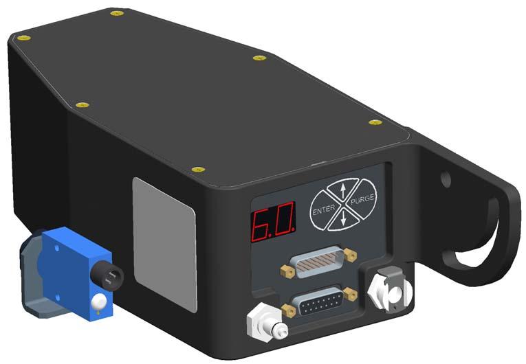
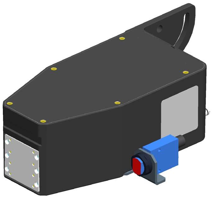
6 Integrated Valvejet 9 Dot - 6 -
7 IV9DOT & IV9DOT Print Head - 7 -
8 - 8 -
9 Adapter Plate Mounting to Round Bracketry Kit Assembly Instructions N Integrated Valve Print Head, 9 Dot, Revision A Page 1 of 1 ITEM PART NUMBER DESCRIPTION QTY PLT,ADPTR,IV9 PH TO RND BRCKTRY BRCKT,PHOTOCELL SCR,5/16-18 X ½ BUT HD CAP, SS SCR,#8-32 X 3/8 PH FL HD, 82,SS 2 Note: The photocell offset will need to be adjusted at the print head controller per the view below OLD STYLE NEW STYLE - 9 -
10 Installation Instruction Sheet N Integrated Valve Print Head, 9 Dot, Revision B Page 1 of 3 Wear safety goggles when performing the procedure.! Disconnect power during installation. INSTALLATION 1. Remove shipping tape from print head orifice plate. 2. Install print head on bracketry. Diagram 1 is an example of typical mounting. 3. Align print head with substrate. 4. Mount the regulator included with the print head.! DO NOT ATTEMPT TO CHANGE THE REGULATOR PRESSURE. IT IS SET AT THE FACTORY. 5. Ensure that the driver controller and ink delivery system have been installed. The print head electronic cable should be installed into the driver controller and routed to the print head. The ink outlet tubing (trunk line) from the ink delivery system should be installed and bled. 6. Connect the female (inlet side) of the regulator to the ink supply trunk line. 7. Connect the male (outlet side) of the regulator to the Ink Inlet, Supply Port on the rear of the print head. 8. Connect the print head electronic cable from the controller to the appropriate Print Head Cable Inlet port on the rear of the print head. 9. Every print head is shipped with a clear conditioning fluid. Connect an effluent bottle or comparable device to the Ink Outlet, Bleed Port on the rear of the print head until ink flows thru. 10. Hold an absorbent cloth(s) in front of the print head. Press and hold the PURGE button on the rear membrane switch until ink is ejecting from the print head front orifice plate. 11. While not printing or purging, the pressure on the print head LED display should be approximately 7 psi. This pressure will fluctuate while printing. 12. The print head is ready for printing
11 Installation Instruction Sheet N Integrated Valve Print Head, 9 Dot, Revision B Page 2 of 3 PRINT HEAD OPERATION (Diagram 2) Initial Startup and Power Save: When the print head is connected to the electronic cable, the display shows the center decimal point to signify there is power. This is the Power Save mode. This mode saves energy by not powering all the LED display segments. The print head has full functionality in Power Save mode. Any of the four push buttons on the membrane switch will illuminate (wake up) the display. When awake, the display will always start in the Home Screen. Inactivity: After 30 seconds of inactivity in the Home Screen, the display will change to Power Save mode. If the LED display is in any other mode such as Purge or Pulse Width Adjustment, the LED display will default to the Home Screen after 30 seconds of inactivity, then Power Save mode (an additional 30 seconds). Home Screen: The LED state after waking up the print head display or the default after 30 seconds of inactivity. It displays the print head pressure in psi (pounds per square inch). LED DISPLAY PRINT HEAD CABLE INLET PUSH BUTTON MEMBRANE SWITCH PURGE Button: The PURGE button can be used in two different ways, one, to PURGE all channels at once, or two, to PURGE one channel at a time. From the Home Screen, press and hold the PURGE button on the rear membrane switch for one second. All of the channels will fire/eject ink for two seconds. If you continue to hold the PURGE button, then the print head will purge ink until you release the button. To purge individual channels, press the ENTER button once then the up and down arrows to select the desired channel (e.g. 1 thru 9). Again, press and hold the PURGE button for one second. Ink PRINT HEAD CABLE EXIT. DAISY CHAIN TO NEXT PRINT HEAD. INK OUTLET, BLEED PORT Diagram 2 INK INLET, SUPPLY PORT will eject from the selected channel for two seconds. To return to the home screen, press the down arrow button until Pr is selected, and then press ENTER. Otherwise, the print head will automatically return to the home screen after 30 seconds of inactivity. Pulse Width Adjustment: Hold down the up and down arrows simultaneously. The last channel to be accessed will be displayed. Press the ENTER button. The pulse width setting will be displayed. This value is relative and can range between 15 and 65. The higher the value, the larger the dot size, and vice versa. Generally, pulse width adjustment on a new print head is not recommended. These values are factory set. However, it may be necessary to increase pulse widths if there are long print head cable lengths in the daisy chain. Decreasing the pulse widths will likely result in missed dots at first start-up. If a pulse width is changed, the ENTER button must be pressed to save the new value(s). Again, press the down arrow until Pr is displayed. Press ENTER to exit to the Home Screen. Note: If the ENTER button is not pressed, the display will revert to the home screen after 30 seconds and the pulse width value will not be saved. ENTER Button: This button is used to move from one function to the next or saving pulse width adjustments. Up and Down Arrows: These buttons are used to select channels, enter Pulse Width Adjustment mode, and to adjust the pulse width values up or down. Er Display Code: If the display on the rear of the print head shows a flashing decimal, this means the print head has been driven in excess of its normal printing range and is now in overdrive protection. Pressing any of the four buttons on the rear of the print head will reveal the Er code. Consult the factory. To clear the code, press the ENTER button on the rear of the print head. Note that this code will only clear when the print head is not being overdriven

12 THEORY OF OPERATION Installation Instruction Sheet N Integrated Valve Print Head, 9 Dot, Revision B Page 3 of 3 Integrated Valve inkjet technology utilizes electronically controlled solenoid valves to open and close the flow of pressurized ink thru a series of holes, channels, and small orifices. Regulated ink pressure is supplied to the rear of the print head. While the print head is printing or purging, ink is flowing thru the inlet port, tubing, filter, and finally into the valve control mechanism. When the print head printed circuit board receives data signals from the controller via the print head cable, a microcontroller on the pcb generates pulses to the appropriate solenoids. These solenoids in turn, connect directly to a sealing piston. The sealing piston presses against a membrane that seals off the flow of ink to the appropriate orifice(s). When the solenoid is energized the piston pulls away from the sealing membrane and ink pressure allows flow of ink thru that channel and out the orifice. The time that the solenoid is powered on is called the pulse width; therefore, if the pulse width is increased, the valve is allowed to flow more ink (bigger dot). Pressure is monitored via a sensor that is teed into the print head bleed tubing. The sensor sends voltage signals to the display board that are scaled and displayed as gage pressure on the rear of the print head. 9 Dot PRINT HEAD SPECIFICATIONS Weight: 5.4 lbs [2.4 kg] Enclosure: Paint over anodized Aluminum Electrical: 15 VDC input from controller Ink Filtration: 25 micron in-line Print Speed: Up to 650 ft/min (Print Resolution Dependent) Ink Type: Porous (Water Based) or Non-Porous (Alcohol or MEK based) as indicated on label. Operating Pressure: 7 psi ink input Environment: Ambient operation temperature: 40 F to 104 F (10 C to 40 C Operating humidity: 10 90% non-condensing
13 Print System Conveyor Mounting Kit Assembly Instructions N Revision A Page 1 of 1 ITEM PART NUMBER DESCRIPTION QTY X01400 BAR,1.5 X 3 X 14 LONG X01400 BAR,1.5 X 1.5 X 14 LONG BRACKET, CORNER, 3 HOLE BRACKET, CORNER, 4 HOLE END CAP, 1.5 X END CAP, 1.5 X T-NUT, DOUBLE, 5/ T-NUT, SINGLE, 5/ NUT, 5/16-18 HEX SCREW,5/16-18 X 5/8 BUTTON HD CAP,SS SCREW,5/16-18 X 1-1/2 SOC HD CAP,SS WASHER, 5/16 LOCK WASHER,5/16 FLAT 2 Note: This bracket kit can be assembled in two different configurations and can be used to mount either a 9 dot printhead or a 7 dot print system. CAUTION: When the print system is setup in configuration "B" it may be possible for the carton being printed to make contact with the ink can. Items 9, 11, 12, and 13 are used to fasten the bracket assembly to the side of the conveyor Configuration "A" 8 10 Configuration "B"
Integrated Valvejet 18 Dot Print Head. What am I getting? What are the improvements?
 Integrated Valvejet 18 Dot Print Head What am I getting? What are the improvements? Diagraph is proud to release the new IV18 Dot print head. New features include: Environmentally Sealed housing for harsh
Integrated Valvejet 7 Dot Print Head
 Integrated Valvejet 7 Dot Print Head What am I getting? What are the improvements? Diagraph is proud to release the new IV7 Dot print head. New features include: Environmentally Sealed housing for harsh
Operations Manual. IV4000 Integrated Valve System Revision B
 Operations Manual IV4000 Integrated Valve System 5770-017 Revision B 1 Missouri Research Park Drive St. Charles, MO 63304 Service Line 1-800-526-2531 Illinois Tool Works Inc 2017 IV4000 Integrated Valve
Operations Manual Integrated Valve Ink Jet System
 Operations Manual Integrated Valve Ink Jet System 5760-107 Revision G 1 Missouri Research Park Drive St. Charles, MO 63304 ServiceLine 1-800-526-2531 Illinois Tool Works Inc 2008 IJ3000 Integrated Valve
Operations Manual. Integrated Valve Print System Revision B
 Operations Manual Integrated Valve Print System 5770-448 Revision B 1 Missouri Research Park Drive St. Charles, MO 63304 Service Line 1-800-526-2531 Illinois Tool Works Inc 2014 Print System Operations
The Pro/Classic Series Printhead angle can be set between 0 and 90. Common settings are shown below. 192/32 1 Print Head
 Pro/Classic Series Printhead Instructions 2464-172 Rev. H Getting Started Head Angle The Pro/Classic Series Printhead angle can be set between 0 and 90. Common settings are shown below. 90 32-39 27 352/32
Operations Manual. IJ4000 Impulse Jet System Revision E
 Operations Manual System 5765-018 Revision E 1 Missouri Research Park Drive St. Charles, MO 63304 Service Line 1-800-526-2531 Illinois Tool Works Inc 2019 Ink Jet System Operations Manual 5765-018 The
Operations Manual. IJ4000 Impulse Jet System Revision D
 Operations Manual IJ4000 Impulse Jet System 5765-018 Revision D 1 Missouri Research Park Drive St. Charles, MO 63304 Service Line 1-800-526-2531 Illinois Tool Works Inc 2018 Ink Jet System Operations Manual
Manual. LC-16 system. LC-16 Inkjet Printer 1
 Manual LC-16 system LC-16 Inkjet Printer 1 Index ENVIRONMENT. 3 OPERATOR S SAFETY 3 OPERATION SAFETY 3 PART 1 INSTALLATION AND PARAMETER SETTING 4 1) Preparing 4 2) Installation 4 3) Priming 4 4) Parameter
Mechanically Activated Device for Dry Run Protection in Applications with LORENTZ Solar Pump Systems
 Well Probe Mechanically Activated Device for Dry Run Protection in Applications with LORENTZ Solar Pump Systems The switch can be used to detect the water level within a well. When the water level in the
ERNG-X. Description. Applications. ERNG-X Specifications DERNG2108X012
 ERNG-X DERNG2108X012 Description The ERNG-X is a steady state no bleed engineered system for accurate and reliable control of Natural Gas. The ERNG-X includes a pressure regulator, preconditioning filters,
Operations Manual WaxJet 192 System
 Operations Manual WaxJet 192 System 2466-400 Revision D 1 Missouri Research Park Drive St. Charles, MO 63304 ServiceLine 1-800-526-2531 Illinois Tool Works Inc 2007 Ink Jet System Operations Manual 2466-400
Installation and Assembly: 2 x 2 Video Wall Ceiling Mount for 40" - 55" flat Panel Displays
 Installation and Assembly: 2 x 2 Video Wall Ceiling Mount for 40" - 55" flat Panel Displays Model: DS-VWT955-2X2 EXTENSION COLUMN (SOLD SEPARATELY) COMPATIBILITY Display width must be a minimum of 36"
Procedure to Install an IO Expansion Cage Assembly in a Maxum II Modular Oven Analyzer
 Procedure to Install an IO Expansion Cage Assembly in a Maxum II Modular Oven Analyzer Difficulty Level: Medium Estimated time to execute: 1 Hour Revision History Issue Date Reason 001 5/31/2016 Initial
Ultegra Bench Scale SCB-R U USB Powered
 Service Manual Ultegra Bench Scale SCB-R9000-14U USB Powered 2009 by Fairbanks Scales Inc. All rights reserved 51221 Revision 1 09/09 Amendment Record Ultegra Bench Scale SCB-R9000-14U USB Powered 51221
Description: Detailed procedure on removing old bushing and installing new Brake Bushing Replacement Kit 10447
 Procedure: BRAKE BUSHING REPLACEMENT PROCEDURE Product: Document #: Rev: Page: MODEL 7000, 7000A, & 8000 GYRO 078 1 1 of 14 Description: Detailed procedure on removing old bushing and installing new Brake
Installation Guide. Retrofit Kit for USB Ready Intraoral Systems
 Installation Guide Retrofit Kit for USB Ready Intraoral Systems Table of Contents Wall-Mount Retrofit Kit... 2 Introduction... 2 Connecting the Articulating and Horizontal Arm Cables... 2 Installing the
Phase Loss Protection Upgrade. Phase Loss Protection Upgrade. In this bulletin:
 Phase Loss Protection Upgrade In this bulletin: Introduction... 2 Purpose... 2 General... 2 Applicability... 2 HD3070 Phase Loss Protection Upgrade Kit Parts... 2 Preparation... 4 Install the Phase Loss
DIMENSION/WEIGHT kpa. 0 to 20 m / 0 to 60 ft 0 to 2 bar / 0 to 29 psi. 0 to 50 m / 0 to 160 ft 0 to 5 bar / 0 to 72.5 psi
 V161102 Liquid Level Sensor Sensor for measuring the level of liquid in a well or tank USE / PURPOSE The range of liquid level sensors use pressure to measure the liquid level in a well or tank. The sensors
Sidewinder Pumps Inc. AC C1D2 Timer/Controller
 Sidewinder Pumps Inc. AC C1D2 Timer/Controller Page 1 of 14 Rev 4/26/17 Table of Contents 1. Warnings --------------------------------------------------------------------------------------------------
DirectCommand Installation RoGator Model Year Ag Leader Technology
 Note: Indented items indicate parts included in an assembly listed above Part Name/Description Part Number Quantity Direct Command Kit 4100801 1 Dual Lock 2000052-9 1 Dual Lock 2000053-9 1 Quick Reference
SENC 150 REFERENCE MANUAL
 SENC 50 REFERENCE MANUAL SENC 50 Table of Contents / Warnings Page Introduction / Supplied items... 4 2 Preparing the mounting / Mounting information... 5 3 Encoder dimensions... 8 4 Backup spar dimensions...
RL-H80 PARTS LIST # K
 RL-H80 PARTS LIST # 102837K USE THIS PARTS LIST FOR: Hoist Serial Number: 2733 to For older hoists use the following: Parts List No. 102837G for Serial Number 2485 to 2732 IF YOUR HOIST DOES NOT FALL WITHIN
Removal and Installation 8
 Removal and Installation 8 8 Introduction 8-2 Service Calibration Guide to Removal and Installation 8-4 Window 8-8 Covers and Trims 8-12 Rear Tray 8-31 Rear Cover 8-32 Media Lever 8-33 Media Lever Position
To be used for reference only Property of Arc Machines, Inc.
 MODEL 9-1500 IPB Notice and Revision History This document and the information contained herein is the property of Arc Machines, Inc. It is proprietary and submitted and received in confidence. It shall
DOT MATRIX PRINTER SP6000 SERIES
 DOT MATRIX PRINTER SP6000 SERIES Hardware Manual < Approval: CEL > Trademark acknowledgments SP6000 : Star Micronics Co., Ltd. Notice All rights reserved. Reproduction of any part of this manual in any
G12/G12x USER S MANUAL
 G12/G12x USER S MANUAL TABLE OF CONTENTS SECTION 1 SLIDE CONFIGURATION SECTION 2 SLIDE CONFIGURATION ACCESSORIES SECTION 3 TABLETOP CONFIGURATION SECTION 4 TABLETOP CONFIGURATION ACCESSORIES SECTION 5
RL-C20 PARTS LIST # G USE THIS PARTS LIST FOR: For older hoists use the following: Parts List No E for Serial Number 4200 to 14761
 RL-C20 PARTS LIST # 102688G USE THIS PARTS LIST FOR: Hoist Serial Number 14762 to For older hoists use the following: Parts List No. 102688E for Serial Number 4200 to 14761 IF YOUR HOIST DOES NOT FALL
Operations Manual. Thermal Jet Ink Jet System Revision J
 Operations Manual Thermal Jet Ink Jet System 5780-320 Revision J 1 Missouri Research Park Drive St. Charles, MO 63304 Service Line 1-800-526-2531 Illinois Tool Works Inc 2010 Ink Jet System Operations
XTREME ICE MAKER (1230 SERIES)
") Anoka, MN. 0 Telephone -00--00 Facsimile -00--0 XTREME ICE MAKER (0 SERIES) MODEL NO. 00 00 00 00 00 00 0 Distributed By: Commercial Refrigeration Service, Inc. http://www.corneliusparts.com http://www.icecubes.net
Anoka, MN. 0 Telephone -00--00 Facsimile -00--0 XTREME ICE MAKER (0 SERIES) MODEL NO. 00 00 00 00 00 00 0 Distributed By: Commercial Refrigeration Service, Inc. http://www.corneliusparts.com http://www.icecubes.net
Dell MD1280 Storage Enclosure Getting Started Guide
 Dell MD1280 Storage Enclosure Getting Started Guide Regulatory Model: SP-2584, E11J Notes, Cautions, and Warnings NOTE: A NOTE indicates important information that helps you make better use of your computer.
Operating instructions valve control box AS-i
 THIS LEAFLET SHOULD BE KEPT IN A SAFE PLACE FOR REFERENCE Operating instructions valve control box AS-i 1 System description The Norgren Herion valve control box is used for controlling pneumatic swivel
5 B&W Rear View System Camera
 5 B&W Rear View System Camera Instruction Manual MODEL: CA453 www.lorexcctv.com Copyright 2007 LOREX Technology Inc. Thank you for purchasing the Lorex 5 Black & White Rear View System Camera. This system
Removal and Installation8
 8 Screw Types 8-4 Top Cover Assembly 8-5 Left Hand Cover 8-6 Right Hand Cover 8-10 Front Panel Assembly 8-14 Left Rear Cover 8-15 Right Rear Cover 8-16 Extension Cover (60" Model only) 8-17 Media Lever
SITRANS F. Flowmeters SysCom Upgrade Kit IP65 (NEMA 4X) Multi-Channel. Introduction 1. Installing/Mounting 2. Hardware Installation Instructions
 Multi-Channel. Introduction 1. Installing/Mounting 2. Hardware Installation Instructions") Introduction 1 Installing/Mounting 2 SITRANS F Flowmeters SysCom Upgrade Kit IP65 (NEMA 4X) Multi-Channel Hardware Installation Instructions 1/2010 A5E02518333A Revision 04 Legal information Warning notice
Introduction 1 Installing/Mounting 2 SITRANS F Flowmeters SysCom Upgrade Kit IP65 (NEMA 4X) Multi-Channel Hardware Installation Instructions 1/2010 A5E02518333A Revision 04 Legal information Warning notice
Field Calibration Check Procedure Minneapolis Duct Blaster System (with DG-700)
") Field Calibration Check Procedure Minneapolis Duct Blaster System (with DG-700) The following procedure uses a Duct Blaster Field Calibration Plate to perform a field calibration check on your Series B
Field Calibration Check Procedure Minneapolis Duct Blaster System (with DG-700) The following procedure uses a Duct Blaster Field Calibration Plate to perform a field calibration check on your Series B
MONARCH 9416 XL QUICK REFERENCE
 MONARCH 9416 XL QUICK REFERENCE This Quick Reference contains ribbon loading, supply loading, and general care, maintenance, and troubleshooting procedures for the 9416 XL Thermal Direct and 9416 XL Thermal
Parts and Service Manual IMCO
 XXTREME ADVANTAGE Gimbal Parts and Service Manual IMCO 510 East Arrow Highway San Dimas, CA 91773 (800) 899-8058 (909) 592-6162 Fax (909) 592-6052 www.imcomarine.com email info@imcomarine.com TABLE OF
Differential Pressure ( P) Transducer US Patent
 Transducer US Patent") Differential Pressure ( P) Transducer US Patent 20070044865 Installation Liquid Controls An IDEX Energy & Fuels Business EM300-40 Table of Contents Safety Procedures Introduction Maintenance Safety...2
Differential Pressure ( P) Transducer US Patent 20070044865 Installation Liquid Controls An IDEX Energy & Fuels Business EM300-40 Table of Contents Safety Procedures Introduction Maintenance Safety...2
RAM Rail Mount Kit RAM 201U 5 Arm RAM 2461U Monitor Mount RAM 235U Base, Double U-Bolt
 Note: Indented items indicate parts included in an assembly listed above Part Name/Description Part Number Quantity DirectCommand Kit 4100800 1 Cable Installation Kit 2000901-1 1 Dielectric Grease 2002872
Installation Guide Mounting Kit for Mounting Philips Avalon CTS Cordless Fetal Transducer System on Wall, 2'' Post, Rail, or Slide-on Mounting Plate
 Installation Guide Mounting Kit for Mounting Philips Avalon CTS Cordless Fetal Transducer System on Wall, 2'' Post, Rail, or Slide-on Mounting Plate The purpose of this guide is to: 1. Describe mounting
SERVICE MANUAL FOR MODEL WPP-531-X-ADA-STROBE WEATHERPROOF TELEPHONE WITH OPTIONAL STROBE FEATURE. EQUIPPED WITH SPK1.
 WPP-531-X-ADA-STROBE(LP3P)-SPK1.07UNVLr3-ISSUE4.0 SERVICE MANUAL FOR MODEL WPP-531-X-ADA-STROBE WEATHERPROOF TELEPHONE WITH OPTIONAL STROBE FEATURE EQUIPPED WITH SPK1.07UNVLr3 FIRMWARE Serving the Telephone
VJ-1614 INSTALLATION MANUAL
 VJ-6 INSTALLATION MANUAL Please read this manual before using Thank you for purchasing a MUTOH product. This manual explains the steps for unpacking, mounting and basic installation before using the MUTOH
The power behind competitiveness. Delta Infrasuite Power Management. Power Distribution Unit. User Manual.
 The power behind competitiveness Delta Infrasuite Power Management Power Distribution Unit User Manual www.deltapowersolutions.com Save This Manual This manual contains important instructions and warnings
DSI-4. DMX Optically Isolated 1x4 Splitter. D Series. DSI_4 Users Manual r3.lwp copyright 2009, 2010, 2011 ELM V. T. Inc.
 DSI-4 DMX Optically Isolated 1x4 Splitter D Series 1 Table Of Contents IMPORTANT SAFEGUARDS... DSI-4 OVERVIEW... CONNECTION... PCB BLOCK DIAGRAM... SERVICING... TROUBLESHOOTING... SPECIFICATIONS... 2 3
Revision History E F G H J K Revision Description: K > Allegion Rebranding.
 Notes: Enter any notes here. These notes must include: how many sides of the paper are printed ink color (usually black, may also be one or two specific colors, such as a Pantone value, or 17.000 8.500
Installation and Maintenance Instructions for GC55 Differential Pressure Transducer Version 1.0 5/11
 Installation and Maintenance Instructions for GC55 Differential Pressure Transducer Version 1.0 5/11 2011 Ashcroft Inc. 250 East Main Street, Stratford, CT 06614 USA Tel: 203-378-8281, Fax: 203-385-0402
VJ-1604 INSTALLATION MANUAL
 Please read this manual before using Thank you for purchasing a MUTOH product. This manual explains the steps for unpacking, mounting and basic installation before using the MUTOH Full-color inkjet printer
User s Manual. Diagraph Ink Delivery System Stand-Alone (IDS/SA) Revision D
 Revision D") User s Manual Diagraph Ink Delivery System Stand-Alone (IDS/SA) 5802-677 Revision D Diagraph Corporation 3401 Rider Trail South Saint Louis / Earth City, MO 63045 2000 IDS/SA TABLE OF CONTENTS 1 IDS/SA
User s Manual Diagraph Ink Delivery System Stand-Alone (IDS/SA) 5802-677 Revision D Diagraph Corporation 3401 Rider Trail South Saint Louis / Earth City, MO 63045 2000 IDS/SA TABLE OF CONTENTS 1 IDS/SA
Cisco CRS 3-Phase AC Power Distribution Unit Installation Guide 2. Cisco CRS 3-Phase AC Power Distribution Unit 2
 Cisco CRS 3-Phase AC Power Distribution Unit Installation Guide Cisco CRS 3-Phase AC Power Distribution Unit Installation Guide 2 Cisco CRS 3-Phase AC Power Distribution Unit 2 Revised: November 18, 2016,
Carbon Monoxide Sensor - ModBus
 Introduction The CO Sensor uses an electrochemical sensor to monitor CO level in a range of 0 to 500 ppm and communicates via an RS-485 network configured for ModBus protocol. Before Installation Read
InCos-P Pressure sensor 20 Pa Pa
 InCos-P Pressure sensor 20 Pa... 7.500 Pa Electrical pressure / differential pressure sensors 24 VAC/DC supply voltage, 0...10 V / (0) analogue Compact. Easy installation. Universal. Cost effective. Safe.
Scanner 2000 Steam Mass Flow Transmitter
 3352051/2 IM-P335-24 MI Issue 2 Scanner 2000 Steam Mass Flow Transmitter Installation and Maintenance Instructions 1. Safety information 2. Mechanical installation 3. Configuring software 4. Wiring procedures
Flat Panel Static Wall Mount MSP-SS (GSM-210)
") INSTALLATION INSTRUCTIONS Flat Panel Static Wall Mount (GSM-2) The static wall mount fits most 23 to 30 displays. The mount was designed to adapt to the VESA 75mm/0mm, 0mm/0mm, and 200mm/0mm compliant
INSTALLATION INSTRUCTIONS Flat Panel Static Wall Mount (GSM-2) The static wall mount fits most 23 to 30 displays. The mount was designed to adapt to the VESA 75mm/0mm, 0mm/0mm, and 200mm/0mm compliant
Economizer Regulator Filter Upgrade
 Overview Chart LNG has released a new and improved economizer regulator, and filtering system. The new economizer filter system is designed to enhance reliability, and offer lower operating costs. In 2012
Printheads HP TIJ 2.5
 Printheads HP TIJ 2.5 Premium New Premium printheads for use with a series of new printer controllers utilizing the HP TIJ 2.5 technology HSAJET and HP TIJ 2.5 technology HSAJET printers use HP thermal
Adapter Kit for PanelView 1200/1200e Touch Screen Terminal Cutout
 Installation Instructions Adapter Kit for PanelView 1200/1200e Touch Screen Terminal Cutout Catalog Numbers 2711-NR5T, 2711P-RAT12E2 Topic Page About This Publication 1 Important User Information 2 About
SERVICE PARTS MANUAL
 SERVICE PARTS MANUAL DX SERIES SNOW PLOW FOR SERIES SNOW PLOWS SERIAL NUMBERS AFTER DX0000 00 Sno-Way International 0G TABLE OF CONTENTS Page HYDRAULIC SYSTEM (DX)... POWER PACK FRAME... 3 BLADES... LIFT
INSTALLATION INSTRUCTIONS
 Wired Remote Controller 7 Day Programmable Ductless Systems KSACN0401AAA (High Wall Models) KSACN0501AAA (Ducted/Cassette Models) INSTALLATION INSTRUCTIONS NOTE: Read the entire instruction manual before
VJ-1618 INSTALLATION MANUAL
 Please read this manual before using Thank you for purchasing a MUTOH product. This manual explains the steps for unpacking, mounting and basic installation before using the MUTOH Full-color inkjet printer
Ribbon Supply Spindle Maintenance Kit
 Installation Instructions This kit includes the parts and documentation necessary to install the Ribbon Supply Spindle Maintenance Kit in the 105SL printer. Read these instructions thoroughly before installing
Scanner 2000 microefm QuickStart. Installing the Scanner Remote Mount. Direct Mount NUFLO. Part No , Rev. A
 NUFLO Part No. 30165024, Rev. A Scanner 2000 microefm QuickStart Installing the Scanner 2000 H L H L Flow Direct Mount To install the Scanner 2000 microefm using a direct mount to an orifice or cone meter
Larson Systems Inc. FLASH 48 Parts List ,000 lb Whisper Drive ,200 lb Whisper Drive A
 Larson Systems Inc. FLASH 48 Parts List 050-0000-0147-00 6,000 lb Whisper Drive 050-0000-0147-01 13,200 lb Whisper Drive 060-2000-0041-00A 31.81 47.20 REV DATE DESCRIPTION DRW APP 17.81 21.50 12.00 Maximum
Basketball Shot Clock Set LX2180 Manual
 Basketball Shot Clock Set LX2180 Manual 72 Industrial Boulevard Wrightsville, GA 31096 Phone: (800) 445-7843 Fax: (800) 864-0212 www.electro-mech.com LX2180 Revision 5 February 8, 2013 Table of Contents
SMART FORCE AND TORQUE SENSORS. User s Guide
 SMART FORCE AND TORQUE SENSORS Thank you Thank you for purchasing a Mark-10 Plug & Test TM remote sensor, designed for use with a Mark-10 model 5i or 3i force/torque indicator. With proper usage, we are
ENC 125 T/E REFERENCE MANUAL. Acu-Rite Companies Inc.
 ENC 125 T/E REFERENCE MANUAL Acu-Rite Companies Inc. ENC 125 T/E Page Introduction... 2 Mounting Preparation... 3 Mounting Information... 4 Encoder Dimensions - ENC 125 T (top mount)... 5 Encoder Dimensions
Print Mechanism Maintenance Kit
 Print Mechanism Maintenance Kit Installation Instructions This kit includes the parts and documentation necessary to install the print mechanism maintenance kit in the following printers: ZT0 ZT0 ZT0 Read
xtablet T1600 Vehicle Holder Installation Guide
 This document will step you through setting up the T1600 Vehicle Holder installation and tips for a safe, clean and long lasting installation. Preparing to Mount the Vehicle Holder Warning : Dock mounting
Spraying System. Commissioning and maintenance manual. eco-control SC1200. for preeflow eco-spray
 Spraying System Commissioning and maintenance manual eco-control SC1200 for preeflow eco-spray 1 Table of contents 1. This manual................... 03 2. Designated use.................. 03 3. For your
DirectCommand Installation 5 Channel Spreader Control Module Technology
 DirectCommand Installation Ag Leader Technology Note: Indented items indicate parts included in an assembly listed above Part Name/Description Part Number Quantity Direct Command Kit 4100582 1 Cable Installation
DEVAR Inc. Model d-rtti User Manual
 DEVAR Inc. Model d-rtti User Manual Introduction The Model d-rtti is a room temperature indicator/transmitter that provides an accurate indication of ambient temperature with a numeric readout and a 4
Installation Guide Philips MP20/30/40/50/60/70 IntelliVue M-Series Arm Rail Mount Kit
 Installation Guide Philips MP20/30/40/50/60/70 IntelliVue M-Series Arm Rail Mount Kit The purpose of this guide is to: 1. Describe attachment of Table Top Mount to Mounting Adapter on Arm (page 2). 2.
Table of Contents: TOPIC: Safe Operation: READ THIS FIRST Page: 3 Warranty 4 Specifications 4 Installation 5-7 Operating Instructions 8 Parts Diagram
 INSTALLATION & OPERATIONS MANUAL FlexArm B-19 FlexArm Inc. Division of Midwest Specialties, Inc. 851 Industrial Drive Wapakoneta, Ohio 45895 419-738-8147 Book Part No 360740 12/2014 1 Table of Contents:
E1135C PDU and Pod Upgrade Procedure
 E4030-90010 Rev. B 12/2003 In this Document... Tools Needed, 2 Contents of the Upgrade Kits, 2 Installation Procedures, 4 Verifying the Power Option of the New PDU, 4 Removing the PDU from the Support
TABLE OF CONTENTS SECTION 1 TABLETOP CONFIGURATION SECTION 2 TABLETOP CONFIGURATION ACCESSORIES SECTION 3 SLIDE CONFIGURATION
 S6 USER S MANUAL TABLE OF CONTENTS SECTION 1 TABLETOP CONFIGURATION SECTION 2 TABLETOP CONFIGURATION ACCESSORIES SECTION 3 SLIDE CONFIGURATION SECTION 4 SLIDE CONFIGURATION ACCESSORIES SECTION 5 RACK MOUNT
Sensor Accessories Retroreflectors and Retroreflective Tape Sensor Mounting Brackets Sensor Accessories. 52.
 Retroreflectors Sensor Accessory AC Sensor Tester/Demonstrator Pilot Device E65 Control Unit.1 Retroreflectors and Retroreflective Tape Product............................................. 414 Application..........................................
Installation and Maintenance
 CHAPTER 4 Installation and Maintenance Revised: April 19, 2010, Introduction This chapter explains how to install a SCE 1000 platform in a rack or in a general tabletop or workbench installation. Additionally,
User s Guide. Series 2 DIGITAL FORCE GAUGES
 Series 2 DIGITAL FORCE GAUGES Thank you Thank you for purchasing a Mark-10 Series 2 digital force gauge, designed for tension and compression force testing applications from 2 to 500 lbf (10 to 2,500 N)
Torque Series LCD Remote Panel Installation/Operation Manual Model: TQ-DSP-12/24
 Torque Series LCD Remote Panel Installation/Operation Manual Model: TQ-DSP-12/24 Section Page Introduction 1 Materials Provided 1 I) Safety Instructions 1 A) Inverter Safety Instructions 1 B) Battery Safety
Ag Leader Technology. DirectCommand Installation RoGator Model Years
 Note: Indented items indicate parts included in an assembly listed above Part Name/Description Part Number Quantity Direct Command Kit 4100550 1 Dual Lock 2000052-9 1 Dual Lock 2000053-9 1 Hardware Kit
1 Channel Strobe Controller ORDERCODE 40226
 1 Channel Strobe Controller ORDERCODE 40226 Congratulations! You have bought a great, innovative product from Showtec. The Showtec Strobe Controller brings excitement to any venue. Whether you want simple
Installation RA5112-C-16A-C20. Basic Rack Power Distribution Unit
 Installation RA5112-C-16A-C20 Basic Rack Power Distribution Unit Contents Before You Begin........................1 Safety and grounding information..........1 How to Install the Rack PDU...............2
Tile Plow Installation O Connell
 NOTE: Indented items indicate parts included in an assembly listed above Part Name/Description Part Number Quantity Tile Plow Kit O Connell System 4100471 1 Hex head cap screw 3/8-16 x 3 2002003-38300
4100/ VDC Converter Installation Instructions
 4100/4120-0156 8 VDC Converter Installation Instructions Introduction This publication describes the installation procedure for the 8 VDC Converter. Related Documentation Field Wiring Diagram for 4100
Chemlock PFA and PP Filter Housings
 CONTAMINATION CONTROL SOLUTIONS Chemlock PFA and PP Filter Housings Installation and use manual Table of Contents Introduction... 2 Safety... 2 Specifications... 2 PFA... 2 PP... 2 Dimensions... 3 Minimum
KRONOS INSTALLATION INSTRUCTIONS
 INSTALLATION INSTRUCTIONS TABLE OF CONTENTS ENCLOSURE AND DONGLE ASSEMBLY 1 LIGHTED ENCLOSURES 2-10 2 SLIM ENCLOSURE 11-17 3 WIRED-ETHERNET DONGLE 18-25 4 REAR-OFFSET MOUNT 26-33 5 SIDE-MOUNT 34-41 6 SURFACE
Peel/Rewind Upgrade Kit
 Peel/Rewind Upgrade Kit Installation Instructions This kit includes the parts and documentation necessary to install the Peel/Rewind upgrade kit on the following printers: ZM400 ZM600 Read these instructions
Operating Manual Bedienungsanleitung. Digital Dispense Controller
 Operating Manual Bedienungsanleitung Digital Dispense Controller 97101 Contents 1 Please observe the following...3 1.1 Emphasized Sections...3 1.2 Items Supplied...3 1.3 Field of Application (Intended
Procedure to Replace a TCD DPM with an IS TCD DPM in a Maxum or Maxum II Analyzer
 Procedure to Replace a TCD DPM with an IS TCD DPM in a Maxum or Maxum II Analyzer Difficulty Level: Medium Estimated time to execute: 1 Hour Revision History Issue Date Reason 001 1/31/2017 Initial Issue
SERVICE PARTS MANUAL
 SERVICE PARTS MANUAL 8 SERIES SNOW PLOW FOR SERIAL NUMBERS AFTER 8D100000 00 Sno-Way International 9100G TABLE OF CONTENTS PAGE DEFLECTORS... POWER PACK... HYDRAULIC POWER UNIT... LIFT CYLINDER... ANGLE
Installing the Server into a Rack
 Installing the Server into a Rack Note These instructions apply to multiple models; illustrations may vary slightly. Rack Mount Kit Inventory Before installing the chassis on a standard 4-post rack, make
H.A. Phillips Inventory Overstock Liquidation List
 H.A. Phillips Inventory Overstock Liquidation List ALL PRICES HAVE BEEN REDUCED All Items subject to verification of stocking. Items are sold as is. Please contact the factory (630-377-0050) for more information.
Mailbox Notification Service. Created by Adam Kohring
 Mailbox Notification Service Created by Adam Kohring Last updated on 2015-06-24 10:20:07 PM EDT Guide Contents Guide Contents Overview Parts List Adafruit Products Additional Products Print the Circuit
SERVICE MANUAL MODEL SSC-303-D (FORMERLY 303-DS)
") SSC-303-D(303DS)-ADI2.01-650-541-ISSUE4.0 SERVICE MANUAL FOR MODEL SSC-303-D (FORMERLY 303-DS) STAINLESS STEEL AUTOMATIC DIALING TELEPHONE EQUIPPED WITH ADI2.01 FIMWARE Serving the Telephone Industry Since
SSC-303-D(303DS)-ADI2.01-650-541-ISSUE4.0 SERVICE MANUAL FOR MODEL SSC-303-D (FORMERLY 303-DS) STAINLESS STEEL AUTOMATIC DIALING TELEPHONE EQUIPPED WITH ADI2.01 FIMWARE Serving the Telephone Industry Since
LaserLyte-Flex Red & Green Alignment System
 LaserLyte-Flex Red & Green Alignment System LaserLyte-Flex The LaserLyte-Flex is an entry-level laser alignment system. It uses interchangeable optics and a semiconductor laser diode to project a highly
Operations Manual. Thermal Jet Ink Jet System Revision M
 Operations Manual Ink Jet System 5780-329 Revision M 1 Missouri Research Park Drive St. Charles, MO 63304 1-800-369-5384 Illinois Tool Works Inc 2013 Ink Jet System Operations Manual 5780-329 Revision
Marksman. Duo XT. Pro-Series AN ITW COMPANY. High Resolution Printing. Real World. for the. Operations Manual Revision D.
 Marksman Duo XT Pro-Series AN ITW COMPANY High Resolution Printing for the Real World Operations Manual 5765-313 Revision D www.foxjet.com 1 Missouri Research Park Drive St. Charles, MO 63304 Tel: 800-369-5384
PAA CNC Control Retrofit Kit for Flow Waterjet Pro 1313, 1318 and 2031 models with Higerman HI-800 controls
 PAA CNC Control Retrofit Kit Contents Overview... 2 Kit Contents... 2 Hardware... 2 Software... 2 Miscellaneous Small Parts... 2 Installation... 2 Tools and Materials... 2 Preparation... 3 Operator s Station...
Part Name/Description Part Number Quantity
 Part Name/Description Part Number Quantity Direct Command Kit 4100883 1 Installation Instructions 2006336 1 Hardware Kit Large Module 2001354-1 2 Cable Installation Kit 2000901-1 1 Quick Reference Card
Toucan LT board printer
 Toucan LT board printer Setup and Operating instructions Unpack the Toucan LT board printer as you would any Toucan LT. Follow all cautions associated with installing a standard Toucan LT. Change in wash