ECU Bridge User Manual
|
|
|
- Derick Wilkins
- 6 years ago
- Views:
Transcription

1
2 Introduction ECU Bridge belongs to the last generation of AIM loggers for car/bike installations. There are two available versions of ECU Bridge: K line/can version with OBDII connector for an easy and quick Plug&Play connection to the vehicle OBDII plug (suggested for stock ECUs). RS232/CAN version with free cables for a straight ECU connection through the serial/can communication protocol (suggested for both stock and after market ECUs). Supported ECUs database is constantly updated. Refer to Download Area/ECU connections for further information. ECU Bridge samples but does not record data out coming from the vehicle ECU; it can show them if connected to an high technology AIM display like MyChron3 Dash, TGDash and Formula Steering Wheel or to SmartyCam, the AIM on board camera the only one with data overlay. ECU Bridge manages 3 different communication protocols: K Line; CAN Line; Serial RS232 line. Technical Characteristics: ECU interface; CAN protocol for external expansion modules; USB port for programming 8/18 V external power. 1
3 Index Chapter 1 ECU Bridge: kit, expansions and part numbers Kit and part numbers ECU Bridge available expansions and related part numbers... 4 Chapter 2 Installation, power and connections How to power ECU Bridge Cable labelled GND How to connect ECU Bridge Connection with AIM devices and with the PC Connection of CAN/K Line ECU Bridge to the OBDII plug Connection of RS232/CAN ECU Bridge to the ECU Chapter 3 Driver, configuration, sampled data visualisation, engaged gear computation and maintenance Visualising data sampled by ECU Bridge on SmartyCam video Gear computation procedure Preliminary Information Activating the procedure Learning lap Erasing gear calibration Configuring the displays Maintenance Appendix Technical drawings


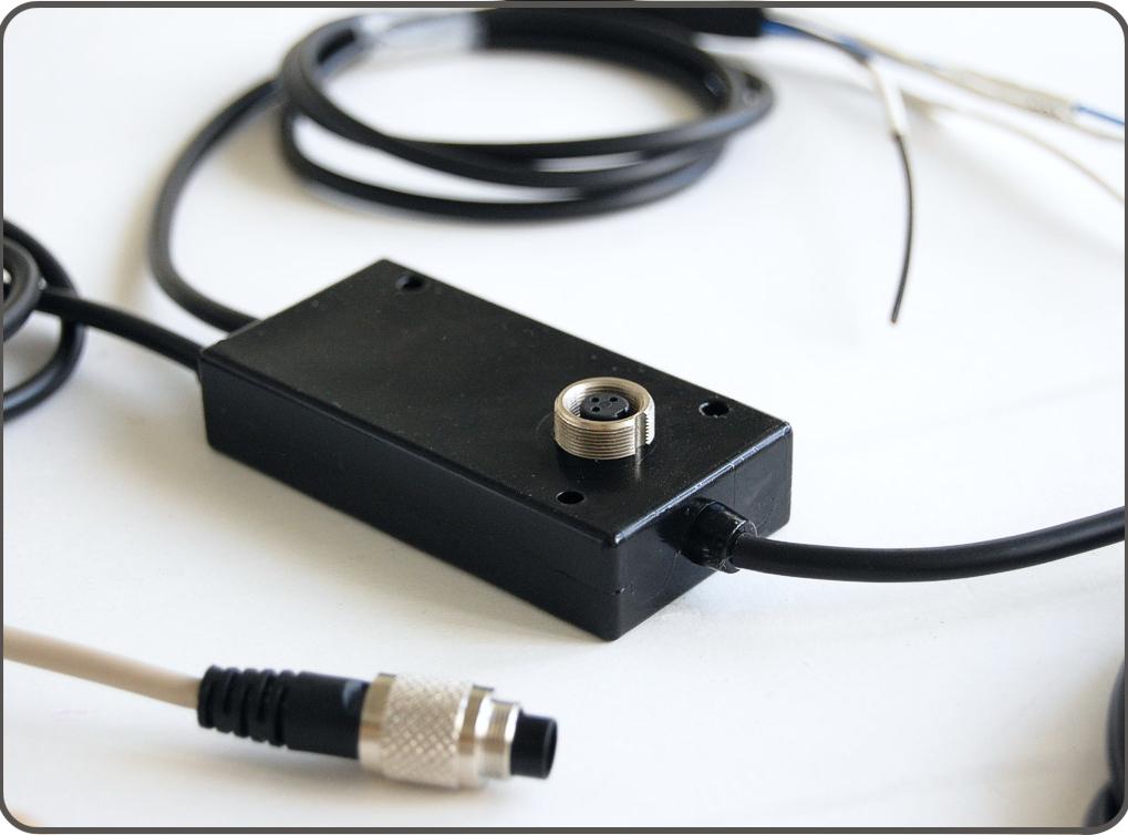
4 0Chapter 1 ECU Bridge: kit, expansions and part numbers Different ECU Bridge can be connected to AIM displays as well as to SmartyCam Kit and part numbers Here follow images and details of ECU Bridge available kits. ECU Bridge CAN/RS232 kit: ECU Bridge with free cables, allows ECU straight connection. The kit includes: ECU Bridge RS232/CAN (1); USB cable for programming (2); CAN/RS232 ECU Bridge kit part number is: X90BGGPI2RMA. ECU Bridge CAN/Kline kit : ECU Bridge with OBDII connector, allows to remote the connection on the vehicle OBDII plug. The kit includes: CAN/K line ECU Bridge (1); USB cable for programming (2); CAN/K Line ECU Bridge kit part number is: X90BGCK12MA 3
5 101.2 ECU Bridge available expansions and related part numbers ECU Bridge sampled not recorded data can be visualised through AIM displays or through SmartyCam, the only on board camera with data overlay. To see data sampled and recorded by SmartyCam an AIM Data Hub is needed to connect the three devices (ECU Bridge, SmartyCam and an AIM display). ECU Bridge expansions part number are: 2 ways Data Hub with 40 cm cable: X08HUB010; 4 ways Data Hub with 150 cm cable: X08HUB150; MyChron3 Dash: X30VDAM01; TGDash: X45VDAM01; Formula Steering Wheel: X07VOLFORM. 4
6 1Chapter 2 Installation, power and connections To install ECU Bridge, its expansions, loggers and display choose a place where the devices are not in contact with heat electromagnetic interference sources like spark plug or coil How to power ECU Bridge ECU Bridge needs a not stabilized 8-18 VDC power sources. It is suggested to power ECU Bridge through the vehicle master switch to save the vehicle battery charge. Use an external power source to power ECU Bridge CAN/RS232 and connect ECU Bridge free cable directly to it. Use the vehicle lighter plug to power ECU bridge CAN/K Line: insert the Bridge lighter plug in the vehicle one Cable labelled GND To correctly power ECU Bridge and for the signal to be stable it is recommended to connect cable labelled GND coming out from ECU Bridge powering harness to thevehicle chassis ground, as highlighted here below. 5
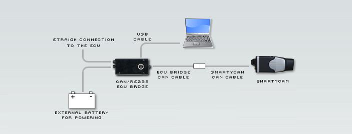
7 62.2 How to connect ECU Bridge. ECU Bridge is to be connected to the different AIM devices but it also needs ECU connection through CAN/RS232 or the K line Connection with AIM devices and with the PC Images here below show how to connect ECU Bridges to SmartyCam and to the PC. Warning: connect ECU Bridge to SmartyCam and to the display OFF. 6
8 7

9 In case a display is wished a un 4 ways Data Hub is needed, as shown here below. 8


10 Connection of CAN/K Line ECU Bridge to the OBDII plug With CAN/K Line ECU Bridge it is possible to receive data out coming from the ECU using the vehicle CAN or K line. It is just sufficient to plug ECU Bridge OBDII connector in the vehicle diagnostic (OBDII) plug and power ECU Bridge using the vehicle lighter plug. Powering the vehicle on, SmartyCam and ECU Bridge will automatically power on. Images here below show the place where OBDII plus is generally placed on the vehicles (top image), a OBDII plug (bottom left) and an example of connection. It is possible that all parameters managed by the ECU are sent on the OBDII plug. Refer to paragraph 3.1 for further information concerning the channels that can be shown on SmartyCam videos. 9

11 Connection of RS232/CAN ECU Bridge to the ECU With RS232/CAN ECU Bridge it is possible to sample data out coming from the vehicle ECU or OBDII plug. To know if the vehicle ECU is supported by ECU Bridge and to know how to connect the vehicle directly to the vehicle OBDII plug refer to the document downloadable from AIM corporate website Download area, ECU connections. Always refer to the ECU user manual for any information concerning pins and cable connections. For straight connection of RS232/CAN ECU Bridge to the ECU, connect the free cables to the ECU pins. Usin the CAN bus connect: ECU Bridge white cable labelled CAN+ to the pin corresponding to ECU CAN+. ECU Bridge blue cable labelled CAN to the pin corresponding to ECU CAN. Using RS232 line connect: ECU Bridge white cable labelled RS232RX to pin RS232TX of the ECU. ECU Bridge blue cable labelled RS232TX to pin RS232RX of the ECU. Refer to the documentation downloadable from AIM corporate website, Download area, ECU Connections for further information concerning the connection of ECU Bridge to the ECU. 10

12 2Chapter 3 Driver, configuration, sampled data visualisation, engaged gear computation and maintenance Once ECU Bridge installation and connection is over it is necessary to configure it using Race Studio Configuration software freely downloadable from Download area /Software. Once software and driver installed connect ECU Bridge to the PC using the USB cable included in the kit. Plug the cable three pins connector in ECU Bridge USB connector shown below, run the software and follow the procedure here explained. Press AIM system manager >> SMC bridge >> New and fill in New configuration panel; Data Logger type : is already set on ECU Bridge; ECU Manufacturer : select the correct vehicle or OBD_II ECU Model select ECU model or OBDII protocol; select the desired measure units and press OK. The system comes back to System Manager window: press SmartyCam Functions setting button top right in the window and select the channels to show. 11
13 113.1 Visualising data sampled by ECU Bridge on SmartyCam video To view data sampled by ECU Bridge on SmartyCam videos it is necessary to set them in the bridge configuration. Pressing SmartyCam functions setting, Set functions to Channels window shows up. It associates each function to the corresponding ECU channels. Available channels changes according to the connection used and to the communication protocol the vehicle can manage. Here below are listed the functions managed and the related channels. Each channel is indicated with 1 or more acronyms. FUNCTIONs Acronyms NOTES RPM RPM Configured by default Speed Average speed computed through the 4 wheel speeds WH_SPD_FL Front left wheel speed Reference speed WH_SPD_FR Front right wheel speed WH_SPD_RL Rear left wheel speed WH_SPD_RR Rear right wheel speed Vel. GPS GPS speed Gears GEAR If missing refer to paragraph 3.2 Water temperature ECT o ENGINET Both acronyms are used Oil temperature OIL_TEMP Other acronyms are also possible Oil pressure OIL_PR_... Other acronyms are also possible Brake pressure BRAKE_PRES S Other acronyms are also possible Throttle opening TPS Throttle opening PPS Acceleration pedal position Brake position BRAKE_SW Other acronyms are also possible Steering wheel position Steer_angle Other acronyms are also possible Once the channels set transmit the configuration to the logger. In case the information concerning the engaged gear is not supplied by the ECU it is possible to compute it as explained in the following paragraph. For any further information concerning ECU Bridge refer to Race Studio Configuration user manual ECU Bridge chapter. Please note: it is suggested to periodically check on Download/software area if new releases of Race Studio 2 software and/or ECU Bridge firmware have been released Gear computation procedure If the vehicle ECU does not provide the information concerning the engaged gear follow this procedure to compute it. For the procedure to be successful carefully follow these instructions. The procedure is to be set via software and starts automatically at ECU Bridge first start up: this is why software configuration is to be made before vehicle power on. Gear calibration is to be correctly performed once.afterwards it is no more necessary. 12


14 Preliminary Information Gear channel calibration is made through rpm and speed channels. These channels are to be both correctly working and configured. In case of protocols with more speed channels configured the system will use the reference speed. AIM suggests to use as reference speed the one of a driving wheel. The computation works also in case of a non driving wheel or a GPS speed but in this case more attention is required to the wheels that should not slip or block during the learning lap Activating the procedure Gear computation is to be set via software with Race Studio 2. With reference to the image here below: run software; press AIM system manager on the left vertical keyboard (1); select SMC Bridge (2); create a new configuration or select an existing one; activate System Configuration (3) layer; enable Calculated gear function and fill in the number of available gears on the vehicle (4); set the reference speed: select GPS speed in case OBDII protocol is being used, as highlighted in the note (5). Once the configuration transmitted to ECU Bridge the system is ready for the learning lap that samples speed and RPM signals needed to perform the gear computation. 13
15 Learning lap During the learning lap follow carefully these instructions: start driving ensuring that the street is clear; engage all gears in sequence; keep each gear engaged for at least 5/6 seconds; drive in a smooth way avoiding sudden accelerations, slips or wheel blocks in braking; RPM should increase gradually; engage all gears and switch of the vehicle or ECU Bridge once the last gear reached; if this is not possible shift the gears each 5/6 seconds engaging the clutch for the minimum time. Warning: absolutely avoid revs while the vehicle is moving and do not drive with the clutch pedal pressed. If required by the vehicle press the accelerator before switching off the engine but only with the vehicle is completely stopped Erasing gear calibration To clear gear calibration use Race Studio 2 software. The procedure is the same performed to set calculated gears but in spite of Calculated highlighted by 4 in the previous image, set None and transmit the configuration to ECU Bridge. To re-compute the engaged gear select again Calculated option and transmit the configuration: ECU Bridge is again ready for a new calibration Configuring the displays To see data sampled by ECU Bridge it is possible to connect it to an AIM display. Available displays are MyChron3 Dash, Formula Steering wheel and TG Dash. Information shown on the different display pages are set through Race Studio 2. Refer to Race Studio Configuration user manual to know how to configure ECU Bridge and/or the displays and to the display user manual for further information concerning their working mode Maintenance The only recommended maintenance for ECU Bridge is a periodical software/firmware update. Updates are downloadable from or Download area firmware/software. To update firmware/software: connect ECU Bridge, SmartyCam and its external GPS; enter click Firmware or Software in Home Page; check if any update has been released; download and run them double clicking on; follow the instruction that appears on the PC monitor. 14
16 3Appendix Technical drawings 15
17 N.rev. / Rev. N. Descrizione / Description Data / date Firma / Sign Contr. da / Ckd. by 5 pins Binder 712 female connector pins Binder 712 female connector Solder termination view CAN K line ECU Bridge pinout OBDII connector CAN K line ECU Bridge 12V plug (2A - 6.3x32mm fuse) "OBDII" 16 pins connector pinout Solder termination view Pin Function CAN+ GND +Vb CAN- +Vbatt Pin Function K line GND L line CAN+ CAN Ohm resistor Collegamento spina 12V Black cable 1000 Ohm resistor Red cable 12V plug Rif. / Ref. Q.tà / Q.ty Materiale / Material N. articolo / Item N. Progettato da / Designed by Contr. da / Ckd. by Approvato da / Approved by Nome file / File name Data / Date Scala / Scale Titolo / Title Pinout ECU Bridge CAN e Linea K Racing Data Power N. disegno / Drawing N. Rev. / Rev. Foglio / Sheet 1 of
18 N.rev. / Rev. N. Descrizione / Description Data / date Firma / Sign Contr. da / Ckd. by 5 pins Binder 712 female connector CAN + RS232 ECU Bridge pinout 120 Ohm resistor between CAN+ and CAN- CAN+RS232 ECU Bridge pins Binder 712 female connector pinout solder termination view Pin Function CAN+ GND +Vb CAN- +Vbatt White RS232RX Black GND Blue RS232TX White CAN+ Blue CAN- Black GND Red +Vbext Rif. / Ref. Q.tà / Q.ty Materiale / Material N. articolo / Item N. Progettato da / Designed by Contr. da / Ckd. by Approvato da / Approved by Nome file / File name Data / Date Scala / Scale Titolo / Title Pinout ECU Bridge - CAN+RS232 Racing Data Power N. disegno / Drawing N. Rev. / Rev. Foglio / Sheet 1 of
ECU Bridge User manual
 User manual Dear customer, Introduction ECU Bridge belongs to the last generation of AIM data acquisition systems for car/bike installations. ECU Bridge is available in two versions: K line/can version
AiM User Manual. ECU Bridge. Release 1.09
 AiM User Manual ECU Bridge Release 1.09 1 Introduction ECU Bridge has been designed and developed by AiM to allow SmartyCam to connect to your vehicle ECU, sample and show the data out coming from it.
Data Hub User manual
 Data Hub Data Hub and ways Release.0 Index Chapter Data Hub: part numbers, optional and installation.... Part numbers.... Optional.... How to install Data Hub... Chapter How to use Data Hub.... Two ways
MARELLI SRA ECU for Formula Renault 2000
 MARELLI SRA ECU for Formula Renault 2000 INTRODUCTION AIM has developed special applications for many of the most popular ECUs; by special applications we mean user-friendly systems which allow to easily
EVO3 Pro/Pista User manual
 EVO Pro/Pista User manual EVO Pro/Pista Release.0 Dear Customer, EVO Pro/Pista belongs to the last generation of AIM data loggers for car/bike installations: a powerful, compact, reliable and expandable
SMARTYCAM User Manual
 SMARTYCAM Dear Customer, SmartyCam, the new camcorder with data overlay, descends from the great AIM experience in developing data acquisition systems, mainly for motorsports applications. SmartyCam allows
Warning: any documentation mentioned in this user manual can be freely downloaded from AIM corporate website at
 USER MANUAL Release. MXL, with all its versions (Strada, Pista, Pro, Pro0) belongs to the new generation of AIM data acquisition systems for car/bike races. Equipped with a beautiful and wide display,
EVO3 Pista pinout "A" GND
 Pinout EVO Pista Release.0 N.rev. / Rev. N. Descrizione / Description Data / date Firma / Sign Contr. da / Ckd. by EVO Pista pinout Logger Status Signalling pins AMP pins AMP pins Binder pins Binder "B"
Suzuki GSX-R K3 Plug&Play kit User Manual
 Suzuki GSX-R K3 Plug&Play kit SUMMARY Preface... 4 Kit description... 5. Part Numbers (see Appendix A )... 7 Plug & Play kits installation... 8. Removing the lateral mirrors and the front and lateral fairings...
WIRING FOR MXL PRO- 05
 CONSTRUCTIVE DOCUMENTATION 0/0/005 WIRING Notes: general-purpose wiring for MXL PRO 05 CAR/BIKE installation Version.00 WIRING FOR MXL PRO- 05 MXL PRO 05 wiring (CAR/BIKES) Logger pinout: 7 pins Deutsch
TECHNICAL DOCUMENTATION 10/10/2005 GAUGE. MyChron 3 LOG BIKE. Introduction. Notes: MyChron 3 LOG BIKE technical documentation Version 1.
 TECHNICAL DOCUMENTATION 10/10/2005 GAUGE Notes: MyChron 3 LOG BIKE technical documentation Version 1.06 MyChron 3 LOG BIKE Figure 1: MyChron 3 LOG BIKE Introduction MyChron 3 LOG BIKE represents the perfect
EVO Dear EVO3 Pista/Pro Owner,
 User Manual EVO3 1.00 Dear EVO3 Pista/Pro Owner, Your EVO3 belongs to the latest generation of AIM loggers for car / bike racing and provides you with a powerful, compact, reliable and expandable data
MXL PRO 05 PLUG & PLAY KIT FOR SUZUKI GSX R YOSHIMURA RACING HARNESS cc
 INSTALLATION DOCUMENTATION 18/11/2005 P&P KIT Installation Manual: MXL PRO 05 P&P kit for SUZUKI GSX R Yoshimura Racing Harness 2004 2005 1000 cc Version 1.00 Suzuki GSX-R Yoshimura Racing Harness 1000cc
SOLO/SOLO DL User manual
 SOLO/SOLO DL User manual Index Index... 1 Introduction... 2 Quick Start Guide... 3 Chapter 1 Included items and optional accessories... 4 1.1 Optional accessories... 6 Chapter 2 Solo at a glance... 7 2.1
AiM User Manual. Channel Expansion connection and configuration for AiM loggers. Release 1.01
 AiM User Manual Channel Expansion connection and configuration for AiM loggers Release 1.01 1 Introduction Channel Expansion is an external expansion module that allows to increase the range of data available
ebox Gold/Extreme for MyChron4 User Manual
 for MyChron4 This user manual is copyright of Aim srl. All procedures here explained can change also substantially. Please check website to get the most recent ones. Aim reserves the right of periodically
Version SmartyCam HD. Rev. 2
 Version 1.01 SmartyCam HD Rev. 2 AVAILABLE VERSIONS SMARTYCAM HD Rev. 2 IN THE BOX (Any microphone cables excluded) SmartyCam HD with 67 or 84 lens, CAN cable or external power cable, USB/AC power adapter,
SmartyManager User manual
 User manual Table of Contents Chapter 1 Installation... 2 1.1 Software installation... 2 1.2 Driver installation... 2 Chapter 2 Quick Guide... 4 2.1 Different working modes... 4 4.2 Configuring SmartyCam
LCU-ONE CAN connected to MXL QM and EVO3 QM User Manual
 LCU-ONE CAN connected to MXL QM and EVO3 QM INDEX Chapter 1 LCU ONE... 2 1.1 Part number... 2 Chapter 2 LCU ONE and Lambda probe mounting... 3 Chapter 3 Connection to MXL EVO3 QM... 5 3.1 LCU-ONE CAN Connection...
AEM ECU EMS V1.19+
 AEM ECU EMS 30-1050 V1.19+ INDEX 1. Introduction Pag. 1 2. AEM EMS 30-1050 Pag. 2 3. RACE STUDIO2 SOFTWARE Pag. 6 INTRODUCTION AIM has developed special applications for many of the most common ECUs: by
INTRODUCTION. Warning: it is strongly recommended to always verify whether the ECU needs specific software settings to export data.
 Link G4 ECU INTRODUCTION AIM has developed special applications for many of the most common ECUs: by special applications we mean user-friendly systems which allow to easily connect your ECU to our hi-tech
Vi-PEC V44 and V88 ECU
 Vi-PEC V44 and V88 ECU Vi-PEC V44 and V88 ECU INTRODUCTION AIM has developed special applications for many of the most common ECUs: by special applications we mean user-friendly systems which allow to
Formula Steering wheel harness from car panel to logger
 N.rev. / Rev. N. escrizione / escription ata / date irma / Sign Contr. da / Ckd. by ormula Steering wheel harness from car panel to logger N.1-4x0.35 mm² cable 5 pins inder 712 Exp. male connector eat
INTRODUCTION. Warning: it is strongly recommended to always verify whether the ECU needs specific software settings to export data.
 Link G4 ECU INTRODUCTION AIM has developed special applications for many of the most common ECUs: by special applications we mean user-friendly systems which allow to easily connect your ECU to our hi-tech
EVO5 Logger USER GUIDE
 Logger USER GUIDE AiM TECH Srl. Via Cavalcanti, 8 20063 Cernusco S/N (MI) Italia Tel. (+39) 02.9290571 Made in Italy www.aim-sportline.com 04 06 08 10 11 12 12 12 14 14 14 14 16 17 18 20 25 28 30 31 34
CH1. Figure 1: M3 LOG Advanced
 TECHNICAL DOCUMENTATION 03/09/2003 GAUGE Notes: M3 LOG Advanced technical documentation, dimensions and pinout. Ver 1.05 M3 LOG Advanced Internal lateral accelerometer CH1 Beacon Speed COM Power CH2 CH3
AiM Infotech. Marelli SRA SRAE SRT small version ECU. Release 1.01
 AiM Infotech Marelli SRA SRAE SRT small version ECU Release 1.01 1 Supported models This tutorial explains how to connect Marelli ECUs to AiM devices. Supported models are: SRA SRAE SRT small version small
Vi-PEC V44 and V88 ECU
 Vi-PEC V44 and V88 ECU INTRODUCTION Vi-PEC V44 and V88 No Adapter ECU AIM has developed special applications for many of the most common ECUs: by special applications we mean user-friendly systems which
AiM Infotech. Hondata KPro4. Release 1.01
 AiM Infotech Hondata KPro4 Release 1.01 1 Supported model This tutorial explains how to connect Hondata ECU to AiM devices. Supported model is: Hondata K-Pro4 to AiM devices. 2 Software setup The ECU comes
DATA ACQUISITION KIT DESCRIPTION INSTALLATION LAYOUT. Wirings connections
 DATA ACQUISITION KIT DESCRIPTION EVO 3 data logger (8 or 13 channels version) Interface Junction Box Aim Infrared transmitter 12 Volts power cable for infrared transmitter Infrared receiver Wirings to
Digital Dash I/O Adapter Configuration
 Digital Dash I/O Adapter Configuration The I/O Adapter adds ten inputs/outputs to the 7 digital dash. These inputs and outputs can then be configured as gauges or switches, and data logged locally through
Race Studio 2. Race Studio 2 Configuration User s manual. Race Studio Configuration: user s manual 1
 Race Studio 2 Race Studio 2 Configuration User s manual Race Studio Configuration: user s manual 1 AIM s.r.l. reserves the right to make changes in the content of this manual without obligation to notify
Solo 2 DL GPS Lap Timer USER GUIDE 1.00
 MANUALE SOLO 2DL.qxp_Layout 1 13/04/18 16:20 Pagina 1 Solo 2 DL GPS Lap Timer USER GUIDE 1.00 Made in Italy www.aim-sportline.com Solo 2 DL GPS Lap Timer 1 Solo 2 DL in a few words 2 What is in the kit?
Dear MyChron Light TG Owner
 Dear Owner Your new Instrument is the evolution of MyChron Light MCL. This new instrument merges all functionalities and values of MyChron Light MCL with the new graphic display and gives you a lot of
Kart Price list Ver July 2018
 Index MyChron5 MyChron5 2T MyChron Expansion MyChron5 Steering Wheel MyChron Oval Steering Wheel LCU-One CAN Data Hub Tire temperature sensors kit Accelerator/brake pedal position sensor Other sensors
AiM SmartyCam GP HD Rev. 2.1
 17.1 67 50.1 26.5 26.5 37.2 65.2 3.2 102.5 7 70 3.5 O24 26.6 1/6 Technical characteristics Video format Display resolution Lens H.264 1280 x 720 pixels @ 30 fps 2.4" 240 x 320 pixels Telecentric with 6
Memory Module. GS-Dash Formula Steering Wheel 3. GPS Module Lambda Channel Expansion/TC Hub Remote buttons interface
 Page 1 01.26.28 Apr, 12 2018 Added remote display management 01.26.22 01.26.28 01.26.28 35.58 25.47 40.61 70.03 Memory Module GS-Dash Formula Steering Wheel 3 01.26.25 Jan 11 2018 Fixed bug when e Start
LCU ONE Analog User manual
 LCU ONE Analog User manual INDICE Chapter 1 LCU-ONE Description...2 Chapter 2 LCU-ONE and Lambda probe mounting...3 Chapter 3 Configuration...4 3.1 LCU-ONE Analog standard configuration...4 3.2 LCU-ONE
Haltech IQ3 Street Dash Guide
 Haltech IQ3 Street Dash Guide Thank you for purchasing a Haltech IQ3 Street dash. This guide provides information on the installation and basic use of your dash. Your dash is preconfigured by Haltech with
ADR. - Configuration and Functionality USER MANUAL
 ADR - Configuration and Functionality USER MANUAL Installation Contents Installation... 3 Dimensions... 3 Configuration... 4 Connection to the ADR... 4 Password Support... 5 Device Configuration... 5 Device
MXL QM/EVO3QM User Manual
 MXL QM/EVO3QM Dear MXL / EVO3 QM Owner AIM has created technical instruments specifically for the exciting world of jr. dragsters: AIM MyChron3 660 is considered today the most powerful data logger designed
Dear MyChron 3 Owner
 AiM MyChron3 Basic Dear MyChron 3 Owner The MyChron 3 represents the new generation of Aim data acquisition systems that provides the karter with a sophisticated and easy to use display normally reserved
Car/bike price list Ver December 2018
 Car/bike price list Index LCD/TFT DASH LOGGERS CAMERAS MXL2 1 SmartyCam HD Rev. 2.1 15 MXm 1 SmartyCam GP HD Rev. 2.2 18 MXS 1.2 MXP MXG 1.2 2 3 4 EXPANSIONS Channel Expansion Data Hub 21 21 TFT DASHES
This manual is for the installation and operation of the DASH2 PRO unit, for detailed instructions on the configuration software please refer to the
 This manual is for the installation and operation of the DASH2 PRO unit, for detailed instructions on the configuration software please refer to the PC based help system. Where relevant a web address for
Table of Contents. Table of Contents
 Table of Contents Table of Contents Introduction... 3 Installing a V Series Data Logger... 5 Getting acquainted with your V Series Logger System... 5 The Data Loggers... 5 The System Components... 6 Planning
AiM SmartyCam HD Rev. 2.1
 87 3.4 31.2 18.4 63 SMARTYCAM HD rev. 2.1 made in Italy SMARTYCAM HD rev. 2.1 ext GPS 1/6 Technical characteristics Video format Display resolution Lens H.264 1280 x 720 pixels @ 30 fps 128 x 128 pixels
MOTORSPORT RACING GUIDE
 2011 MOTORSPORT RACING GUIDE AIM Srl Via Cavalcanti, 8 20063 Cernusco S/N (Mi) Italia Tel. (+39) 02-9290571 Fax (+39) 02-92118024 www.aim-sportline.com memotec GmbH Bauwaldstrasse 1 75031 Eppingen Germany
Marelli SRA ECU Technical documentation Release 1.03 INTRODUCTION logger Race Studio 2
 MARELLI SRA ECU INTRODUCTION AIM has developed special applications for many of the most popular ECUs; by special applications we mean user-friendly systems which allow to easily connect your ECU to our
AiM Infotech. MoTec CAN Custom Data Set1. Release 1.01
 AiM Infotech MoTec CAN Custom Data Set1 Release 1.01 This tutorial explains how to connect MoTec and AiM devices. 1 Software Setup MoTec devices need to be set up via MoTec ECU Manager software. Run it
AiM Racing Products 2015
 CMV ADVERTISING AiM Racing Products 2015 AiM SRL Via Cavalcanti, 8 20063 Cernusco S/N (Mi) Italy P. (+39) 02-9290571 F. (+39) 02-92118024 Made in Italy www.aim-sportline.com AiM Racing Products 2015 AiM
MyChron Light TG User Manual
 AiM MyChron light TG MyChron Light TG, the new AIM lap timer, is the evolution of the well known MyChron Light MCL. This new logger merges all functionalities and good qualities of its forefather with
CAN DISPLAY DASH & LOGGER SYSTEM QUICK START GUIDE
 CAN DISPLAY DASH & LOGGER SYSTEM QUICK START GUIDE AEM Performance Electronics 2205 126th Street Unit A, Hawthorne, CA 90250 Phone: (310) 484-2322 Fax: (310) 484-0152 http://www.aemelectronics.com Instruction
User Manual. LCU ONE Analog
 LCU ONE Analog INDICE Chapter 1 LCU-ONE Description...2 Chapter 2 LCU-ONE and Lambda probe mounting...3 Chapter 3 Configuration...4 3.1 Preliminary operation... 5 3.2 Configuring Lambda controller... 5
Race Keeper Pectel ECU Data Module User Guide v1.1 January 2012
 Race Keeper Pectel ECU Data Module User Guide v1.1 January 2012 Trivinci delivers user guides exclusively in soft format Trivinci Systems, LLC Race Keeper Pectel ECU Data Module User Guide v1.1, January
User Guide. Subaru Turbo (North American Models)
") User Guide Subaru Turbo (North American Models) Page 2 Table of Contents Product Introduction 4 Supported Vehicle List 4 In-Box Contents 5 What Is A Map? 7 AccessPORT Installation 8 Pre-Installation 8
User Guide Subaru Turbo (North American Models) Page 2 Table of Contents Product Introduction 4 Supported Vehicle List 4 In-Box Contents 5 What Is A Map? 7 AccessPORT Installation 8 Pre-Installation 8
Trouble Shooting Leveling Control Box Electric Jacks. Touch Pad LED Probable Cause Solution
 Trouble Shooting Leveling Control Box 140-1224 Electric Jacks Copyright Power Gear Issued: January 2013 #82-L0524, Rev. OA Touch Pad LED Probable Cause Solution 1. On/Off LED will not light 2. Wait LED
AX22 Performance Computer
 AX22 Performance Computer Built in high accuracy 5Hz GPS Digital accelerometers Compact flash memory Lap beacon input Serial input from ECU/OBDii Very high accuracy measurements of acceleration timings
12.3 Pro Dash Quick Start Guide
 12.3 Pro Dash Quick Start Guide 553-111 CONTENTS: Package Contents... 3 Mounting... 3 Connections... 4 Main Connector... 4 CAN Extension Harness... 6 USB... 7 GPS Antenna... 7 Cleaning... 7 Touchscreen
Features: Contents: If you are missing any of the above components please contact Racepak at
 -------------------------------------------------------------------------------------------- 250-DS-UDX -------------------------------------------------------------------------------------------- Features:
Fixed bug on Digital output priority handling. Fixed bug in volume sensors with gallons unit measure. Memory Module GPS Module
 Page 1 01.26.46 Dec, 5 2018 Added management of Shift Light Module No changes 01.26.38 Oct, 5 2018 Added possibility to force channels in Online Fixed bug on Digital output priority handling No changes
Quick Start Guide. Data Logger TrueLog100
 Quick Start Guide Data Logger TrueLog100 Antenna Port 3 Port 4 1 1 1 1 Port 1 1 Port 2 RSSI PC Measure SIM + Battery + Solar Power Supply Figure 1: Top view of the data logger TrueLog100. All ports and
MyChron5 - MyChron5 2T USER GUIDE
 MANUALE IMPAGINATO.qxp_Layout 1 25/11/15 16:03 Pagina 1 MyChron5 - MyChron5 2T USER GUIDE AiM Srl. Via Cavalcanti, 8 263 Cernusco S/N (MI) Italia Tel. (+39) 02.9290571 Made in Italy www.aim-sportline.com
OBDII J1708/J1587 Simulator
 1 Features: Support the total 8 protocols., Customer can choose any 2 protocols or any 5 protocols or all 8 protocols in different cost 1. ISO14230-4 (KWP2000) Fast Init 2. ISO14230-4 (KWP2000) Baud 5
/8H Infinity Hardware Specification STOP! THIS PRODUCT HAS LEGAL RESTRICTIONS. READ THIS BEFORE INSTALLING/USING!
 Instruction Manual 30-7106/8H Infinity Hardware Specification STOP! THIS PRODUCT HAS LEGAL RESTRICTIONS. READ THIS BEFORE INSTALLING/USING! THIS PRODUCT MAY BE USED SOLELY ON VEHICLES USED IN SANCTIONED
VSI-2534 User Manual
 VSI-2534 User Manual Version 2.2 April 2011 Foreword This document describes AutoEnginuity (DG) VSI-2534, and SAE J2534 Pass-Thru device with its primary purpose to program automotive ECUs (Electronic
An ISO 9001:2008 Registered Company
 An ISO 9001:2008 Registered Company Upfitter Interface Module The following list represents firmware v4.30 A-UIM4-506-A 2011-2016 Ford F250-550 B-UIM4-506-A 2017 F250-F550 A-UIM4-751-A 2013-2017 1500-5500
Hyper Stimulator Set Up Instructions
 Hyper Stimulator Set Up Instructions If you are setting up your Hyper Stimulator for the first time, these guidelines will help you ensure your Hyper Stimulator is unpacked and connected in the correct
Table of Contents MOTOROLA SEQUENTIAL MOTOROLA BACKWARD APPENDIX C. PIN CONNECTIONS SERIAL DATA OUT CONNECTOR...
 Table of Contents INTRODUCTION... 3 PARTS SUPPLIED... 3 BEFORE YOU BEGIN... 3 DESCRIPTION OF OPERATION... 4 RT MESSAGE... 4 CAN ID LENGTH... 4 CAN ID... 5 FILTER LOCATION... 5 FILTER VALUE... 5 START BIT...
PCM4-CAM NTV-KIT750. Overview
 3950 NW 120 th Ave, Coral Springs, FL 33065 TEL 561-955-9770 FAX 561-955-9760 www.nav-tv.com info@nav-tv.com PCM4-CAM NTV-KIT750 Overview The PCM4-CAM Kit interfaces a backup camera input (with active
Options. Parts List. Optional Expansion Hub Optional Ignition Module Optional Memory Card
 Options Optional Expansion Hub Optional Ignition Module Optional Memory Card View boost, speed, and gear on the LCD Display. View the ignition changes on the LCD Display. Log and store map data. Card storage
CAN Switch Board (CSB)
") CAN Switch Board (CSB) The Cosworth CSB is a fully customised CAN Switch Board designed to be light and compact enough to fit onto a steering wheel. The CSB allows complicated steering wheel and connector
CAN Switch Board (CSB) The Cosworth CSB is a fully customised CAN Switch Board designed to be light and compact enough to fit onto a steering wheel. The CSB allows complicated steering wheel and connector
Chrome USER MANUAL. Version 1.1
 Chrome USER MANUAL Version 1.1 Summary INTRODUCTION... 3 BEFORE YOU START... 4 BOX CONTENT... 5 CHROME INSTALLATION... 6 GPS INSTALLATION... 7 CHROME INPUTS... 8 USE OF BUTTONS TO NAVIGATE THROUGH THE
Family Software 3164 Surrey Lane Aston, PA (610)
") Family Software 3164 Surrey Lane Aston, PA 19014 (610) 497-5561 'Drag Racing Computers and Software' - www.ifamilysoftware.com DataMaster Sportsman Computer- Instructions Introduction Congratulations on
Family Software 3164 Surrey Lane Aston, PA 19014 (610) 497-5561 'Drag Racing Computers and Software' - www.ifamilysoftware.com DataMaster Sportsman Computer- Instructions Introduction Congratulations on
SDL User s Manual. Contents. Introduction... 1 Overview Installation Sport Dash Manager Software... 23
 MoTeC SDL User s Manual Contents Introduction... 1 Overview... 2 Display...2 Alarms...5 Data Logging...5 Other Functions...7 Measurement Inputs...8 Auxiliary Outputs...12 Communications Overview...13 ECU
DAILY VEHICLE EXPANSION MODULE
 DAILY VEHICLE MY 2009 RANGE BODYBUILDERS INSTRUCTIONS EXPANSION MODULE L I G H T R A N G E ISSUE 2010 Publication Edited by: IVECO S.p.A. Technical Application Strada delle Cascinette, 424/34 10156 Torino
TECHNICAL DATASHEET #TDAX050000K CAN
 This cost-effective, compact and robust CAN display shows machine, engine and transmission operating parameters and service codes. Enhanced operating information made available to a vehicle operator improves
TM LOCKPICK C8 INSTALLATION OPTIONS COPYRIGHT 2011 COASTAL ELECTRONIC TECHNOLOGIES, INC. UNPLUG ORIGINAL RADIO CONNECTORS THEN PLUG IN HERE
 TM LOCKPICK C8 INSTALLATION OPTIONS COPYRIGHT 2011 COASTAL ELECTRONIC TECHNOLOGIES, INC. FACTORY CONNECTORS INCLUDED UNPLUG ORIGINAL RADIO CONNECTORS THEN PLUG IN HERE PLUG AND PLAY NO OTHER CONNECTIONS
Operator s Manual. Morbark Integrated Control System Woodhog Series Model 2600
 Operator s Manual Morbark Integrated Control System Woodhog Series Model 2600 Contents Introduction 4 Parts Identification 6 Display Module Display Pages 9 Main Page 11 Engine Information Page 12 Hydraulic
V5 Build 100 SOFTWARE AND FIRMWARE UPDATES
 V5 Build 100 SOFTWARE AND FIRMWARE UPDATES Who should update: It is recommended that any user update to this latest version of software and firmware. There are improvements to laptop communication speeds
Manual# Installation Manual. 200E Series. DCU 210E/208E Engine Panel RP 210E/220E Remote Panel
 Manual# 1006495 Installation Manual 200E Series DCU 210E/208E Engine Panel RP 210E/220E Remote Panel Installation Manual for the Marine Pro 200E Series ~~~ DCU 210E/208E Diesel Engine Control Unit RP 210E/220E
Orion Jr. Purchasing Guide Rev. 1.2
 www.orionbms.com Orion Jr. Purchasing Guide Rev. 1.2 The Orion Jr. BMS is a low cost battery management system designed to manage low voltage lithium ion battery packs up to 48V nominal. The Orion Jr.
GILLIG ELECTRIC BUS Diagnostic Software User Guide & Troubleshooting Guide 8A Rev C Last Revised: 3/23/2017
 GILLIG ELECTRIC BUS Diagnostic Software User Guide & Troubleshooting Guide 8A003378 Rev C Last Revised: 3/23/2017 Table of Contents Section 1: Introduction... 2 Connector Definitions... 2 Location of Connectors...
AX-AM-AU94. Audi Q5 (8R) (with Concert Radio) HDMI and Camera Interface
 (with Concert Radio) HDMI and Camera Interface") AX-AM-AU94 INSTALLATION INSTRUCTIONS INTERFACE COMPONENTS AX-AM-AU94 interface AX-AM-AU94 harness 10-pin harness with RCA jacks 10-pin T harness 20-pin T harness Audi Q5 (8R) (with Concert Radio) HDMI
AX-AM-AU94 INSTALLATION INSTRUCTIONS INTERFACE COMPONENTS AX-AM-AU94 interface AX-AM-AU94 harness 10-pin harness with RCA jacks 10-pin T harness 20-pin T harness Audi Q5 (8R) (with Concert Radio) HDMI
Quick Reference Card. Setting up the FmX Integrated Display with the Autopilot System
 Setting up the FmX Integrated Display with the Autopilot System Quick Reference Card CONNECTING THE SYSTEM Once the Autopilot system has been professionally installed, add the FmX integrated display as
GMNAV1 Advent Integrated Navigation
 GMNAV1 Advent Integrated Navigation This interface is designed to integrate Navigation into select Buick and Chevrolet Systems. INSTALLATION MANUAL What s in the Box The following items are supplied with
CONCEPT P/N: AX Concept TECHNICAL DATASHEET #TDAX Analog Input CAN Controller CAN (SAE J1939 or CANopen ) with Electronic Assistant
 with Electronic Assistant") Concept TECHNICAL DATASHEET #TDAX030400 6 Analog Input CAN Controller CAN (SAE J1939 or CANopen ) with Electronic Assistant Features: 6 analog inputs (0-5V, 0-10V, 0-20mA, 4-20mA, Resistance, PWM, Digital,
Concept TECHNICAL DATASHEET #TDAX030400 6 Analog Input CAN Controller CAN (SAE J1939 or CANopen ) with Electronic Assistant Features: 6 analog inputs (0-5V, 0-10V, 0-20mA, 4-20mA, Resistance, PWM, Digital,
Pre-LCI F Series NBT (EVO) Retrofit Adapter
 Retrofit Adapter") Pre-LCI F Series NBT (EVO) Retrofit Adapter (with MOST bus support) Rev 1.5 BEFORE YOU START READ THE COMPLETE INSTRUCTIONS CAREFULLY BEFORE BEGINNING THE INSTALLATION IF YOU HAVE ANY QUESTIONS ABOUT THE
Pre-LCI F Series NBT (EVO) Retrofit Adapter (with MOST bus support) Rev 1.5 BEFORE YOU START READ THE COMPLETE INSTRUCTIONS CAREFULLY BEFORE BEGINNING THE INSTALLATION IF YOU HAVE ANY QUESTIONS ABOUT THE
APVLR12. Rear View Camera Input and Video In Motion.
 APVLR12 Rear View Camera Input and Video In Motion www.connects2.com ABOUT THIS PRODUCT... APVLR12 Reversing Camera Add-On and Video in Motion Interface for Land Rover touch screen navigation version 3
Jaguar F-TYPE CAM 16. Dual Camera interface for select 16+ Jaguar vehicles NTV-KIT746 BHM 05/31/16 NTV-DOC259
 3950 NW 120 th Ave, Coral Springs, FL 33065 TEL 561-955-9770 FAX 561-955-9760 Jaguar F-TYPE CAM 16 Dual Camera interface for select 16+ Jaguar vehicles NTV-KIT746 BHM Overview Jaguar F-TYPE CAM 16 interfaces
MTX-D Ethanol Content and Fuel Temperature Gauge User Manual
 MTX-D Ethanol Content and Fuel Temperature Gauge User Manual P/N 3912 kit does not include flex fuel sensor. The ECF-1 is compatible with GM P/Ns 13577429 and 13577379 1. Installation... 2 1.1 Gauge Mounting...
PowerView. Hub. by LUXAFLEX WINDOW FASHIONs
 PowerView Hub by LUXAFLEX WINDOW FASHIONs quick start guide Table of Contents Kit Contents...3 Connections... 4 Home Automation Integration... 10 Troubleshooting... 11 The PowerView Hub interfaces with
X-431 Volkswagen Diagnosis. Table of Contents INTRODUCTION...1
 Table of Contents INTRODUCTION...1 FEATURES...1 Advanced...1 Open...1 Integrative...1 Flexible...1 HARDWARE CONFIGURATION...2 PORTS AND INDICATORS...3 PRINTER OPERATION...4 Mounting Paper...4 Printing
!"#$%&'()&'*+#,,-$#*+&(.,./0&)-12,%3
&'*+#,,-$#*+&(.,./0&)-12,%3") !"#$%&'()&'*+#,,-$#*+&(.,./0&)-12,%3 Cosworth's Omega ICD is a widescreen TFT colour display coupled with a fully featured data logger in a single attractive aluminium housing. Using a widescreen 6.2"
!"#$%&'()&'*+#,,-$#*+&(.,./0&)-12,%3 Cosworth's Omega ICD is a widescreen TFT colour display coupled with a fully featured data logger in a single attractive aluminium housing. Using a widescreen 6.2"
Jaguar F-TYPE CAM Dual Camera interface for select 14+ Jaguar vehicles NTV-KIT589
 3950 NW 120 th Ave, Coral Springs, FL 33065 TEL 561-955-9770 FAX 561-955-9760 Jaguar F-TYPE CAM Dual Camera interface for select 14+ Jaguar vehicles NTV-KIT589 BHM Overview Jaguar F-TYPE CAM interfaces
VANTAGE CL1. Installation and use of the CL1 Karting Data Kit
 Installation and use of the CL1 Karting Data Kit Table of Contents What s in the box 3 Items needed for installation 4 CL1 registration 5 D3 app install 6 Battery installation 7 Mounting the CL1 data box
Electrical Data. Ethernet. LIN Bus. Internal Sensors. Part Number
 Cosworth's Omega ICD is a widescreen TFT colour display coupled with a fully featured data logger in a single attractive aluminium housing. Using a widescreen 6.2" TFT, coupled with dedicated graphic processors,
C2-MMI2G-x. Compatible with Audi MMI 2G navigation systems
 c.logic Interface C2-MMI2G-x Compatible with Audi MMI 2G navigation systems Product features Full plug and play multimedia interface 2 AV-inputs with separate IR-control-channels Integrated into vehicle
FDS3NAV2. For Ford Vehicles Equipped With SYNC3. Installation Instructions. Calibration and Setup Guide. Page 1 of 14
 FDS3NAV2 For Ford Vehicles Equipped With SYNC3 Installation Instructions Calibration and Setup Guide Page 1 of 14 Please read this manual thoroughly before installation. This manual illustrates a typical
Introduction of Au SAE J1939 Simulator Gen II 1.00A and 2.00A
 Introduction of Au SAE J1939 Simulator Gen II 1.00A and 2.00A Au SAE J1939 Simulator Gen II (Figure 1), a family of well designed devices, is capable of simulating majority of SAE J1939 signals on a SAE