Setup Instructions English
|
|
|
- Frederica Randall
- 6 years ago
- Views:
Transcription

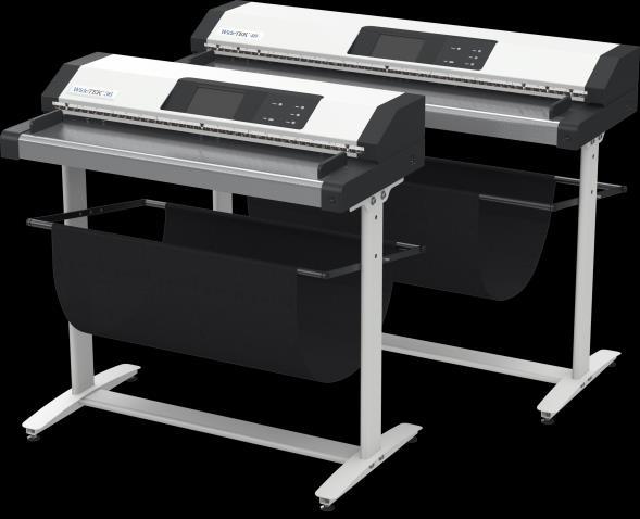

1 WideTEK 36/44/48 Setup Instructions English 01/2017
2 Contents Information about the Instructions and the Manufacturer... 4 Keep Instructions with the Scanner... 4 Design Features in Text... 5 Design Features in Pictures... 5 Associated Documents... 6 Copyright... 6 Contact Data of the Manufacturer in Germany... 6 Technical Support... 6 Contact Data of the Manufacturer in the U.S Safety... 7 Intended Use... 7 Basic Safety Information... 7 Avoiding Property Damage and Malfunctions... 8 Responsibility of the Owner... 9 Staff Qualifications... 9 Design Features of Warning Notices Formatting of Information Regarding Property Damage Description Purpose and Function WideTEK 36 Overview WideTEK 44 Overview WideTEK 48 Overview Rear View Setup Menu Overview Screen Rating Plate Prepare for Setup Connect the Power Supply Establish the Network Connection Positioning the Scanner on the Optional Floor Stand... 20
3 Connect the Optional Foot Switch Connect the Optional Monitor Connect the Optional Touchscreen Switch On the Scanner Switch Off the Scanner Perform Setup Change the Menu Language Activate the Setup Menu Perform White Balance Assign the IP Address Modify User Settings Set the Time and Date Perform Test Suite Touchscreen Test Technical Specifications WideTEK 36/44/48 Scanner Specification Ambient Conditions Electrical Data Document specifications Dimensions and Weight WideTEK Dimensions and Weight WideTEK 44/
4 Information about the Instructions and the Manufacturer Information about the Instructions and the Manufacturer These instructions show you how to safely prepare and perform the setup for the wide format scanners WideTEK 36/44/48. The WideTEK 36/44/48 scanners are hereinafter referred to as "Scanner". In these instructions, the start button is called "power button". Keep Instructions with the Scanner These instructions are a part of the scanner. Please always store these instructions together with the scanner. Ensure that the instructions are available for the user. Enclose the instructions when you sell the scanner or transfer it in any other way. 4

5 Information about the Instructions and the Manufacturer Design Features in Text Many text passages in these instructions have been formatted to indicate specific elements, as illustrated below: Normal text BUTTONS OF THE SCREEN PAGE "Menu names" Action steps Enumeration of the first level Cross-references Tips contain additional information, such as special information to prepare for and perform the setup. Design Features in Pictures Where a reference is made to elements in a legend or in the text, these are marked with a number (1). 5
6 Information about the Instructions and the Manufacturer Associated Documents In addition to these instructions, other documents associated with the operation of the scanner include: Unpacking and Repacking Instructions Legal Information (Declarations of Conformity, FCC Declaration, Safety & EMI Certificates, RoHS etc.). Copyright These instructions contains information that is subject to copyright. These instructions may not be reproduced in any form, printed, filmed, edited, copied or distributed, in whole or in part, without prior written permission from Image Access GmbH. Image Access GmbH 2017 All rights reserved. Contact Data of the Manufacturer in Germany Image Access GmbH Hatzfelderstraße Wuppertal Phone: Internet address: Technical Support Image Access technical support can be reached at the address: Contact Data of the Manufacturer in the U.S. Image Access LP 745 Duffy Drive, Unit D Crystal Lake IL Phone: support@imageaccess.us Internet address: 6
7 Safety Safety Intended Use The scanner is used for scanning images and documents. The documents must comply with the characteristics described in the technical specifications. The scanner is designed for use in enclosed spaces in the commercial sector. Intended use also includes observing and following all information provided in these instructions, especially the safety instructions. Any other use is considered to be improper and will void the warranty and liability claims. Ambient Conditions Ensure that the scanner is used exclusively under the following environmental conditions: Ambient temperature during operation: +5 C to +40 C Storage temperature: 0 C to +60 C Relative humidity: 20 to 80%, non-condensing Ensure that the scanner is not exposed to direct sunlight. Basic Safety Information Avoid Injury or Death by Electric Shock Never open the housing of the scanner. Do not expose the scanner to dripping or splashing water and do not place any vessel filled with liquid on the scanner. Penetrating liquid can damage the scanner. Do not insert objects through existing slots or openings into the interior of the scanner. 7
8 Safety Only connect the scanner with the plug of the supplied AC adapter to a professionally installed and grounded outlet. Do not use the AC adapter if the power supply's housing or the cable are damaged. In this case, replace the power supply with a power supply of the same type. Do not use the scanner if it is visibly damaged. In this case, unplug the power cord from the wall outlet. Contact Image Access technical support, see section Technical Support starting at page 6. Avoid Burns Do not cover the existing openings in the scanner housing. They serve to ventilate. Covering the openings could cause overheating. Do not place the scanner in front of air conditioning units, which produce high heat. Avoid Fractures, Contusions and Bruises Incorrect installation of the cables can cause tripping. Lay the connecting cables so that no one can trip over them. The scanner weighs between 41 and 53 kg, depending on the model. Only carry the scanner with a second person. Place the scanner only on a stable, level and vibration-free surface that has sufficient strength for the weight of the scanner. Avoiding Property Damage and Malfunctions Ensure adequate ventilation to comply with the environmental conditions. Do not place the scanner in the vicinity of devices that emit strong electromagnetic radiation. Always place the scanner on a suitable, stable table or the optional floor stand. Do not lean on the scanner. Ensure that the thickness of the material to be scanned does not exceed 2,5 mm. Do not use any cleaning agents containing abrasive additives, solvents or acids. Use a damp microfiber cloth. Operate the touchscreen only with your finger. Other objects can damage the touchscreen. 8
9 Safety Responsibility of the Owner The scanner owner must ensure that only qualified personnel carry out the setup of the scanner. Staff Qualifications The staff that carries out the setup of the scanner must have knowledge in installing, connecting and putting computer accessories into operation. 9
10 Safety Design Features of Warning Notices In these instructions, the following warning information can be found: WARNING Notices with the word WARNING warn about a dangerous situation that could lead to death or serious injuries. CAUTION Notices with the word CAUTION warn about a situation that could lead to light or medium-scale injuries. The following symbols are used in the warnings: Symbol Explanation Danger from electrical shock General danger symbol Formatting of Information Regarding Property Damage ATTENTION! These notices warn of situations that can lead to property damage. 10
11 Description Description Purpose and Function The scanner is used for scanning images and documents. It is designed for use in enclosed spaces in the commercial sector. Intended use also includes observing and following all instructions in these instructions, especially the safety instructions. Any other use is considered to be improper and will void the warranty and liability claims. WideTEK 36 Overview No. Name 1 Document transport 2 Touchscreen 3 Power button 4 Main switch 5 Transport guides 11
12 Description WideTEK 44 Overview No. Name 1 Document transport 2 Touchscreen 3 Power button 4 Main switch 5 Transport guides The WideTEK 44 scanner can be extended to a WideTEK 48 by purchasing a software option. 12

13 Description WideTEK 48 Overview No. Name 1 Document transport 2 Touchscreen 3 Power button 4 Main switch 5 Transport guides 13

14 Description Rear View The following diagram shows the rear view of the WideTEK 36 model. No. Name 1 USB connector 2 Network connector 3 HDMI connector 4 24 V DC connector for external power supply 5 Foot switch connector 6 Recovery key connector 14

15 Description Setup Menu Overview Screen No. Name 1 Buttons and parameters 2 Menu name 3 Display the online help 1 4 Button to leave the setup menu to the start screen 5 Button to drive the document forward in the scanner 6 Button to drive the document backward in the scanner (rewind). 7 Firmware version 8 IP address 9 Serial number 1 The display of the online help is only available when a second touchscreen is connected to the scanner. 15
16 Description Rating Plate The rating plate is attached to the back of the scanner. The following figure shows the WideTEK 36 rating plate. 16

17 Description The following figure shows the WideTEK 44 rating plate. 17
18 Description The following figure shows the WideTEK 48 rating plate. 18
19 Prepare for Setup Prepare for Setup Connect the Power Supply WARNING Risk of electric shock due to incorrect connection. Ensure that the power receptacle intended for the connection is properly grounded. Ensure that the power receptacle intended for the connection of the scanner is properly fused. CAUTION Incorrect laying of the connection cables can cause tripping. Fractures, contusions and bruises can be the result. Place the connecting cables so that nobody can trip over them. To connect the power supply, proceed as follows: Make sure that the main switch of the scanner is switched off (0 position). Use only the AC adapter and power cord supplied. Ensure the power cord is not damaged. Connect the connector from the power supply to the associated 24 V DC connector on the back of the scanner. If not already done, connect the supplied power cable to the associated connector on the power supply. Connect the power plug of the power supply to a power receptacle of the correct voltage ( VAC). Establish the Network Connection CAUTION Incorrect laying of the connection cables can cause tripping. Fractures, contusions and bruises can be the result. Place the connecting cables so that nobody can trip over them. 19
20 Prepare for Setup To establish the network connection, proceed as follows: Connect one plug of the enclosed network cable to the network connector socket on the back of the scanner. Connect the second plug to the network socket of an existing network. Positioning the Scanner on the Optional Floor Stand CAUTION The scanner weighs between 41 kg and 53 kg, depending on the model. Only carry the scanner with a second person. Ensure that the scanner is secured so that it does not fall over. To position the scanner on the optional floor stand, proceed as follows: Assemble the floor stand according to the floor stand assembly instructions. Position the scanner on the floor stand as described in the accompanying floor stand assembly instructions. Connect the Optional Foot Switch CAUTION Incorrect laying of the connection cables can cause tripping. Fractures, contusions and bruises can be the result. Place the connecting cables so that nobody can trip over them. To connect the optional foot switch, proceed as follows: Connect the plug of the foot switch to the connector socket for the foot switch, located on the back of the scanner. 20
21 Connect the Optional Monitor CAUTION Prepare for Setup Incorrect laying of the connection cables can cause tripping. Fractures, contusions and bruises can be the result. Place the connecting cables so that nobody can trip over them. To connect the optional monitor, proceed as follows: Connect the HDMI connector plug of the monitor to the HDMI connector socket, located on the back of the scanner. 21
22 Prepare for Setup Connect the Optional Touchscreen CAUTION Incorrect laying of the connection cables can cause tripping. Fractures, contusions and bruises can be the result. Place the connecting cables so that nobody can trip over them. To connect the optional touchscreen, proceed as follows: Connect the HDMI connector plug of the touchscreen to the HDMI connector socket, located on the back of the scanner. Connect the USB connector plug of the touchscreen to the USB connector socket, located on the back of the scanner. 22
23 Switch On the Scanner To switch on the scanner, proceed as follows: Press the MAIN SWITCH (1) to the "I" position. The following diagram shows the scanner model WideTEK 36. Prepare for Setup The scanner is in standby mode. The power switch is illuminated in red. 23
24 Prepare for Setup To start the scanner from standby mode, proceed as follows: Press the red illuminated power button. The power button lights up in blue. The scanner performs a system test. After a short wait, the "Start screen" is displayed in English. 24
25 Prepare for Setup Switch Off the Scanner To switch the scanner to standby mode after performing the setup, proceed as follows: On the "Start screen" screen tap on SHUTDOWN (1). Confirm with YES. The scanner shuts down. This process can take up to 40 seconds. The power button lights up red. The scanner is in standby mode. 25
26 Prepare for Setup Alternatively, switch the scanner into the standby mode as follows: Press the blue illuminated power button and hold it for six seconds. The scanner shuts down. This process can take up to 40 seconds. The power button lights up red. The scanner is in standby mode. To switch off the scanner for longer periods, proceed as follows: Make sure that the scanner is in standby mode. The power button is illuminated in red. Press the MAIN SWITCH (1) in the "0" position. The following diagram shows the scanner model WideTEK
 button.")
27 Perform Setup Change the Menu Language To change the menu language, proceed as follows: Tap the LANGUAGE (1) button. 27

28 A window for selecting the language appears. To display more languages, slide the scroll bar (1) downward. Tap the desired language. The window for selecting the language is closed. The "Start screen" is displayed. 28
29 Activate the Setup Menu To activate the setup menu, you have to log in on the scanner. Proceed as follows: Tap the GEAR SYMBOL (1). 29
 and \"Password\" (2). Please note that the input is case sensitive.")
30 The login window appears. In the login window, enter the login credentials. To enter the credentials, tap with your finger on the corresponding input field. The screen keyboard is displayed. Enter the word "Poweruser" in the fields "Username" (1) and "Password" (2). Please note that the input is case sensitive. 30
.")
31 To complete the log in, press OK (1). 31

32 The "Setup Menu" screen is displayed. White Balance: Test Suite: IP Address: User Settings: Time and Date: Touchscreen Test: Display the "White Balance" submenu Display the "Test Suite" submenu Display the "IP Address" submenu Display the "User Settings" submenu Display the "Time and Date" submenu Display the "Touchscreen Test" submenu To select a submenu from the "Setup menu" screen, tap with your finger on the button of the screen. 32
33 Perform White Balance On the "Setup Menu" screen, tap on WHITE BALANCE (1). Perform Setup 33

34 The "White Balance" screen is displayed. Calibrate: Delete White Balance Data: Start white balance Delete existing white balance data The white balance is used to ensure the quality of the scan results. The white balance will be carried out using a test target. The test targets are marked as follows: WT36C-Z-01-A for WideTEK 36 WT48-WA-01-A for WideTEK 44 WT48-WA-01-A for WideTEK
 approximately 5 mm (1.). Pull the transport guides (1) inwards (2.")
35 Before beginning the white balance procedure, remove the transport guides. To remove the transport guides, proceed as follows: Lift the transport guides (1) approximately 5 mm (1.). Pull the transport guides (1) inwards (2.). The following diagram shows the scanner model WideTEK
36 ATTENTION! Impairment of the scan quality can occur if an improper test target for the white balance is used. Make sure that the test target is free from wrinkles, discolorations, cracks or other damage. Store the test target for the white balance in a safe place protected from daylight. To perform the white balance, proceed as follows: Position the supplied test target (1) in the document transport as illustrated below (2). The test target (1) is pulled into the scanner. 36
37 Tap on CALIBRATE (1). 37
38 Tap on NEXT STEP (1). 38

39 The white balance starts and the calibration is performed. During the white balance, a rotating icon appears. The test target is transported forward and returned. The entire white balance sequence takes about 50 seconds. Then, the white balance result is displayed as shown on the example below. On an error-free white balance calibration, the result is displayed in green. An incorrect result is displayed in red. If this is the case, the white balance starts over again. 39
40 To perform the white balance again, tap NEW VALUES (2). To return to the previous submenu, tap BACK (1). To return to the "Start screen", tap EXIT (3). 40
41 To delete the stored data of the white balance calibration, tap DELETE WHITE BALANCE DATA (2). After deleting the stored data, run the white balance again, as described. If problems arise during the white balance calibration, contact Image Access technical support, see section Technical Support starting at page 6. To return to the previous submenu, tap BACK (1). To return to the "Start screen", tap EXIT (3). After a successful white balance, proceed as follows: Remove the test target. Put the transport guides back into their position. Store the test target in a place which is protected from daylight. Ensure that the test target is not damaged, bent or soiled. 41
42 Assign the IP Address Manually Assign the IP Address To manually assign the IP address, proceed as follows: On the "Setup Menu" screen, tap on IP Address (1). 42
43 The "IP Address" screen is displayed. Set network settings: Reset to Factory: IP Address: Subnet Mask: Gateway: IP Configuration Method Manual/DHCP: Wireless LAN No/Yes Accept the network settings provided Reset to factory settings Input field for the IP address Input field for data on the subnet mask Input field for the gateway address Assign an IP address manually or automatically Without or with a WLAN connection 43
44 Tap the "IP Address" (1) field. 44
45 The "IP Address" window is displayed. Enter the IP address (1). 45
46 To delete a digit, move the cursor to the right, behind the digit to be deleted and tap DEL (1). 46
. Perform the settings for gateway and subnet mask in the same way.")
47 The arrow keys left (1) and right (2) next to the number "0" move the cursor within the chosen row. To complete the entry, press OK (3). Perform the settings for gateway and subnet mask in the same way. 47
.")
48 To save the network settings, tap SET NETWORK SETTINGS (2). To return to the previous submenu, tap BACK (1). To return to the "Start screen", tap EXIT (3). 48
49 Automatically Assign the IP Address To automatically assign the IP address, proceed as follows: On the "Setup Menu" screen, tap on IP Address (1). 49
50 In the selection menu "IP Configuration Method", select the "DHCP" (3) entry. To return to the previous submenu, tap BACK (1). To return to the "Start screen", tap EXIT (2). 50
51 Modify User Settings On the "Setup Menu" screen, tap on USER SETTINGS (1). 51
52 The "User Settings" screen is displayed. Configure GUI Selection: Default: Language: Display standby after: Screen Saver after: Device standby after: Volume: Open the submenu for setting the application in the start screen The scanner default settings will be established again Select language Define the period of inactivity, until an optional external monitor and the touchscreen switch to the standby mode The period of inactivity is defined until the screen saver is activated The period of inactivity is defined until the scanner goes into standby mode Adjust the volume of system sounds 52
53 Select Language To select the language, proceed as follows: Tap the on the selection arrow of the selection menu "Language" to display the list of languages. Tap the desired language (2). To return to the previous submenu, tap BACK (1). To return to the "Start screen", tap EXIT (3). 53
54 Set Standby Times To set the standby times, proceed as follows: Tap the selection arrow of the selection menu. Tap on the desired entry (2). Perform the settings for the screen saver and the device standby in the same way. To return to the previous submenu, tap BACK (1). To return to the "Start screen", tap EXIT (3). 54
55 Adjust Volume To adjust the volume of the system sounds of the scanner, proceed as follows: Slide the volume control (4) to the desired position. In the "0%" setting, system sounds are not audible. In the "100%" setting the maximum volume is reached. Alternatively, you can also adjust the volume using the buttons - (5) or + (3). To return to the previous submenu, tap BACK (1). To return to the "Start screen", tap EXIT (2). 55
.")
56 Configuring the GUI Selection Tap the "User Settings" screen on CONFIGURE GUI SELECTION (1). 56
57 The "Configure GUI Selection" screen is displayed. This menu displays the "EasyScan" and "ScanWizard" applications, which are available as a standard selection. If, after system start you want to display only one of the applications, proceed as follows: Under "Show" (1) disable the box corresponding to the application you do not want to display. 57
58 By default, job mode is defined (disable the checkbox "Single mode enabled"). To start the application in standalone mode, check the checkbox "Single mode enabled" (2). To return to the previous submenu, tap BACK (1). To return to the "Start screen", tap EXIT (3). 58
59 Set the Time and Date On the "Setup Menu" screen, tap on TIME and DATE (1). 59
60 The screen "Time and Date" appears. Enter new time: Enter new date: Store time and date: Time Zone: Enter hours and minutes with the arrow keys Open a calendar to set the date Accept the set values Select a time zone 60
61 To set the time, proceed as follows: Tap the "Enter new time" field. To set the time later, tap the up arrow (2). To set the time earlier, tap the down arrow (2). To save the modified time, click STORE TIME AND DATE (3). To return to the previous submenu, tap BACK (1). To return to the "Start screen", tap EXIT (4). Perform Setup 61
62 To set the date, proceed as follows: Tap the "Enter new date" field. A calendar (3) is displayed. Select the appropriate date in the calendar (3). To set the month and year, tap the arrow keys (2, 4) at the top of the calendar. To set the day, tap the corresponding day in the calendar. To save the date, click STORE TIME AND DATE (5). To return to the previous submenu, tap BACK (1). To return to the "Start screen", tap EXIT (6). 62
63 To select the time zone, tap the selection arrow (4). A selection list with available time zones is displayed. Select the appropriate time zone. To save the time zone, click STORE TIME AND DATE (2). To return to the previous submenu, tap BACK (1). To return to the "Start screen", tap EXIT (3). 63
64 Perform Test Suite On the "Setup Menu" screen, tap on TEST SUITE (1). 64

65 The "Test Suite" screen is displayed. Information about the mainboard: Information about the inputs: Information on end position switches, foot switch and power button: Information about LED lamps: Display the current values for: Temperature of PCB and CPU cores, fan speed, PCB voltages Inputs will always appear green When the end position switches, foot switch or the power button is pressed, the display changes from green to red, for as long as the switch or the button is pressed Check function: Lamp On, Top, Bottom, Default, Off 65
. To return to the \"Start screen\", tap EXIT (2). 66")
66 Test the LED Lamps Functionality To check whether the LED lamps work properly, select from the "Lamp" menu the entry "Lamp On" (3). The LED lamps are illuminated. To return to the previous submenu, tap BACK (1). To return to the "Start screen", tap EXIT (2). 66
67 Test the Optional Foot Switch Functionality To check whether the actuation of the foot switch is detected by the system, press down the connected foot switch. The field "Foot Switch" (3) is shown in red. Pressing the foot switch is detected by the system. To return to the previous submenu, tap BACK (1). To return to the "Start screen", tap EXIT (2). 67
 is shown in red. Pressing the power button is detected by the system. To return to the previous submenu, tap BACK (1).")
68 Test the Power Button Functionality To check whether pressing the power button is recognized by the system, press and hold the power button for one or two seconds. The field "Start Button" (3) is shown in red. Pressing the power button is detected by the system. To return to the previous submenu, tap BACK (1). To return to the "Start screen", tap EXIT (2). 68
69 Touchscreen Test To check the functionality of the touchscreen when touched, proceed as follows: On the "Setup Menu" screen tap on TOUCHSCREEN TEST (1). 69
.")
70 The "Touchscreen test" screen is displayed. Tap with your finger on the corresponding screen (2). The cross-lines must occupy the same position as the finger. To end the "Touchscreen test", tap STOP TOUCHSCREEN TEST (1). The "Start screen" is displayed. 70
71 Technical Specifications Technical Specifications WideTEK 36/44/48 Scanner Specification Optical System WideTEK 36 Maximum document size 970 mm / 38,2 inch Scan width 915 mm / 36 inch Scanner resolution dpi (optional dpi interpolated) Optical resolution dpi Pixel size 9,3 9,3 μm Sensor type 3 x Tri-color CCDs, encapsulated and dust-proof Color depth 16 bit grayscale (internal resolution) 48 bit color (internal resolution) Sensor resolution pixels (3 x ) Scan modes 24 bit color, 8 bit color indexed, 8 bit grayscale, bitonal, halftone File formats Multipage PDF (PDF/A) and TIFF, JPEG, JPEG 2000, PNM, PNG, BMP, TIFF (Raw, G3, G4, LZW, JPEG), AutoCAD DWF, JBIG, DjVu, DICOM, PCX, Postscript, EPS, Raw data Illumination WideTEK 36 Light source Warm up time of the lamps Temperature induced change UV / IR radiation Lifetime of the LEDs Two lamps with white LEDs, integrated optical diffusor None. Maximum brightness after switching on. None None 50,000 hours (typically) 71
72 Technical Specifications Optical System WideTEK 44 Maximum document size Scan width Scanner resolution Optical resolution Pixel size Sensor type Color depth 1300 mm / 51.2 inch max mm / 44 inch dpi (optional dpi interpolated) dpi 9,3 9,3 μm 4 x Tri-color CCDs, encapsulated and dust-proof 16 bit grayscale (internal resolution) 48 bit color (internal resolution) Sensor resolution pixels (4 x ) Scan modes 24 bit color, 8 bit color indexed, 8 bit grayscale, bitonal, halftone File formats Multipage PDF (PDF/A) and TIFF, JPEG, JPEG 2000, PNM, PNG, BMP, TIFF (Raw, G3, G4, LZW, JPEG), AutoCAD DWF, JBIG, DjVu, DICOM, PCX, Postscript, EPS, Raw data Illumination WideTEK 44 Light source Warm up time of the lamps Temperature induced change UV / IR radiation Lifetime of the LEDs Two lamps with white LEDs, integrated optical diffusor None. Maximum brightness after switching on. None None 50,000 hours (typically) 72
73 Optical System WideTEK 48 Maximum document size Scan width Scanner resolution Optical resolution Pixel size Sensor type Color depth Technical Specifications 1270 mm / 50 inch max mm / 48 inch dpi (optional dpi interpolated) dpi 9,3 9,3 μm 4 x Tri-color CCDs, encapsulated and dust-proof 16 bit grayscale (internal resolution) 48 bit color (internal resolution) Sensor resolution pixels (4 x ) Scan modes 24 bit color, 8 bit color indexed, 8 bit grayscale, bitonal, halftone File formats Multipage PDF (PDF/A) and TIFF, JPEG, JPEG 2000, PNM, PNG, BMP, TIFF (Raw, G3, G4, LZW, JPEG), AutoCAD DWF, JBIG, DjVu, DICOM, PCX, Postscript, EPS, Raw data Illumination WideTEK 48 Light source Warm up time of the lamps Temperature induced change UV / IR radiation Lifetime of the LEDs Two lamps with white LEDs, integrated optical diffusor None. Maximum brightness after switching on. None None 50,000 hours (typically) 73
74 Technical Specifications Ambient Conditions Ambient temperature during operation +5 to +40 C Storage temperature 0 to +60 C Relative humidity 20 to 80% (non-condensing) Noise development 35 db(a) (Scanning) 25 db(a) (Standby) Electrical Data External Power Supply Input voltage Frequency Output voltage Output current ECO Standard Scanner Input voltage Input current (fused) Power consumption WideTEK 36 Sleep mode Standby mode Ready to scan Scanning Vac Hz 24 Vac 6,25 A CEC Level VI 24 V DC max. 5 A 0,5 W ca. 5,2 W < 50 W < 95 W 74
75 Technical Specifications Power consumption WideTEK 44/48 Sleep mode Standby mode Ready to scan Scanning 0,5 W ca. 6,5 W < 60 W < 120 W Document specifications Document length up to 500 m / inch 1 Paper weight any Document thickness 2,5 mm / 0,1 inch max. 1 The maximum document length depends on the scan resolution and the scan mode. Dimensions and Weight WideTEK 36 Scanner (H W x D) 228 x 1095 x 507 mm Scanner with floor stand (H W x D) Scanner weight Floor stand weight / including the paper catch Transport box (H W x D) Weight, ready to ship Transport box - BDL 2 (H W x D) Weight, ready to ship - BDL 2 Bundled scanner system 1070 x 1095 x 507 mm 43 kg 18,5/20,7 kg 470 x 1200 x 800 mm 80 kg 670 x 1200 x 800 mm 125 kg 75
76 Technical Specifications Dimensions and Weight WideTEK 44/48 Scanner (H x W x D) 228 x 1425 x 507 mm Scanner with floor stand (H x W x D) Scanner weight Floor stand weight / including the paper catch Transport box (H x W x D) Weight, ready to ship Transport box - scanner BDL 2 (H x W x D) Weight, ready to ship - scanner BDL 2 Bundled scanner system 1070 x 1425 x 507 mm 53 kg 20/22 kg 470 x 1600 x 800 mm 100 kg 670 x 1600 x 800 mm 151 kg End of document 76
Setup Instructions English
 WideTEK 36CL Setup Instructions English 01/2017 Contents Information about the Instructions and the Manufacturer... 4 Keep Instructions with the Scanner... 4 Design Features in Text... 5 Design Features
Prestigio P371 Users manual
 Prestigio P371 Users manual 1. IMPORTANT INFORMATION WARNING: TO PREVENT FIRE OR SHOCK HAZARD, DO NOT EXPOSE THIS MONITOR TO LIQUIDS OR MOISTURE. HIGH VOLTAGE EXISTS ON THIS MONITOR. DO NOT REMOVE THE
PX Series Balances. Quick Start Guide. Please download the user manual from
 Scan QR Code with your WebCam for downloading the user instruction manual. PX Series Balances Quick Start Guide Please download the user manual from www.ohaus.com. EN-1 1. INSTALLATION 1.1 Select the
Installation Manual. Model: HILU Ultra HD Interactive Flat Panel Display
 Installation Manual Model: HILU750 '' Ultra HD Interactive Flat Panel Display QUICK SETUP GUIDE For further information, see the User Manual. Please contact HITACHI directly if you have questions on the
LED Pixel Rail Drive 640 controller. user manual
 LED Pixel Rail Drive 640 controller user manual Musikhaus Thomann Thomann GmbH Hans-Thomann-Straße 1 96138 Burgebrach Germany Telephone: +49 (0) 9546 9223-0 E-mail: info@thomann.de Internet: www.thomann.de
Installation and Operation Back-UPS BR1000G-IN / BR1500G-IN
 Installation and Operation Back-UPS BR1000G-IN / BR1500G-IN Important Safety Information Read the instructions carefully to become familiar with the equipment before trying to install, operate, service
Operation Manual WARNING. Be sure to read this Operation Manual before use. Universal Space Amusement Equipment Ltd.
 WARNING Be sure to read this Operation Manual before use. Universal Space Amusement Equipment Ltd. CONTENTS 1. The company..2 2. Specifications.. 3 3. Package Contents..5 4. Installation, Fix and Transport..6
If you have questions about your KCD-2000 and its operation, please contact technical support at
 This manual contains important information on safety measures and operational features of the KCD-2000 4-way counterfeit detector. Please read it carefully before operating your machine and keep it for
FengMi Wemax One Laser Projection TV
 FengMi Wemax One Laser Projection TV User`s Manual About electrical ground Transportation Use this device only with a compulsory grounding condition. It is recommended that you use the original packaging
This manual describes the installation, setup and operation of this equipment in details.
 About This Manual This manual describes the installation, setup and operation of this equipment in details. Please read it carefully to make sure you can operate the multiplexer correctly. Important Avoid
KIP 720. User Guide. Version QA.1
 KIP 720 User Guide Version QA.1 Thank you for purchasing KIP 720. This USER'S GUIDE contains functional and operational explanations for KIP 720. Please read this USER'S GUIDE carefully before using KIP
LED Commander 16/2 DMX controller. user manual
 LED Commander 16/2 DMX controller user manual Musikhaus Thomann Thomann GmbH Hans-Thomann-Strasse 1 96138 Burgebrach Germany Telephone: +49 (0) 9546 9223-0 E-mail: info@thomann.de Internet: www.thomann.de
AOC MONITOR USER`S GUIDE V22+ SAFETY INTRODUCTION.2 SETUP.4 ADJUSTING...7 DRIVER INSTALLATION GUIDE.. 10 PRODUCT INFORMATION.16 TROUBLESHOOT...
 AOC MONITOR USER`S GUIDE V22+ SAFETY INTRODUCTION.2 SETUP.4 ADJUSTING......7 DRIVER INSTALLATION GUIDE.. 10 PRODUCT INFORMATION.16 TROUBLESHOOT......17 Page١ SAFETY INTRODUCTION The following subsections
HD IR Vandal Proof Network Dome Camera. Quick Start Guide. Version 1.0.0
 HD IR Vandal Proof Network Dome Camera Quick Start Guide Version 1.0.0 Welcome Thank you for purchasing our network camera! This quick start guide is designed to be a reference tool for your system. Please
Installation Job Aid for VSP 4850GTS
 Installation Job Aid for VSP 4850GTS Notices Release 6.1.0.0 NN46251-308 Issue 02.01 November 2017 Notice paragraphs alert you about issues that require your attention. The following paragraphs describe
File: WT36C_WT48C_SetupManual-D2.docx
 Setup Manual File: WT36C_WT48C_SetupManual-D2.docx 2011 2015 by Image Access GmbH, Wuppertal, Germany. Printed in Germany. All rights reserved. Reproduction in whole or in part in any form or medium without
IPCB42501 / IPCB42551
 IPCB42501 / IPCB42551 Installation manual Version 03/2017 IPCB42501 IPCB42551 English translation of the original German user manual. Retain for future reference. uk Introduction Dear Customer, Thank you
HD IR Vari-Focal Fixed Network Camera. Quick Start Guide
 HD IR Vari-Focal Fixed Network Camera Quick Start Guide Model No. K-EW114L01E Version 1.0.0 Welcome Thank you for purchasing our network camera! This quick start guide is designed to be a reference tool
Installation Manual. 65 Interactive LED/LCD. Model: HILF65101 (64.56 )
") Installation Manual 65 (64.56 ) Model: HILF65101 65 Interactive LED/LCD QUICK SETUP GUIDE For further information, see the user manual. Please contact directly if you have questions on the use of the touch
Installation Manual 65 (64.56 ) Model: HILF65101 65 Interactive LED/LCD QUICK SETUP GUIDE For further information, see the user manual. Please contact directly if you have questions on the use of the touch
DOT MATRIX PRINTER SP6000 SERIES
 DOT MATRIX PRINTER SP6000 SERIES Hardware Manual < Approval: CEL > Trademark acknowledgments SP6000 : Star Micronics Co., Ltd. Notice All rights reserved. Reproduction of any part of this manual in any
Installation Manual. Mounting Instructions Mechanical Mounting. Luminato. Teleste Corporation
 Luminato Installation Manual Teleste Corporation Mounting Instructions Mechanical Mounting Luminato Mechanical Installation, agile_59300316, rev0044 Introduction 1 Contents Introduction 4 General... 4
iq DIGITAL PICTURE FRAME iq Digital Picture Frame DPF701SB USER GUIDE
 iq Digital Picture Frame DPF701SB USER GUIDE 1 Table of Contents Important Safety Precautions... 3 Cleaning the LCD Screen... 3 Cleaning the Digital Picture Frame... 3 Introduction... 4 What s in the Box...
TPC25 active crossover. user manual
 TPC25 active crossover user manual Musikhaus Thomann Thomann GmbH Hans-Thomann-Straße 1 96138 Burgebrach Germany Telephone: +49 (0) 9546 9223-0 E-mail: info@thomann.de Internet: www.thomann.de 25.09.2017,
Anatomage, Inc. 111 N. Market St. Suite 500 San Jose, CA USA Page 1 of 16 - TS001 Rev A. 9. Apr.
 Anatomage, Inc. 111 N. Market St. Suite 500 San Jose, CA 95113 USA 408-885-1474 info@anatomage.com - Page 1 of 16 - Warranty Statement There are no warranties, express or implied, with respect to the contents
D610H, D610H MKII, D610S, D610T dimmer pack. user manual
 D610H, D610H MKII, D610S, D610T dimmer pack user manual Musikhaus Thomann Thomann GmbH Hans-Thomann-Straße 1 96138 Burgebrach Germany Telephone: +49 (0) 9546 9223-0 E-mail: info@thomann.de Internet: www.thomann.de
Interactive WhiteBoard [ Conducting presentations become easier than ever ]
![Interactive WhiteBoard [ Conducting presentations become easier than ever ]](/thumbs/93/111733482.jpg "Interactive WhiteBoard [ Conducting presentations become easier than ever ]") Interactive WhiteBoard [ Conducting presentations become easier than ever ] EN Overview Introduction Interactive White Board is very easy to use. If you know how to use a computer, then you will know how
Interactive WhiteBoard [ Conducting presentations become easier than ever ] EN Overview Introduction Interactive White Board is very easy to use. If you know how to use a computer, then you will know how
Register your product and get support at. AS111. User manual
 Register your product and get support at www.philips.com/welcome AS111 User manual Contents 1 Important 3 Safety 3 Notice 3 English 2 Your docking speaker for Android 5 Introduction 5 What's in the box
12X3W UV LEDS PROJECTOR LED- 12 USER GUIDE
 12X3W UV LEDS PROJECTOR LED- 12 USER GUIDE 10288 - Version / 12-2014 English LED-UV12-12x3W UV LEDs projector 1 - Safety information Important safety information This unit is intended for indoor use only.
Startup Guide C01
 Startup Guide 4012988-00 C01 Startup Guide English Where to Find Information........................ 2 Safety Instructions.............................. 4 Important Safety Instructions...........................
D1210H dimmer pack. user manual
 D1210H dimmer pack user manual Musikhaus Thomann Thomann GmbH Hans-Thomann-Straße 1 96138 Burgebrach Germany Telephone: +49 (0) 9546 9223-0 E-mail: info@thomann.de Internet: www.thomann.de 13.08.2015,
Network Video Recorder Quick Start Guide
 Network Video Recorder Quick Start Guide Version 1.0.0 Table of Contents 1 Preparation Work... 1 2 HDD Installation... 2 2.1 SMART BOX... 2 2.2 SMART 1U... 2 2.3 MINI 1U, COMPACT 1U, 1U... 3 3 Rear Panel...
Network Camera. Quick Guide DC-B1203X. Powered by
 Network Camera Quick Guide DC-B1203X Powered by Safety Precautions English WARNING RISK OF ELECTRIC SHOCK DO NOT OPEN WARNING: TO REDUCE THE RISK OF ELECTRIC SHOCK, DO NOT REMOVE COVER (OR BACK). NO USER-SERVICEABLE
USER MANUAL. Uninterruptible Power Supply Line-interactive VCL Series UPS VA. GE Critical Power
 Critical Power USER MANUAL Uninterruptible Power Supply Line-interactive VCL Series UPS 400 600 800 1000 1500 VA GE Consumer & Industrial SA General Electric Company CH 6595 Riazzino (Locarno) Switzerland
Installation Job Aid for VSP 4450GTX-HT- PWR+
 Installation Job Aid for VSP 4450GTX-HT- PWR+ Notices Release 6.1.0.0 NN46251-305 Issue 02.01 November 2017 Notice paragraphs alert you about issues that require your attention. The following paragraphs
TABLET PC. Quick Start Guide. Model: TVE100 I
 TABLET PC Quick Start Guide Model: TVE100 I Safety Precautions 1. This production is suitable for use in non-tropic areas below 2,000 meters, and the mark in the nameplate indicates the product is suitable
Table of Contents. 3.1 Front/Rear Panel and User Interface Front Panel Rear Panel User Interface...
 General Warranty OWON warrants that the product will be free from defects in materials and workmanship for a period of 2 years (1 year for accessories) from the date of purchase of the product by the original
Pixel Panel 144 RGB effect panel. user manual
 Pixel Panel 144 RGB effect panel user manual Musikhaus Thomann Thomann GmbH Hans-Thomann-Straße 1 96138 Burgebrach Germany Telephone: +49 (0) 9546 9223-0 E-mail: info@thomann.de Internet: www.thomann.de
icore Kiosk system Installation Guide
 icore Kiosk system Installation Guide The reproduction, transmission or use of this document or its contents is not permitted without express authority. Offenders will be liable for damages. All rights,
7 Digital Photo Frame
 7 Digital Photo Frame Instruction manual L7DPF17 12 month manufacturer's warranty -------------------------------------------------------------------------- --------------------------------------------------------------------------
Installation Job Aid for Ethernet Routing Switch 3600 Series
 Installation Job Aid for Ethernet Routing Switch 3600 Series Notices NN47213-303 Issue 03.01 November 2017 Notice paragraphs alert you about issues that require your attention. Following are descriptions
dedicated KVM switch and rackmount screen technology User Manual CV-1201D DVI-D KVM Designed and manufactured by Austin Hughes
 dedicated KVM switch and rackmount screen technology User Manual CV-1201D DVI-D KVM Designed and manufactured by Austin Hughes 751 Legal Information First English printing, October 2002 Information in
TOP - 1. Instruction Manual. Version 1.0 Produced in Jan. 2004
 Version 1.0 Produced in Jan. 2004 Instruction Manual LCD monitor IV-08MP Thank you for purchasing the SHARP IV-08MP LCD monitor. Read this introductory instruction manual carefully to thoroughly familiarize
dedicated KVM switch and rackmount screen technology User Manual IP-S101 Combo KVM Extender Designed and manufactured by Austin Hughes
 dedicated KVM switch and rackmount screen technology User Manual IP-S101 Combo KVM Extender Designed and manufactured by Austin Hughes 751 Legal Information First English printing, October 2002 Information
Available in 2.0MP, 4.0MP, 6.0MP and 8.0MP, with 2.8mm and 3.6mm lenses.
 Camera Quick Install Guide VDMINIIRCB Series Available in 2.0MP, 4.0MP, 6.0MP and 8.0MP, with 2.8mm and 3.6mm lenses. Thank you for purchasing a VDMINIIRCB Series CCTV Surveillance Camera. This Quick Install
UP-1-1 Channel Dimmer dimmer pack. user manual
 UP-1-1 Channel Dimmer dimmer pack user manual Musikhaus Thomann Thomann GmbH Hans-Thomann-Straße 1 96138 Burgebrach Germany Telephone: +49 (0) 9546 9223-0 E-mail: info@thomann.de Internet: www.thomann.de
NE400 - LED MOTION LIGHT WITH VIDEO CAMERA
 USER MANUAL NE400 - LED MOTION LIGHT WITH VIDEO CAMERA Table of contents 1. Contents of package 2. NightWatcher NE400 Motion Light with Video Camera 3. Assembly 4. Installation 5. Programming your NightWatcher
Classic Kiosk. User Guide. Before operating the unit, please read this manual thoroughly, and retain it for future reference
 User Guide Before operating the unit, please read this manual thoroughly, and retain it for future reference Notice 1. When disconnecting the display from an electrical outlet, the plug must be pulled
INSEBO2IRF 2.1MP 1080P IP Eyeball Camera with IR
 INSEBO2IRF 2.1MP 1080P IP Eyeball Camera with IR Quick Start Guide Version 1.0.0 Welcome Thank you for purchasing our Network camera! This user s manual is designed to be a reference tool for your system.
SUBWOOFER SYSTEM YST-MSW10
 ACTIVE SERVO PROCESSING SUBWOOFER SYSTEM YST-MSW10 Active Servo SUBWOOFER SYSTEM YST-MSW10 Active Servo HIGH CUT HIGH LOW OWNER S MANUAL MANUAL DE INSTRUCCIONES CAUTION RISK OF ELECTRIC SHOCK DO NPT OPEN
BS 287 DUAL CHANNEL POWER SUPPLY. User Manual. January 2017 V1.0
 BS 287 DUAL CHANNEL POWER SUPPLY User Manual January 2017 V1.0 Table of contents 1.0 SAFETY INSTRUCTIONS... 3 2.0 GENERAL DESCRIPTION PS 289... 4 3.0 MECHANICAL INSTALLATION... 5 4.0 MAINS POWER & SAFETY
Multi-touch Touch-Screen. Installation Guide
 Multi-touch Touch-Screen Installation Guide Table of Contents Read before use...3 Safety and troubleshooting information...4 Installing Software...8 Connecting Cables... 13 Calibrating the Touch Screen...
BS 181 SINGLE CHANNEL POWER SUPPLY USER MANUAL
 BS 181 SINGLE CHANNEL POWER SUPPLY USER MANUAL August 2016 This product is designed and manufactured by: ASL Intercom B.V. Zonnebaan 42 3542 EG Utrecht The Netherlands Phone: +31 (0)30 2411901 Fax: +31
The following symbols are used to show dangerous operation or handling. Make sure you understand them before reading the guide.
 Safety Instructions Before use Thank you very much for purchasing this product. This product is an interface box called "Connection & Control Box" for EPSON short throw projectors. For your safety, read
Line reactors SINAMICS. SINAMICS G130 Line reactors. Safety information 1. General. Mechanical installation 3. Electrical installation
 Safety information 1 General 2 SINAMICS SINAMICS G130 Mechanical installation 3 Electrical installation 4 Technical specifications 5 Operating Instructions Control version V4.7 04/2014 A5E00331462A Legal
Basic Router router. user manual
 Basic Router router user manual Musikhaus Thomann Thomann GmbH Hans-Thomann-Straße 1 96138 Burgebrach Germany Telephone: +49 (0) 9546 9223-0 E-mail: info@thomann.de Internet: www.thomann.de 15.02.2019,
Toll Free: Tel: Fax:
 Toll Free: 1-888-865-6888 Tel: 510-226-8368 Fax: 510-226-8968 Email: sales@rackmountmart.com User Manual LCDK 1070 DVI-D KVM Legal Information First English printing, October 2002 Information in this document
User Manual. Printer P-52RUE
 User Manual P-52RUE Overview 3 4 2 5 1 6 13 12 7 11 10 9 8 Overview Table 1 Paper feed button 8 Ethernet RJ45 connection 2 Status indicator 9 USB device connection 3 Paper cutter 10 RS232 connection 4
Safety and Maintenance You can use your Tablet PC under a wide range of environmental conditions. However, to ensure long use and continued high
 EVG7 DL46 Getting Started Congratulations on your purchase of a Tablet PC. The Tablet PC is a fully functional PC with built-in LAN, and wireless connectivity. With your Tablet PC you will be able to organize
dedicated KVM switch and rackmount screen technology User Manual CV-801 PS/2 DB-15 KVM Designed and manufactured by Austin Hughes
 dedicated KVM switch and rackmount screen technology User Manual PS/2 DB-15 KVM Designed and manufactured by Austin Hughes 751 Legal Information First English printing, October 2002 Information in this
BS 181 SINGLE CHANNEL POWER SUPPLY USER MANUAL
 BS 181 SINGLE CHANNEL POWER SUPPLY USER MANUAL Issue 2011 ASL Intercom BV DESIGNED & MANUFACTURED BY: ASL Intercom B.V. Zonnebaan 42 3542 EG Utrecht The Netherlands Tel: +31 (0)30 2411901 Fax: +31 (0)30
UP-1-1 Channel Dimmer. User manual. dimmer pack
 User manual Musikhaus Thomann Thomann GmbH Hans-Thomann-Straße 1 96138 Burgebrach Germany Telephone: +49 (0) 9546 9223-0 E-mail: info@thomann.de Internet: www.thomann.de 06.11.2017, ID: 152943 Table of
Emerson Network Power provides customers with technical support. Users may contact the nearest Emerson local sales office or service center.
 Liebert PSA iton User Manual Version: V2.8 Revision date: November 14, 2005 Emerson Network Power provides customers with technical support. Users may contact the nearest Emerson local sales office or
User s Manual BeamPod User Manual
 User s Manual BeamPod General Safety Information 1. Keep the device and packaging materials out of reach of infants and children. 2. Keep the power adapter and other contacts from water, Dry your hands
User Manual RecoMedia Presentation made easy
 KN-5YHW User Manual RecoMedia Presentation made easy Thank you for purchasing this product. To receive latest update, please visit website www.recomedia.co FEATURES FEATURES Wireless Presentation RecoMedia
OWNER S MANUAL CD-2 V 1.3
 OWNER S MANUAL CD-2 V 1.3 2 TABLE OF CONTENTS WARNINGS... 3 ACCESSORIES... 4 REMOTE CONTROL... 5 FRONT PANEL... 6 REAR PANEL... 7 MENU SYSTEM... 8 NOTES OF IMPORTANCE... 10 CONNECTORS... 11 TECHNICAL SPECIFICATIONS...
DS-2 RF DMX dimmer. user manual
 DS-2 RF DMX dimmer user manual Musikhaus Thomann Hans-Thomann-Straße 1 96138 Burgebrach Germany Telephone: +49 (0) 9546 9223-0 E-mail: info@thomann.de Internet: www.thomann.de 11.09.2015, ID: 228802 Table
QIT600F1 USER'S GUIDE
 QIT600F1 USER'S GUIDE 1 IMPORTANT SAFEGUARDS Warnings: 1. Read all of these instructions. Save these instructions for later use, please. 2. Unplug this monitor from the wall outlet before cleaning. Do
User Manual VLHDMISP1X2. HDMI 2.0 1x2 Splitter with 4K to 1080P Downscaling. All Rights Reserved. Version: VLHDMISP1X2_2018V1.2
 User Manual VLHDMISP1X2 HDMI 2.0 1x2 Splitter with 4K to 1080P Downscaling All Rights Reserved Version: VLHDMISP1X2_2018V1.2 Preface Read this user manual carefully before using the product. Pictures shown
HD IR Waterproof Fixed Network Camera Quick Start Guide
 HD IR Waterproof Fixed Network Camera Quick Start Guide Version 1.1.0 Welcome Thank you for purchasing our network camera! This quick start guide is designed to be a reference tool for your system. Please
PHOS mini OPERATING INSTRUCTIONS
 PHOS mini OPERATING INSTRUCTIONS TABLE OF CONTENTS Safety Instructions...4 Electrical Safety... 4 Burns and Fire Safety... 5 Lamp Safety...5 Safety during installation and operation... 6 Technical Overview
BLUETOOTH SPEAKER GSB 2000
 BLUETOOTH SPEAKER GSB 2000 EN CONTENT ---------------------------------------------------------------------------------------------------------------------------------------- 3 SET-UP AND SAFETY 3 RF Exposure
PAR56 10MM UV LED PAR. user manual
 PAR56 10MM UV LED PAR user manual Musikhaus Thomann e.k. Treppendorf 30 96138 Burgebrach Germany Telephone: +49 (0) 9546 9223-0 E-mail: info@thomann.de Internet: www.thomann.de 03.12.2012 Table of contents
Mercury Helios ASSEMBLY MANUAL & USER GUIDE
 Mercury Helios ASSEMBLY MANUAL & USER GUIDE TABLE OF CONTENTS INTRODUCTION...1 1.1 MINIMUM SYSTEM REQUIREMENTS 1.1.1 Apple Mac Requirements 1.1.2 PC Requirements 1.1.3 Supported PCIe Cards NOTE: Boot Camp
99 Washington Street Melrose, MA Phone Toll Free Visit us at
 99 Washington Street Melrose, MA 02176 Phone 781-665-1400 Toll Free 1-800-517-8431 Visit us at www.testequipmentdepot.com Table of Contents 1. General Safety Requirements... 1 2. Safety Terms and Symbols...
Owner s Manual. Isolate. Restore. Inspire! Power Conditioners Audio / Video Power Isolation Units Rack Mount / Consumer Series
 Owner s Manual 19 Pro Series Rack Mount (RK) Faceplate Isolate. 17 Consumer Series (C) Faceplate Available in Black (B) and Silver (S) Colours Restore. Power Conditioners Audio / Video Power Isolation
TB-1230 QW. User Manual Please read the instruc on carefully before use
 TB-1230 QW User Manual Please read the instruc on carefully before use CONTENTS 1. Safety Instructions... 2 2. Technical Specifications... 3 3. How To Set The Unit... 4 3.1 Control panel... 4 3.2 Main
DPX-620III 6-Ch. dimmer pack. user manual
 DPX-620III 6-Ch. dimmer pack user manual Musikhaus Thomann Thomann GmbH Hans-Thomann-Straße 1 96138 Burgebrach Germany Telephone: +49 (0) 9546 9223-0 E-mail: info@thomann.de Internet: www.thomann.de 28.08.2017,
Universal AC Power Source + AC Power Analyzer
 User's Guide Universal AC Power Source + AC Power Analyzer Model 380820 Introduction Congratulations on your purchase of the Extech Model 380820. This Universal AC Power Source and AC Power Analyzer can
PNP415/417 POP 'N PLUG WITH CUSTOM TABLETOP SURFACE USER'S GUIDE
 PNP415 PNP417 with tabletop cutout installed. MANUAL PART NUMBER: 400-0427-002 PNP415/417 POP 'N PLUG WITH CUSTOM TABLETOP SURFACE USER'S GUIDE TABLE OF CONTENTS Page PRECAUTIONS / SAFETY WARNINGS... 2
USERS GUIDE MCX-STH. 3G SDI to HDMI Converter. Manual Number:
 USERS GUIDE MCX-STH 3G SDI to HDMI Converter i Manual Number: 151226 SAFETY INSTRUCTIONS Please review the following safety precautions. If this is the first time using this model, then read this manual
LED SPIDER MOVING HEAD LIGHT
 LED SPIDER MOVING HEAD LIGHT MJ-1031C (4IN1) INSTRUCTION MANUAL Thank you for choosing our LED spider moving head light. For the sake of your safety, Please read and follow these instructions carefully
THE BULLET. Bluetooth Speaker with NFC Technology. Instruction Manual
 Bluetooth Speaker with NFC Technology Instruction Manual Dear Customer, Thank you for purchasing an IRC product. We are pleased that you have chosen one of our products. At the same time, we are confident
HD Analog Camera User s Manual
 HD Analog Camera User s Manual Model No. CV-CFN203L Version 1.0.0 Table of Contents 1 General Introduction... 1 1.1 Overview... 1 1.2 Features... 1 1.3 Specifications... 2 2 Device Framework... 3 3 Installation...
Digital Photo Frame With Alarm Clock Model DPF-363
 Digital Photo Frame With Alarm Clock Model DPF-363 Transformer 100-240V~ 50Hz, 2.5W Frame input 5V 500mA Please read these instructions before use and retain for future reference Table of Contents 1. Safety.....3
User Manual TL-DA14-HD2 1x4 HDMI Splitter & Distribution Amplifier All Rights Reserved Version: TL-DA14-HD2_160926
 User Manual TL-DA14-HD2 1x4 HDMI Splitter & Distribution Amplifier All Rights Reserved Version: TL-DA14-HD2_160926 Preface Read this user manual carefully before using this product. Pictures shown in this
650/1000 Fresnel 650/1000 PC 300/500 Antihalo 300/500 Fresnel theatre spotlight. user manual
 650/1000 Fresnel 650/1000 PC 300/500 Antihalo 300/500 Fresnel theatre spotlight user manual Musikhaus Thomann Thomann GmbH Hans-Thomann-Straße 1 96138 Burgebrach Germany Telephone: +49 (0) 9546 9223-0
The following symbols are used to show dangerous operation or handling. Make sure you understand them before reading the guide.
 Safety Instructions Before use Thank you very much for purchasing this product. This product is an interface box called "Connection & Control Box" for EPSON short throw projectors. For your safety, read
Manual Version: V1.00. Video Decoder User Manual
 Manual Version: V1.00 Video Decoder User Manual Thank you for purchasing our product. If there are any questions, or requests, please do not hesitate to contact the dealer. Copyright Copyright 2016 Zhejiang
User Manual AIMB-C200. Economical Embedded Chassis for Mini-ITX Motherboard
 User Manual AIMB-C200 Economical Embedded Chassis for Mini-ITX Motherboard Copyright The documentation and the software included with this product are copyrighted 2010 by Advantech Co., Ltd. All rights
User Manual. Precision Balances XPE models
 User Manual Precision Balances XPE models Overview Balances S weighing platform with SmartPan 8 6 4 7 7 6 5 6 6 5 4 9 0 7 8 9 0 Legend S weighing platform with SmartPan Terminal Display "Touch screen"
HD IR Waterproof Fixed Network Camera. Quick Start Guide. Version 1.0.0
 HD IR Waterproof Fixed Network Camera Quick Start Guide Version 1.0.0 Welcome Thank you for purchasing our network camera! This quick start guide is designed to be a reference tool for your system. Please
TECHCONNECT TC2-HDMI14 OWNERS MANUAL
 TECHCONNECT TC2-HDMI14 OWNERS MANUAL www.visionaudiovisual.com/techconnect/tc2-hdmi14 1 DECLARATION OF CONFORMITY Where applicable Vision products are certified and comply with all known local regulations
DCS Infrared Transmitter. User Manual. Digital Conference System. Danish Interpretation Systems
 DCS 6000 User Manual Digital Conference System IT 6108 Infrared Transmitter Danish Interpretation Systems DIS Copyright 2003 Danish Interpretation Systems No part of this publication may be reproduced
LED Colour Flood 10W / 30W RGB LED floodlight. user manual
 LED Colour Flood 10W / 30W RGB LED floodlight user manual Musikhaus Thomann e.k. Treppendorf 30 96138 Burgebrach Germany Telephone: +49 (0) 9546 9223-0 E-mail: info@thomann.de Internet: www.thomann.de
4170 POS System Installation Guide
 4170 POS System 4170 Installation Guide Thank you for selecting UTC RETAIL s innovative Model 4170 Point of Sale solution! This Installation Guide will help you efficiently install the 4170 POS. The document
User Safety. Electrical Safety. Phaser 4500 Laser Printer
 User Safety Your printer and the recommended supplies have been designed and tested to meet strict safety requirements. Attention to the following information will ensure the continued safe operation of
LED Pixel Rail 40 RGB LED strip. user manual
 LED Pixel Rail 40 RGB LED strip user manual Musikhaus Thomann Thomann GmbH Hans-Thomann-Straße 1 96138 Burgebrach Germany Telephone: +49 (0) 9546 9223-0 E-mail: info@thomann.de Internet: www.thomann.de
Thank you for selecting UTC RETAIL s innovative Model 1170 Point of Sale solution!
 1170 POS SYSTEM 1170 INSTALLATION GUIDE Thank you for selecting UTC RETAIL s innovative Model 1170 Point of Sale solution! This Installation Guide will help you efficiently install the 1170 POS. The document
Digital Photo Picture Frame With Built-in Weather Station. User s Manual
 Digital Photo Picture Frame With Built-in Weather Station User s Manual 20070731 Important Safety Instructions CAUTION: These servicing instructions are for use by qualifi ed service personnel only. To
User Manual. For more information, visit
 User Manual H1 For more information, visit www.humaxdigital.com/me 2 What s in the box? H1 Remote Control / Batteries Quick Start Guide AC Adaptor Quick start Guide Note: Accessories may vary according