Space Transformer Performance Study (Final report)
|
|
|
- Gwen Joleen Jefferson
- 6 years ago
- Views:
Transcription
1 Space Transformer Performance Study (Final report) Introduction As the pitch of devices becomes smaller, the complexity and cost of the test board becomes significantly higher. In some cases they can no longer be constructed using standard manufacturing processes. This cost increase is due to the reduction in yield that is seen with very high aspect hole drilling and plating. Paricon Technologies has developed a means to solve this technology bottleneck 1 by segmenting the interconnection structure into two components; a standard test board with design rules that allow cost effective manufacture and a small pitch transforming board that translates the pitch from the test board to the pitch of the device under test (DUT). These 2 boards are interconnected by a layer of PariPoser elastomeric conductive material which allows electrical and mechanical performance that can closely approximate that of a single board. Figure 1 presents a schematic view of the space transformer (ST) structure. Figure 1 In addition to reducing the cost and extending the capability of test boards, the use of the PariPoser contact system has also been shown to greatly reduce the rate of test board contact wear due to the well known grinding phenomena caused by conventional contacts. This can greatly extend the life of the DUT board providing further cost reduction. Several companies have incorporated this technology into their fine pitch device testing strategy. Paricon was commissioned to undertake a study to both optimize the physical structure as applied to their system and demonstrate the cycle life capability to either end of life or 1 million cycles. The statement of work is provided as Attachment 1. The final report on this project is presented. Conclusions The data shows that the space transformer structure, with the PariPoser contact interface, is capable of being used for more than 2 million test cycles with little increase in contact resistance. Specifically, the average contact resistance started at ~13 milliohm, dropped to a low of under 8 milliohm and climbed to 9.1 milliohm after 2.1 million cycles but never returned to the original average resistance. The maximum contact initially measure was 24 milliohms. At the end of the study the maximum contact was 28 milliohms. They were not the same contact. At 1 million cycles, the maximum contact resistance was Covered by Patents 7,077,659 and 7,249,954 among others

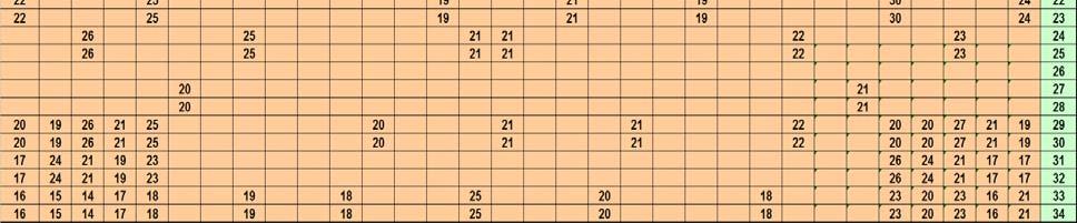
2 milliohm. This level of stability over 2 million cycles seems to be better than most test contacts available. Apparatus The data acquisition system, load cells, other commercially acquired equipment utilized in this study are listed in Attachment 2. A custom DUT board was designed that matched the 32x34 footprint of the 0.8 mm contact pads used in the actual test boards. Pad height and plating also met the design requirements. Figure 2 presents a photograph of the DUT board. Two hundred fifty eight contacts in the 1088 contact array are utilized in pairs to measure the ST contact resistance using the Kelvin Method. The 4 traces associated with each pair are routed to 4 contacts in the 50 pin connectors which are connected to the data acquisition system. Figure 3 presents a picture of the distribution of the connections utilized on the 32x34 array. This distribution was selected to provide a quality mapping of the contact resistance across the interface with key focus at the corners and middle. Note that each square in the figure represents a pad location in the array. Figure 2a
3 Figure 2b Figure 3 The ST board is a double sided board which incorporates the same pad structure at the PariPoser interface as used in the ST board. The groove in the board and the PariPoser frame are identical to that provided to the customer. Figure 4 is a photograph of the bottom side and top side of the space transformer. As seen in the picture of the top side, adjacent pads are connected with short leads to complete the 2 contact daisy chains.
4 Figure 4a Figure 4b Figure 5 provides a schematic view to indicate the daisy chain interconnection. This shows the relationship between the bottom side contacts and the leads on the top of the ST board. It should be noted that each measured chain contains 2 contacts, 4 plated thru holes and the connecting trace. Figure 5 The stack up included the test socket provided by the customer. The boards and socket were assembled with guide pins and corner mounting as done with the actual board. The static corner load used by the customer was defined as being 24 pounds per corner. The ability to do this with total accuracy using the Belleville washer structure provided was a concern. As a result we chose to use springs that were calibrated by load cells to assure we operated at the required load. It should be noted that based on past experience, we do not think that the accuracy of this load is overly critical. Figure 6 presents a photo of the assembly. Not shown is a thich Mylar sheet placed between the socket and the top of the ST. This was done to prevent any potential shorting issues between the socket contacts and the ST traces. The DUT board /ST / connector system was mounted to an aluminum plate which housed the heaters for heating the system to 110 C. Care was taken to not overly constrain the mounting structures due to a concern over thermal mismatch between the board and aluminum plate. Although the data looks good, the means to mount the board to the backing plate in a manner that deals with potential thermal mismatch is an area for future evaluation.


5 Load Cells Tekscan sensor Figure 6 The aluminum plate is integrated into a frame that houses an air cylinder for applying the dynamic cycling load. Figure 7a shows the final setup and Figure 7b shows the system fully insulated. Shown in the figure is a plastic block mounted in the socket to simulate a device. A short movie showing the cycling action is available and can be provide. Figure 7a
6 Figure 7b Overview The study was divided into two components. The first was to develop an understanding of the static load and dynamic load across the 0.8 mm pitch contact face. This was done using a combination of load cells and an array load sensor. These components are listed in Attachment 2 and the setup shown in Figure 6. Figure 9 shows the load distribution developed across the surface with the 24 pound load established at each corner. Figure 10 shows the same setup with the addition of the 24 grams per contact dynamic load applied by the cylinder. A comparison of the two figures shows the increase in load at the center. Note that the local variability is most likely caused by the sensor pixels (sencells) not being on the same pitch as the board contacts. Also the dark areas on the topo plots are due to the necessity of punching holes through the sensor interconnect so that it could fit on the hole pattern of the ST. The data shows that with the presence of a solid backing plate, the load distribution at each contact meets the design requirements for quality interconnection.


7 Figure 9 Figure 10 After completing the load analysis, the load sensors were removed and the system reassembled using the known, required spring length to re-establish the static load. The 110 C temperature cycling was initiated using a load that was ~2x the minimum load. This was done in recognition that the 32x34 array should have 24 grams per contact load for this study not the connector which had ~1/2 the number of contacts. Periodically the cycling load was held at the applied dynamic load and the resistance of the contact pairs measured. This was done at 1, 10, 100, 1000, 10,000 etc cycles to allow the generation of a logarithmic plot. Figure 11 shows the raw data for the 258 contacts measured in pairs. As shown in Figure 5, each data point consists of 2 contacts in series along with 4 plated through holes and a strap interconnecting the pair. The plot shows the data to 2,161,000 cycles. The average resistance remains very stable over the life of the study.
8 Two Contact Chain Resistance vs Cycle Count (Raw Data Including 2 PariPoser contacts, 4 PTH and Trace) Average Minimum Maximum StDev Resistance (ohms) ,001 1,000,001 1,500,001 2,000,001 Cycle Count E Figure 11 The distribution of the contact pairs plus PTH resistance of the 129 pairs at 110 C after 100,000 cycles is shown in Figure 12a. Here the data is provided in Milliohms. The resistance data after 2.1 million cycles is shown in figure 12b. The topo plot shows how little the resistance has changed over the 2 million cycles. The data of Figure 11 was modified to remove the impact of the 4 PTH and strap by removing a collective resistance of 7 milliohms for the combination. This is less that the smallest direct measurement of the stack without the PariPoser contact. The resultant was divided by 2 and the standard deviation adjusted to reflect the data being taken in pairs. This is show in Figure 13a. The corrected data shows that the average individual contact resistance has dropped from 13 to 7 milliohms over the 1st million cycles and increased to ~9 milliohm after 2 million cycles. This is consistent with previous studies done by Paricon and others. The same data is presented in a topo format in Figure 13b.


9 Figure 12a Figure 12b
10 0.05 Space Transformer Resistance vs. Cycle Life Single Contact Data Average 0.04 Minimum Maximum StDev Resistance (ohms) ,000 1,000,000 1,500,000 2,000,000 2,500,000 Cycle Count E Figure 13a Figure 13b Further analysis of the decrease in resistance over time was done with the raw data. Here, the initial resistance reading for each pair was subtracted from each subsequent reading to provide a better focus on the detailed change in resistance. The results of this are shown in Figures 14a and 14b. These plots shows that there have been 8 contacts that had an increase in resistance in excess of 2 milliohm over the life of the study little
11 change was seen until after the 1 million cycle mark. The worst of these is the lower left corner where the resistance of a contact pair rose by 11 milliohms from a low resistance of ~4.5 milliohms per contact. All of the individual pairs that rose more than 2 milliohm over the study are marked in brown. Al but one of these is in the central area of the ST and they were also in the same bank of connectors. This may be just a coincidence but will be checked to be sure that the contact on the cables are not an issue. Change in Contact Resistance vs. Cycle Count Change in Resistance (ohms) ,000 1,000,000 1,500,000 2,000, Cycle Count Figure 14 Figure 14b
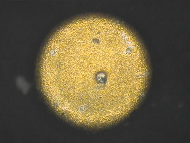
12 Post Experiment Analysis After Completing the 2 million cycle study, the space transformer was disassembled and the contact pads were inspected and photographed. Samples of the best and worst performing contact pairs are shown in Attachment 2. The photographs have been grouped in a manner that allows them to be viewed in their functional pairs. For some pairs pictures were taken through the PariPoser sheet after removing the ST board but prior to removing the PariPoser contact from the DUT board. The following observations were made. All proposed conclusions as should be viewed as being preliminary. None of the contact pads show any wear after the 2 million test cycles. The silver touch marks on the pads are indications of the location of the BallWire contacts touching the pad. This is a transfer of silver to the gold pad which has no impact on the pad performance. The size and number of silver touch marks is correlated to the resistance of the interconnection. More touch marks indicates more BallWires participating in the interconnection. Heavier silver transfer seems to indicate more intimate contact. Contact pair 22 started very low at 18 mω and rose to 29 mω over the 2 million cycles. This includes 4 PTH and strap (7mΩ). Although this started as one of the lowest (~5 mω per contact) it also had close to the greatest increase. The reason for this is not obvious but this pair is at a corner location. Contact pair 20 remained low and stable changing by only 2 mω over the life of the study. This pair has very well formed touch marks on each contact pad. It is also located next to pair 22. Contact pair number 98 started at 49 mω and rose to 63 mω over the study. This pair is representative of the highest resistance seen with the average corrected resistance going from 21 to 28 mω. Note that the BallWire touch marks are much lighter on this contact pair than on the lower resistance pairs. Again, the reason for this is not fully understood. Contact pair 9 showed a high reduction of resistance over the life of the study dropping from 38 to 18 mω. These contacts also have good touch marks but perhaps not as good as 20 and 22. One of these pads has a particle imbedded in it (see arrow). There were only ~8 observations of particles being torn from the PariPoser contact as it was being removed. This may actually be an indicator of the care used to remove the PariPoser sheet since it was well stuck to the board after the 2 million cycles. If less care is used, more particles would be torn from the matrix. Removing the PariPoser contact from the assembly probably is the major cause of contact damage. The pictures of the PariPoser material seem to show a correlation with the size of the touch marks. After 2 million cycles, there is clear indication of permanent deformation which is freezing the shape of the structure prior to disassembly. The circular marks on the PariPoser sheet indicate that the upper and lower pads were misaligned by a few mills. The BallWire columns are also distorted (perhaps) more for the lower resistance contacts indicating that there was more concentration of force at these sites. This distortion is not in a smooth bow format as indicated in our literature but more of a random squeezing outward of the particles from the column center line. This should have been expected. Conclusions The study clearly demonstrates the ability of the PariPoser contact incorporated into the ST geometry to provide low contact resistance over a long cycle life. The definition of end of life needs to be understood to fully determine the useful life of this system. Pad wear is virtually eliminated using the PariPoser contact allowing the life of the test board
13 to be greatly increased. The added cost benefit of having test boards that do not wear out opens the door to a new approach to test board design. Specifically, it should be possible to modularize the test board to have standard, base test boards that can be shared with multiple device designs. Customization can be done using one or more stacked ST boards which become low cost wear members.
14 Attachment 1 Statement of Work Paricon will develop a test capability that emulates the mechanical behavior of the test process being done by the customer. It will consist of a DUT board, PariPoser contact, adaptor board and pseudo device structure. The system will be configured to monitor the resistance of ~120 contacts in pairs using the Kelvin measurement system. These pairs will be distributed at the 4 corners of the array and the middle so as to provide an accurate test sample. Several additional contacts will be configured in an extended daisy chain to provide further information. The plating system on the contacts will be the same as used on the customer s test boards.. The structure will be housed in a structure that allows the continuous cycling of the pseudo part in the system at an applied load that approximates the test load used in production.. A load measurement system that allows the load at each contact pad will be employed to measure the actual applied loads. A load cell will also be used to measure the total load. Note that it will not be possible to measure the individual contact pad load and resistance at the same time. The ability to heat the ST / DUT board interface will be employed. A data acquisition system with meters capable of resistance measurements to under 3 mω will be used to collect the interface resistance data. Appropriate acquisition and data analysis software will be employed to provide a quality understanding of the data. Assembly of the system will incorporate a continuous load between the adaptor board and the DUT board through the PariPoser contact. The first study will be to look at the relationship between this DC load and the resistance to determine the minimum load for quality resistance contact. The second portion of the test will be to cycle the pseudo device to apply a cyclic load to the system that emulates the performance seen in production. This will be done at a temperature of 110 C. The resistance of the contacts will be monitored as a function of cycle life. The goal will be to conduct 1 million cycles as measured by a cycle counter on the system. This will be executed on 2 samples using 2 DUT, 2 adaptor boards and 2 PariPoser contactors from 2 separate manufacturing lots. The wear on the DUT board and Adaptor board pads will be evaluated by microscopic photography as a function of cycle life. A report on the life performance and pad wear will be the deliverable for this project. Paricon will develop the board designs, acquire the boards and construct the test capability. Paricon will also use its data acquisition and measurement capability. It will prepare the software needed to acquire data conduct the experimental data.

15 Attachment 2 Equipment List


16 Attachment 3 Contact Analysis BJ33 ST BJ34 ST BJ33 PP/Board BJ34 PP/Board BJ33 Board BJ34 Board Contact Pair to 29 mω


17 BG33 ST BG34 ST BG33 Board Contact Pair to 18 mω BG34 Board


18 AQ10 ST AQ11 ST AQ10 PP/Board AQ11 PP/ST AQ10 Board AQ11 Board Contact Pair to 63 mω


19 AD33 ST AD334 ST AD33 PP/Board AD34 PP/Board Contact Pair 9 38 to 18 mω
Socket Technologies
 Socket Technologies Toll Free: (800) 404-0204 U.S. Only Tel: (952) 229-8200 Fax: (952) 229-8201 email: info@ironwoodelectronics.com Introduction Company Overview Over 5,000 products High Performance Adapters
Functional Testing of 0.3mm pitch Wafer Level Packages to Multi- GHz Speed made possible by Innovative Socket Technology
 Functional Testing of 0.3mm pitch Wafer Level Packages to Multi- GHz Speed made possible by Innovative Socket Technology Ila Pal - Ironwood Electronics Introduction Today s electronic packages have high
Products, Services & Capabilities
 Products, Services & Capabilities Toll Free: (800) 404-0204 U.S. Only Tel: (952) 229-8200 Fax: (952) 229-8201 email: info@ironwoodelectronics.com Overview Company Overview Founded 1986 Over 5,000 products
Socket Technologies
 Socket Technologies Introduction Company Overview Over 5,000 products High Performance Adapters and Sockets Many Custom Designs Engineering Electrical and Mechanical ISO9001:2008 Registration Socket Technology
Achieving GHz Speed in Socketed BGA Devices
 IC INTERCONNECT TOPIC #102 Technical Information from Ironwood Electronics Achieving GHz Speed in Socketed BGA Devices Ila Pal Director of R&D Ironwood Electronics Background For many products designed
Automotive Electronics Council Component Technical Committee
 ATTACHMENT 6 AEC - Q100-006 REV-D ELECTRO-THERMALLY INDUCED PARASITIC GATE LEAKAGE TEST (GL) Acknowledgment Any document involving a complex technology brings together experience and skills from many sources.
THERMAL TESTING OF A 3D PRINTED SUPER DENSE MESH HEATSINK AGAINST STATE-OF- THE-ART FINNED GEOMETRY
 THERMAL TESTING OF A 3D PRINTED SUPER DENSE MESH HEATSINK AGAINST STATE-OF- THE-ART FINNED GEOMETRY Robert Smith, P.E., Chief Technologist AUGUST 29, 2015 QRP 6764 Airport Road West Jordan, UT 84081 www.qualifiedrapidproducts.com
Gregory Walsh, Ph.D. San Ramon, CA January 25, 2011
 Leica ScanStation:: Calibration and QA Gregory Walsh, Ph.D. San Ramon, CA January 25, 2011 1. Summary Leica Geosystems, in creating the Leica Scanstation family of products, has designed and conducted
Technical. Recommended Compression and Tension. ISO/IEC / ANSI/NCSLI Z540.3 Accredited.
 ISO/IEC 17025 / ANSI/NCSLI Z540.3 Accredited Technical Paper Recommended Compression and Tension Adapters for P: (717) 843-0081 F: (717) 846-4193 info@mhforce.com Figure 1: Bent Rod End Not using the proper
SPRING - LOADED CONNECTORS
 SPRING - LOADED CONNECTORS SPRING LOADED CONNECTORS QUICK SELECTOR CHART SPRING-LOADED CONNECTORS AND PAD CONNECTORS GRID 1.25 mm 2.54 mm SINGLE ROW SINGLE ROW DOUBLE ROW SLC CONNECTORS SEE PAGE Straight
Akrometrix Testing Applications
 Akrometrix Optical Techniques: Akrometrix Testing Applications Three full-field optical techniques, shadow moiré, digital image correlation (DIC), and fringe projection (performed by the DFP) are used
SKTM Socket Series Catalog High Speed Compression Mount
 SKTM Socket Series Catalog High Speed Compression Mount Ardent Design Support Sockets Overview Ardent Compliant Contact Technology Socket Types BGA/LGA QFN/QFP/MEMS Optical Plunge to Board Lid Types Ordering
Application Note 5363
 Surface Laminar Circuit (SLC) Ball Grid Array (BGA) Lead-free Surface Mount Assembly Application Note 5363 Introduction This document outlines the design and assembly guidelines for surface laminar circuitry
MPI TS2500-RF 200 mm Fully Automated Probe System For RF Production Test Measurements
 MPI TS2500-RF 200 mm Fully Automated Probe System For RF Production Test Measurements FEATURES / BENEFITS Designed for Wide Variety of RF On-Wafer Production Applications RF applications up to 67 GHz &
I N T E R C O N N E C T A P P L I C A T I O N N O T E. STEP-Z Connector Routing. Report # 26GC001-1 February 20, 2006 v1.0
 I N T E R C O N N E C T A P P L I C A T I O N N O T E STEP-Z Connector Routing Report # 26GC001-1 February 20, 2006 v1.0 STEP-Z CONNECTOR FAMILY Copyright 2006 Tyco Electronics Corporation, Harrisburg,
PRODUCT SPECIFCATION GS MINI-SAS HD External Cable to Board Connector System. 1 of 14 F. Roger Cheng TYPE NUMBER
 1 of 14 F TABLE OF CONTENTS 1.0 OBJECTIVE... 3 2.0 SCOPE... 3 3.0 APPLICABLE DOCUMENTS... 3 3.1 FCI SPECIFICATIONS... 3 3.2 OTHER STANDARDS AND SPECIFICATIONS... 3 3.3 FCI PRODUCT QUALIFICATION TEST REPORTS...
MACRO-SCALE PRECISION ALIGNMENT. 3.1 Precision Machine Design Alignment Principles
 Chapter 3 MACRO-SCALE PRECISION ALIGNMENT 3.1 Precision Machine Design Alignment Principles Whenever two solid bodies are positioned with respect to each other, the quality of the alignment can be described
HCI Power Connector System
 1 of 28 C Section TABLE OF CONTENTS page no. 1. OBJECTIVE... 1 2. SCOPE... 2 3. DRAWINGS AND APPLICABLE DOCUMENTS... 4 4. GENERAL CUSTOMER INFORMATION... 4 4.1 PRODUCT APPLICATION... 4 4.2 COMPATIBILITY...
Reliability Study of Bottom Terminated Components
 Reliability Study of Bottom Terminated Components Jennifer Nguyen, Hector Marin, David Geiger, Anwar Mohammed, and Murad Kurwa Flextronics International 847 Gibraltar Drive Milpitas, CA, USA Abstract Bottom
2688 WESTHILLS COURT, SIMI VALLEY, CA
 NEW PRODUCT INTRODUCTION 2688 WESTHILLS COURT, SIMI VALLEY, CA 93065-2635 To: All Hirose Sales Personnel and Partners From: Hirose USA Marketing Dept. Subject: New Product Release for IT11 Series October
360 Test Labs 4 Executive Plaza Yonkers, New York Toll-Free (855) LABS Page 1 of 8
 LABS Page 1 of 8") INTRODUCTION The MODEL # is an automotive power socket device designed to supply power to Apple portable devices that is marked with an output capability of 1000mA (1 amp). This device has a flat removable
INTRODUCTION The MODEL # is an automotive power socket device designed to supply power to Apple portable devices that is marked with an output capability of 1000mA (1 amp). This device has a flat removable
SPRING-LOADED CONNECTORS PAD CONNECTORS
 SPRING-LOADED CONNECTORS PAD CONNECTORS GENERAL SPECIFICATIONS The values listed below are general specs applying for Preci-Dip spring-loaded connectors. Please see individual catalog page for additional
Onwards and Upwards, Your near space guide Overview of the NearSys Two Sensor Temperature Array Figure 1. A complete Two Sensor Temperature Array
 The NearSys Two Sensor Temperature Array is a kit that permits a BalloonSat to measure two separate temperatures. When plugged into a flight computer like the BalloonSat Mini, the flight computer provides
PC/104, PC/104 Plus Specification
 PC/104, PC/104 Plus Specification Industry Standard bus connection systems, typically used on embedded PC applications. Designed for oard-to-oard stacking with a common bus. PC/104 Connectors mm pitch
Socket Mounting Recommendations and Reflow Profile
 Purpose This document is meant to serve as a guide for mounting E-tec surface mount device (SMD) sockets to the printed circuit board (PCB). The recommendations described here are guidelines only, and
Xkitz.com. 8 Channel Capacitive Touch Switch Model XCTS-8M. Operators Manual. Invisible Touch Switch:
 8 Channel Capacitive Touch Switch Model XCTS-8M Operators Manual Xkitz.com Invisible Touch Switch: The XCTS-8M allows you to install up to 8 capacitive touch switches nearly anywhere. It detects any sudden
TOLERANCE ALLOCATION IN FLEXIBLE ASSEMBLIES: A PRACTICAL CASE
 TOLERANCE ALLOCATION IN FLEXIBLE ASSEMBLIES: A PRACTICAL CASE Pezzuti E., Piscopo G., Ubertini A., Valentini P.P. 1, Department of Mechanical Engineering University of Rome Tor Vergata via del Politecnico
Automated Accelerated Life Testing Data Collection on Thousands of DC Passive Parts
 Automated Accelerated Life Testing Data Collection on Thousands of DC Passive Parts Jeremy Young Parts Materials and Processes Department Electronics and Sensors Division The Aerospace Corporation Microelectronics
JR3 EXTERNAL SENSOR ELECTRONICS WITH ANALOG OUTPUT. JR3, Inc. 22 Harter Ave. Woodland, CA 95776
 JR3 EXTERNAL SENSOR ELECTRONICS WITH ANALOG OUTPUT JR3, Inc. 22 Harter Ave. Woodland, CA 95776 5962C 15 December, 2003 TABLE OF CONTENTS CHAPTER 1 OVERVIEW General...1-1 Sensor...1-1 Electronic System...1-1
TB-2026 PROCESS FOR INSTALLATION OF PRESS FIT VHDM BACKPLANE CONNECTORS. Revision G
 PROCESS FOR INSTALLATION OF PRESS FIT VHDM BACKPLANE CONNECTORS Specification Revision Status Revision SCR No. Description Initial Date - 21120 Initial Release D. Manning 3-27-97 A 26393 Revised in its
TCU-100 microfluidic temperature control
 TCU-100 microfluidic temperature control Product datasheet Page Description 2 Benefits 3 Product Specifications 3 Parts List 4 Page 1 of 8 Part No. Part Description # 3200428 Meros TCU-100 1 3200197 USB
Product Specification
 SLH Series Socket, Vertical Orientation TLH Series Terminal, Vertical Orientation See www.samtec.com for more information. Page 1 1.0 SCOPE 1.1 This specification covers performance, testing and quality
Session 2. Burn-in & Test Socket Workshop Socket Design
 Session 2 Burn-in & Test Socket Workshop 2000 Socket Design BURN-IN & TEST SOCKET WORKSHOP COPYRIGHT NOTICE The papers in this publication comprise the proceedings of the 2000 BiTS Workshop. They reflect
NARROW PITCH (0.4mm) CONNECTORS P4 SERIES
 CONNECTORS P4 SERIES") Without soldering terminal With soldering terminal NARROW-PITH ONNTORS FOR BOARD-TO-BOARD AND BOARD-TO-FP ONNTION FATURS 1. 0.4 mm pitch and support for mated heights of up to 1.5 mm, 2.0 mm, 2.5 mm, 3.0
Without soldering terminal With soldering terminal NARROW-PITH ONNTORS FOR BOARD-TO-BOARD AND BOARD-TO-FP ONNTION FATURS 1. 0.4 mm pitch and support for mated heights of up to 1.5 mm, 2.0 mm, 2.5 mm, 3.0
Narrow pitch connectors (0.4mm pitch)
") AXK7L, 8L For board-to-fpc Narrow pitch connectors (0.4mm pitch) F4 Series 5.0mm 4.1mm 3. Improved mating strength between the socket and header The simple locking structures provided for the soldering
AXK7L, 8L For board-to-fpc Narrow pitch connectors (0.4mm pitch) F4 Series 5.0mm 4.1mm 3. Improved mating strength between the socket and header The simple locking structures provided for the soldering
JR3 EXTERNAL SENSOR ELECTRONICS WITH SERIAL DATA OUTPUT. JR3, Inc. 22 Harter Ave. Woodland, CA 95776
 JR3 EXTERNAL SENSOR ELECTRONICS WITH SERIAL DATA OUTPUT JR3, Inc. 22 Harter Ave. Woodland, CA 95776 5963B 13 October, 2003 TABLE OF CONTENTS CHAPTER 1 OVERVIEW General...1-1 Sensor...1-1 Electronic System...1-1
Over 5,000 products High Performance Adapters and Sockets Many Custom Designs Engineering Electrical and Mechanical ISO9001:2008 Registration
 Overview Company Overview Over 5,000 products High Performance Adapters and Sockets Many Custom Designs Engineering Electrical and Mechanical ISO9001:2008 Registration Adapter Technology Overview Pluggable
APPLICATION SPECIFICATION. 1 of 33 J (r/a header, r/a receptacle, vertical header, vertical receptacle TABLE OF CONTENTS 1. OBJECTIVE...
 1 of 33 J Section TABLE OF CONTENTS page no. 1. OBJECTIVE...2 2. SCOPE...2 3. APPLICABLE DOCUMENTS...3 4. GENERAL CUSTOMER INFORMATION...3 4.1. CONNECTOR CONFIGURATIONS...3 4.2. COMPATIBILITY WITH HARD
717 SERIES SOCKET FOR QFN/LGA PACKAGES
 717 SERIES SOCKET FOR QFN/LGA PACKAGES Features Clamshell design, compression surface mount Spring and probe contact Pointed probe maintains continuous contact to PCB Spring loaded pressure pad and locater
Orbital forming of SKF's hub bearing units
 Orbital forming of SKF's hub bearing units Edin Omerspahic 1, Johan Facht 1, Anders Bernhardsson 2 1 Manufacturing Development Centre, AB SKF 2 DYNAmore Nordic 1 Background Orbital forming is an incremental
Electrical Components Catalog Universal MATE-N-LOK Connector System
 Introduction Product Facts Pins and sockets can be intermixed in the same housing Positive polarization Rear cavity identification Contacts completely enclosed in housings Positive locking housings Insulation
Branch PLC. Velocio s Branch PLC
 Velocio s Branch PLC Branch PLC The Branch PLC is a member of the Velocio s groundbreaking series of programmable logic controllers. These PLCs introduce revolutionary new concepts, capabilities, performance
Edgecard Design Information. Polyester thermoplastic glass reinforced, UL rated 94 V-O
 Edgecard Design Information SPECIFICATIONS DAUGHTER CARD LAYOUT Installation Tooling - See end of product section pre-assembled Edgecard connectors, with C-Press contacts, combine the reliability of a
Vincotech's Compliant Pin. Application Note. Advantages of Vincotech's Power Modules with Press-fit Technology
 Application Note Vincotech's Compliant Pin Advantages of Vincotech's Power Modules with Press-fit Technology Application Note no.: AN_2010-10_001-v04 Table of Contents Revision history:... 3 1 Abstract...
HASP Payload Specification and Integration Plan
 Payload Title: Measurement of Ozone Profile in the Stratosphere Using Nanocrystalline Sensor Arrays Payload Class: Small Large (circle one) Payload ID: 7 Institution: Contact Name: Contact Phone: Contact
Aug04 Rev D EC
 Product Specification 108-1163 18Aug04 Rev D EC 0990-1127-04 Modular Plugs, Thru-Hole and Surface Mount Jacks, Data and Telephone, PCB Mounted 1. SCOPE 1.1. Content This specification covers the performance,
SILICON DESIGNS, INC Model 1210 ANALOG ACCELEROMETER
 SILICON DESIGNS, INC Model 1210 ANALOG ACCELEROMETER SENSOR TYPE: Capacitive Micromachined Nitrogen Damped Hermetically Sealed ±4V Differential Output or 0.5V to 4.5V Single Ended Output Fully Calibrated
Distinctive Characteristics
 Distinctive Characteristics Full face, bright LED illumination in choice of red, green, and amber for visible status indication. 9-amp or 6-amp electrical capacity in compact body. Interior shield prevents
GMS Interconnect Series Product Information
 GMS Interconnect Series Product Information Microwave Products Product Features: Frequency range: DC up to 23 GHz, Force to engage/disengage: 10 ounces min./2.5 pounds max., Male connectors have full self-centering
TET TOKYO ELETECH CORPORATION. Instruction for use. - Small Interface Cable Adapter - SICA14C20Z-GA101
 Instruction for use - Small Interface Cable Adapter - 14C20Z-GA101 1. Product Overview By using this adaptor to place a pad near the micro controller, it is expected to reduce the area related to tool
Ch 22 Inspection Technologies
 Ch 22 Inspection Technologies Sections: 1. Inspection Metrology 2. Contact vs. Noncontact Inspection Techniques 3. Conventional Measuring and Gaging Techniques 4. Coordinate Measuring Machines 5. Surface
High Density FPC Connector (0.3mm/0.4mm/0.5mm Pitch)
") High Density FPC Connector (0.3mm/0.4mm/0.5mm Pitch) FH16 Series FH16 Series Variation 0.3mm pitch 60 contact 0.3mm pitch 80 contact 0.3mm pitch 90 contact 0.4mm pitch 80 contact 0.5mm pitch 50 contact
High Density FPC Connector (0.3mm/0.4mm/0.5mm Pitch) FH16 Series FH16 Series Variation 0.3mm pitch 60 contact 0.3mm pitch 80 contact 0.3mm pitch 90 contact 0.4mm pitch 80 contact 0.5mm pitch 50 contact
The 2.5 mm wide ultra-slim body contributes to further miniaturization and functionality enhancement of target equipment.
 Compliance with RoHS Directive The 2.5 mm wide ultra-slim body contributes to further miniaturization and functionality enhancement of target equipment. FEATURES 1. 2.5 mm wide ultra-slim two-piece connectors
0.5mm Pitch Low-Profile Board-to-Board/Board-to-FPC Connectors
 NEW.5mm Pitch Low-Profile Board-to-Board/Board-to-FPC Connectors DF23 Series Low profile - 1.5 mm board-to-board distance Board-to-Board Application Plug Board Receptacle Plug Board FPC -.1 1.5 +.2 -.1
Without Indicator. With Indicator Model XM9B XM9B Contact Plating Specification 4: Gold Flash Plating
 LAN Modular Jack Connectors XM9B Compact LAN Modular Jack Connectors Category 5e transmission performance met for 1, 2-3, 6 pairs. (Verified with connection to Omron XS5W-T421.) Models available with and
Keywords: miniature heat sink, cryogenic electronics, thermal measurements. Abstract. Design and Construction
 ALMA MEMO NO. 437 Miniature, Modular Heat Sinks for ALMA Cryostats D. Koller, J. Effland, A. R. Kerr, K. Crady and F. Johnson National Radio Astronomy Observatory Charlottesville, VA 22903 12/02/02 Keywords:
APPLICATION NOTES. Connectors for LED Lighting Applications. Co-Planar Board Mating FIG. 1
 APPLICATION NOTES Connectors for LED Lighting Applications Mill-Max addresses the connector needs of the growing field of LED lighting applications with products such as receptacles and sockets suitable
onlinecomponents.com
 YF53 For FPC/FFC* FPC connectors (0.5mm pitch) Back lock / Series New Low profile and space saving body of 1.0 mm high and mm deep (3.70 mm including the lever) and can have a minimum of four and two contacts
PRODUCT SPECIFICATION CUSTOM CONFIGURABLE MODULAR POWER DOCK CONNECTOR SYSTEM
 1.0 SCOPE This Product Specification covers the custom configurable modular printed circuit board (PCB) Dock Connector System with gold plating. 2.0 PRODUCT DESCRIPTION 2.1 PRODUCT NAME AND SERIES NUMBER(S)
PSM-2 POWER SUPPLY MODULE INSTRUCTIONS
 PSM2-09.doc 1 Rev: 8-28-01 PSM-2 POWER SUPPLY MODULE INSTRUCTIONS PSM Model 2 equipped with Field Programmable Output Voltages MODEL PRODUCT OFFERING / VARIATIONS: PSM-2 Metal case housed surface mountable
 Distributed by: www.jameco.com -800-8-44 The content and copyrights of the attached material are the property of its owner. Pin and Socket Mini-Universal MTE-N-LOK Product Facts Compact, durable housings
ELASTOMERIC CONNECTORS. the smart solution for high-volume interconnections in compact design
 ELASTOMERIC CONNECTORS the smart solution for high-volume interconnections in compact design A NICE SIMPLE, RELIABLE CONNECTION How do elastomeric connectors work? STAX elastomers are zero insertion force
Maintaining E-Series Routers
 Maintaining E-Series Routers 9 This chapter lists the tools, items, and steps needed for installing and uninstalling E-series components. Other maintenance procedures must be performed by an authorized
Adapter guide for C167/ST10, emulators
 Adapter guide for C167/ST10, emulators As microcontrollers are getting more complex, and more pins are added, package land patterns are getting finer. This can present a problem when trying to attach an
Product specification
 SMT Modular Jack single port vertical and horizontal 1 of 12 H PAGE 1.0 OBJECTIVE 2 2.0 SCOPE 2 3.0 GENERAL 2 4.0 DEFINITIONS 3.1 Qualification 2 3.2 Material 2 3.3 Finish 2 3.4 Design and construction
Abstract. Introduction:
 Abstract This project analyzed a lifecycle test fixture for stress under generic test loading. The maximum stress is expected to occur near the shrink fit pin on the lever arm. The model was constructed
Pin-in-Paste Process Webcast
 Pin-in-Paste Process Webcast March 22, 2001 Presented By: Surface Mount Technology Laboratory David Vicari Process Research Engineer Wilhelm Prinz von Hessen Manager, Customer Process Support Jim Adriance
Mini-Universal MATE-N-LOK Connectors
 MP Mini-Universal MTE-N-LOK Product Facts Compact, durable housings Pins and sockets can be accommodated in the same housings Contacts fully protected in the housings. Both pins and sockets can be used
Best Engineering Practice to Extend the Free Air-Cooling Limit in Tablet Hand Held Devices AMD TFE 2011
 Best Engineering Practice to Extend the Free Air-Cooling Limit in Tablet Hand Held Devices AMD TFE 2011 Gamal Refai-Ahmed, Ph.D, AMD Fellow Guy Wagner, Director - Electronic Cooling Solutions William Maltz,
Ultra Small Surface Mount Coaxial Connectors 1.4mm Mated Height
 NEW Ultra Small Surface Mount Coaxial Connectors 1.4mm Mated Height W.FL Series Further downsizing of FL series in response to the market needs. Occupied Mounting Area.0.0 Features 1. Mounting area of
Mounting Instructions for MTP Modules
 VISHAY SEMICONDUCTORS www.vishay.com Modules By Kevin Liu This application note introduces Vishay s MTP rectifier-switch modules and discusses the assembly and PCB issues involved in their use. MTP modules
Colecovision 5v Memory Mod Installation
 Colecovision 5v Memory Mod Installation The Colecovision suffers from common failure points: the power supply, power switch, and 4116 DRAM. The power supply suffers from poor soldering, the power switch
TireScan Tire Footprint Pressure Mapping System
 TireScan Tire Footprint Pressure Mapping System The TireScan system is a unique tool used to capture static or dynamic tire footprint patterns using a tactile pressure sensor. The system s tailored graphing
Adapter Technologies
 Adapter Technologies Toll Free: (800) 404-0204 U.S. Only Tel: (952) 229-8200 Fax: (952) 229-8201 email: info@ironwoodelectronics.com Introduction Company Overview Over 5,000 products High Performance Adapters
The Nureva Span ideation system. Installation guide. Single panoramic system
 The Nureva Span ideation system Installation guide Single panoramic system Important SAFETY WARNINGS Prior to the installation of this product, the installation instructions should be completely read and
Getting Started. 1.3 X-MWsystem Vocabulary. X-MWprobe X-MWanchor X-MWjumper. X-MWblock RF. X-MWblock Bias and Control. X-MWprotoplate X-MWwall X-MWlid
 1. X-Microwave System (X-MWsystem) 1.1 Overview RF and Microwave design and product development is an incredibly interesting and challenging field. The Craft is truly an art and it takes years to learn
Mini-Universal MATE-N-LOK Connectors
 MP Mini-Universal MTE-N-LOK Product Facts Compact, durable housings Pins and sockets can be accommodated in the same housings Contacts fully protected in the housings. Both pins and sockets can be used
Image Processing Solutions for Probe Card Manufacturing, Inspection and Optimization
 Image Processing Solutions for Probe Card Manufacturing, Inspection and Optimization, PhD Sales Director Contents Oxford Lasers and Guide Plates The Challenges of Measuring Guide Plates Performance of
MPI TS150-HP 150 mm High Power Manual Probe System For accurate High Power measurements up to 10 kv, 600 A
 MPI TS15-HP 15 mm High Power Manual Probe System For accurate High Power measurements up to 1 kv, 6 A FEATURES / BENEFITS Universal Use Designed specifically for high power device measurement and wide
And. Modal Analysis. Using. VIC-3D-HS, High Speed 3D Digital Image Correlation System. Indian Institute of Technology New Delhi
 Full Field Displacement And Strain Measurement And Modal Analysis Using VIC-3D-HS, High Speed 3D Digital Image Correlation System At Indian Institute of Technology New Delhi VIC-3D, 3D Digital Image Correlation
BGA Socketing Systems
 DATA BOOK BGA-TECH04 (REV. 3/04) BGA Socketing Systems Search for a footprint or build a part number online at www.bgasockets.com Solutions for Virtually Any BGA Application BGA Socket Adapter System Designed
AN AUTOMATED INTERCONNECT DESIGN SYSTEM
 AN AUTOMATED INTERCONNECT DESIGN SYSTEM W. E. Pickrell Automation Systems, Incorporated INTRODUCTION This paper describes a system for automatically designing and producing artwork for interconnect surfaces.
Appendix C. Vernier Tutorial
 C-1. Vernier Tutorial Introduction: In this lab course, you will collect, analyze and interpret data. The purpose of this tutorial is to teach you how to use the Vernier System to collect and transfer
I N T E R C O N N E C T A P P L I C A T I O N N O T E. STRADA Whisper 4.5mm Connector Enhanced Backplane and Daughtercard Footprint Routing Guide
 I N T E R C O N N E C T A P P L I C A T I O N N O T E STRADA Whisper 4.5mm Connector Enhanced Backplane and Daughtercard Footprint Routing Guide Report # 32GC001 01/26/2015 Rev 3.0 STRADA Whisper Connector
The following illustration demonstrates what you would see when the print jet nozzles are properly leveled.
 INF Printing Verify the Print Jet Nozzle Level Leveling the print jet nozzles is very important to ensure quality prints especially after replacing a print jet, an extruder assembly or the print pad. The
4000 series Industrial resistive joysticks
 CABLE TECHNICAL Distinctive features and specifications Two standard mounting options Low current drain Variety of potentiometer options Robust All metal mechanism IP65 above panel Inherently immune to
Model: CAM430MV Wired Multi-View Camera with License Plate / Rear Surface Mount Installation Manual Features
 Model: CAM430MV Wired Multi-View Camera with License Plate / Rear Surface Mount Installation Manual Features Fully Adjustable, Multiple Viewing Angle Smart Camera. High Resolution, 1/2 CMOS Color Camera
SigmaCheck. Fully Featured Eddy Current Conductivity Meter ET NDE
 Fully Featured Eddy Current Conductivity Meter ET NDE Introducing The SigmaCheck APPLICATIONS Material Verification / Metal Sorting. Heat Treatment Verification. Heat or Fire Damage Investigation. Non-conductive
ECP Embedded Component Packaging Technology
 ECP Embedded Component Packaging Technology A.Kriechbaum, H.Stahr, M.Biribauer, N.Haslebner, M.Morianz, M.Beesley AT&S Austria Technologie und Systemtechnik AG Abstract The packaging market has undergone
G12/G12x USER S MANUAL
 G12/G12x USER S MANUAL TABLE OF CONTENTS SECTION 1 SLIDE CONFIGURATION SECTION 2 SLIDE CONFIGURATION ACCESSORIES SECTION 3 TABLETOP CONFIGURATION SECTION 4 TABLETOP CONFIGURATION ACCESSORIES SECTION 5
PRELIMINARY APPLICATION SPECIFICATION
 SEARAY BOARD TO BOARD INTERCONNECT SYSTEM 4970 / 466 SMT Plug Connector (shown with kapton pad for pick and place) 4971 / 467 SMT Receptacle Connector (shown with kapton pad for pick and place) SEARAY
Probe station system
 Probe station system Manufacturer: Micromanipulator Mode: 450PM-HR Descriptions: The Model 450PM 8 probe station offers stable and reliable probing performance. It is based on a design of Micromanipulator
NARROW PITCH (0.4 mm) CONNECTORS F4S SERIES
 CONNECTORS F4S SERIES") NARROW-PITCH, THIN AN SLIM CONNECTOR FOR BOAR-TO-FPC CONNECTION FEATURES 1. Space-saving (3.6 mm widthwise) The required space is smaller than our F4 series (40-contact type): 27% smaller, 38% smaller
NARROW-PITCH, THIN AN SLIM CONNECTOR FOR BOAR-TO-FPC CONNECTION FEATURES 1. Space-saving (3.6 mm widthwise) The required space is smaller than our F4 series (40-contact type): 27% smaller, 38% smaller
Using solderless breadboards
 Page 1 of 9 Using solderless breadboards This document describes how to use the solderless breadboards available in the experimental didactic lab (LED, previously LADISPE) of Politecnico di Torino. 1 Setting
FINITE ELEMENT MODELING OF THICK PLATE PENETRATIONS IN SMALL CAL MUNITIONS
 FINITE ELEMENT MODELING OF THICK PLATE PENETRATIONS IN SMALL CAL MUNITIONS Raymond Chaplin RDAR-MEM-I Picatinny Arsenal, NJ raymond.c.chaplin@us.army.mil 973-724-8562 Why Finite Element Modeling? Reduced
Byung Kim, Michael McKinley, William Vogt
 The Inflection Scaling Method: A new method for calculating J c in trouser tear specimens in presence of remote energy absorption without optical observation of crack initiation Byung Kim, Michael McKinley,
PROCESSING RECOMMENDATIONS. For Samtec s SEAM8/SEAF8 Vertical Connectors
 The method used to solder these high density connectors is the same as that used for many BGA devices even though there are some distinct structural differences. BGA s have spherical solder balls attached
Flight Data Recorder Hardware Version 1.0
 Flight Data Recorder Hardware Version 1.0 By R. G. Sparber Scope The Flight Data Recorder (FDR) hardware is described here. The software is described in a separate document. The reader can etch their own
Cutter Option Installation Instructions
 This kit includes the parts and documentation necessary to install the cutter option on the Zebra XiII, XiIII, and XiIIIPlus-Series printers. NOTE: The Cutter Option is not available for the 96XiIII. Adding
1.4 mm Pitch High Frequency Differential, Coaxial PCB Probe (40 GHz)
") D-COAX, Inc. Differential/Single-ended High Frequency Probe 1.4 mm Pitch High Frequency Differential, Coaxial PCB Probe (40 GHz) The DP1.4 Differential probe by D-COAX is used for high frequency PCB differential
D-COAX, Inc. Differential/Single-ended High Frequency Probe 1.4 mm Pitch High Frequency Differential, Coaxial PCB Probe (40 GHz) The DP1.4 Differential probe by D-COAX is used for high frequency PCB differential