IT infrastructure Efficiency-boosting solutions. nextlevel. for data centre
|
|
|
- Herbert Allen Franklin
- 6 years ago
- Views:
Transcription

1 IT infrastructure Efficiency-boosting solutions nextlevel for data centre

2 2 Rittal IT infrastructure
3 The whole is more than the sum of its parts. The same is true of Rittal The System. With this in mind, we have bundled our innovative enclosure, power distribution, climate control and IT infrastructure products together into a single system platform. Complemented by our extensive range of software tools and global service, we create unique added value for all industrial applications: Production plant, test equipment, facility management and data centres. In accordance with our simple principle, Faster better everywhere, we are able to combine innovative products and efficient service to optimum effect. Faster with our Rittal The System. range of modular solutions, which guarantees fast planning, assembly, conversion and commissioning with its system compatibility. Better by being quick to translate market trends into products. In this way, our innovative strength helps you to secure competitive advantages. Everywhere thanks to global networking across 150 locations. Rittal has over 60 subsidiaries, more than 150 service partners with over 1,000 service engineers worldwide. For more than 50 years, we have been on hand to offer advice, assistance and product solutions. Rittal IT infrastructure 3

4 4 Rittal IT infrastructure

5 IT infrastructure from the smallest to the largest RiMatrix S... from page 8 IT enclosure systems/housings... from page 18 IT power... from page 62 IT cooling... from page 80 IT monitoring... from page 96 IT security solutions... from page 118 List of model numbers... page 130 Index... page 131 Rittal IT infrastructure 5
6 6 Rittal IT infrastructure


7 Your benefits The performance and security of any IT infrastructure is determined to a significant degree by the interaction between individual components. All system components in the Rittal system platform are perfectly coordinated with one another. Modular system solutions for small to large networks Comprehensive, complete solutions for power distribution and backup, consistently modular, and flexibly extendible at any time Optimum energy and cost efficiency with maximum availability of the entire system Energy-efficient climate control concepts for rack, suite and room cooling A better overview of your IT infrastructure System-tested protection from potential physical threats Rittal IT infrastructure 7

8 RiMatrix S The first standardised data centre Standardised, off-the-shelf modules Fully pre-configured modules in the RiMatrix S series offer a pioneering alternative to building your own data centre. They already include all the necessary components such as: IT enclosure systems Power backup and distribution Climate control Monitoring and security solutions A single Model Number is all you need to order a complete RiMatrix S module. Complete RiMatrix S data centres can be assembled in next to no time, because all modules are available off the shelf. 8 Rittal IT infrastructure

9 Rittal IT infrastructure 9

10 RiMatrix S The standardised data centre 10


11 IT infrastructure Fully operational Pre-configured modules ready for immediate installation of the IT equipment Fully functional complete system including server and network enclosures, climate control, power distribution and backup, monitoring and optionally with RiZone, the DCIM (Data Center Infrastructure Management) system Peace of mind due to documented system test of the entire module Available within 6 weeks Complete and off the shelf Order RiMatrix S with just one model number for the entire data centre Supplied off the shelf Lead time from ordering to commissioning: just 6 weeks The right physical structure for every requirement The modules are supplied with the right physical structure to suit the application: In a standard room In a standard security room for installation in existing properties In a standard container for outdoor siting Rittal IT infrastructure 11
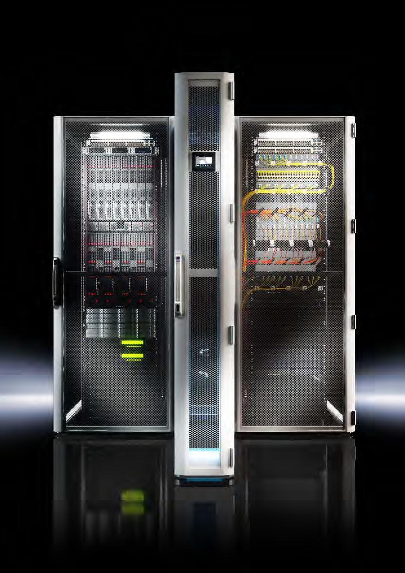
12 RiMatrix S The standardised data centre is assembled at your premises within the context of hot aisle / cold aisle containment. Benefits: Enhanced energy efficiency Aisle containment is a combination of door and roof components which allow consistent separation of the hot and cold air Protection category IP to IEC : IP 20 in the protected area above the raised floor Supply includes: Advice and ROI calculation Delivery and integration into the customer infrastructure Commissioning and handover Documentation, training and instruction Hotline and service/service agreements Precise-fit aisle containment Photo shows a configuration example with equipment not included in the scope of supply Standard room Packs of Single 6 Double 6 Single 9 Double 9 Page External dimensions, width mm External dimensions, height mm External dimensions, depth mm Interior dimensions, width mm Interior dimensions, height mm Interior dimensions, depth mm Model No. 1 pc(s) Early fire detection Room extinguisher system optional optional optional optional Humidification and dehumidification system optional optional optional optional Server rack (600 x 2000 x 1200 mm) Combined network/server rack (800 x 2000 x 1200 mm) Uninterruptible power supply 60 kw + 20 kw n+1 redundant 2 x (60 kw + 20 kw) n+1 redundant Low-voltage main distributor PDU Basic Climate control (ZUCS) 60 kw + 10 kw n+1 redundant 120 kw + 20 kw n+2 redundant 90 kw + 10 kw n+1 redundant 180 kw + 20 kw n+2 redundant 12 Rittal IT infrastructure
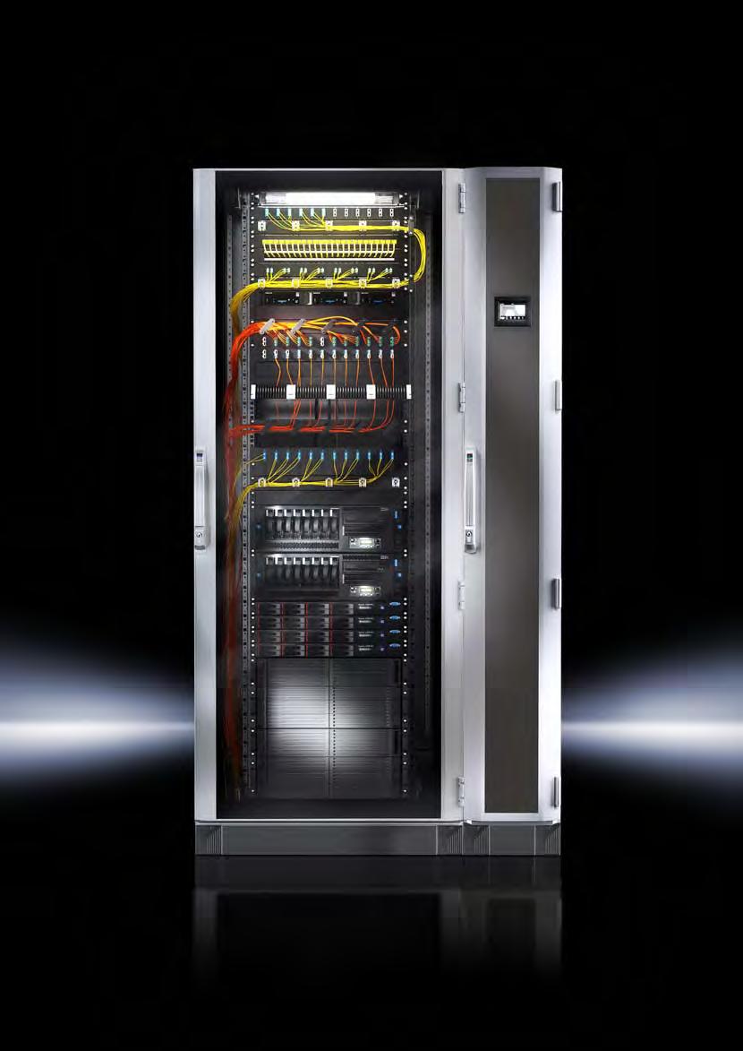
13 RiMatrix S The standardised data centre at your premises is equipped with an additional security room (roomwithin-a-room) to provide additional protection from fire, water and smoke. Protection standards: Fire resistance EI 90 to EN 1363/F 90 to DIN 4102 Dust- and watertight IP 56 to IEC Protection from unauthorised access Resistance class II EMC basic protection Acrid gas-tightness, based on EN (DIN 18095) Shock test with 3,000 Nm energy after 30 minutes flame impingement over standard temperature curve Material: Element core made of thermally effective insulation substance Robust, encapsulated sheet steel cassette panels Innovative connection technology using patented profile technology Use of temperature- and humidity-resistant seals Use of fire protection valves Dismantling and reassembly is possible at any time Supply includes: Advice and ROI calculation Delivery and integration into the customer infrastructure Commissioning and handover Documentation, training and instruction Hotline and service/service agreements Photo shows a configuration example with equipment not included in the scope of supply Standard security room Packs of Single 6 Double 6 Single 9 Double 9 Page External dimensions, width mm External dimensions, height mm External dimensions, depth mm Interior dimensions, width mm Interior dimensions, height mm Interior dimensions, depth mm Model No. 1 pc(s) Fire protection EI 90 to EN 1363 / F 90 to DIN 4102 EI 90 to EN 1363 / F 90 to DIN 4102 EI 90 to EN 1363 / F 90 to DIN 4102 EI 90 to EN 1363 / F 90 to DIN 4102 Burglar resistance WK II WK II WK II WK II Early fire detection Room extinguisher system optional optional optional optional Humidification and dehumidification system optional optional optional optional Server rack (600 x 2000 x 1200 mm) Combined network/server rack (800 x 2000 x 1200 mm) Uninterruptible power supply 60 kw + 20 kw n+1 redundant 2 x (60 kw + 20 kw) n+1 redundant Low-voltage main distributor PDU Basic Climate control (ZUCS) 60 kw + 10 kw n+1 redundant 120 kw + 20 kw n+2 redundant 90 kw + 10 kw n+1 redundant 180 kw + 20 kw n+2 redundant Rittal IT infrastructure 13
14 RiMatrix S The standardised data centre is implemented in a container solution and can therefore be sited outdoors if required. Protection standards: Vandal-proof interior in accordance with Resistance Class II to DIN EN 1631 Fire resistance EI 30 to EN 1363 EMC basic protection Dust- and watertight to IP 55 to IEC Supply includes: Robust sheet steel container with reinforced frame structure for optimum weight distribution Housed interior wall structure with thermal insulating materials Advice and ROI calculation Delivery and integration into the customer infrastructure Documentation, training and instruction Hotline and service/service agreements Photo shows a configuration example with equipment not included in the scope of supply Standard container Packs of Single 6 Single 9 Page External dimensions, width mm External dimensions, height mm External dimensions, depth mm Interior dimensions, width mm Interior dimensions, height mm Interior dimensions, depth mm Model No. 1 pc(s) Early fire detection Room extinguisher system optional optional Humidification and dehumidification system optional optional Server rack (600 x 2000 x 1200 mm) 6 8 Combined network/server rack (800 x 2000 x 1200 mm) 1 1 Uninterruptible power supply 60 kw + 20 kw n+1 redundant Low-voltage main distributor 1 1 PDU Basic Climate control (ZUCS) 60 kw + 10 kw n+1 redundant 90 kw + 10 kw n+1 redundant 14 Rittal IT infrastructure


15 RiMatrix S Selector on the Web and as an app 15
16 RiMatrix The system for customer-specific IT solutions IT components for modern infrastructures If you want to assemble and expand a modular IT system, step by step, you've come to the right place. The RiMatrix system from Rittal offers a huge range of components for flexible configuration of forward-looking data centre infrastructures. The broad range includes IT enclosure systems and housings IT power IT cooling IT monitoring IT security solutions All components are available off the shelf with short delivery times. 16 Rittal IT infrastructure
17 Rittal IT infrastructure 17

18 Rittal IT infrastructure

19 IT enclosure systems/cases The Rittal TS IT sets global standards in network and server technology. The intelligent modular system comprising a range of racks and accessories, coupled with assembly-friendly snap-in technology, means that almost any requirement for modular network and server racks can be met with a single, standardised rack. 5 Your benefits Network/server enclosures Individually usable for stand-alone siting and data centres Complete system solutions for small to large networks Maximum configuration diversity and protection for installed equipment Investment protection and flexibility, thanks to simple conversions and use of our extensive modular system Wall-mounted enclosures Choose from an extensive range of products the right enclosure to suit any application up to protection category IP 66 Wide choice of sizes available from 3 U to 21 U Wide choice of accessories with "Rittal The System." Fast assembly, conversion and simple installation based on the modular principle Sample applications Wall-mounted enclosures EL, see page 56 VerticalBox, see Cat. 34, page 97 Wall-mounted enclosures AE with mm (19 ) mounting angles, see page 60 TS IT with glazed door, see page 32, base/plinth and installation accessories, see Cat. 34, page 507 TS IT with vented door, see page 35, bayed with base/plinth and installation accessories, see Cat. 34, page 507 Rittal IT infrastructure 19

20 Network/server enclosures TS IT 20 Rittal IT infrastructure
 mounting levels.")
21 The benefits at a glance Individual configuration The ideal basis for virtually all network and server technology requirements High load capacity and variable interior installation Load capacity of up to 1,500 kg and tool-free adjustment of the mm (19 ) mounting levels. Tool-free installation System accessory mounting using new, time-saving snap-in technology (available for component shelves, cable conduits, etc.) Intelligent cable management Multi-functional roof for side cable entry, ensures maximum user-friendliness and free air flow for active components Fast side panel assembly Divided side panel with quick-release fasteners, integral lock and internal latch Convincing door concept Glazed door for high-performance server applications with LCP climate control or vented doors for room climate control Divided rear doors Divided rear doors from a height of 1,800 mm for space-optimised positioning Intelligent accessories Simple and quick selection of system accessories using the new TS IT concept Simple positioning Labelling of the height units and pitch pattern in the depth for simple adjustment of the distance between mm (19 ) levels Enhanced safety Variants with protection category IP 55, both with and without mm (19 ) interior installation Pre-configured complete packages More than 100 different installation variants available for fast delivery Rittal IT infrastructure 21
 mounting frame Front door Glazed door Vented door Glazed door Vented door Variants 55XX.120 55XX.110 55XX.141 55XX.")
22 Network/server enclosures TS IT mm (19 ) installation With mm (19 ) mounting angles With mm (19 ) mounting frame Front door Glazed door Vented door Glazed door Vented door Variants 55XX XX XX XX.181 Product-specific scope of supply Base Open Solid One-piece, solid Two-piece, solid Rear door One-piece, vented Two-piece from H 1800 mm, vented Rear panel, screw-fastened With cable entry Roof Solid Pre-configured Base/plinth Flex-Block, vented Solid front, one base module Base One-piece, vented Walls One-piece, lockable Page Rittal IT infrastructure
 mounting frame, protection category IP 55 Without interior installation, protection category IP 55 Glazed door Vented door Glazed door Glazed door Glazed door 55XX.151 55XX.161 55XX.")
23 Network/server enclosures TS IT With mm (19 ) mounting frame, pre-configured With mm (19 ) swing frame, pre-configured With mm (19 ) mounting frame, protection category IP 55 Without interior installation, protection category IP 55 Glazed door Vented door Glazed door Glazed door Glazed door 55XX XX XX XX XX Rittal IT infrastructure 23
 mounting angles 24 Rittal IT")
24 Network/server enclosures TS IT with mm (19 ) mounting angles 24 Rittal IT infrastructure
 mounting angles Alternative mounting dimensions, such as 21 24, are easily achieved 482.")

 mounting angles Direct, space-saving integration of cable management and Dynamic Rack Control")

25 User benefits Tool-free depth adjustment of the front and rear mm (19 ) mounting angles Alternative mounting dimensions, such as 21 24, are easily achieved mm (19 ) installation mm (19 ) mounting angles, max. load capacity 1,500 kg Tool-free attachment of accessory components Front and rear labelling of the individual height units on the mm (19 ) mounting angles Direct, space-saving integration of cable management and Dynamic Rack Control at the front, or a rear PDU, directly on the mounting angle Rack configuration Optimum cable routing due to Side brush strips in the roof across the entire enclosure depth Rear brush strips in the enclosure width at an enclosure depth of 600 mm Doors solid or slotted Divided rear doors from a height of 1800 mm, for space-optimised positioning Rittal IT infrastructure 25
26 Network/server enclosures TS IT with mm (19 ) mounting frame 26 Rittal IT infrastructure
 levels Side cable management easily achieved across all height units 482.6 mm (19 ) installation 482.")


27 User benefits Simple depth adjustment of the front and rear mm (19 ) levels Side cable management easily achieved across all height units mm (19 ) installation mm (19 ) mounting frame, max. load capacity 1,000 kg Optimum cable routing within the mounting level and between bayed systems Tool-free attachment of accessory components Front and rear labelling of the individual height units on the mounting level Direct space-saving integration of cable management and Dynamic Rack Control at the front, or a rear PDU, directly on the mounting frame Rack configuration Optimum cable routing due to Side brush strips in the roof across the entire enclosure depth Rear brush strips in the enclosure width at an enclosure depth of 600 mm Doors solid or slotted Divided rear doors from a height of 1800 mm, for space-optimised positioning Special configuration variants IP 55 version available Pre-configured with Flex-Block base/plinth system Tested potential equalisation Lockable side panels and Practical accessories supplied loose Rittal IT infrastructure 27
28 Network/server enclosures TS IT with swing frame 28 Rittal IT infrastructure
 components, thanks to the swing frame with 130 opening angle 482.")
 swing frame, maximum load capacity 150 kg, with side lock panel and 3-point locking rod Rack")

29 User benefits For siting directly on the wall or in niches Direct access to the rear of the mm (19 ) components, thanks to the swing frame with 130 opening angle mm (19 ) installation Large mm (19 ) swing frame, maximum load capacity 150 kg, with side lock panel and 3-point locking rod Rack configuration Optimum cable routing, due to side brush strips in the roof across the entire enclosure depth Glazed door at the front, rear panel screw-fastened Pre-configured with Flex-Block base/plinth system Tested potential equalisation Lockable side panels and Practical accessories supplied loose Rittal IT infrastructure 29

30 Network/server enclosures TS IT empty enclosure, without interior installation 30 Rittal IT infrastructure

 installation Without interior installation Rack configuration Glazed front door,")

31 User benefits Tested protection category IP 55, in conjunction with sealing kit for bayed siting, or screw-fastened side panels for stand-alone siting Individual configuration with shelves, mm (19 ) mounting angles or swing frames, combinations also supported mm (19 ) installation Without interior installation Rack configuration Glazed front door, sheet steel rear door Solid base Solid roof plate Connection accessories for potential equalisation with earthing point are supplied loose with the enclosure Rittal IT infrastructure 31
32 Network/server enclosures TS IT IT power Page 63 IT cooling Page 81 IT monitoring Page 97 System accessories Cat. 34, Page 507 Material: Sheet steel Aluminium Glazed door: Single-pane safety glass, 3 mm Surface finish: Enclosure frame: Dipcoatprimed Interior installation: Dipcoatprimed Doors and roof: Dipcoatprimed, powder-coated Colour: Enclosure frame and panels: RAL 7035 Interior installation: RAL 9005 Load capacity of the mm (19") mounting angles: N Supply includes: TS 8 enclosure frame with doors and roof plate Glazed aluminium door at the front, 180 hinges Lock front and rear: Comfort handle for semi-cylinders and security lock 3524 E Two mm (19") mounting sections front and rear, variably mounted on support strips with quick-release fasteners Spacers to raise the fan cover plate, for passive cooling (supplied loose) Connection accessories for potential equalisation with earthing point (supplied loose) 50 multi-tooth screws M5, cage nuts M5, conductive (supplied loose) Please observe the productspecific scope of supply. Note: Depending on the siting type and location, the door opening may vary for selected applications Approvals: UL cul Technical details: Available on the Internet with glazed door, with mm (19") mounting angles Units U Packs of Cat. 34, Page Width mm Height mm Depth mm Distance between prefitted mm (19") levels mm Model No. 1 pc(s) Product-specific scope of supply Roof plate, multi-piece, removable, for horizontal cable entry at the rear and covered cut-out for fan mounting plate 1 pc(s). Sheet steel door at the rear, 180 hinges 1 pc(s). Roof plate, multi-piece, removable, with side cable entry in the depth and covered cut-out for fan mounting plate 1 pc(s). Sheet steel door at the rear, vertically divided, 180 hinges 1 pc(s). Accessories Side panel, lockable 2 pc(s) Side panels, divided Baying connector, external 6 pc(s) Fan mounting plates 1 pc(s) Base/plinth from page from page from page from page from page 510 Base mount 2 pc(s) Gland plates 1 set(s) C rails, for depth 4 pc(s) C rails, for width 4 pc(s) Cable clamp rails, for depth 4 pc(s) Cable clamp rails, for width 4 pc(s) Slide rails from page from page from page from page from page 687 Component shelves from page from page from page from page from page Rittal IT infrastructure
33 with glazed door, with mm (19") mounting angles with glazed door, with mm (19") mounting angles Network/server enclosures TS IT Units U Packs of Width mm Height mm Depth mm Distance between prefitted mm (19") levels mm Model No. 1 pc(s) Product-specific scope of supply Roof plate, multi-piece, removable, with side cable entry in the depth and covered cut-out for fan mounting plate 1 pc(s). Sheet steel door at the rear, vertically divided, 180 hinges 1 pc(s). Roof plate, multi-piece, removable, for horizontal cable entry at the rear and covered cut-out for fan mounting plate 1 pc(s). Accessories Side panel, lockable 2 pc(s) Side panels, divided 1 pc(s) Baying connector, external 6 pc(s) Fan mounting plates 1 pc(s) Base/plinth from page from page from page from page 510 Base mount 2 pc(s) Gland plates 1 set(s) Air baffle plates 1 set(s) Cable route 1 pc(s) C rails, for depth 4 pc(s) C rails, for width 4 pc(s) Cable clamp rails, for depth 4 pc(s) Cable clamp rails, for width 4 pc(s) Slide rails from page from page from page from page 687 Component shelves from page from page from page from page 627 Units U Packs of Cat. 34, Page Width mm Height mm Depth mm Distance between prefitted mm (19") levels mm Model No. 1 pc(s) Product-specific scope of supply Roof plate, multi-piece, removable, with side cable entry in the depth and covered cut-out for fan mounting plate 1 pc(s). Sheet steel door at the rear, vertically divided, 180 hinges 1 pc(s). Roof plate, multi-piece, removable, for horizontal cable entry at the rear and covered cut-out for fan mounting plate 1 pc(s). Accessories Side panel, lockable 2 pc(s) Side panels, divided 1 pc(s) Baying connector, external 6 pc(s) Fan mounting plates 1 pc(s) Base/plinth from page from page from page from page 510 Base mount 2 pc(s) Gland plates 1 set(s) Air baffle plates 1 set(s) Cable route 1 pc(s) C rails, for depth 4 pc(s) C rails, for width 4 pc(s) Cable clamp rails, for depth 4 pc(s) Cable clamp rails, for width 4 pc(s) Slide rails from page from page from page from page 687 Component shelves from page from page from page from page 627 Cat. 34, Page Rittal IT infrastructure 33
34 Network/server enclosures TS IT with glazed door, with mm (19") mounting angles Units U Packs of Width mm Height mm Depth mm Distance between prefitted mm (19") levels mm Model No. 1 pc(s) Product-specific scope of supply Roof plate, multi-piece, removable, with side cable entry in the depth and covered cut-out for fan mounting plate 1 pc(s). Sheet steel door at the rear, vertically divided, 180 hinges 1 pc(s). Accessories Side panel, lockable 2 pc(s) Side panels, divided 1 pc(s) Baying connector, external 6 pc(s) Fan mounting plates 1 pc(s) Base/plinth from page from page from page from page 510 Base mount 2 pc(s) Gland plates 1 set(s) Air baffle plates 1 set(s) Cable route 1 pc(s) C rails, for depth 4 pc(s) C rails, for width 4 pc(s) Cable clamp rails, for depth 4 pc(s) Cable clamp rails, for width 4 pc(s) Slide rails from page from page from page from page 687 Component shelves from page from page from page from page 627 with glazed door, with mm (19") mounting angles Units U Packs of Cat. 34, Page Width mm Height mm Depth mm Distance between prefitted mm (19") levels mm Model No. 1 pc(s) Product-specific scope of supply Roof plate, multi-piece, removable, with side cable entry in the depth and covered cut-out for fan mounting plate 1 pc(s). Sheet steel door at the rear, vertically divided, 180 hinges 1 pc(s). Accessories Side panel, lockable 2 pc(s) Side panels, divided 1 pc(s) Baying connector, external 6 pc(s) Fan mounting plates 1 pc(s) Base/plinth from page from page from page from page 510 Base mount 2 pc(s) Gland plates 1 set(s) Air baffle plates 1 set(s) Cable route 1 pc(s) C rails, for depth 4 pc(s) C rails, for width 4 pc(s) Cable clamp rails, for depth 4 pc(s) Cable clamp rails, for width 4 pc(s) Slide rails from page from page from page from page 687 Component shelves from page from page from page from page 627 Cat. 34, Page 34 Rittal IT infrastructure
35 Network/server enclosures TS IT IT power Page 63 IT cooling Page 81 IT monitoring Page 97 System accessories Cat. 34, Page 507 Material: Sheet steel Aluminium Surface finish: Enclosure frame: Dipcoatprimed Interior installation: Dipcoatprimed Doors and roof: Dipcoatprimed, powder-coated Colour: Enclosure frame and panels: RAL 7035 Interior installation, vent grille at the front: RAL 9005 Load capacity of the mm (19") mounting angles: N Supply includes: TS 8 enclosure frame with doors and roof plate Aluminium sheet steel door at the front, vented (vented surface area approx. 85% perforated), 180 hinges Lock front and rear: Comfort handle for semi-cylinders and security lock 3524 E Two mm (19") mounting sections front and rear, variably mounted on support strips with quick-release fasteners Spacers to raise the fan cover plate, for passive cooling (supplied loose) Connection accessories for potential equalisation with earthing point (supplied loose) 50 multi-tooth screws M5, cage nuts M5, conductive (supplied loose) Please observe the productspecific scope of supply. Note: Depending on the siting type and location, the door opening may vary for selected applications Approvals: UL cul Technical details: Available on the Internet with vented door, with mm (19") mounting angles Units U Packs of Cat. 34, Page Width mm Height mm Depth mm Distance between prefitted mm (19") levels mm Model No. 1 pc(s) Product-specific scope of supply Roof plate, multi-piece, removable, for horizontal cable entry at the rear and covered cut-out for fan mounting plate 1 pc(s). Sheet steel door at the rear, vented (vented surface area approx. 85% perforated), 180 hinges 1 pc(s). Roof plate, multi-piece, removable, with side cable entry in the depth and covered cut-out for fan mounting plate 1 pc(s). Sheet steel door at the rear, vertically divided, vented (vented surface area approx. 85% perforated), 180 hinges 1 pc(s). Accessories Side panel, lockable 2 pc(s) Side panels, divided 1 pc(s) Baying connector, external 6 pc(s) Fan mounting plates 1 pc(s) Base/plinth from page from page from page from page from page 510 Base mount 2 pc(s) Gland plates 1 set(s) C rails, for depth 4 pc(s) C rails, for width 4 pc(s) Cable clamp rails, for depth 4 pc(s) Cable clamp rails, for width 4 pc(s) Rittal IT infrastructure 35
36 Network/server enclosures TS IT with vented door, with mm (19") mounting angles Units U Packs of Width mm Height mm Depth mm Distance between prefitted mm (19") levels mm Model No. 1 pc(s) Product-specific scope of supply Roof plate, multi-piece, removable, with side cable entry in the depth and covered cut-out for fan mounting plate 1 pc(s). Sheet steel door at the rear, vertically divided, vented (vented surface area approx. 85% perforated), 180 hinges 1 pc(s). Roof plate, multi-piece, removable, for horizontal cable entry at the rear and covered cut-out for fan mounting plate 1 pc(s). Accessories Side panel, lockable 2 pc(s) Side panels, divided 1 pc(s) Baying connector, external 6 pc(s) Fan mounting plates 1 pc(s) Base/plinth from page from page from page from page from page 510 Base mount 2 pc(s) Gland plates 1 set(s) Air baffle plates 1 set(s) Cable route 1 pc(s) C rails, for depth 4 pc(s) C rails, for width 4 pc(s) Cable clamp rails, for depth 4 pc(s) Cable clamp rails, for width 4 pc(s) with vented door, with mm (19") mounting angles Units U Packs of Cat. 34, Page Width mm Height mm Depth mm Distance between prefitted mm (19") levels mm Model No. 1 pc(s) Product-specific scope of supply Roof plate, multi-piece, removable, for horizontal cable entry at the rear and covered cut-out for fan mounting plate 1 pc(s). Sheet steel door at the rear, vertically divided, vented (vented surface area approx. 85% perforated), 180 hinges 1 pc(s). Roof plate, multi-piece, removable, with side cable entry in the depth and covered cut-out for fan mounting plate 1 pc(s). Accessories Side panel, lockable 2 pc(s) Side panels, divided 1 pc(s) Baying connector, external 6 pc(s) Fan mounting plates 1 pc(s) Base/plinth from page from page from page from page from page 510 Base mount 2 pc(s) Gland plates 1 set(s) Air baffle plates 1 set(s) Cable route 1 pc(s) C rails, for depth 4 pc(s) C rails, for width 4 pc(s) Cable clamp rails, for depth 4 pc(s) Cable clamp rails, for width 4 pc(s) Cat. 34, Page 36 Rittal IT infrastructure
 mounting angles Network/server enclosures TS IT Units U Packs of 47 47 47 47 47 Width mm 600 600 800 800 800 Height mm 2200 2200 2200 2200 2200 Depth mm 1000 1200 800 1000 1200 Distance")
37 with vented door, with mm (19") mounting angles Network/server enclosures TS IT Units U Packs of Width mm Height mm Depth mm Distance between prefitted mm (19") levels mm Model No. 1 pc(s) Product-specific scope of supply Roof plate, multi-piece, removable, with side cable entry in the depth and covered cut-out for fan mounting plate 1 pc(s). Sheet steel door at the rear, vertically divided, vented (vented surface area approx. 85% perforated), 180 hinges 1 pc(s). Accessories Side panel, lockable 2 pc(s) Side panels, divided 1 pc(s) Baying connector, external 6 pc(s) Fan mounting plates 1 pc(s) Base/plinth from page from page from page from page from page 510 Base mount 2 pc(s) Gland plates 1 set(s) Air baffle plates 1 set(s) Cable route 1 pc(s) C rails, for depth 4 pc(s) C rails, for width 4 pc(s) Cable clamp rails, for depth 4 pc(s) Cable clamp rails, for width 4 pc(s) Cat. 34, Page PDU Power Distribution Unit see page 66 New Rittal IT infrastructure 37
38 Network/server enclosures TS IT IT power Page 63 IT cooling Page 81 IT monitoring Page 97 System accessories Cat. 34, Page 507 Material: Sheet steel Aluminium Glazed door: Single-pane safety glass, 3 mm Surface finish: Enclosure frame: Dipcoatprimed Interior installation: Dipcoatprimed Doors and roof: Dipcoatprimed, powder-coated Colour: Enclosure frame and panels: RAL 7035 Interior installation: RAL 9005 Load capacity of the mm (19") mounting angles: N Supply includes: TS 8 enclosure frame with doors and roof plate Glazed aluminium door at the front, 180 hinges Lock front and rear: Comfort handle for semi-cylinders and security lock 3524 E Two mm (19") mounting frames, front and rear, depthvariable Spacers to raise the fan cover plate, for passive cooling (supplied loose) Connection accessories for potential equalisation with earthing point (supplied loose) 50 multi-tooth screws M5, cage nuts M5, conductive (supplied loose) Please observe the productspecific scope of supply. Note: Depending on the siting type and location, the door opening may vary for selected applications Approvals: UL cul Technical details: Available on the Internet with glazed door, with mm (19") mounting frame Units U Packs of Cat. 34, Page Width mm Height mm Depth mm Distance between prefitted mm (19") levels mm Model No. 1 pc(s) Product-specific scope of supply Roof plate, multi-piece, removable, for horizontal cable entry at the rear and covered cut-out for fan mounting plate 1 pc(s). Sheet steel door at the rear, 180 hinges 1 pc(s). Roof plate, multi-piece, removable, with side cable entry in the depth and covered cut-out for fan mounting plate 1 pc(s). Sheet steel door at the rear, vertically divided, 180 hinges 1 pc(s). Accessories Side panel, lockable 2 pc(s) Side panels, divided 1 pc(s) Baying connector, external 6 pc(s) Fan mounting plates 1 pc(s) Base/plinth from page from page from page from page from page 510 Base mount 2 pc(s) Gland plates 1 set(s) Air baffle plates 1 set(s) C rails, for depth 4 pc(s) C rails, for width 4 pc(s) Cable clamp rails, for depth 4 pc(s) Cable clamp rails, for width 4 pc(s) Rittal IT infrastructure
39 with glazed door, with mm (19") mounting frame with glazed door, with mm (19") mounting frame Network/server enclosures TS IT Units U Packs of Width mm Height mm Depth mm Distance between prefitted mm (19") levels mm Model No. 1 pc(s) Product-specific scope of supply Roof plate, multi-piece, removable, with side cable entry in the depth and covered cut-out for fan mounting plate 1 pc(s). Sheet steel door at the rear, vertically divided, 180 hinges 1 pc(s). Roof plate, multi-piece, removable, for horizontal cable entry at the rear and covered cut-out for fan mounting plate 1 pc(s). Accessories Side panel, lockable 2 pc(s) Side panels, divided 1 pc(s) Baying connector, external 6 pc(s) Fan mounting plates 1 pc(s) Base/plinth from page from page from page from page from page 510 Base mount 2 pc(s) Gland plates 1 set(s) Air baffle plates 1 set(s) Cable route 1 pc(s) C rails, for depth 4 pc(s) C rails, for width 4 pc(s) Cable clamp rails, for depth 4 pc(s) Cable clamp rails, for width 4 pc(s) Units U Packs of Cat. 34, Page Width mm Height mm Depth mm Distance between prefitted mm (19") levels mm Model No. 1 pc(s) Product-specific scope of supply Roof plate, multi-piece, removable, for horizontal cable entry at the rear and covered cut-out for fan mounting plate 1 pc(s). Sheet steel door at the rear, vertically divided, 180 hinges 1 pc(s). Roof plate, multi-piece, removable, with side cable entry in the depth and covered cut-out for fan mounting plate 1 pc(s). Accessories Side panel, lockable 2 pc(s) Side panels, divided 1 pc(s) Baying connector, external 6 pc(s) Fan mounting plates 1 pc(s) Base/plinth from page from page from page from page from page 510 Base mount 2 pc(s) Gland plates 1 set(s) see page Air baffle plates 1 set(s) Cable route 1 pc(s) C rails, for depth 4 pc(s) C rails, for width 4 pc(s) Cable clamp rails, for depth 4 pc(s) Cable clamp rails, for width 4 pc(s) Cat. 34, Page Rittal IT infrastructure 39
 mounting frame Units U Packs of 47 47 47 47 47 Width mm 600 600 800 800 800 Height mm 2200 2200 2200 2200 2200 Depth mm 1000 1200 800 1000 1200 Distance between prefitted 482.")
40 Network/server enclosures TS IT with glazed door, with mm (19") mounting frame Units U Packs of Width mm Height mm Depth mm Distance between prefitted mm (19") levels mm Model No. 1 pc(s) Product-specific scope of supply Roof plate, multi-piece, removable, with side cable entry in the depth and covered cut-out for fan mounting plate 1 pc(s). Sheet steel door at the rear, vertically divided, 180 hinges 1 pc(s). Accessories Side panel, lockable 2 pc(s) Side panels, divided 1 pc(s) Baying connector, external 6 pc(s) Fan mounting plates 1 pc(s) Base/plinth from page from page from page from page from page 510 Base mount 2 pc(s) Gland plates 1 set(s) Air baffle plates 1 set(s) Cable route 1 pc(s) C rails, for depth 4 pc(s) C rails, for width 4 pc(s) Cable clamp rails, for depth 4 pc(s) Cable clamp rails, for width 4 pc(s) Cat. 34, Page LCP Liquid Cooling Package see page 82 New 40 Rittal IT infrastructure
41 Network/server enclosures TS IT IT power Page 63 IT cooling Page 81 IT monitoring Page 97 System accessories Cat. 34, Page 507 Material: Sheet steel Aluminium Surface finish: Enclosure frame: Dipcoatprimed Interior installation: Dipcoatprimed Doors and roof: Dipcoatprimed, powder-coated Colour: Enclosure frame and panels: RAL 7035 Interior installation, vent grille at the front: RAL 9005 Load capacity of the mm (19") mounting angles: N Supply includes: TS 8 enclosure frame with doors and roof plate Aluminium sheet steel door at the front, vented (vented surface area approx. 85% perforated), 180 hinges Lock front and rear: Comfort handle for semi-cylinders and security lock 3524 E Two mm (19") mounting frames, front and rear, depthvariable Spacers to raise the fan cover plate, for passive cooling (supplied loose) Connection accessories for potential equalisation with earthing point (supplied loose) 50 multi-tooth screws M5, cage nuts M5, conductive (supplied loose) Please observe the productspecific scope of supply. Note: Depending on the siting type and location, the door opening may vary for selected applications Approvals: UL cul Technical details: Available on the Internet with vented door, with mm (19") mounting frame Units U Packs of Cat. 34, Page Width mm Height mm Depth mm Distance between prefitted mm (19") levels mm Model No. 1 pc(s) Product-specific scope of supply Roof plate, multi-piece, removable, for horizontal cable entry at the rear and covered cut-out for fan mounting plate 1 pc(s). Sheet steel door at the rear, vented (vented surface area approx. 85% perforated), 180 hinges 1 pc(s). Roof plate, multi-piece, removable, with side cable entry in the depth and covered cut-out for fan mounting plate 1 pc(s). Sheet steel door at the rear, vertically divided, vented (vented surface area approx. 85% perforated), 180 hinges 1 pc(s). Accessories Side panel, lockable 2 pc(s) Side panels, divided 1 pc(s) Baying connector, external 6 pc(s) Fan mounting plates 1 pc(s) Base/plinth from page from page from page from page from page 510 Base mount 2 pc(s) Gland plates 1 set(s) Air baffle plates 1 set(s) C rails, for depth 4 pc(s) C rails, for width 4 pc(s) Cable clamp rails, for depth 4 pc(s) Rittal IT infrastructure 41
42 Network/server enclosures TS IT with vented door, with mm (19") mounting frame Units U Packs of Width mm Height mm Depth mm Distance between prefitted mm (19") levels mm Model No. 1 pc(s) Product-specific scope of supply Roof plate, multi-piece, removable, with side cable entry in the depth and covered cut-out for fan mounting plate 1 pc(s). Sheet steel door at the rear, vertically divided, vented (vented surface area approx. 85% perforated), 180 hinges 1 pc(s). Roof plate, multi-piece, removable, for horizontal cable entry at the rear and covered cut-out for fan mounting plate 1 pc(s). Accessories Side panel, lockable 2 pc(s) Side panels, divided 1 pc(s) Baying connector, external 6 pc(s) Fan mounting plates 1 pc(s) Base/plinth from page from page from page from page from page 510 Base mount 2 pc(s) Gland plates 1 set(s) Air baffle plates 1 set(s) Cable route 1 pc(s) C rails, for depth 4 pc(s) C rails, for width 4 pc(s) Cable clamp rails, for depth 4 pc(s) with vented door, with mm (19") mounting frame Units U Packs of Cat. 34, Page Width mm Height mm Depth mm Distance between prefitted mm (19") levels mm Model No. 1 pc(s) Product-specific scope of supply Roof plate, multi-piece, removable, for horizontal cable entry at the rear and covered cut-out for fan mounting plate 1 pc(s). Sheet steel door at the rear, vertically divided, vented (vented surface area approx. 85% perforated), 180 hinges 1 pc(s). Roof plate, multi-piece, removable, with side cable entry in the depth and covered cut-out for fan mounting plate 1 pc(s). Accessories Side panel, lockable 2 pc(s) Side panels, divided 1 pc(s) Baying connector, external 6 pc(s) Fan mounting plates 1 pc(s) Base/plinth from page from page from page from page from page 510 Base mount 2 pc(s) Gland plates 1 set(s) Air baffle plates 1 set(s) Cable route 1 pc(s) C rails, for depth 4 pc(s) C rails, for width 4 pc(s) Cable clamp rails, for depth 4 pc(s) Cat. 34, Page 42 Rittal IT infrastructure
 mounting frame Network/server enclosures TS IT Units U Packs of 47 47 47 47 47 Width mm 600 600 800 800 800 Height mm 2200 2200 2200 2200 2200 Depth mm 1000 1200 800 1000 1200 Distance")
43 with vented door, with mm (19") mounting frame Network/server enclosures TS IT Units U Packs of Width mm Height mm Depth mm Distance between prefitted mm (19") levels mm Model No. 1 pc(s) Product-specific scope of supply Roof plate, multi-piece, removable, with side cable entry in the depth and covered cut-out for fan mounting plate 1 pc(s). Sheet steel door at the rear, vertically divided, vented (vented surface area approx. 85% perforated), 180 hinges 1 pc(s). Accessories Side panel, lockable 2 pc(s) Side panels, divided 1 pc(s) Baying connector, external 6 pc(s) Fan mounting plates 1 pc(s) Base/plinth from page from page from page from page from page 510 Base mount 2 pc(s) Gland plates 1 set(s) Air baffle plates 1 set(s) Cable route 1 pc(s) C rails, for depth 4 pc(s) C rails, for width 4 pc(s) Cable clamp rails, for depth 4 pc(s) Cat. 34, Page PSM MID measuring module see page 72 New Rittal IT infrastructure 43
44 Network/server enclosures TS IT IT power Page 63 IT cooling Page 81 IT monitoring Page 97 System accessories Cat. 34, Page 507 Material: Sheet steel Aluminium Base/plinth: fibreglassreinforced plastic Glazed door: Single-pane safety glass, 3 mm Surface finish: Enclosure frame: Dipcoatprimed Interior installation: Dipcoatprimed Doors, roof and side panels: Dipcoat-primed and powdercoated Colour: Enclosure frame and panels: RAL 7035 Interior installation, base/plinth: RAL 9005 Load capacity of the mm (19") mounting angles: N Supply includes: Enclosure frame TS 8 with doors, roof plate, base/plinth and side panels Glazed aluminium door at the front, 180 hinges Lock front and rear: Comfort handle for semi-cylinders and security lock 3524 E Two mm (19") mounting frames, front and rear, depthvariable Spacers to raise the fan cover plate, for passive cooling (supplied loose) Connection accessories for potential equalisation incl. central earthing point, preconfigured 50 multi-tooth screws M5, cage nuts M5, conductive (supplied loose) Base mount Base module mounted at front as infill panel Flex-Block base/plinth 100 mm, vented, fitted base/ plinth corner pieces, base/ plinth trim panels (supplied loose) Side panels, one-piece, lockable Levelling feet (including base/ plinth adaptor) supplied loose 4 cable clamp rails (T-head) for outer mounting level, to fit enclosure depth (supplied loose) 10 cable shunting rings (metal version), 125 x 65 mm (supplied loose) Please observe the productspecific scope of supply. Note: Depending on the siting type and location, the door opening may vary for selected applications Approvals: UL cul Technical details: Available on the Internet with glazed door, pre-configured, with mm (19") mounting frame Units U Packs of Cat. 34, Page Width mm Height mm Height including base/plinth mm Depth mm Distance between prefitted mm (19") levels mm Model No. 1 pc(s) Product-specific scope of supply Roof plate, multi-piece, removable, for horizontal cable entry at the rear and covered cut-out for fan mounting plate 1 pc(s). Sheet steel door at the rear, 180 hinges 1 pc(s). Roof plate, multi-piece, removable, with side cable entry in the depth and covered cut-out for fan mounting plate 1 pc(s). Sheet steel door at the rear, vertically divided, 180 hinges 1 pc(s). Accessories Fan mounting plates 1 pc(s) Gland plates 1 set(s) Air baffle plates 1 set(s) C rails, for depth 4 pc(s) C rails, for width 4 pc(s) Cable clamp rails, for width 4 pc(s) Rittal IT infrastructure
45 Network/server enclosures TS IT with glazed door, pre-configured, with mm (19") mounting frame Units U Packs of Width mm Height mm Height including base/plinth mm Depth mm Distance between prefitted mm (19") levels mm Model No. 1 pc(s) Product-specific scope of supply Roof plate, multi-piece, removable, with side cable entry in the depth and covered cut-out for fan mounting plate 1 pc(s). Sheet steel door at the rear, vertically divided, 180 hinges 1 pc(s). Roof plate, multi-piece, removable, for horizontal cable entry at the rear and covered cut-out for fan mounting plate 1 pc(s). Accessories Fan mounting plates 1 pc(s) Gland plates 1 set(s) Air baffle plates 1 set(s) Cable route 1 pc(s) C rails, for depth 4 pc(s) C rails, for width 4 pc(s) Cable clamp rails, for width 4 pc(s) with glazed door, pre-configured, with mm (19") mounting frame Units U Packs of Cat. 34, Page Width mm Height mm Height including base/plinth mm Depth mm Distance between prefitted mm (19") levels mm Model No. 1 pc(s) Product-specific scope of supply Roof plate, multi-piece, removable, for horizontal cable entry at the rear and covered cut-out for fan mounting plate 1 pc(s). Sheet steel door at the rear, vertically divided, 180 hinges 1 pc(s). Roof plate, multi-piece, removable, with side cable entry in the depth and covered cut-out for fan mounting plate 1 pc(s). Accessories Fan mounting plates 1 pc(s) Gland plates 1 set(s) see page Air baffle plates 1 set(s) Cable route 1 pc(s) C rails, for depth 4 pc(s) C rails, for width 4 pc(s) Cable clamp rails, for width 4 pc(s) Cat. 34, Page Rittal IT infrastructure 45
 mounting frame Units U Packs of 47 47 47 47 47 Width mm 600 600 800 800 800 Height mm 2200 2200 2200 2200 2200 Height including base/plinth mm 2300 2300 2300 2300 2300 Depth mm 1000 1200")
46 Network/server enclosures TS IT with glazed door, pre-configured, with mm (19") mounting frame Units U Packs of Width mm Height mm Height including base/plinth mm Depth mm Distance between prefitted mm (19") levels mm Model No. 1 pc(s) Product-specific scope of supply Roof plate, multi-piece, removable, with side cable entry in the depth and covered cut-out for fan mounting plate 1 pc(s). Sheet steel door at the rear, vertically divided, 180 hinges 1 pc(s). Accessories Fan mounting plates 1 pc(s) Gland plates 1 set(s) Air baffle plates 1 set(s) Cable route 1 pc(s) C rails, for depth 4 pc(s) C rails, for width 4 pc(s) Cable clamp rails, for width 4 pc(s) Cat. 34, Page IT infrastructure selector see Rittal website New 46 Rittal IT infrastructure
47 Network/server enclosures TS IT IT power Page 63 IT cooling Page 81 IT monitoring Page 97 System accessories Cat. 34, Page 507 Material: Sheet steel Aluminium Base/plinth: fibreglassreinforced plastic Surface finish: Enclosure frame: Dipcoatprimed Interior installation: Dipcoatprimed Doors, roof and side panels: Dipcoat-primed and powdercoated Colour: Enclosure frame and panels: RAL 7035 Interior installation, vent grille at the front, base/plinth: RAL 9005 Load capacity of the mm (19") mounting angles: N Supply includes: TS 8 enclosure frame with doors and roof plate Sheet steel door at the front, vented (vented surface area approx. 85% perforated), 180 hinges Lock front and rear: Comfort handle for semi-cylinders and security lock 3524 E Two mm (19") mounting frames, front and rear, depthvariable Side panels, one-piece, lockable Roof plate, multi-piece, removable, with side cable entry in the depth and covered cut-out for fan mounting plate Base mount Gland plate, one-piece, vented, with cable entry at the rear Flex-Block base/plinth 100 mm, vented, fitted base/ plinth corner pieces, base/ plinth trim panels (supplied loose) Levelling feet incl. base/plinth adaptor sleeve (supplied loose) Spacers to raise the fan cover plate, for passive cooling (supplied loose) 50 multi-tooth screws M5, cage nuts M5, conductive (supplied loose) 4 cable clamp rails (T-head) for outer mounting level, to fit enclosure depth (supplied loose) Connection accessories for potential equalisation incl. central earthing point, pre-configured 10 cable shunting rings (metal version), 125 x 65 mm (supplied loose) Note: Depending on the siting type and location, the door opening may vary for selected applications Approvals: UL cul Technical details: Available on the Internet with vented door, pre-configured, with mm (19") mounting frame Units U Packs of 42 Cat. 34, Page Width mm 800 Height mm 2000 Height including base/plinth mm 2100 Depth mm 1000 Distance between prefitted mm (19") levels mm 745 Model No. 1 pc(s) Sheet steel door at the rear, vertically divided, vented (vented surface area approx. 85% perforated), 180 hinges 1 pc(s). Accessories Fan mounting plates 1 pc(s) Gland plates 529 Air baffle plates 1 set(s) Cable route 1 pc(s) C rails, for depth 4 pc(s) C rails, for width 4 pc(s) Cable clamp rails, for depth 4 pc(s) Cable clamp rails, for width 4 pc(s) Slide rails from page 687 Component shelves from page 627 Rittal IT infrastructure 47
48 Network/server enclosures TS IT IT power Page 63 IT cooling Page 81 IT monitoring Page 97 System accessories Cat. 34, Page 507 Material: Sheet steel Aluminium Glazed door: Single-pane safety glass, 3 mm Base/plinth: fibreglass-reinforced plastic Surface finish: Enclosure frame: Dipcoatprimed Interior installation: Dipcoatprimed Doors and roof: Dipcoatprimed, powder-coated Colour: Enclosure frame and panels: RAL 7035 Interior installation, base/plinth: RAL 9005 Load capacity of the mm (19") mounting angles: 1500 N Supply includes: TS 8 enclosure frame with doors and roof plate Glazed aluminium door at the front (180 ), with comfort handle for semi-cylinder and security lock 3524 E Sheet steel rear panel Roof plate, multi-piece, removable, with side cable entry in the depth and covered cut-out for fan mounting plate Base mount Gland plate, one-piece, vented, with cable entry at the rear Swing frame, large, with side trim panel for the installation of mm (19") mounting components whilst utilising the full enclosure height, 130 Side panels, one-piece, lockable Flex-Block base/plinth 100 mm, vented, fitted base/ plinth corner pieces, base/ plinth trim panels (supplied loose) Levelling feet incl. base/plinth adaptor sleeve (supplied loose) Spacers to raise the fan cover plate, for passive cooling (supplied loose) 50 multi-tooth screws M5, cage nuts M5, conductive (supplied loose) 4 cable clamp rails (T-head) for outer mounting level, to fit enclosure depth (supplied loose) 10 cable shunting rings (metal version), 125 x 65 mm (supplied loose) Connection accessories for potential equalisation incl. central earthing point, pre-configured Note: Depending on the siting type and location, the door opening may vary for selected applications Approvals: UL cul Technical details: Available on the Internet with glazed door, pre-configured, with mm (19") swing frame Units U Packs of 40 Cat. 34, Page Width mm 800 Height mm 2000 Height including base/plinth mm 2100 Depth mm 800 Model No. 1 pc(s) Accessories Fan mounting plates 1 pc(s) Cable route 1 pc(s) C rails, for depth 4 pc(s) C rails, for width 4 pc(s) Cable clamp rails, for depth 4 pc(s) Cable clamp rails, for width 4 pc(s) Slide rails 2 pc(s) Component shelves from page 631 Swing frame stay 5 pc(s) Ergoform-S lock system 1 pc(s) Lock inserts for handle systems and/or enclosures from page Rittal IT infrastructure
49 Network/server enclosures TS IT IT power Page 63 IT cooling Page 81 IT monitoring Page 97 System accessories Cat. 34, Page 507 Material: Sheet steel Aluminium Glazed aluminium door with 3 mm single-pane safety glass Surface finish: Enclosure frame: Dipcoatprimed Interior installation: Dipcoatprimed Doors and roof: Dipcoatprimed, powder-coated Colour: Enclosure frame and panels: RAL 7035 Interior installation: RAL 9005 Protection category IP to IEC : IP 55 Load capacity of the mm (19") mounting angles: N Supply includes: TS 8 enclosure frame with doors and roof plate Glazed aluminium door at the front, 180 hinges Sheet steel door at the rear, 180 hinges Lock front and rear: Comfort handle for semi-cylinders and security lock 3524 E Roof plate, one-piece, solid Base tray and gland plate, multi-piece, solid Two mm (19") mounting frames, front and rear, depthvariable Baying seal and sealing kit for gland plates (supplied loose) Connection accessories for potential equalisation with earthing point (supplied loose) 50 multi-tooth screws M5, cage nuts M5, conductive (supplied loose) Note: Depending on the siting type and location, the door opening may vary for selected applications For enclosures with width and depth 2000 x 1200 / 2200 x 1000 / 2200 x 1200, the matching side panels are optionally available and are supplied fitted to the enclosure Approvals: UL cul with glazed door, IP 55, with mm (19") mounting frame Units U Packs of Cat. 34, Page Width mm Height mm Depth mm Distance between prefitted mm (19") levels mm Model No. 1 pc(s) Accessories Side panels, screw-fastened, sheet steel 2 pc(s) Baying connector, external 6 pc(s) Base/plinth from page from page from page from page from page 510 Air baffle plates 1 set(s) C rails, for depth 4 pc(s) C rails, for width 4 pc(s) Cable clamp rails, for depth 4 pc(s) Cable clamp rails, for width 4 pc(s) Slide rails from page from page from page from page from page 687 Component shelves from page from page from page from page from page 627 Rittal IT infrastructure 49
50 Network/server enclosures TS IT with glazed door, IP 55, with mm (19") mounting frame Units U Packs of Width mm Height mm Depth mm Distance between prefitted mm (19") levels mm Model No. 1 pc(s) Accessories Side panels, screw-fastened, sheet steel 2 pc(s) Baying connector, external 6 pc(s) Base/plinth from page from page from page from page from page 510 Air baffle plates 1 set(s) Cable route 1 pc(s) C rails, for depth 4 pc(s) C rails, for width 4 pc(s) Cable clamp rails, for depth 4 pc(s) Cable clamp rails, for width 4 pc(s) Slide rails from page from page from page from page from page 687 Component shelves from page from page from page from page from page 627 with glazed door, IP 55, with mm (19") mounting frame Units U Packs of Cat. 34, Page Width mm Height mm Depth mm Distance between prefitted mm (19") levels mm Model No. 1 pc(s) Accessories Side panels, screw-fastened, sheet steel 2 pc(s) Baying connector, external 6 pc(s) Base/plinth from page from page from page from page from page 510 Air baffle plates 1 set(s) Cable route 1 pc(s) C rails, for depth 4 pc(s) C rails, for width 4 pc(s) Cable clamp rails, for depth 4 pc(s) Cable clamp rails, for width 4 pc(s) Slide rails from page from page from page from page from page 687 Component shelves from page from page from page from page from page 627 with glazed door, IP 55, with mm (19") mounting frame Units U Packs of Cat. 34, Page Width mm Height mm Depth mm Distance between prefitted mm (19") levels mm Model No. 1 pc(s) Accessories Side panels, screw-fastened, sheet steel 2 pc(s) Baying connector, external 6 pc(s) Base/plinth from page from page from page from page from page 510 Air baffle plates 1 set(s) Cable route 1 pc(s) C rails, for depth 4 pc(s) C rails, for width 4 pc(s) Cable clamp rails, for depth 4 pc(s) Cable clamp rails, for width 4 pc(s) Slide rails from page from page from page from page from page 687 Component shelves from page from page from page from page from page 627 Cat. 34, Page 50 Rittal IT infrastructure
51 Network/server enclosures TS IT IT power Page 63 IT cooling Page 81 IT monitoring Page 97 System accessories Cat. 34, Page 507 Material: Sheet steel Aluminium Surface finish: Enclosure frame: Dipcoatprimed Interior installation: Dipcoatprimed Doors and roof: Dipcoatprimed, powder-coated Colour: Enclosure frame and panels: RAL 7035 Protection category IP to IEC : IP 55 only in conjunction with baying seal or screw-fastened side panels Supply includes: TS 8 enclosure frame with doors and roof plate Glazed aluminium door at the front (180 ) Sheet steel door at the rear, 180 hinges Lock front and rear: Comfort handle for semi-cylinders and security lock 3524 E Roof plate, one-piece, solid Base tray and gland plate, multi-piece, solid Baying seal and sealing kit for gland plates (supplied loose) Connection accessories for potential equalisation with earthing point (supplied loose) Note: Depending on the siting type and location, the door opening may vary for selected applications For enclosures with width and depth 2000 x 1200 / 2200 x 1000 / 2200 x 1200, the matching side panels are optionally available and are supplied fitted to the enclosure Approvals: UL cul with glazed door, IP 55, empty enclosure Width mm Packs of Cat. 34, Page Height mm Depth mm Model No. 1 pc(s) Accessories Side panels, screw-fastened, sheet steel 2 pc(s) Baying connector, external 6 pc(s) Base/plinth from page from page from page from page from page 510 Cable route 1 pc(s) C rails, for depth 4 pc(s) C rails, for width 4 pc(s) Cable clamp rails, for depth 4 pc(s) Cable clamp rails, for width 4 pc(s) Component shelf for frame attachment 1 pc(s) " installation from page from page from page from page from page 678 Swing frame from page from page from page from page from page 678 Partial mounting plates from page from page from page from page from page 596 Rittal IT infrastructure 51
52 Network/server enclosures TS IT with glazed door, IP 55, empty enclosure Width mm Packs of Height mm Depth mm Model No. 1 pc(s) Accessories Side panels, screw-fastened, sheet steel 2 pc(s) Baying connector, external 6 pc(s) Base/plinth from page from page from page from page 510 Cable route 1 pc(s) C rails, for depth 4 pc(s) C rails, for width 4 pc(s) Cable clamp rails, for depth 4 pc(s) Cable clamp rails, for width 4 pc(s) Component shelf for frame attachment 1 pc(s) " installation from page from page from page from page 678 Swing frame from page from page from page from page 678 Partial mounting plates from page from page from page from page 596 with glazed door, IP 55, empty enclosure Width mm Packs of Cat. 34, Page Height mm Depth mm Model No. 1 pc(s) Accessories Side panels, screw-fastened, sheet steel 2 pc(s) Baying connector, external 6 pc(s) Base/plinth from page from page from page from page 510 Cable route 1 pc(s) C rails, for depth 4 pc(s) C rails, for width 4 pc(s) Cable clamp rails, for depth 4 pc(s) Cable clamp rails, for width 4 pc(s) Component shelf for frame attachment 1 pc(s) " installation from page from page from page from page 678 Swing frame from page from page from page from page 678 Partial mounting plates from page from page from page from page 596 with glazed door, IP 55, empty enclosure Width mm Packs of Cat. 34, Page Height mm Depth mm Model No. 1 pc(s) Accessories Side panels, screw-fastened, sheet steel 2 pc(s) Baying connector, external 6 pc(s) Base/plinth from page from page from page from page 510 Cable route 1 pc(s) C rails, for depth 4 pc(s) C rails, for width 4 pc(s) Cable clamp rails, for depth 4 pc(s) Cable clamp rails, for width 4 pc(s) Component shelf for frame attachment 1 pc(s) " installation from page from page from page from page 678 Swing frame from page from page from page from page 678 Partial mounting plates from page from page from page from page 596 Cat. 34, Page 52 Rittal IT infrastructure
53 with glazed door, IP 55, empty enclosure Network/server enclosures TS IT Width mm Packs of Height mm Depth mm Model No. 1 pc(s) Accessories Side panels, screw-fastened, sheet steel 2 pc(s) Baying connector, external 6 pc(s) Base/plinth from page from page from page from page 510 Cable route 1 pc(s) C rails, for depth 4 pc(s) C rails, for width 4 pc(s) Cable clamp rails, for depth 4 pc(s) Cable clamp rails, for width 4 pc(s) Component shelf for frame attachment 1 pc(s) " installation from page from page from page from page 678 Swing frame from page from page from page from page 678 Partial mounting plates from page from page from page from page 596 Cat. 34, Page RiMatrix S see page 12 New Rittal IT infrastructure 53
54 FlatBox System accessories Cat. 34, Page 507 For flexible use as a wall-mounted or floor-standing enclosure. Benefits: Tool-free quick assembly System assembly on the open mm (19") frame Material: Sheet steel Viewing window: Single-pane safety glass, 3 mm Surface finish: Powder-coated Colour: RAL 7035 Supply includes: Flat-packed enclosure 1 wall section 2 basic supports 2 roof/base plates, with cutouts for cable entry via brush strips 2 side panels, lockable 1 glazed door, lockable, security lock 3524 E, door hinge point selectable Connection components for tool-free, fast assembly Earthing kit for system-compatible earthing of all enclosure parts Please observe the productspecific scope of supply. Note: Max. installation depth: Depth 58 mm to rear panel Max. distance between two mm (19") levels: Depth 104 mm Technical details: Available on the Internet Photo shows a configuration example with equipment not included in the scope of supply Design with mm (19") mounting angles Units U Packs of Cat. 34, Page Width mm Height mm Depth mm Model No. 1 pc(s) Product-specific scope of supply mm (19") mounting angles 2 pc(s). Accessories Mounting angles, mm (19") 2 pc(s) Levelling feet 4 pc(s) Cover plates for fan panels 6 pc(s) Earth rail, horizontal 1 pc(s) Cable clamp, variable see page see page see page see page 669 Fan expansion kit see page see page see page see page 438 Enclosure internal thermostat 1 pc(s) Cable management panel 1 pc(s) Component shelf 2 U, static installation see page see page see page see page 631 Component shelf, pull-out 1 set(s) Rittal IT infrastructure
 mounting frame 1 pc(s). Levelling feet 4 pc(s). FlatBox Accessories Mounting angles, 482.")
55 Design with mm (19") mounting frame Units U Packs of Width mm Height mm Depth mm Model No. 1 pc(s) Product-specific scope of supply mm (19") mounting frame 1 pc(s). Levelling feet 4 pc(s). FlatBox Accessories Mounting angles, mm (19") 2 pc(s) Levelling feet 521 Cover plates for fan panels 6 pc(s) Earth rail, horizontal 1 pc(s) Cable clamp, variable see page see page see page see page see page see page 669 Fan expansion kit see page see page see page see page see page see page 438 Enclosure internal thermostat 1 pc(s) Cable management panel 1 pc(s) Component shelf 2 U, static installation see page see page see page see page see page see page 631 Component shelf, pull-out 1 set(s) Cat. 34, Page Accessories Socket strips see from page 78 Rittal IT infrastructure 55
56 Wall-mounted enclosures EL, 3-part System accessories Cat. 34, Page 507 Socket strips Page 78 Wall mounting bracket Cat. 34, Page 587 Cable clamps Cat. 34, Page 666 Wall-mounted enclosure with optimum accessibility due to hinged part. Material: Wall and hinged part: Sheet steel, 1.5 mm Viewing window: Single-pane safety glass, 3 mm Surface finish: Powder-coated Colour: Wall and hinged part: RAL 7035 Glazed door: RAL 7035/7015 (slate grey) Supply includes: Wall section Hinged part with 25 mm pitch pattern of holes in the front and rear frame Designer glazed door Please observe the productspecific scope of supply. Please observe the productspecific scope of supply. Note: Protection category IP 54 in conjunction with solid gland plate, top and bottom Enclosure 673 mm deep with reinforced wall mounting bracket Approvals: UL cul Technical details: Available on the Internet T1 T3 T2 T4 B2 H2 B1 H1 pre-configured with mounting angles, depth-variable Units U Packs of Cat. 34, Page Width (B1) mm Height (H1) mm Depth (T1) mm Clearance width (B2) mm Clearance height (H2) mm Depth of wall section (T2) mm Depth of hinged part (T3) mm Max. installation depth (T4) mm Load capacity of hinged part (static) kg Model No. 1 pc(s) Product-specific scope of supply Wall section: Gland plate, solid, top Wall section: Gland plate with brush strip, bottom Wall section: 2 vertical punched rails Wall section: C rail mounted horizontally for cable clamping Hinged part with two mm (19") mounting angles, fully depth adjustable Hinged part: Side outlet filters left and right Earth rail with star earthing 4 wall mounting brackets 10 mm Mini-comfort handle Security lock 3524 E Comfort handle and 2-point locking Accessories Gland plate for metric cable glands 1 pc(s) Fan expansion kit 1 set(s) Spare filter mats 5 pc(s) Wall mounting bracket 4 pc(s). see page see page see page Component shelf 2 U, static installation see page see page see page see page see page see page 631 Cable management panel 1 pc(s) Rittal IT infrastructure
57 Wall-mounted enclosures EL, 3-part System accessories Cat. 34, Page 507 Socket strips Page 78 Wall mounting bracket Cat. 34, Page 587 Earthing Cat. 34, Page 644 Wall-mounted enclosure with optimum accessibility due to hinged part. Material: Wall and hinged part: Sheet steel, 1.5 mm Viewing window: Single-pane safety glass, 3 mm Surface finish: Powder-coated Colour: Wall and hinged part: RAL 7035 Glazed door: RAL 7035/7015 (slate grey) Protection category IP to IEC : IP 55 Supply includes: Wall section Hinged part with 25 mm pitch pattern of holes in the front and rear frame Designer glazed door Please observe the productspecific scope of supply. Approvals: UL cul T1 T3 T2 T4 B2 H2 B1 H1 Technical details: Available on the Internet with punched rails and mounting angles, depth-variable Units U Packs of Cat. 34, Page Width (B1) mm Height (H1) mm Depth (T1) mm Clearance width (B2) mm Clearance height (H2) mm Depth of wall section (T2) mm Depth of hinged part (T3) mm Max. installation depth (T4) mm Load capacity of hinged part (static) kg Model No. 1 pc(s) Product-specific scope of supply Wall section: Gland plate, solid, top and bottom Wall section: 2 vertical punched rails Wall section: C rail mounted horizontally for cable clamping Hinged part with two mm (19") mounting angles, fully depth adjustable 4 wall mounting brackets 10 mm Mini-comfort handle Security lock 3524 E Comfort handle and 2-point locking Accessories Gland plate with brush insert 1 pc(s) Gland plate for metric cable glands 1 pc(s) Wall mounting bracket see page see page see page see page see page 587 Earth rail, horizontal 1 pc(s) Component shelf 2 U, static installation see page see page see page see page see page 631 Cable management panel 1 pc(s) Lock systems from page from page from page from page from page 560 Rittal IT infrastructure 57
58 Wall-mounted enclosures EL, 3-part System accessories Cat. 34, Page 507 Socket strips Page 78 Wall mounting bracket Cat. 34, Page 587 Cable clamps Cat. 34, Page 666 Wall-mounted enclosure with optimum accessibility due to hinged part. Material: Wall and hinged part: Sheet steel, 1.5 mm Viewing window: Single-pane safety glass, 3 mm Surface finish: Powder-coated Colour: Wall and hinged part: RAL 7035 Glazed door: RAL 7035/7015 (slate grey) Protection category IP to IEC : IP 55 Supply includes: Wall section Hinged part with 25 mm pitch pattern of holes in the front and rear frame Designer glazed door Please observe the product-specific scope of supply. Approvals: UL cul T1 T3 T2 T4 B2 H2 B1 B3 H1 H3 Technical details: Available on the Internet with mounting plate and mounting angles, static installation Units U Packs of Cat. 34, Page Width (B1) mm Height (H1) mm Depth (T1) mm Clearance width (B2) mm Clearance height (H2) mm Depth of wall section (T2) mm Depth of hinged part (T3) mm Max. installation depth (T4) mm Mounting plate width (B3) mm Mounting plate height (H3) mm Load capacity of hinged part (static) kg Model No. 1 pc(s) Product-specific scope of supply Wall section: Gland plate, solid, top and bottom Wall section: Mounting plate supplied loose Hinged part with two mm (19") mounting angles Mini-comfort handle Security lock 3524 E Accessories Gland plate with brush insert 1 pc(s) Gland plate for metric cable glands 1 pc(s) Wall mounting bracket see page see page see page see page see page see page 587 Cable gland, brass see page see page see page see page see page see page 658 Component shelf 2 U, static installation see page see page see page 631 Blanking plates, mm (19") see page see page see page see page see page see page 692 Lock systems from page from page from page from page from page from page Rittal IT infrastructure
 mm 373 473 373 473 373 473 Clearance width (B2) mm 502 502 502 502 502 502 Clearance height (H2) mm 549 549 683 683 949 949 Depth of wall section (T2) mm 135 135 135 135 135 135")
59 with mounting plate and mounting angles, static installation Wall-mounted enclosures EL, 3-part Units U Packs of Width (B1) mm Height (H1) mm Depth (T1) mm Clearance width (B2) mm Clearance height (H2) mm Depth of wall section (T2) mm Depth of hinged part (T3) mm Max. installation depth (T4) mm Mounting plate width (B3) mm Mounting plate height (H3) mm Load capacity of hinged part (static) kg Model No. 1 pc(s) Product-specific scope of supply Wall section: Gland plate, solid, top and bottom Wall section: Mounting plate supplied loose Hinged part with two mm (19") mounting angles Mini-comfort handle Security lock 3524 E Comfort handle and 2-point locking Accessories Gland plate with brush insert 1 pc(s) Gland plate for metric cable glands 1 pc(s) Wall mounting bracket see page see page see page see page see page see page 587 Cable gland, brass see page see page see page see page see page see page 658 Component shelf 2 U, static installation see page see page see page 631 Blanking plates, mm (19") see page see page see page see page see page see page 692 Lock systems from page from page from page from page from page from page 560 Cat. 34, Page Accessories Energy-Box, mm (19 ) see Cat. 34, page 425 Rittal IT infrastructure 59
60 Wall-mounted enclosures AE System accessories Cat. 34, Page 507 Socket strips Page 78 Cage nuts Cat. 34, Page 624 Glazed doors Cat. 34, Page 556 Wall-mounted enclosure for small networks with a high protection category. Material: Enclosure: Sheet steel Surface finish: Enclosure: Powder-coated Mounting angles: Zinc-plated Colour: RAL 7035 Protection category IP to IEC : Up to IP 66 (depending on the selected gland pate) Supply includes: Enclosure with hinged door Door hinged on the right, may be swapped to the left Cam lock with 3 mm double-bit insert Gland plate with brush strip for cable entry in the enclosure base Mounting angles, mm (19"), fully depth adjustable C rail, for cable clamping on the rear panel Metal bracket for optional accommodation of an earth rail or mm (19") socket strip Approvals: UL CSA TÜV Germanischer Lloyd Lloyds Register of Shipping VDE Technical details: Available on the Internet with mm (19") mounting angles, depth-variable Units U Packs of Cat. 34, Page Width mm Height mm Depth mm Max. installation depth mm Cam locks Model No. 1 pc(s) Gland plate, size Gland plates, qty Accessories Wall mounting bracket see page see page see page 587 Viewing window see page see page see page 557 Component shelf 2 U, static installation 1 pc(s) Earth rail, horizontal 1 pc(s) Lock systems from page from page from page Rittal IT infrastructure

61 Rittal technical library For all your expert knowledge 61

62 Rittal IT infrastructure
 and its extensive management and monitoring functions is particularly cost-effective and reliable.")
63 IT power This ensures a constant, uninterrupted power supply from the low-voltage distributor through to each individual piece of equipment. The supply of power with the Power Distribution Unit (PDU) and its extensive management and monitoring functions is particularly cost-effective and reliable. The PDU is easily integrated into RiZone or other DCIM systems via the IP interface, and can be controlled and monitored from there. 3 Your benefits Holistic, systematic energy management concepts Comprehensive, complete solutions for power distribution and backup, consistently modular, and flexibly extendible at any time Optimum energy and cost efficiency with maximum availability of the entire system Reduced installation, administration and manpower costs High level of investment security All from a single partner Sample applications Power Distribution Rack PDR, see Cat. 34, page 408 Power Distribution Module PDM, see Cat. 34, page 408 Power Distribution Unit PDU, see page 65 Power distribution, see Cat. 34, page 197 UPS (partner product) Rittal IT infrastructure 63

64 Power Distribution Unit 64

 Measurement for any output is supported, depending on the PDU version Bistable relays ensure minimum inherent power")
 Rittal IT infrastructure 65")
65 Simple assembly Compact design Tool-free clip attachment in the TS IT Flexible mounting at the required height in the zero-u space Also suitable for individual installation on the enclosure frame Reliable protection against unauthorised access by covering any outputs that are not required Securely fitted connectors, thanks to connector lock Versatile function Measurement of power, current, active and apparent power and power factor Measurement of energy consumption and zero conductor current (with 3-phase PDUs) Measurement for any output is supported, depending on the PDU version Bistable relays ensure minimum inherent power consumption by the PDU Connection options for CMC III sensors (temperature, humidity, access) Professional monitoring Powerful CPU and Linux Web server TCP/IP v4 and v6 plus SNMP Configuration of limits User administration, sent in case of alarm Easily connected to DCIM software (e.g. RiZone) Rittal IT infrastructure 65
66 Power Distribution Unit Configuration Page 69 Benefits: With the compact PDU, any IT rack may be easily equipped with a professional power distribution system With the TS IT rack, assembly is even tool-free Compact design Easy to assemble Power-saving design, minimal inherent consumption by the PDU itself, thanks to the use of bistable relays and OLED display with power-saving function Integral Web server for direct network connection with extensive user administration (not PDU basic/slave PDU) Redundant power supply from all 3 phases and additionally via an existing PoE (Power over Ethernet) network Extensive range of management and monitoring functions High-MTBF and measurement accuracy of 1% CAN bus for connecting slave PDUs (not PDU basic) Ambient monitoring with up to 4 CMC III sensors (temperature, humidity, access, vandalism) PDU design variants: PDU basic Robust, compact basic power distributor for the IT environment PDU metered Energy measurement per phase, i.e. output requirement of an entire IT rack PDU switched Measurement function per phase and individually switchable output slots PDU managed High-end IT rack, power distribution with energy measurement and monitoring functions for each individual output slot Material: Extruded aluminium section, anodised Protection category IP to IEC : IP 20 Standards: EN EN EN EN Safety directive: 2006/95/EC EMC directive: 2004/108/EC Photo shows a configuration example with equipment not included in the scope of supply PDU international, basic version No. of phases Power Pin patterns Dimensions Phase current A Input Outputs C13 Outputs C19 PDU length mm Minimum enclosure height mm Model No CEE CEE CEE CEE CEE CEE CEE Rittal IT infrastructure
67 PDU international, metered version No. of phases Power Pin patterns Dimensions Phase current A PDU international, switched version PDU international, managed version Slave PDU international, managed version Input Outputs C13 Outputs C19 Power Distribution Unit PDU length mm Minimum enclosure height mm Model No C CEE CEE CEE CEE CEE CEE CEE CEE No. of phases Power Pin patterns Dimensions Phase current A Input Outputs C13 Outputs C19 PDU length mm Minimum enclosure height mm Model No C CEE CEE CEE CEE CEE CEE CEE CEE No. of phases Power Pin patterns Dimensions Phase current A Input Outputs C13 Outputs C19 PDU length mm Minimum enclosure height mm Model No C CEE CEE CEE CEE CEE CEE CEE CEE No. of phases Power Pin patterns Dimensions Phase current A Input Outputs C13 Outputs C19 PDU length mm Minimum enclosure height mm Model No C CEE CEE CEE CEE CEE Rittal IT infrastructure 67
68 Power Distribution Unit PDU UK, basic version No. of phases PDU UK, metered version PDU UK, switched version PDU UK, managed version Slave PDU UK, managed version PDU accessories Power Pin patterns Dimensions Phase current A Input Outputs UK connector CMC III sensors (max. 4 sensors per PDU) Outputs C19 PDU length mm Minimum enclosure height mm Model No UK UK UK UK No. of phases Power Pin patterns Dimensions Phase current A Input Outputs UK connector Outputs C19 PDU length mm Minimum enclosure height mm Model No UK CEE CEE No. of phases Power Pin patterns Dimensions Phase current A Input Outputs UK connector Outputs C19 PDU length mm Minimum enclosure height mm Model No UK CEE CEE No. of phases Power Pin patterns Dimensions Phase current A Input Outputs UK connector Outputs C19 PDU length mm Minimum enclosure height mm Model No UK CEE CEE No. of phases Power Pin patterns Dimensions Phase current A Input Outputs UK connector Outputs C19 PDU length mm Minimum enclosure height mm Model No UK CEE CEE Packs of Model No. Page Covers for C13 slot, lockable 10 pc(s) Covers for C19 slot, lockable 10 pc(s) Connector, universal lock for C14/C20 connector 20 pc(s) Connection cable D/C19, 1.8 m 1 pc(s) Connection cable C19/C20, 1.8 m 1 pc(s) CMC III/PDU sensor type Packs of Model No. Page Temperature sensor 1 pc(s) Temperature/humidity sensor (combi-sensor) 1 pc(s) Infrared access sensor 1 pc(s) Vandalism sensor 1 pc(s) CMC III CAN bus connection cable RJ 45, length m 1 pc(s). see page Rittal IT infrastructure
69 Power Distribution Unit Configuration PDU version managed/ managed switched metered basic slave 1) Mechanical May be fitted in the zero-u space in the 600 mm wide TS IT, tool-free Colour coding of phases and fuse circuits (depending on PDU version) Connection cable, static, 3 m, with CEE connector (IEC ) or C20 Connector lock for C13 and C19 pin patterns (optional) Lockable cover for slots that are not needed (for C13/C19) PDU slave version without display and Ethernet connection for use with PDU master and CMC III Electrical Power supply 110 V 230 V/400 V, inherent power consumption approx. 15 W Rated current 16/32 A, single-phase/3-phase Version additionally 63 A/3-phase (blade PDU, no Zero-U) Electromagnetic circuit-breaker, 16 A, type C (only with 32/63 A PDU versions) PDU self-supplied, no external power supply required PDU power supply redundant across all phases (with 3-phase PDUs) Emergency power supply to PDU web server via PoE (Power over Ethernet), remains accessible even in the event of a mains failure Switching function per output slot Sequential activation of the outputs once the power is resumed (avoids overload peaks) Switching states are saved even in the event of a power failure Bistable relays/minimal power consumption Grouping (joint switching of several outputs) Measurement functions Voltage (V), current (A), frequency (Hz) Active power (kw), active energy (kwh), apparent power (kva), apparent energy (kvah) Power factor (cos phi) Zero conductor measurement/load imbalance detection Fuse monitoring (with 32/63 A versions) Measurement per phase or infeed Measurement per output slot Measurement accuracy +/-1% (kwh) to IEC Connectivity/management functions Powerful 400 MHz CPU and Linux operating system (not with slave versions) Graphic OLED display 128 x 128 pixels (RGB) with back-lighting and energy-saving mode (display of output data and basic IP configuration) Position sensor for display rotation (and correct visualisation in the DCIM software RiZone) Multi-colour LEDs (green/red) to indicate switching states per individual output slot Multi-colour LEDs (green/red) to indicate switching states and limits per individual output slot Settable limits (warning/alarm) Operating hours meter, total and cyclical (resettable) Ethernet connection (RJ 45) USB A-port for firmware update and data logging functions CAN bus interface (RJ 45) Web server (HTTP, HTTPS, SSL, SSH) NTP, Telnet TCP/IP v4 and v6, DHCP SNMP v1, v2c and v3 FTP/SFTP (update/file transfer) forwarding in case of alarm (SMTP) User administration including rights management LDAP(S)/Radius/Active Directory connection Syslog server connection (max. 4 servers) Plug & play drivers in the Rittal RiZone DCIM software MIB for linking into 3rd party software Suitable for connection to Rittal CMC III system (Slave PDU) CMC III CAN bus sensors may be connected for ambient monitoring (max. 4 sensors) CMC III sensors that may be used: Temperature sensor, temperature/humidity sensor, infrared access sensor, vandalism sensor Ambient conditions Operating temperature 0 C C 0 C C 0 C C 0 C C Storage temperature -25 C C -25 C C -25 C C -25 C C Ambient humidity % (non-condensing) Protection category IP to IEC IP 20 IP 20 IP 20 IP 20 1) Managed slave without display/network Rittal IT infrastructure 69
70 Power Distribution Unit Power Distribution Unit, sample applications Master/slave principle Up to 3 slave PDUs may be connected to one PDU. Connection of CAN bus sensors Up to 4 additional CMC III CAN bus sensors may be connected to the PDU master for ambient monitoring (temperature, humidity, access). PDU metered master PDU switched master PDU managed master managed slave (without display) PDU metered master PDU switched master PDU managed master Up to 4 CAN bus comp. supported IP network Power Distribution Unit, allocation of fuses, phases, slots Model No. DK Infeed PDU Fuse (type C16 A) Phase 1 Phase 2 Phase 3 String 1 (F1) String 1 (F2) String 2 (F1) String 2 (F2) String 3 (F1) String 3 (F2) 7955.X V/1~/16 A 12 x C X V/1~/16 A 24 x C x C X V/1~/32 A 2 x 12 x C x C19 12 x C x C X V/3~/16 A 6 x C x C19 6 x C x C19 6 x C x C X V/3~/16 A 8 x C x C19 8 x C x C19 8 x C x C X V/3~/32 A 6 x 8 x C13 2 x C19 8 x C13 2 x C19 8 x C13 2 x C X V/3~/32 A 6 x 6 x C x C19 6 x C x C19 6 x C x C19 6 x C x C19 6 x C x C19 6 x C x C X V/3~/16 A 14 x C13 14 x C13 14 x C X V/3~/32 A 6 x 8 x C13 8 x C13 8 x C13 8 x C13 8 x C13 8 x C13 Power Distribution Unit international Technical specifications Standards Security EN EMC EN /B, EN , EN , EN , EN Safety directive 2006/95/EC EMC directive 2004/108/EC MTBF (at 40 C) 70,000 hours Protection category IP 20 (IEC ) Protection class 3 Contamination level 2 Overvoltage category II Environmental properties RoHS Storage temperature -25 C to +70 C Ambient temperatures 0 C to +45 C Ambient humidity 10 95% rel. humidity (non-condensing) Connector latch C13 and C19 1 x (further optional DK ) C13 covers included with supply 8 x (further optional DK ) C19 covers included with supply 2 x (further optional DK ) Warranty 24 months (from the date of manufacture) 70 Rittal IT infrastructure
71 Power Distribution Unit Power Distribution Unit international Compact power distributor for use in IT servers and network enclosures. Please observe the relevant product dimensions and check whether the PDU may be installed in your preferred rack. The PDU dimensions and the minimum rack height required may be found in the ordering table in the Rittal Catalogue. The technical specifications listed below apply wholly or partially to the following PDU products: PDU metered (power measurement at the infeed or per phase. Without switching function) PDU switched (power measurement at the infeed or per phase. With switching function) PDU managed (power measurement per individual outgoing slot. With switching function) Slave PDU managed (like PDU managed, but without display and network interface, with CAN bus for connecting to CMC III or PDU metered/switched/managed) Technical specifications apply to the following product variants: PDU metered DK XX, PDU switched DK XX, PDU managed DK XX Technical specifications Input voltage range (L N) 90 V 260 (400) V AC, Hz Input current 16 A/32 A/63 A (depending on variant) No. of phases 1 or 3 depending on PDU variant PDU inherent supply Integral long-range SMPS, error-tolerant from all phases PDU power consumption approx. 15 W Redundant power supply via PoE Yes (with PDU switched, PDU managed) Marking of phases (3-phase PDUs only: L1, L2, L3) Brown, black, grey Slots type EN /C13 Quantity depends on version, see Catalogue Slots type EN /C19 Quantity depends on version, see Catalogue No. of circuit-breakers 2 (single-phase) or 6 (3-phase) with 32 A version, 12 (3-phase) with 63 A version Electromagnetic circuit-breaker 16 A type C Slots individually switchable Yes, only for PDU switched, PDU managed (bistable relay, minimal inherent consumption) Connector, PDU input EN /CEE (depending on PDU version), EN C20 for DK /.301/.401 Length of connection cable 3 m (except for DK /.301/401) Connection cable type H05-VV No. of wires 3/5 (single-phase/3-phase PDU) Cable cross-section 2.5 mm 2 /4.0 mm 2 (for 16 A/32 A versions) PDU enclosure width 44 mm (1 U) not for DK PDU enclosure depth 62 mm PDU enclosure height (depth) Depends on product variant PDU material Aluminium, anodised in RAL 9005 (black) PDU mounting adaptor Plastic, black Voltage (V), current (A), frequency (Hz), active power (kw), active energy (kwh), Values recorded apparent power (VA), power factor, neutral-conductor measurement/load imbalance detection, fuse monitoring (with 32 A/63 A versions) Voltage measurement range 90 V 260 V Voltage resolution 0.1 V Voltage accuracy 2% Current measurement range 0 16/32/63 A (depending on PDU variant) Measurement functions Current resolution 0.1 A (input/phase or output slot) Current accuracy 2% Frequency accuracy 2% Active power (kw) accuracy 2% Apparent power (VA) accuracy 2% Active energy (kwh) accuracy 1% Power factor accuracy 2% Freely settable limit values for warning/alarm Yes Operating hours meter Yes Display OLED, RGB 128 x 128 pixels, LED per slot (with PDU switched, PDU managed) Network interface RJ 45, integral Web server Supported protocols HTTP, HTTPS, SSL, SSH, NTP, Telnet, TCP/IP v4 and v6, DHCP, DNS, NTP, Syslog, SNMP v1, v2c and v3, XML, FTP/SFTP (update/file transfer), sending (SMTP) User administration including rights management Yes LDAP(S)/Radius/Active Directory connection Yes USB port for firmware update and data logging functions Yes CAN bus interface RJ 45, for connecting sensors CAN sensor types Temperature, temperature/humidity (combined), infrared access sensor, vandalism sensor Max. number of sensors per PDU 4, sensor configuration freely selectable, including 4 of the same type Plug & play drivers in the Rittal RiZone DCIM software Yes Conformity CE We reserve the right to make technical modifications Rittal IT infrastructure 71
 level or into the zero-u space of the rack, and connected using suitable connection cables.")
72 MID measurement module Inline meter CMC III monitoring system Page 98 The PSM 1 U MID measurement modules may be used for upgrading existing installations or for measuring individual 16 A/32 A equipment. These are readily integrated into the mm (19 ) level or into the zero-u space of the rack, and connected using suitable connection cables. These measurement modules have an MID-compliant active energy meter and are therefore suitable for energy billing purposes. MID stands for Measurement Instruments Directive and regulates 10 types of measurement equipment based on EU Directive 2004/22/EC. MID-approved equipment is authorised for use throughout the EU. Benefits: For 16 A and 32 A phase current Easy to assemble Billable MID measurement units CAN bus for connection to CMC III system Extensive management and monitoring functions (via CMC III) High-MTBF and measurement accuracy of ±1% Energy-efficient electric design minimal inherent power consumption 1 U, mm (19 ) sheet steel enclosure, for flexible mounting Measurement functions: Voltage (V), current (A), frequency (Hz) Active power (kw), active energy (kwh), apparent power (kva), apparent energy (kvah) Power factor (cos phi) Zero conductor measurement/ load imbalance detection Measurement per phase or infeed Measurement accuracy ±1% (kwh) to IEC MID certification of the active energy meter, suitable for energy billing purposes Material: Enclosure: Sheet steel Colour: RAL 9005 Protection category IP to IEC : IP 51 Standards: EN EN EN EN Safety directive: 2006/95/EC EMC directive: 2004/108/EC Photo shows a configuration example with equipment not included in the scope of supply. for CMC III Model No Rated current A (per phase) Sheet steel enclosure 1 U for mm (19 ) mounting, approx. 200 mm deep Assembly parts Input voltage 230 V/400 V (50/60 Hz) No. of infeeds (each 3-phase) 2 2 Power supply across all 3 phases (internal power pack) Maximum no. of systems that may be connected to one CMC-PU III 8 8 Ambient conditions Operating temperature -25 C +55 C -25 C +55 C Storage temperature -25 C +70 C -25 C +70 C Ambient humidity % (non-condensing) Also required Connection cables, set: 1 x input 2 m/1 x output 2 m CEE (IEC jack) (2 x required when using both infeeds) Connection cables for PSM busbars: Input cable 3 m (with CEE connector)/output cable 1.2 m (with Wago X-COM connector) (2 x required when using both infeeds) Rittal IT infrastructure
73 MID measurement module Inline meter for CMC III MID approval for energy billing purposes is valid for 8 years and can be extended for a further 8 years by recalibrating the MID measurement module. This measurement device is connected into the connection cable (infeed) of the equipment or the power distributor. For connecting to PSM busbars with Wago X-COM connectors, a special preassembled connection cable set with CEE connector and/or coupling is required. The Rittal CMC III is required for network functionality and data communication via SNMP. Technical specifications Input current 16 A 32 A Number of phases per circuit 3 3 Number of circuits 2 2 Connection type Industry plug connector Connectors, inputs / outputs HARTING HAN Q4/2/Ilme CQ 08V EN CEE 3L+N+PE 6h, IP 44 Connection cable type H07 RN-F (optional cable kits) No. of wires 5 Cable cross-section 4 mm² MID module, enclosure width 450 mm (19 ) MID module, enclosure depth 200 mm MID module, enclosure height mm (1 U) PDU material Sheet steel, spray finished in RAL 9005 (black) Voltage measurement range V Voltage resolution 0.1 V Voltage accuracy 2% Current measurement range 0 35 A Current resolution 0.1 A Current accuracy 2% Frequency accuracy 2% Measurement functions (input/phase or output Active power (kw) accuracy 2% slot) Apparent power (VA) accuracy 2% Active energy (kwh) accuracy 1% Apparent energy (kvah) accuracy 2% Power factor accuracy 2% Freely settable limit values for warning/alarm Yes Zero conductor measurement/ load imbalance detection Yes Display OLED monochrome / 2 lines Interface RJ 45, CAN bus (CAN open) Protocols supported via optional CMC III HTTP, HTTPS, SSL, SSH, NTP, Telnet, TCP/IP v4 and v6, DHCP, DNS, NTP, Syslog, SNMP v1, v2c and v3, XML, FTP/SFTP (update/file transfer), sending (SMTP) Max. number of MID modules per CMC III PU Compact 4 Max. number of MID modules per CMC III PU 8 Installation position Horizontally screw fastened in the mm (19 ) level Assembly parts included with the supply Cage nuts M5 (4x), screws M5x14 (4x) Conformity CE MTBF (at 40 C) 200,000 hours Standards EN , EN , MID Directive 2004/22/EG Safety EN EMC EN , EN , EN /B Protection category 3 Contamination level 2 Protection category IP 51 (IEC ) Storage temperature -25 C +70 C Ambient temperatures (operation) -25 C +55 C Ambient humidity 20% 90%, non-condensing Rittal IT infrastructure 73


 3-phase redundant")

 Max. no. of module slots Connection, connector type Circuit breaker 16 A Packs of Model No.")
74 Power System Module PSM busbars PSM busbars + PSM socket modules PSM busbars The modular system facilitates basic configuration of the racks, thanks to a vertical support rail with single-/3-phase infeed. The various socket modules to supply the active components may be snap-fitted into the support rail. This can even be done whilst the system is operational, because the support section is shock hazard-protected. PSM socket modules The various modules, earthing pins, IEC320 etc. may be inserted into the support rail in any combination. This is easily achieved, even by non-electricians, thanks to the shock-hazard-protected plug & play system. Approvals: Available on the Internet Photo shows a configuration example with equipment not included in the scope of supply Technical specifications/benefits: Each socket module picks off a phase on the support rail, either from infeed A or from the redundant infeed B, depending on the direction of connection Single-/3-phase construction with a maximum current of 2 x (3 x 16 A) 3-phase redundant infeed supported The redundant circuit is completely separate from the 3 phases of the support rail Modules may be retrofitted whilst operational Modules may be equipped with integral overcurrent protection, so that only the affected module is deactivated in the event of an excessively high current; the other modules remain operational Overvoltage protection may be integrated into the supply line Various modules also available with current measurement and switchable outputs A B Circuit reversal by rotating the PSM module PSM busbars For enclosure height mm Phases per infeed No. of infeeds Input current (A) Max. no. of module slots Connection, connector type Circuit breaker 16 A Packs of Model No. 1 With measurement of voltage, current and power (consumption) via CMC, remote-controllable Wago X-COM 1 pc(s) CEE 2 1 pc(s) With 2 infeeds (jack), 3-phase redundancy Wago X-COM 1 pc(s) Wago X-COM 1 pc(s) Wago X-COM 1 pc(s) With 3 m connection cable (connector type CEE/EN ) CEE 1 pc(s) CEE 1 pc(s) With 3 m connection cable (connector type CEE/EN ) CEE 2 1 pc(s) CEE 6 1 pc(s) Also required: PSM socket modules, see page 76 Accessories: Mounting kit for PSM busbars, see page 77 Connection cables, see page 77 Cable lock, see page 77 Overvoltage protection, see page Rittal IT infrastructure


 High-MTBF and measurement accuracy of 1% Energy-efficient")
75 Power System Module PSM measurement bar PSM measurement bar for CMC III Measurement bars for direct connection to the CMC III system. With a PSM mounting kit, the measurement bar may be vertically mounted in a 2000 mm high TS 8 or in the TS IT rack. Display and monitoring of all major output parameters is supported, separated by phase and infeed. An integral display provides a local on-site display in the rack. Remote administration and network connectivity are created via the CMC III system. Benefits: Modular extendible system For 16 A and 32 A phase current Various PSM connection modules (pin patterns) PSM modules may be connected with the system operational VDE-tested, shock hazard-protected system Easy to assemble CAN bus for connection to CMC III system Extensive management and monitoring functions (via CMC III) High-MTBF and measurement accuracy of 1% Energy-efficient electric design minimal inherent power consumption High-quality aluminium housing, for flexible mounting Measurement functions: Voltage (V), current (A), frequency (Hz) Active power (kw), active energy (kwh), apparent power (VA), apparent energy (kvah) Power factor (cos phi) Zero conductor measurement/load imbalance detection Measurement per phase or infeed Measurement accuracy 1% (kwh) to IEC Material: Extruded aluminium section, anodised Protection category IP to IEC : IP 20 Standards: EN EN EN EN Safety directive: 2006/95/EC EMC directive: 2004/108/EC Approvals: Available on the Internet Photograph shows a configuration example with equipment not included in the scope of supply Model No Page Version/rated current A (per phase) No. of infeeds (3-phase, 16 A/single-phase, 32 A) 2 1 Connection cable, plug-in, various configurations Connection cable, static, 3 m, with CEE connector, 32 A, single-phase (IEC ) Electromagnetic circuit-breaker (2 x 16 A, type C) Input voltage 230 V/400 V (50/60 Hz) Power supply via CMC III system (24 V DC) CAN bus for direct connection to CMC III system (RJ 45, 2 x socket) Maximum no. of systems that may be connected to one CMC-PU III 8 8 Ambient conditions Operating temperature 0 C +45 C Storage temperature -25 C +70 C Ambient humidity % (non-condensing) Accessories PSM connection cable, 3-phase, with CEE connectors (IEC ), length 3 m (2 x required when using both infeeds) Fixed installation 77 PSM mouting kit for mounting on the TS IT enclosure frame, height 2000 mm PSM module 4 x earthing-pin, black PSM module 4 x earthing-pin, red PSM module 6 x C PSM module 4 x C Other PSM socket modules see page 76 Rittal IT infrastructure 75
. 7856.080 1 C13 6 1 pc(s). 7856.070 1 C13 4 /per output 1 pc(s).")
. 7856.240 Socket modules, international 1 France/Belgium/CEE 7/5 4 1 pc(s). 7856.120 1 Switzerland 5 1 pc(s).")
. 7859.130 3 Socket modules with switchable slot/aggregate current measurement per module 2 C13 8 1 pc(s). 7856.")
. 7856.")
76 Power System Module PSM socket modules PSM socket modules Required module slots in PSM busbar Connector pattern Slots Thermal overcurrent protection Packs of Model No. 1 2 Standard socket modules/non-switchable 1 C pc(s) C pc(s) C13 4 /per output 1 pc(s) Earthing-pin 320/CEE 7/4 4 1 pc(s) Earthing-pin 320/CEE 7/4 4 1 pc(s) C pc(s) C13 red 6 1 pc(s) Earthing-pin, red 4 1 pc(s) Socket modules, international 1 France/Belgium/CEE 7/5 4 1 pc(s) Switzerland 5 1 pc(s) Socket modules with LED display/current measurement per module 1 C pc(s) C pc(s) Socket modules with switchable slot/aggregate current measurement per module 2 C pc(s) Earthing-pin 320/CEE 7/4/C13 4/2 1 pc(s) C19/C13 4/2 1 pc(s) Socket modules with switchable slot/individual current measurement per slot 2 Earthing-pin 320/CEE 7/4/C13 4/2 1 pc(s) C pc(s) C19/C13 4/2 1 pc(s) Approvals: Available on the Internet Rittal IT infrastructure

. 7856.")
. 7856.027 C20/X-COM 16 A/UPS, 3 kva 3 1 pc(s). 7856.030 Connection cable C19/C20 16 A 2 1 pc(s).")


77 Power System Module Accessories Mounting kit for PSM busbars Without cable routing For Model No. TS For static installation TS IT Plug and play compatibility system With cable routing For TS Model No. For static installation Adjustable, for freely accessible mm (19 ) level Connection cable for PSM busbar Connection cable, 3-phase Length m Packs of Model No. CEE-conforming 5-pole/16 A 3 1 pc(s) Connection cable, single-phase CEE-conforming 3-pole/16 A 3 1 pc(s) Connection cable, UPS, single-phase C14/X-COM 10 A/UPS, 1 2 kva 3 1 pc(s) C20/X-COM 16 A/UPS, 3 kva 3 1 pc(s) Connection cable C19/C20 16 A 2 1 pc(s) Connection cable C13/C14 16 A pc(s) Cable lock PSM for all modules with EN C13 connector configurations All terminal connection cables are therefore protected against unintentional disconnection of the power supply. Two bars are needed for two cables. Version Packs of Model No. Bar 20 pc(s) Accessories: Optimum locking function is only available with connection cable , see page 77 Overvoltage protection PSM Connected upstream of the busbar. Fine fuse Connection: Socket Wago X-COM Connector Wago X-COM Overvoltage protection Packs of Model No. With adaptor connector 1 pc(s) Note: One overvoltage protection is required for each infeed Rittal IT infrastructure 77

78 Power supply Socket strips Socket strips in an aluminium duct The socket strips in the aluminium duct are available in various lengths with different functional elements. Special attention has been devoted to practical, universal fastening: Variable attachment facilities have been created with an angle bracket which may be inserted in four positions. Hence, for example, the 482 mm long socket strip may optionally be mounted on mm (19 ) mounting angles, the mm (19 ) mounting frame, the enclosure frame, or in the rear section of the wall-mounted distributor. Without additional mounting accessories, the socket strip may be inserted into all sections with a 25 mm pitch pattern. This makes selection much easier, as well as providing additional flexibility and saving on warehousing. Provision has also been made for cable routing of the infeed, and when mounting in the mm (19 ) section there is adequate space to route the infeed between the socket strip and the mounting angle without kinks. The arrangement of the IEC 320 sockets at a 45 angle allows unrestricted use of angular connectors Connector type earthing-pin Version T2 T1 Rated current A Connection Without rocker switch 16 Cable With rocker switch 16 Cable Overvoltage protection, type 3 and interference suppressor filter Circuit-breaker, type B, 16 A, 2-pole UPS strip, connection cable with 10 A IEC 320 connector type E, with 10 A G-fuse FI switch, 0.03 A, 2-pole, type A 16 Cable No. of sockets Technical specifications: Earthing-pin socket strips: Connector type F (CEE 7/4) Rated operating voltage: 250 V Connection cable: 2 m long H05VV-F3G1.5 without connector, with connector Belgium/France (B/F) socket strips: Connector type E (CEE 7/5) Rated operating voltage: 250 V Connection cable: 2 m long H05VV-F3G1.5 with wire end ferrules Equipment connector strips (IEC /C13) Socket strips: Rated operating voltage: 250 V Input: With C14 connector (H05VV-F3G1.0) or without connector (H05VV-F3G1.5), depending on the variant Material: Aluminium section: Natural anodised Socket inserts: Polycarbonate Supply includes: Socket strip Two mounting brackets Assembly parts Standards: Earthing-pin socket: DIN IEC 320 socket: EN Overvoltage protection: DIN EN (VDE 0675 Part 6-11) Approvals: CE RoHS Note: Depending on the application, we recommend use of a charging current reserve to prevent incorrect activation due to starting-current spikes Technical details: Available on the Internet Frame Attachment distributor, horizontal mm (19 ) level Length (T1) mm Mounting dimension (T2) Model No. mm 1) Cable C Cable B/F sockets, type E with 16 Cable earthing pin (Belgium/France) 1) Variable attachment distance within a range of 25 mm, the dimension given is hole centre hole centre of the mounting bracket Connector type C13 Version Rated current A Wallmounted Connection No. of sockets Attachment 78 Rittal IT infrastructure Frame Wallmounted distributor, horizontal mm (19 ) level Length (T1) mm Mounting dimension (T2) Model No. mm 1) For IEC 320 connectors 16 Cable For IEC 320 connectors with IEC 320 input 10 C ) Variable attachment distance within a range of 25 mm, the dimension given is hole centre hole centre of the mounting bracket
 section. 2.5 U are required for 482.6 mm (19 ) installation.")
79 Power supply Socket strips Socket strip Earthing-pin, with plastic housing Robust 8-way earthing-pin socket strip in a plastic housing. The strip may be mounted vertically on the enclosure frame or in the mm (19 ) section. 2.5 U are required for mm (19 ) installation. The earthing-pin inserts are arranged at an angle of 45 so that angular connectors are also easily used. The connection cable is attached to a terminal connection (behind a removable cover) in the socket strip. The socket strip has a terminal for an external earthing connection. Technical specifications: Connector type F (CEE 7/4) Rated operating voltage: 230 V Rated current: 16 A Connection cable: Type H05VV-F3G1.5 (black) with wire end ferrules Length: 2 m Dimensions: W x H x D: 483 x 74 x 45 mm Socket strip Model No. 8-way, earthing-pin Supply includes: 1 socket strip Assembly parts Material: Plastic (grey/black) Approvals: CE RoHS Socket strip Earthing-pin, with ammeter The socket strip with ammeter measures the active power of the connected equipment. The mm (19 ) long socket strip may optionally be mounted on the mm (19 ) mounting angles, on the mm (19 ) mounting frame, on the enclosure frame or in the rear section of wall-mounted distributors. The installation bracket may be mounted in four different positions for variable mounting. Without additional mounting accessories, the socket strip may be inserted into all sections with a 25 mm pitch pattern. Technical specifications: Rated operating voltage: 250 V Rated current: 16 A Connection cable: Type H05VV-F3G1.5 (black) with wire end ferrules Length: 3 m Dimensions: W x H x D: 480 x 45 x 50 mm Material: Aluminium section: Natural anodised Socket inserts: Polycarbonate Display colour: Blue, luminescent Supply includes: 1 socket strip 2 installation brackets Assembly parts 3 m connection cable with wire end ferrules Approvals: CE RoHS Attachment Mounting No. of Length Version Wall-mounted dimensions sockets mm Model No. Frame distributor, mm (19 ) level mm 1) horizontal IEC 320/CEE 7/ ) Variable attachment distance within a range of 25 mm, the dimension given is hole centre hole centre of the mounting bracket Rittal IT infrastructure 79

80 Rittal IT infrastructure

81 IT cooling Climate control concepts from Rittal cover the full spectrum of applications, from cooling a single rack through to entire data centres. Security plus optimum energy and cost efficiency are paramount. An extensive range of technical solutions supports individual climate control concepts for racks, suites and rooms Your benefits State-of-the-art climate control technology, from cooling a single rack through to entire data centres Individual climate control concepts for rack, suite and room cooling Enhanced security plus superior energy and cost efficiency Optimisation with aisle containment and cross-system control concepts Energy-efficient cooling with IT chillers Free cooling helps to minimise operating costs Environmentally friendly, thanks to resource savings and reduced CO 2 emissions Planning, assembly, commissioning and servicing all from a single supplier! Sample applications Aisle containment, see Cat. 34, page 435 Liquid Cooling Package LCP Inline CW, see page 85 Liquid Cooling Package LCP DX, see page 86 Liquid Cooling Package LCP CW, see page 84 IT chiller with integral free cooling, see Cat. 34, page 441 Pipework Rittal IT infrastructure 81

82 Liquid Cooling Package Rack cooling Water-based Data centres support corporate processes at ever-higher outputs. The packing density in computer systems is increasing, and processor capacity is growing. This leads to a continuous rise in heat development. Keep temperatures at a constant level with the highly efficient Rittal Liquid Cooling Packages (LCP). With optimised operating costs, our LCPs precisely and effortlessly dissipate heat losses of up to 55 kw per enclosure. Suite cooling Water-based Bayed suite cooling with the Rittal LCP Inline is extremely powerful, and the ideal climate control solution for exceptionally high cooling demands, particularly when server racks cannot be cooled via the room climate control. Alternatively, bayed suite cooling can be used to support the existing climate control system in the room or for transforming existing structures into server rooms. A raised floor is not necessary for the operation of suite cooling. LCP Rack CW Cooling output from 10 kw to 55 kw Energy saving with high water inlet temperatures (more free cooling) Minimised operating costs with efficient EC fan technology Spatial separation of cooling and server rack Integral condensate and leak management Sophisticated control concept including online connection Optional cooling of one or two server racks Simple representation of redundancies Assembly- and service-friendly Integration into RiZone (data centre management software) LCP Inline CW Cooling output from 10 kw to 55 kw Cooling of several server racks Energy saving with high water inlet temperatures (more free cooling) Minimised operating costs with efficient EC fan technology Spatial separation of cooling and server rack Integral condensate and leak management Sophisticated control concept including online connection Assembly- and service-friendly Increased performance and efficiency in conjunction with Rittal aisle containment Integration into RiZone (data centre management software) Set-forward variant for ideal air distribution (cold air curtain) Flush variant for confined spaces (narrow cold aisle) 82 Rittal IT infrastructure

83 Liquid Cooling Package Rack cooling Refrigerant-based Suite cooling Refrigerant-based Room cooling Water-based Whether rack-based cooling of one or two server racks, or suite cooling with aisle containment, LCP Rack DX and LCP Inline DX are the ideal cooling solution for small to medium-sized IT installations. Whereas in the past, cooling of stand-alone IT applications led to difficulties with conventional ceilings or air-conditioning units, the LCP DX devices allow IT-compatible cooling. For retrofitting or exchanges, the existing coolant pipework can often be reused. The fans in the IT equipment independently guide the warm air over the high-capacity heat exchanger rear door. The heat pipe integrated into the heat exchanger surface ensures even heat distribution over the entire surface of the heat exchanger. The entire data centre functions as a cold aisle, and there is homogeneous temperature distribution. The LCP Hybrid CW creates a very large, effective heat exchanger surface area in the data centre which supports high water inlet temperatures and a high proportion of free cooling. LCP Rack DX Cooling output 12 kw Refrigerant R410a Minimised operating costs with efficient EC fan technology Spatial separation of cooling and server rack Integral condensate and leak management Sophisticated control concept including online connection Optional cooling of one or two server racks Simple representation of redundancies Assembly- and service-friendly Integration into RiZone (data centre management software) Cost-effective installation by laying small-diameter coolant lines LCP Inline DX Cooling output 12 kw Cooling of several server racks Refrigerant R410a Minimised operating costs with efficient EC fan technology Spatial separation of cooling and server rack Integral condensate and leak management Sophisticated control concept including online connection Assembly- and service-friendly Increased performance and efficiency in conjunction with Rittal aisle containment Integration into RiZone (data centre management software) LCP Hybrid CW High cooling output of 20 kw in a minimal space Easily exchanged for the standard rear door of the server enclosure Retrofitting is not a problem A door opening angle of 135 allows rear access to the server enclosure and makes assembly and configuration inside the enclosure easier Maximum energy efficiency, as there is no electrical power consumption whatsoever Rittal IT infrastructure 83
84 Liquid Cooling Package Accessories for LCP Page 90 Chillers for IT cooling Cat. 34, Page 441 Network/server enclosures TS IT Page 32 Benefits: Maximum energy efficiency due to EC fan technology and ITbased control Minimal pressure loss at the air end, which in turn minimises the power consumption of the fans Control of the server inlet temperature With redundant temperature sensor integrated at the air end as standard Optimum adaptability due to dynamic, continuous control of the cold water volume flow By using high water inlet temperatures, the proportion of indirect free cooling is increased, which in turn reduces operating costs Targeted cooling output due to modular fan units Fan modules configurable as n+1 redundancy Standard 3-phase connection for electrical redundancy The separation of cooling and rack prevents water from penetrating the server enclosure Up to 55 kw cooling output on a footprint of just 0.36 m² Minimal area load due to low weight Functions: The LCP draws in the air at the sides at the rear of the server enclosures, cools it using highperformance compact impellers, and blows the cooled air back into the front part of the server enclosure at the sides IT monitoring: Monitoring of all system-relevant parameters such as server air intake temperature, server waste air temperature, water inlet/return temperature, water flow, cooling output, fan speed, leakage Direct connection of the unit via SNMP over Ethernet Temperature control: Linear fan control Two-way control valve Colour: RAL 7035 Protection category IP to IEC : IP 20 Cooling medium: Water Optional: Fully integrated fire detection and extinguisher system Automatic server enclosure door opening Various sensors Racks 2200 mm high Technical details: Available on the Internet Photo shows a configuration example with equipment not included in the scope of supply LCP Rack CW Model No. Packs of Page Total cooling output/number of fan modules required kw Number of fan modules in supplied state Width mm Height mm Depth mm Installation in bayed enclosure suite Flush Flush Flush Rated operating voltage V, ~, Hz 10 / 1 20 / 2 30 / 3 230, 1~, 50/60 400, 3~, 50/60 10 / 1 20 / 2 30 / 3 230, 1~, 50/60 400, 3~, 50/60 40 / 4 45 / 5 55 / 6 230, 1~, 50/60 400, 3~, 50/60 Type of electrical connection Connector Connector Connector Air throughput at max. cooling output m³/h Fans may be exchanged with the system operational EC fan Water inlet temperature C Permissible operating pressure (p. max.) bar Duty cycle % Water connection DN 40 (G 1½") DN 40 (G 1½") DN 40 (G 1½") Weight as delivered kg Accessories Fan module 1 pc(s) Touchscreen display, colour 1 pc(s) Connection hose, bottom and top 2 pc(s) Rittal IT infrastructure

85 Liquid Cooling Package Accessories for LCP Page 90 Chillers for IT cooling Cat. 34, Page 441 Network/server enclosures TS IT Page 32 Benefits: Maximum energy efficiency due to EC fan technology and ITbased control Minimal pressure loss at the air end, which in turn minimises the power consumption of the fans Optimum adaptability due to dynamic, continuous control of the cold water volume flow By using high water inlet temperatures, the proportion of indirect free cooling is increased, which in turn reduces operating costs Targeted cooling output due to modular fan units Fan modules configurable as n+1 redundancy Standard 3-phase connection for electrical redundancy With redundant temperature sensor integrated at the air end as standard The separation of cooling and rack prevents the ingress of water into the server enclosure Minimal area load due to low weight Functions: The hot air is drawn in from the room or hot aisle at the rear of the device and expelled at the front into the cold aisle after cooling. With this product, a raised floor is not necessary IT monitoring: Monitoring of all system-relevant parameters such as server air intake temperature, server waste air temperature, water inlet/return temperature, water flow, cooling output, fan speed, leakage Direct connection of the unit via SNMP over Ethernet Integration into RiZone Temperature control: Linear fan control Two-way control valve Colour: RAL 7035 Protection category IP to IEC : IP 20 Cooling medium: Water Optional: Various sensors Racks 2200 mm high Technical details: Available on the Internet Photo shows a configuration example with equipment not included in the scope of supply LCP Inline CW Model No. Packs of Page Total cooling output/number of fan modules required kw Number of fan modules in supplied state Width mm Height mm Depth mm Installation in bayed enclosure suite Set forward Flush Set forward Rated operating voltage V, ~, Hz 10 / 1 20 / 2 30 / 3 230, 1~, 50/60 400, 3~, 50/60 18 / 2 27 / 3 30 / 4 230, 1~, 50/60 400, 3~, 50/60 40 / 4 45 / 5 55 / 6 230, 1~, 50/60 400, 3~, 50/60 Type of electrical connection Connector Connector Connector Air throughput at max. cooling output m³/h Fans may be exchanged with the system operational EC fan Permissible operating pressure (p. max.) bar Duty cycle % Water connection DN 40 (G 1½") DN 40 (G 1½") DN 40 (G 1½") Water inlet temperature C Weight as delivered kg Accessories Fan module 1 pc(s) Touchscreen display, colour 1 pc(s) Connection hose, bottom and top 2 pc(s) Rear adaptor 1 pc(s) Rittal IT infrastructure 85
86 Liquid Cooling Package Accessories for LCP Page 90 Chillers for IT cooling Cat. 34, Page 441 Network/server enclosures TS IT Page 32 Benefits: Maximum energy efficiency due to EC fan technology and ITbased control Minimal pressure loss at the air end, which in turn minimises the power consumption of the fans Control of the server inlet temperature Thanks to the speed-regulated compressor, the cooling output is ideally adapted to actual requirements With redundant temperature sensor integrated at the air end as standard Specific maintenance of the LCP DX due to separation of cooling and server rack Absorbed thermal energy is emitted to the ambient air at the external condenser location, without heating up the installation room Ideal for IT cooling of small and medium-sized locations One or two racks can be cooled separately Functions: The LCP draws in the air at the sides at the rear of the server enclosures, cools it using highperformance compact impellers, and blows the cooled air back into the front part of the server enclosure at the sides Temperature control: Linear fan control Inverter-regulated compressor Colour: RAL 7035 Protection category IP to IEC : IP 20 Cooling medium: R410a Optional: Humidifier, reheater or condensate pump Higher cooling output Photo shows a configuration example with equipment not included in the scope of supply LCP Rack DX Model No. Packs of Page Total cooling output/number of fan modules required kw 12 / 4 12 / 4 Width mm Height mm Depth mm Installation in bayed enclosure suite Flush Flush Rated operating voltage V, ~, Hz 400, 3~, , 3~, , 3~, , 3~, 60 Type of electrical connection Connection clamp Connection clamp Air throughput at max. cooling output m³/h Fans may be exchanged with the system operational EC fan Duty cycle % Weight as delivered kg Also required Condenser unit 1 pc(s) Accessories SNMP card 1 pc(s) Rittal IT infrastructure
87 Liquid Cooling Package Accessories for LCP Page 90 Chillers for IT cooling Cat. 34, Page 441 Network/server enclosures TS IT Page 32 Benefits: Maximum energy efficiency due to EC fan technology and ITbased control Minimal pressure loss at the air end, which in turn minimises the power consumption of the fans Temperature monitoring and control With redundant temperature sensor integrated at the air end as standard Minimal area load due to low weight Absorbed thermal energy is emitted to the ambient air at the external condenser location, without heating up the installation room Ideal for IT cooling of small and medium-sized locations One or two racks can be cooled separately Thanks to the speed-regulated compressor, the cooling output is ideally adapted to actual requirements Specific maintenance of the LCP DX due to separation of cooling and server rack Functions: The LCP is designed for siting within a bayed enclosure suite. Hot air is drawn in from the aisle at the rear of the device, cooled by the high-capacity compact impellers, and blown back into the room or cold aisle after cooling Temperature control: Linear fan control Inverter-regulated compressor Colour: RAL 7035 Protection category IP to IEC : IP 20 Cooling medium: R410a Optional: Humidifier, reheater or condensate pump Higher cooling output Photo shows a configuration example with equipment not included in the scope of supply LCP Inline DX Model No. Packs of Page Total cooling output/number of fan modules required kw 12 / 4 12 / 4 Width mm Height mm Depth mm Installation in bayed enclosure suite Flush Flush Rated operating voltage V, ~, Hz 400, 3~, , 3~, , 3~, , 3~, 60 Type of electrical connection Connection clamp Connection clamp Air throughput at max. cooling output m³/h Fans may be exchanged with the system operational EC fan Duty cycle % Weight as delivered kg Also required Condenser unit 1 pc(s) Accessories SNMP card 1 pc(s) Rittal IT infrastructure 87
88 Liquid Cooling Package Chillers for IT cooling Cat. 34, Page 441 Network/server enclosures TS IT Page 32 Applications: Air/water heat exchanger for retrofitting to TS IT racks while operational Benefits: Mounted on the rear of the server rack so that the thermal load of the server rack does not have to be dissipated by the ventilation system The heat pipe ensures even heat distribution in the heat exchanger, so that the heat exchanger always has a balanced heat load A door opening angle of 135 allows rear access to the server enclosure and makes assembly and configuration inside an enclosure easier Optimum energy efficiency, as there is no electrical power consumption whatsoever Functions: The stand-alone unit replaces the rear door The waste air is cooled down to room temperature. The heat energy absorbed by the water is transported to the external cold water supply, where it is cooled back down to the required inlet temperature. The heat exchanger uses the airflow from the IT equipment and does not require any additional fans for cooling Minimal upstream and downstream pressure losses, despite the very compact design Water connection from below only Colour: RAL 7035 Cooling medium: Water (see Internet for specifications) Note: The air throughput (heated waste air) from the active mm (19") components installed in the enclosure must be sufficient to overcome the pressure loss from the perforated heat exchanger rear door The total cooling output refers to an outlet temperature of 24 C LCP Hybrid CW Model No. Packs of Page Total cooling output kw Width mm Height mm Depth mm Usable U Refrigerant g R134a, 650 R134a, 650 R134a, 650 R134a, 650 Water inlet temperature C Volumetric flow of cooling water l/min Permissible operating pressure (p. max.) bar Maximum volumetric flow of water l/min Water connection DN 25 (G 1") DN 25 (G 1") DN 25 (G 1") DN 25 (G 1") Volumetric airflow (air from IT equipment) m³/h Room air temperature (air outlet temperature from LCP Hybrid) C Relative humidity % Weight as delivered kg Accessories Air routing kit 2 pc(s) Connection hose 2 pc(s) Rittal IT infrastructure

89 LCP Hybrid CW Liquid Cooling Package Model No. Packs of Page Total cooling output kw Width mm Height mm Depth mm Usable U Refrigerant g R134a, 650 R134a, 650 R134a, 650 R134a, 650 Water inlet temperature C Volumetric flow of cooling water l/min Permissible operating pressure (p. max.) bar Maximum volumetric flow of water l/min Water connection DN 25 (G 1") DN 25 (G 1") DN 25 (G 1") DN 25 (G 1") Volumetric airflow (air from IT equipment) m³/h Room air temperature (air outlet temperature from LCP Hybrid) C Relative humidity % Weight as delivered kg Accessories Air routing kit 2 pc(s) Connection hose 2 pc(s) Accessories Therm software see Cat. 34, page 385 Rittal IT infrastructure 89
. 3311.030 Condenser unit The condenser unit is needed to operate the refrigerant-based LCPs, and comprises the external condenser and fan.")


 Self-adhesive on one side For sealing between Side panel and 482.6 mm (19 ) level LCP and 482.")
90 Liquid Cooling Package Accessories Touchscreen display for LCP Rack, Inline, CW The colour display offers the opportunity of directly monitoring key LCP functions and implementing settings. For LCP CW Packs of Model No pc(s) Condenser unit The condenser unit is needed to operate the refrigerant-based LCPs, and comprises the external condenser and fan. The unit is suitable for roof and wall mounting. For LCP DX Packs of Model No pc(s) Refrigerant: R410a Note: The pipework between the LCP DX and the condenser is not included with the supply Vertical shielding for enclosure height 2000 mm To block the airflow on the left and right of the mm (19 ) level. Length: 1900 mm Material: Cellular PU foam Flame-inhibiting to UL 94 (HF1) Self-adhesive on one side For sealing between Side panel and mm (19 ) level LCP and mm (19 ) level For enclosure width mm Packs of Model No pc(s) pc(s) pc(s) pc(s) Connection hose bottom and top Flexible connection hose, may be cut to required length, including union nuts on both ends for connecting the LCP to existing pipework. For LCP CW, length 1800 mm For LCP CW Thread Water Packs connection Model No. of from / 2 bottom/top 2 pc(s) For LCP Hybrid CW, length 1000 mm bottom 2 pc(s) Rear adaptor for LCP Inline CW May be positioned to the rear of the set forward LCP Inline to close the existing gap in the rear section. For LCP Inline CW Packs of Model No pc(s) Rittal IT infrastructure
 mounting frame, for directing the airflow from the IT equipment into the heat exchanger of the LCP Hybrid without any major loss of pressure. For LCP Hybrid CW 3311.600, 3311.610 3311.")
91 Liquid Cooling Package Accessories Air routing kit for LCP Hybrid CW For mounting between the support strips of the mm (19") mounting frame, for directing the airflow from the IT equipment into the heat exchanger of the LCP Hybrid without any major loss of pressure. For LCP Hybrid CW , , , , For enclosure width Packs of Model No. 600/800 2 pc(s) SNMP card For connecting LCP Rack/Inline DX units to the network. For LCP DX Packs of Model No pc(s) Fan module for LCP To increase the cooling output, individual fan modules may be retro-fitted into the LCPs. This can also achieve redundancy or reduce the electric power consumption of the LCP. For LCP Packs of Model No , , , , , pc(s) The LCP /.230/.530 (max. 30 kw) is supplied with one fan module as standard. To achieve the max. cooling output of 30 kw, the customer/service should install two additional fan modules. The LCP (max. 30 kw) is supplied with two fan modules as standard. To achieve the max. cooling output of 30 kw, the customer/service should install two additional fan modules. The LCP /.560 (max. 55 kw) is supplied with four fan modules as standard. To achieve the max. cooling output of 55 kw, the customer/service should install two additional fan modules. Rittal IT infrastructure 91
92 Roof-mounted cooling units Climate control accessories Cat. 34, Page 369 Applications: Cooling of IT equipment in IT enclosures sited as stand-alone units in secondary rooms Benefits: Even air distribution in front of the mm (19") level Functions: The device supports "front to back" air routing typical of IT applications, and regulates the server inlet temperature to the set value. The hot waste air from the IT equipment is drawn into the device at the rear of the IT enclosure, cooled, and the cooled air blown back in front of the mm (19") level. It is mounted on the roof of the IT enclosure, and cools the air volume inside the enclosure. IT monitoring: Monitoring of incoming air temperature Temperature control: Control of the server air infeed temperature Material: Sheet steel Colour: RAL 7035 Protection category IP to IEC : External circuit IP 34 Internal circuit IP 54 Supply includes: Nano-coated condenser Integral electric condensate evaporation Fully wired ready for connection Drilling template Assembly parts Note: A roof plate with cut-out to match the enclosure dimensions is required for cooling IT equipment Model No. Packs of Cat. 34, Page Total cooling output L25 L35 W 3000 Total cooling output L35 L45 W 3200 Width mm 597 Height mm 417 Depth mm 895 Rated operating voltage V, ~, Hz 230, 1~, 50 Type of electrical connection Plug-in terminal strip Pre-fuse (T) A 16 Start-up current max. A 36 Rated current max. A 9.2 Refrigerant g R134a, 700 Permissible operating pressure (p. max.) bar 25 Duty cycle % 100 Operating temperature range +10 C C Setting range +20 C C Weight as delivered kg 97.0 Accessories Condensate hose 1 pc(s) Door-operated switch 1 pc(s) Air baffle plates see page 692 Filter mats 3 pc(s) Rittal IT infrastructure

93 Roof-mounted fans This new roof ventilation concept offers a wealth of performance, assembly and cost benefits associated with the use of integrated ventilation systems. This roofmounted fan may be ordered with and without a roof plate. Another outstanding feature is the enormous volumetric flow in proportion to exceptionally low noise levels, making it ideal for use in sensitive office areas. Benefits: Easy assembly; the roof plate variant eliminates the need to create mounting cut-outs Colour: RAL 7035 Supply includes: Fully wired ready for connection Assembly parts Note: Reduction in the specified air throughput to 800 m³/h at 40 Pa counterpressure using two vented base/plinth trim panels in the Flex- Block base/plinth system Technical details: Available on the Internet H H T B 13.5 B T for TS, TS IT, for the office sector Model No. Packs of Cat. 34, Page Rated operating voltage V, ~, Hz 230, 1~, 50/60 230, 1~, 50/60 Air throughput, unimpeded air flow m³/h Design without roof plate with roof plate Rated current A 0.3 / / 0.35 Power consumption W 68 / / 81 Width (B) mm Height (H) mm Depth (T) mm Required mounting cut-out mm 410 x 410 Fan Radial Radial Operating temperature range +20 C C +20 C C Noise level db(a) Weight kg Accessories Digital enclosure internal temperature display and thermostat 1 pc(s) pc(s) Enclosure internal thermostat 1 pc(s) Speed control 1 pc(s) Rittal IT infrastructure 93


94 Small cooling units Fan mounting plate for TS IT For active ventilation. For use in the cut-out integrated into the roof plate. The unit may optionally be extended with additional fans. Technical specifications for one fan: Fan expansion kit , see page 94 Technical specifications of thermostat: Rated operating voltage: 250 V Temperature range: +5 C +55 C Colour: RAL 7035 Supply includes: 1 fan unit 2 fans 1 thermostat 1 connection cable, top Assembly parts Note: Connection via distributor box or country-specific connector Accessories: Fan expansion kit, see page 94 W x D mm No. of prewired fans No. of fans supported Model No. 800 x 600, 600 x 1000, 600 x x 800, 800 x 1000, 800 x Fan expansion kit For retro-fitting various fan units or to supplement the fan mounting plate. Technical specifications : Rated operating voltage: 230 V~ Power consumption: 15/14 W at 50/60 Hz Air throughput (unimpeded air flow): 160/180 m 3 /h, 50/60 Hz Noise level (unimpeded air flow): 37 db (A) Operating temperature range: -10 C +55 C Technical specifications : Rated operating voltage: 230 V~ Power consumption: 14/12 W at 50/60 Hz Air throughput (unimpeded air flow): 108/120 m 3 /h, 50/60 Hz Noise level (unimpeded air flow): 34 db (A) Operating temperature range: -20 C +70 C Technical specifications : Rated operating voltage: 48 V (DC) Power consumption: 7.7 W Air throughput (unimpeded air flow): 184 m 3 /h Noise level (unimpeded air flow): 43 db (A) Operating temperature range: -20 C +70 C Dimensions W x H x D mm Packs of Model No. 119 x 119 x 38 1 set(s) x 119 x 25 1 set(s) x 119 x 38 1 set(s) Supply includes: 1 fan expansion kit Assembly parts 1 connection cable (0.61 m) 94 Rittal IT infrastructure


95 Therm software Project planning made easy 95

96 Rittal IT infrastructure

97 IT monitoring Monitoring & remote management help to permanently reduce maintenance and operating costs with the system operational, and increase availability. For example, comprehensive monitoring, measurement and control tasks via the CMC III reduce the risk of failure and facilitate preventive intervention. Your benefits A better overview of your IT infrastructure Enhanced security Automated processes Exceptional cost efficiency Enormous energy savings Simple project management Fast installation Flexible, individual solutions with standard Rittal products High standard of quality with coordinated standard products Sample applications CMC III, see page 98 Liquid Cooling Package LCP, see page 82 Monitor/keyboard unit, see page 111 Electric comfort handle TS 8, see page 106 Rittal IT infrastructure 97

98 CMC III Monitoring system Computer Multi Control (CMC) is an alarm system for network and server enclosures, cases, containers and rooms. It monitors temperatures, humidity, access, smoke, energy and many other physical ambient parameters. It is a modular system that can be flexibly adapted to meet the customer's specific monitoring requirements. User benefits plus exceptional savings are achieved, thanks to monitoring via the network and the automation of security processes. Further information can be found on the Rittal homepage CMC III Processing Unit Rittal IT infrastructure

99 5 6 CMC III Processing Unit, see page 101 Power supply Redundant power supply CMC III I/O unit CMC III power unit CMC III PSM measuring bar for direct connection Up to 16 CAN bus systems may be connected CMC III vandalism sensor CMC III temperature sensor CAN bus sensor for connection of CMC II sensors CMC III CAN bus access Up to 16 CAN bus systems may be connected Rittal IT infrastructure 99
")
100 + CMC III Processing Unit Compact System overview Up to 4 CAN bus components are supported 1) CMC III sensors for direct connection Mini USB: Programming cable is required for programming, see page 109 Internal infrared access sensor 0 CAN bus 1 CMC III CAN bus sensor as adaptor for CMC II sensors CMC III Processing Unit Compact Voltage supply 24 V (DC) and Redundant voltage supply 24 V (DC) Power packs, see page 108 CMC III CAN bus access with integral IR access sensor Alarm relay output: Changeover contact for safety extra-low voltage Ethernet 10/100 BaseT RJ 45 with PoE: Ethernet interface to IEEE Over 10/100 BaseT full duplex 10/100 Mbit/s RJ 12/RS232 accessory modules: Display unit, ISDN unit, GSM unit External temperature sensor (included in the supply of PUC) Two integral digital inputs CMC III CAN bus unit Note: Server shutdown software for CMC III is required to shut down the server, see page V (DC) 2) Interfaces unit for connecting CMC II accessories Connection for other products, see page 106/107 2) External 24 V (DC) supply via required 1) Depending on power supply/ connection combinations, see page CMC III CAN bus unit Model No Rittal IT infrastructure
101 + CMC III Processing Unit System overview CAN bus 1 CMC III sensors for direct connection Mini USB: Programming cable is required for programming, see page Internal infrared access sensor CMC III CAN bus sensor as adaptor for CMC II sensors CAN bus 2 SD card insert: for data logging CMC III Processing Unit CMC III CAN bus access with integral IR access sensor Voltage supply 24 V (DC) and redundant voltage supply 24 V (DC) Power packs, see page 108 Alarm relay output: Changeover contact for safety extra-low voltage Ethernet 10/100 BaseT RJ 45 with PoE: Ethernet interface to IEEE via 10/100 BaseT full duplex 10/100 Mbit/s RJ 12/RS232 accessory modules: Display unit, ISDN unit, GSM unit Up to 16 CAN bus systems are supported 1) External temperature sensor (included in the supply of PU) USB master for data logging and update 1) Depending on power supply/connection combinations, see page Two integral digital inputs Up to 16 CAN bus systems are supported 1) Control units CMC III CAN bus unit CMC III I/O unit CMC III power unit V (DC) 2) Contains 1 8 digital inputs 2 and 4 relay outputs Functions: Switching and measuring voltage, current, power and work With two outputs Also for the activation of fans Interfaces unit for connecting CMC II accessories Connection for other products, see page 106/107 2) External 24 V (DC) supply via required CMC III I/O unit Model No CMC III Power unit Model No CMC III CAN bus unit Model No Rittal IT infrastructure 101
 Simple wiring with CAN bus connection system (RJ 45) Connection to")
102 CMC III Processing Unit/Compact System overview Cat. 34, Page 448/449 Basic modules and connection accessories From page 103 Redundant voltage supply, plus Power over Ethernet (PoE) Simple wiring with CAN bus connection system (RJ 45) Connection to control room systems via OPC UA Material: Plastic Surface finish: Front: Smooth Enclosure: Textured Colour: Front: RAL 9005 Enclosure: RAL 7035 Protection category IP to IEC : IP 30 Supply includes: Basic system Quick-start instructions 4 mounting feet Approvals: culus Photo shows a configuration example with equipment not included in the scope of supply CMC III Processing Unit CMC III Processing Unit Compact W x H x D mm 138 x 40 (1 U) x (front assembly) 138 x 40 (1 U) x (front assembly) Operating temperature range 0 C +45 C 0 C +45 C Operating humidity range 5 95% relative humidity, non-condensing 5 95% relative humidity, non-condensing Sensors/CAN bus connection units max. 32 max. 4 Max. overall cable length for CAN bus 2 x 50 m 1 x 50 m Model No Interfaces Inputs and outputs Operation/ signals Protocols Redundant power supply Functions Integral sensors Network interface (RJ 45) Ethernet to IEEE via 10/100BaseT with PoE Ethernet to IEEE via 10/100BaseT with PoE Front USB interface Mini USB for system setting Mini USB for system setting Rear USB interface For USB stick for data records up to 32 GB Front SD-HC slot 1 x up to 32 GB for data recording Rear serial RS232 (RJ 12) CAN bus (RJ 45) 1 x for the connection of display unit, GSM unit or ISDN unit 2 x for max. 16 sensors each = 32 sensors in total (quantity restriction, see page 108) 1 x for the connection of display unit, GSM unit or ISDN unit 1 x for max. 4 sensors (quantity restriction, see page 108) Digital inputs (terminal) 2 2 Relay output (terminal) Changeover contact max. 24 V (DC), 1 A Changeover contact max. 24 V (DC), 1 A Push-button 1 x acknowledgement button 1 x acknowledgement button Concealed reset button 1 x service button 1 x service button Piezo signal generator 1 1 LED display 1 x multi-colour OK/warning/alarm 1 x multi-colour OK/warning/alarm Rear LED 1 x for the network status 1 x for the network status Ethernet TCP/IPv4, TCP/IPv6, SNMPv1, SNMPv2c, SNMPv3, Telnet, SSH, FTP, SFTP, HTTP, HTTPS, NTP, DHCP, DNS, SMTP, Syslog, LDAP TCP/IPv4, TCP/IPv6, SNMPv1, SNMPv2c, SNMPv3, Telnet, SSH, FTP, SFTP, HTTP, HTTPS, NTP, DHCP, DNS, SMTP, Syslog, LDAP Input 24 V DC (jack) 1 x for connecting CMC III power pack 1 x for connecting CMC III power pack Input 24 V DC (terminals) 1 x for direct connection or for connecting CMC III power pack 1 x for direct connection or for connecting CMC III power pack Power over Ethernet PoE 1 x 15.4 W 1 x 15.4 W Time function Real-time clock, energy-buffered (24 h) without battery/accumulator, with NTP Real-time clock, energy-buffered (24 h) without battery/accumulator, with NTP User administration LDAP LDAP User interface Integral WEB server with flexible dashboard Integral WEB server with flexible dashboard Control room connection Integral OPC UA server, Modbus TCP Integral OPC UA server, Modbus TCP Video monitoring Incorporation of 1 x network camera Temperature sensor NTC sensor with cable, supplied loose NTC sensor with cable, supplied loose Access sensor Infrared technology in the enclosure front Infrared technology in the enclosure front 102 Rittal IT infrastructure
103 CMC III Accessories Control units for CMC III Processing Unit Dimensions: W x H x D: 138 x 40 x mm front frame Material: Plastic Surface finish: Front: Smooth Enclosure: Textured Colour: Front: RAL 9005 Enclosure: RAL 7035 Protection category IP to IEC : IP 30 Also required: CAN bus connection cable /.095, see page 109 Mounting unit, 1 U, , see page 109 PU PU Compact Model No. Inputs Outputs Maximum quantity Connection RJ 45 2 x CAN bus CMC III IO Unit C NC NO C NC NO C NC NO C NC NO C Control unit, I/O unit In the software, the relays can be linked to measurement values so that they are actuated under certain circumstances. This allows devices to be controlled and messages to be forwarded. Cannot be operated with the Processing Unit Compact. Inputs for potential-free signals Relay output (changeover contact) can handle loads of up to max. 24 V (DC)/1 A 8 x digital 4 x relays CMC III Power Unit C Control unit, power unit The input is switched to the outputs via two relays. In this way, the outputs may be linked to measurement values and therefore switched automatically. Examples of potential applications include fan regulation. Manual switching via the CMC III operating interface is likewise supported. Each output is monitored individually, and various values are measured. Cannot be operated with the Processing Unit Compact. Switches 2 outputs Measures voltage, current, power, work Application: For controlling and switching fans, heaters, equipment 1 x voltage C V 50/60 Hz 2 x current C13 total current max. 10 A Rittal IT infrastructure 103

104 CMC III Accessories CMC III sensors for direct connection CMC III sensors are used for monitoring the physical environment and can be connected directly to the PU via a CAN bus connection cable RJ 45. The sensors may also be linked together to form a bus. Dimensions: ,.111,.120,.130 W x H x D: 80 x 28 x 40 mm ,.150,.190,.430,.440 W x H x D: 110 x 30 x 40 mm Ø x H: 100 x 60 mm Material: Plastic Surface finish: Front: Smooth Enclosure: Textured Colour: Front: RAL 9005 Enclosure: RAL 7035 Smoke detector: White Protection category IP to IEC : IP 30 Supply includes: Sensor Mounting bracket Assembly parts Instructions Also required: CAN bus connection cable /.095, see page 109 Connection RJ 45 2 x CAN bus Inputs Model No. PU Compact PU Maximum quantity C 1 Temperature sensor External NTC sensor, 2 m cable Measurement range for external sensors: -40 C +80 C C 1 Temperature/humidity sensor Measurement range: 0 C +55 C/ 5% rel. humidity... 95% relative humidity Infrared access sensor Monitoring with reflector on the door, spacing adjustable Vandalism sensor Axis: x, y, z Acceleration limits: g, adjustable Analog airflow sensor External airflow sensor: 4 20 ma Measurement range: m/s Application: Fan, filter, climate control devices ) P Analog differential pressure sensor Two pressure measuring points (infeed via hose) Measurement range: -500 m Pa +500 m Pa Application: Cold aisle containment, raised floor Universal sensor Choice of digital inputs depending on the application: Potential-free signals S 0 input for energy measurement systems 1 Wiegand interface (external access systems) x digital may be switched over to pulse input S 0 or a Wiegand interface 1 x analog 4 20 ma Smoke detector Monitors the room air for smoke particles using an optical component Leak sensor Monitors a given point on the floor of the data centre or enclosure for liquids. The external sensor probe allows free selection of the point to be monitored Leak sensor, 15 m Monitors a larger floor area for liquids using the 15 metre long detection cable. The sensor additionally indicates the section of cable where a leak has been detected ) Max. 5 pieces for power supply with PoE 104 Rittal IT infrastructure
105 CMC III Accessories Interface for CMC-TC sensors The CMC III CAN bus sensor supports the connection of selected sensors from the CMC-TC system to the new CMC III, allowing old applications to be upgraded with the CMC III Processing Unit/Compact. As well as the two CAN bus connections, the unit also has another connection for one of the CMC-TC sensors. In this way, the unit functions as an interface between the CMC-TC sensor and the new processing unit, and adapts the sensor data to the CAN bus protocol. Dimensions: W x H x D: 110 x 30 x 40 mm Material: Plastic Surface finish: Front: Smooth Enclosure: Textured Colour: Front: RAL 9005 Enclosure: RAL 7035 Protection category IP to IEC : IP 30 Supply includes: Sensor Assembly parts Mounting parts Instructions The following CMC-TC access sensors may connected to the CMC III CAN bus sensor: 1 x temperature sensor 1 x analog input 4 20 ma 5 x access sensors in series 1 x airflow sensor 1 x smoke detector 1 x motion detector 1 x digital input 1 x digital relay output 1 x voltage monitor 1 x 48 V voltage sensor 1 x leak sensor 1 x leak sensor, 15 m sensors 1 x door control unit (two connections) 1 x DET-AC extinguisher system (three connections) 1 x DET-AC early fire detection system (three connections) Also required: CAN bus connection cable /.095, see page 109 Connection RJ 45 2 x CAN bus Input RJ 12 Output RJ 12 Model No. PU Compact PU Maximum quantity CMC III CAN Bus Sensor CAN bus sensor For connecting one CMC-TC sensor 1 x Connectable sensors (max. 1 sensor per CAN bus sensor) CMC-TC access sensor Sensor: Reed contact/magnet Max. 5 reed contacts in series 2 m cable included with the supply 1 x CMC-TC motion detector Sensor: Infrared 2 m cable included with the supply 1 x Rittal IT infrastructure 105
106 CMC III Accessories Access System CMC III unit for controlling and monitoring access to enclosures. One handle and one reader unit may be connected to one CMC III CAN bus access. Via the CMC III Processing Unit/Compact, the handles may be linked to various numerical codes or RFID card numbers, allowing all handles connected to a CMC III Processing Unit/Compact to be controlled with just one reader system. Thanks to the integral infrared sensor, the controlled door is additionally monitored for status (open/ closed). Dimensions: W x H x D: 110 x 30 x 40 mm Material: Plastic Surface finish: Front: Smooth Enclosure: Textured Colour: Front: RAL 9005 Enclosure: RAL 7035 Protection category IP to IEC : IP 30 Supply includes: CAN bus access Assembly parts Mounting parts Instructions Also required: CAN bus connection cable /.095, see page 109 Connection Inputs Outputs RJ 45 2 x CAN bus RJ 12 RJ 12 Flatpin connector Flatpin connector Model No. PU Compact PU Maximum quantity 1 CMC III CAN Bus Access CAN bus access For connecting one handle and one reader unit to monitor a door Integral IR access sensor 1 x 1 x ) Connectable handles and reader units (max. 1 handle and max. 1 reader unit per CAN bus access) Handles TS 8 handle with master key function Handle monitoring Rated voltage: 24 V (DC) 3 m and 2 m cable included with the supply 1 x CMC III reader units Coded lock Coded lock with up to 8 digits, freely selectable 3 m cable included with the supply 1 x Transponder reader By contactlessly holding a transponder card in front of it, authorisation (UID of the card) is checked in the CMC III Processing Unit/Compact, and the corresponding door(s) is/are released Technology: Transponder MHz Tags: ISO 14443A, ISO 14443B, ISO 15693, ISO m cable included with the supply 1 x ) Max. 5 pieces for power supply with PoE 106 Rittal IT infrastructure
107 CMC III Accessories Interface for PSM, PCU The CMC III CAN bus unit acts as an interface between the CMC III Processing Unit and the PSM measurement bars and modules. The unit has four connections. Two connections represent the interface to the CAN bus and to the other CMC III sensors, while up to four PSM modules (i.e. a total of up to eight PSM modules per CMC III CAN bus unit) or one measurement bar may be connected to each of the other two connections. When connecting PSM modules, the CMC III CAN bus unit must be externally supplied with 24 V via terminals. Dimensions: W x H x D: 138 x 40 x mm front frame Material: Plastic Surface finish: Front: Smooth Enclosure: Textured Colour: Front: RAL 9005 Enclosure: RAL 7035 Protection category IP to IEC : IP 30 Supply includes: CAN bus unit Assembly parts Mounting parts Instructions For connecting the following products: 2 x 4 x Power Control Unit (PCU) 8-way 2 x 4 x Power Control Unit (PCU) C13 LED, 8-way 2 x 4 x Power Control Unit (PCU) C13/19 LED, 6-way 2 x 4 x PSM socket module C13, 8-way 2 x 4 x PSM socket module C13/earthing-pin, 6-way 2 x 4 x PSM socket module C13/19, 6-way 2 x 4 x PSM socket module C13/earthing-pin LED, 6-way 2 x 4 x PSM socket module C13 LED, 8-way 2 x 4 x PSM socket module C13/19 LED, 6-way Note: Allow one power pack for every CMC III CAN bus unit Only four devices with the same Model Number may be connected in series at any one time Also required: CAN bus connection cable /.095, see page 109 Connection RJ 45 PU PU Model No. Compact 2 x CAN bus Inputs Maximum quantity CMC III CAN Bus Unit C + CAN bus unit For connecting: PSM socket strips PCU mm (19 ) socket strips 2 x for PSM, PCU Connection clamp required for operating the 24 V power pack Rittal IT infrastructure 107
 PSM measurement bars 32 A, with 1 infeed 7859.053 4 8 410 1) PSM MID measuring module 16 A, with 2 infeeds 7859.312 4 8 72 PSM MID measuring module 32 A, with 2 infeeds 7859.")


108 CMC III Accessories PSM and slave PDU for direct connection Model No. PU Compact PU Maximum quantity PSM measurement bars 16 A, with 2 infeeds ) PSM measurement bars 32 A, with 1 infeed ) PSM MID measuring module 16 A, with 2 infeeds PSM MID measuring module 32 A, with 2 infeeds Slave PDU international, managed, 16 A, 12 x C Slave PDU international, managed, 16 A, 24 x C13, 4 x C Slave PDU international, managed, 32 A, 24 x C13, 4 x C Slave PDU international, managed, 16 A, 18 x C13, 3 x C Slave PDU international, managed, 16 A, 24 x C13, 6 x C Slave PDU international, managed, 32 A, 24 x C13, 6 x C Slave PDU UK, managed, 13 A, 16 x UK Slave PDU UK, managed, 16 A, 16 x UK, 4 x C Slave PDU UK, managed, 32 A, 16 x UK, 4 x C ) See Catalogue 34 Page Accessories: CAN bus connection cable /.095, see page 109 Power supply unit for PU, PU Compact, CAN bus unit, CAN bus DRC, Door Control System. The power pack is specifically tailored to the CMC III design and may be positioned in a CMC III mounting unit. As well as a special connector for the CMC III Processing Unit/Compact, there are also two further terminals available as 24 V outputs. Technical specifications: Input voltage: V / 50/60 Hz Output voltage: 24 V (DC)/2.5 A Length of 24 V DC connection cable: 0.6 m Dimensions: W x H x D: 138 x 40 x mm front frame Material: Plastic Surface finish: Front: Smooth Enclosure: Textured Packs of Colour: Front: RAL 9005 Enclosure: RAL 7035 Supply includes: Mounting parts Instructions Also required: Connection cable, see page 109 Accessories: Mounting unit, see page 110 Model No. 1 pc(s) Interference suppressor for fans for CMC III For connecting fans via the CMC III Power Unit Prevents malfunctions when switching off the fan motor. One interference suppressor is required for each fan. Material: Plastic Colour: RAL 9005 Supply includes: Mounting parts Packs of Model No. 1 pc(s) Rittal IT infrastructure


. 7030.")
. 7030.")
. 7030.")
109 CMC III Accessories Programming cable For first-time commissioning of the Processing Unit (PU) or PU Compact. To this end, the CMC III Processing Unit/Compact is connected to the USB interface of a PC with the programming cable. A driver for Windows systems is also included with the supply and must be installed on the PC. Supply includes: CD with driver and system description Packs of Model No. 1 pc(s) CAN bus connection cable This can be used to connect the PU to the CAN bus sensors III, units III and control units III as a bus. Also for cabling together. Thanks to the different lengths, the CMC III system may be adapted to various applications and individually assembled. CMC III CAN bus connection cable Length m Packs of Model No. RJ pc(s) RJ pc(s) RJ pc(s) RJ pc(s) RJ pc(s) RJ pc(s) RJ pc(s) RJ pc(s) Connection cable/extension For connecting to: CMC III power pack C13 CMC III power unit C13 PCU C19 PDU C19 Technical specifications: PVC cable, 3-pole, with IEC cable coupling (non-heating appliances) with contact protection CEE22 Length: Minimum 1.8 m Country version Voltage (V) Packs of Model No. D/F/B/C pc(s) IEC 320 device extension 230/115 1 pc(s) C13/C14 Connection cable D/C19 230/115 1 pc(s) Connection cable C19/C20 230/115 1 pc(s) Extension cable RJ 12 with RJ 12 connector/jack To extend the cable connections to CMC-TC sensors. Length m Packs of Model No. 1 2 pc(s) Mounting unit, 1 U Makes it easier to install CMC III units in network and server enclosures. Mounting in the mm (19 ) section (for three CMC III units). To accommodate PU PU Compact Control units CMC III CAN bus unit CMC III CAN bus DRC CMC III power pack CMC III GSM/ISDN unit CMC III door control module Can accommodate up to 3 CMC III enclosures and is secured in the mm (19 ) frame. Packs of Material: Sheet steel Surface finish: Zinc-plated Supply includes: 2 blanking covers Accessories: Model No. 1 pc(s) Cable clamp strap , see page 110 Rittal IT infrastructure 109

110 CMC III Accessories Cable clamp strap for CMC III For securing to the rear of the CMC III mm (19 ) mounting unit Enables tidy cable routing behind the built-in CMC III devices and attachment of the cables for strain relief purposes. Cables can easily be laid in a loop to allow the builtin CMC III devices to be removed from the mounting unit without the need for tools. Supply includes: Mounting parts Packs of Model No. 1 pc(s) Mounting unit For mounting on the enclosure section (for one CMC III unit) To accommodate PU PU Compact Control units CMC III CAN bus unit CMC III CAN bus DRC CMC III power pack CMC III GSM/ISDN unit CMC III door control module Can accommodate one CMC III enclosure and is mounted on the enclosure frame. Material: Sheet steel Surface finish: Zinc-plated Packs of Model No. 1 pc(s) CMC III GSM unit For configuring a redundant transmission channel or, if there is no network infrastructure available, for alarm forwarding. The alarm signal is designed in text message format. Covers 4 GSM frequencies (quad-band): 850 MHz, 900 MHz, 1800 MHz and 1900 MHz. A standard, commercially available SIM card must be provided by the customer. Packs of Model No. 1 pc(s) Material: Plastic Colour: Front: RAL 9005 Enclosure: RAL 7035 Supply includes: RJ 12 cable GSM aerial Mounting parts Instructions CMC III ISDN unit For configuring a redundant transmission channel or, if there is no network infrastructure available, for alarm forwarding. The alarm signal is designed in SMS format. Requirement for the ISDN connection: DSS1 (Euro-ISDN) must also be available when connecting to the ISDN system Point-to-multi-point configuration Packs of Model No. 1 pc(s) Material: Plastic Colour: Front: RAL 9005 Enclosure: RAL 7035 Supply includes: RJ 12 cable Mounting parts Instructions 110 Rittal IT infrastructure
 rack.")
 Contrast ratio: approx.")


111 Monitor/keyboard unit Accessories Monitor/keyboard unit, 1 U with 17 TFT display and VGA/DVI connection Main components: TFT monitor 17 Keyboard, German or English Touchpad The unit is housed in a pull-out drawer. The monitor can be flipped up and the drawer latches into the end position. This means that the unit only requires 1 U in the mm (19 ) rack. Benefits: With digital and analog interfaces, VGA, DVI-D, PS/2, USB Simple, one-person installation Optionally with integrated KVM switch for up to 8 servers Technical design: 432 mm/17 TFT display Physical resolution: 1280 x 1024 Format: 4 : 3 Colours: 16.7 million Brightness approx. 350 cd/m 2 (typ.) Contrast ratio: approx : 1 Mains voltage: V/50 60 Hz Ambient temperature: +5 C +45 C (operation) Max. power consumption in operation, without optional KVM system: 32 W Max. power consumption with closed monitor unit, without optional KVM system: < 1 W Rear connections: Mains voltage, VGA, DVI, PS/2, USB, power supply for KVM Lockable at the front Cables are safely routed in the energy chain Accessories: For connecting multiple servers: KVM switch, see page 111 Width mm/ 19 Height U Depth mm Installation depth mm pc(s). Packs of Colour Keyboard Model No. RAL 7035 RAL 9005 German English German English KVM switch SSC view 8 USB For rear attachment on the monitor/keyboard unit. The SSC view 8 USB may be operated with up to 8 servers. It is operated via the monitor/keyboard unit with an OSD menu or hotkeys. Technical specifications: Server/console connections Video: VGA/HD15 Keyboard/mouse: PS/2 or USB Max. video resolution: 1280 x 1024 at 85 Hz Bandwidth: 200 MHz Power consumption: 10 W W x H x D: x 44 x 140 mm Voltage supply: 12 V (DC) via monitor/keyboard unit Protection category IP to IEC : IP 20 Colour: RAL 9006 Also required: Packs of Monitor/keyboard unit, see page 111 Model No. SSC view 8 USB 1 pc(s) Connection cable for server/vga Length m Packs of Model No. PS/2 2 1 pc(s) PS/2 4 1 pc(s) USB 2 1 pc(s) USB 5 1 pc(s) Rittal IT infrastructure 111

112 Dynamic Rack Control DRC Dynamic Rack Control is an inventory system for data centres. It allows all mm (19 ) components in the rack to be managed easily and clearly. Your benefits Capacity management and visualisation of all built-in components Position logging of components to 1/3 U accuracy Storage of key information about the built-in device directly on the tag (zero current) Data retrievable via Web browser, integration and automatic detection via SNMP RFID technology to ISO Rittal IT infrastructure


 mounting bracket using its adhesive surface. The component is later screw-fastened to the 482.6 mm (19 ) level, including the tag.")

113 Dynamic Rack Control Accessories RFID aerial for TS IT For insertion into the mm (19 ) section of the TS IT. Position detection of the components is accurate to within 1/3 U, therefore there are 3 aerial elements and signalling LEDs integrated into each U. Reading and writing of the RFID tags is likewise signalled by one LED in each case. Supply includes: Assembly parts U Packs of Model No pc(s) pc(s) Also required: RFID controller , see page 113 RFID tags , see page 113 RFID tags 1 RFID tag is required for each component. Each tag has a Unique ID (UID, not sequential), which cannot be altered; all other data is stored on the tag in conformity with ISO The tag is stuck to the inside right of the mm (19 ) mounting bracket using its adhesive surface. The component is later screw-fastened to the mm (19 ) level, including the tag. Technical specifications: Type: passive, writable Frequency: MHz Packs of Model No. 20 pc(s) RFID controller Connects the RFID aerial to the CAN bus DRC. In this way, the CMC is able to notify automatic changes, graphically depict the enclosure with the built-in components, and list capacity management. One RFID controller is required per rack/aerial. Connections: RJ 45 jack for a maximum of one CAN bus DRC Mini-DIN for a maximum of one RFID aerial Supply includes: Nylon loop tapes for attachment Packs of Model No. 1 pc(s) Also required: CAN bus connection cable, see page 109 CMC III, CAN bus DRC, see page 113 Attachment CMC III CAN bus DRC For connecting an RFID controller to the PU/PU Compact. 4 CAN bus DRCs may be connected to the processing unit, or 2 to the processing unit compact. Packs of Model No. 1 pc(s) Also required: CAN bus connection cable, see page 109 Mounting unit, 1 U, , see page 109 Power supply unit, , see page 108 Rittal IT infrastructure 113

114 RiZone Customer-focused, cost-efficient Six good reasons to choose RiZone Energy optimisation throughout the entire data centre Simple project management Automatic detection of Rittal components Increased security and reliability of the data centre Incorporation of the physical data centre infrastructure into a network management system Communication with third-party devices via SNMP Combine the sum total of all RiZone benefits with the particular benefits offered by Rittal, whatever your requirements. Comprehensive advice Holistic system concept Fast, immediate delivery service Global and local presence Measurements of RiZone-compatible components (example) Ri4Power Current Voltage Energy Power UPS Inverter status Status of primary network Battery status PSM/PDU Current measurement of PSM bars Measurement of power consumption per socket with active PSM Switching of individual sockets Cooling/LCP Inlet temperature Setpoint (target value) Averaged air injection temperature Chiller Inlet and return temperature Pump speed Operating mode Power consumption CMC Temperature Moisture Access DRC (Dynamic Rack Control) Position of all mm (19 ) installed equipment Free height units Connected height units Online Asset Monitoring 114 Rittal IT infrastructure


115 IT management software DCIM Data Centre Infrastructure Management RiZone Perfect support of IT infrastructure components Rittal components from server enclosures to power supply and climate control, through to security and monitoring technology are optionally supported during integration and in the operational phase, thanks to coordinated sensors and control. The physical data centre infrastructure is incorporated into a data centre infrastructure management system. Simple configuration Automatic detection of Rittal components Workflow editor for user-defined scenarios (what happens if...) Enhanced security and reliability Energy optimisation in the data centre Integration of SNMP-compatible third-party equipment RiZone plus Rittal components creates a system solution with maximum energy efficiency. Note: RiZone Appliance Standard, RiZone Appliance IP node licence, Server shutdown software, see page 116 Messaging Service The protocols SNMP and OPC-UA form the interface to superordinate management systems Workflow engine Control loops for optimisation of the data centre and individual escalation management Reporting module Reports based on any given data compilation and time interval Monitoring module Internal watchdog module ensures reliability Communication module Communication with SNMP-compatible devices in the physical data centre infrastructure Autodiscovery Detection of all SNMP-compatible IT infrastructure components Database Own SQL database or link to external MS-SQL and Oracle databases Administration Configuration of RiZone (user and rights management, network integration) Capacity management Monitoring of capacities in the data centre Graphical representation of the servers in the server enclosure Redundancy monitoring of the climate control and power supply Determination of optimum server installation positions In conjunction with DRC, online reconciliation with the server enclosure and built-in components Off-line project planning Pre-configuration of RiZone projects Supports Rittal CMC III components as well as RiMatrix S Components are easily replaced using drag and drop Rittal IT infrastructure 115


 Hard drive + Windows RiZone software RiZone graphics tool 7990.103 7990.203 7990.303 1) All Model Nos.")
116 IT management software RiZone Appliance Standard RiZone is supplied as a hardware or software appliance. As a hardware appliance, RiZone is supplied with global support, installed on a powerful 1 U server. The software appliance is available as a virtual server which can easily be used on existing hardware in the data centre. Note: Both appliances support communication with Rittal devices and devices from third-party manufacturers via an integral MIB browser Also required: RiZone Appliance IP node licence according to the number of IP nodes available. Standard version Hardware appliance 1) Model No. Server with Windows RiZone software RiZone graphics tool Software appliance 1) Hard drive + Windows RiZone software RiZone graphics tool ) All Model Nos. on the same line belong together, and must always be ordered together RiZone Appliance IP node licence The flexible RiZone licence model allows optimum adaptation to any project size, while at the same time allowing the opportunity to grow with the data centre. The volume licences for the IP nodes are graduated from 25 to 100 nodes and may be adapted precisely to the size of the data centre. For each active component or other SNMP-compatible component to be covered, one node licence is required. For number of IP nodes 1) Console licences included RiZone software Model No. RiZone graphics tool ) All Model Nos. on the same line belong together, and must always be ordered together Server shutdown software for CMC III Client software to control the server shutdown via CMC III. The software supports all common operating systems and versions (e.g. Windows 7, VISTA, XP, Server 2003/2008, UNIX/LINUX and VMWARE Sphere/ESX Server, CITRIX XEN etc). One licence is required for each server to be shut down on an event-controlled basis. Licences Model No. Single licence Note: Software updates and a complete list of currently supported operating systems may be found on the Internet 116 Rittal IT infrastructure

117 Rittal Internet Always "up-to-date" 117

118 Rittal IT infrastructure
119 IT security solutions Rittal offers the right protection concept for every business security requirement. As well as security rooms, micro data centres provide optimum protection against potential physical threats to your IT. The compact safes are particularly ideal as a protection concept for small and medium-sized enterprises, by providing a physical cover for individual server racks. Across all systems, the mm (19 ) fire alarm and extinguisher systems offer optimum fire protection in closed server enclosures. These systems are readily incorporated into the CMC III monitoring system via a CAN bus interface. 3 Your benefits Simple, flexible integration into existing building structures Extendible for long-lasting cost-effectiveness and future-proof investments Optimum space utilisation, thanks to the flexible modular system System-tested protection from potential physical threats Compatible with cross-plant IT infrastructures Sample applications Micro Data Centre, Level E with cooling, see page 122 Micro Data Centre, Level A, see page 123 Micro Data Centre, Level B as compact data centre, see page 123 Rittal IT infrastructure 119

120 Micro Data Centre as compact data centre 120 Rittal IT infrastructure


121 Reliable prevention of data losses A safe that controls everything Security safes as physical protection against potential threats such as fire, water, smoke and unauthorised access Robust, flexible rack, especially for server and network technology Efficient cooling solutions in a range of designs and outputs IT-specific power distribution Networkable monitoring and security solutions with the CMC III system Early fire detection and automatic rack extinguishing Rittal IT infrastructure 121

122 Micro Data Centre Complete solution in the smallest possible space and in next to no time No need for expensive upgrades to existing premises Efficient cooling and extinguishing solution Level E High level of protection for your IT Maximum security in the Rittal Micro Data Centre product range Optimum protection concept for one or more server rack solutions for small and medium-sized enterprises Modular layout for installation in hard-to-access locations and for retrospective enclosure of existing IT structures Future-proof investment, thanks to the options of extendibility, dismantling and re-assembly System-tested security and a high level of protection; testing has been carried out by accredited institutes and confirmed with test reports Modified air baffle plates for optimum air routing, for efficient cooling of the micro data centres Usable U 42/47 Usable interior depth mm 1000/1200 Colour of enclosure/service door RAL 7035 Colour of operator door RAL 9005 Fire protection Fire resistance class F 90 to DIN 4102 Part 2, compliance with limits ΔT < 50 K, rel. humidity < 85% over 30 minutes 1) WK II tool attack analogous to DIN V ENV 1630/ /WK II 4) Burglar resistance WK III tool attack analogous to DIN V ENV 1630/ /WK II 3) WK IV tool attack analogous to DIN V ENV 1630/ /WK II 3) Protection category IP to IEC IP 56 4) Smoke protection Based on DIN : ) Modularity May be enclosed with the system operational Extendibility 1) The Micro Data Centre was tested as a system 2) All critical connection points were tested as a system 122 Rittal IT infrastructure

123 Micro Data Centre Level B Solid protection for your IT Optimum protection concept for a server rack Modular layout for installation in hard-to-access locations Form-fit connection with the stable TS 8 framework structure Front and rear mm (19 ) level of the TS IT rack already included with the supply Lower weight than the Level E Micro Data Centre Tested security testing has been carried out by accredited institutes and confirmed with test reports Level A Solid protection for small IT applications Ready-installed safe as a complete system Integral cooling Integral TS 8 frame structure with front and rear mm (19 ) level Base/plinth with ground clearance Tested safety The tests were carried out as system tests and confirmed via test reports Fire resistance class F 90 to DIN 4102 Part 2, 42/ / RAL 7035 RAL 7035 RAL 9005 RAL 9005 Fire resistance class EI 90/F 90 to DIN EN : 1999/ based on DIN :1997 2) compliance with limits ΔT < 50 K, rel. humidity < 85% over 10 minutes 1) RC 2 tool attack analogous to DIN EN 1630/ /RC 2 3) WK II tool attack analogous to DIN V ENV 1630/ /WK II 1) IP 56 3) IP 55 1) Based on DIN EN : ) Safe is supplied assembled including cooling unit 3) The single safe was tested as a system with single-leaf doors and mechanical lock 4) The single safe was tested as a system with one single-leaf door and one bifold door and mechanical lock Rittal IT infrastructure 123
 Innovative extinguisher gas NOVEC 1230 Eco-friendly Uncritical for IT components,")
124 Fire alarm and extinguisher system DET-AC III/EFD III System accessories Cat. 34, Page 507 Network/server enclosures Page 32 Advantages: Early fire detection Automatic extinguishing (DET-AC) Innovative extinguisher gas NOVEC 1230 Eco-friendly Uncritical for IT components, non-conductive mm (19 ) rack mount with just 1 U Testing by VdS (VdS Schadenverhütung GmbH tests and certifies individual components and entire systems for damage prevention at its own laboratories) CAN bus interface for direct connection to the CMC III monitoring system Note: All three systems are designed solely for use in closed, nonaccessible enclosure systems DET-AC III Master The active extinguisher system for use in closed mm (19 ) server enclosures includes the smoke extraction system and the extinguisher unit in a mm (19 ) subrack with just 1 U. The smoke extraction system is identical to that used in the EFD III smoke extraction system. When a main alarm is activated, the extinguishing process will begin automatically. The NOVEC 1230 extinguisher medium is stored in the extinguisher tank in liquid form. For the extinguishing process, the tank is pressurised, causing the extinguisher medium to evaporate at the extinguisher nozzle and is distributed in the server enclosure. Alarms and malfunctions may be forwarded directly to the CMC III monitoring system via the CAN bus interface. Floating contacts allow alarms (pre-alarm and main alarm) and collective fault signals to be forwarded from the device to a superordinate point (monitoring or control system). EFD III The EFD III early fire detection system includes the smoke extraction system in a mm (19 ) subrack with just 1 U. An integral fan continuously extracts air from the area being protected via a system of pipes. The air drawn in passes two fire detectors. If smoke is detected, the highly sensitive detector will emit a pre-alarm, while the second detector will activate the main alarm. The fire detectors are permanently monitored for correct functioning by the evaluation and control electronics on the control card. Alarms and malfunctions may be forward to a superordinate point (monitoring or control system) via floating contacts. The integral CAN bus interface facilitates direct connection to the CMC III. DET-AC III Slave This add-on unit to the DET AC III Master includes an additional extinguisher unit. Combined use allows the extinguishing of up to five bayed enclosures. In addition to the DET-AC III unit, a DET-AC III slave unit is used for each additional bayed enclosure and supplies the extinguishing agent for that enclosure. Detection occurs via the DET-AC III master system, even when multiple enclosures are bayed together. If a main alarm is reported, the DET-AC III master will activate extinguishing in all systems simultaneously. The DET-AC III slave system can also be used in combination with the EFD III system. Technical details: Available on the Internet Fire alarm and extinguisher system DET-AC III Master Early fire detection system EFD III Additional unit DET-AC III Slave Model No Width mm (19 ) rack mount (19 ) rack mount (19 ) rack mount Height mm 44 (1 U) 44 (1 U) 44 (1 U) Depth mm Weight, approx. kg Rittal IT infrastructure
125 Fire alarm and extinguisher system DET-AC III/EFD III Model No Page Basic data Material of enclosure Sheet steel Sheet steel Sheet steel Colour of enclosure RAL 7035 RAL 7035 RAL 7035 Colour of front panel RAL 9005 RAL 9005 RAL 9005 Protection category IP 30 IP 30 IP 30 Rated operating voltage Rated voltage V, ~, Hz (AC), 1~, 50/ (AC), 1~, 50/60 24 (DC) Emergency power supply h approx. 4 approx. 4 approx. 4 Max. permissible useful current 1.0 A at 24 Volt 1) 1.0 A at 24 Volt 1) Max. permissible charging current 350 ma at 24 Volt 350 ma at 24 Volt Airflow monitoring approx. ±10% approx. ±10% of total airflow of total airflow Temperature Ambient temperature Humidity +10 C +40 C (operation) -20 C +65 C (storage without batteries) -15 C +40 C (storage of batteries) up to 96% humidity, non-condensing +10 C +40 C (operation) -20 C +65 C (storage without batteries) -15 C +40 C (storage of batteries) up to 96% humidity, non-condensing +10 C +40 C (operation) -20 C +65 C (storage without batteries) -15 C +40 C (storage of batteries) up to 96% humidity, non-condensing Connections Connection terminal for relay output (pre-alarm, fire alarm, extinguishing) Connection terminal for relay output (collective fault) Jack (RJ 12) for connection of door contact switch Connection terminal for door contact switch 3 x jacks (RJ 12) for forwarding (collective fault, pre-alarm, main alarm) 2 x CAN connections for master-slave linking Connection of external alarm device Connection of external fill level monitoring and activation of external tank, max. 500 ma Connector for manual call point Power supply (UB), max. 500 ma USB interface CAN bus interface to CMC III (max. 32 on PU/4 on PU Compact) Front panel Display with status messages displayed in plain text 1 green LED (operational) 1 yellow LED (deactivation) 1 red LED (extinguisher system triggered) 1 red LED (extinguisher system activated) 1 yellow LED (blockage) 1 yellow LED (malfunction) Extraction pipe (must be ordered separately) Extraction holes Min. 4 extraction holes, Min. 4 extraction holes, Ø 3 mm Ø 3 mm Extraction pipe (external diameter: 22 mm, internal diameter: 18 mm) Adhesive-free connection Adhesive-free connection system, black system, black Sensors Optical smoke detector (sensitivity: approx. 3.5%/m light obscuration) Optical smoke detector HS (sensitivity: approx. 0.25%/m light obscuration) Tank Material Aluminium Aluminium Empty volume approx. 2.0 litres approx. 2.0 litres Contents approx. 1.8 litres NOVEC 1230 approx. 1.8 litres NOVEC 1230 Extinguisher is emitted under pressurisation via propellant cartridge Integral electrical activation unit Integral extinguisher loss/fill level monitoring (indication of > 15% loss) Also required Packs of Pipe kit 1 pc(s) Access sensors 2) 2 pc(s) CAN bus connection cable RJ 45, 1 m 3) 1 pc(s) Depth-variable slide rails 2 pc(s) ) 1) The sum total of all connected units must not exceed the admissible useful current of 1.0 A 2) One access sensor is required for each door 3) Depending on the distance between the CMC III and DET AC III/EFD II, a different length should be selected for the CAN bus connection cable 4) See Catalogue 34 Rittal IT infrastructure 125

126 Security rooms System accessories Cat. 34, Page 507 Network/server enclosures Page 32 Basic protection room The basic protection room provides a high-quality, system-tested solution. It is an optimum, modular room-within-a-room solution for protecting IT/infrastructure components such as extinguisher systems, uninterruptible power supplies and climate control. The flexible modular system means that it can be extended whilst the IT systems are operational. Benefits: System-tested protection levels Multi-functional risk coverage Dust- and noise-reduced installation Dismantling and reassembly plus extendibility = investment security May be adapted for use in other room systems, such as the High Availability room Criterion System testing Standards Testing the following standards as a complete system or construction ECB S certification to EN , 50 K temperature increase and 85% rel. humidity for up to 24 hours (reheating period), flame impingement time 60 minutes Fire protection 50 K temperature increase and 85% rel. humidity without reheating period, flame impingement time 30 minutes F 120 to DIN 4102 F 90 to DIN 4102 Corrosive fire gases Acrid gas-tightness based on DIN Falling debris Impact test at 200 kg IP X6 to IEC Water Protection from standing water Dust IP 5X to IEC WK IV to DIN V ENV 1630, door system only Unauthorised access WK III to DIN V ENV 1630, or DIN V (ET2) WK II to DIN V ENV 1630 Explosion Detonation test EMC Protection from high-frequency irradiation and radiation System-tested structures are tested as a complete construction, comprising the cell structure and built-in modules such as doors, cable shields or ventilation units. By contrast, generic component testing only refers to individual parts. Conventional construction methods refer to room structures made of plasterboard, concrete and other standard construction materials which do not offer sufficient protection for data centre applications. Conventional construction methods are generally unsuitable for use as a fire wall and are therefore only subjected to component testing. 126 Rittal IT infrastructure

127 Security rooms System accessories Cat. 34, Page 507 Network/server enclosures Page 32 High Availability room The High Availability room offers maximum physical protection for data centres and IT system locations. The system was certified by ECB (European Certification Body GmbH) to ECB S regulations. This certification confirms that the High Availability room meets the requirements of EN without restriction. Moreover, the construction of the security room is subject to continuous quality monitoring by an independent agent. Benefits: System-tested High Availability protection Multi-functional risk coverage Dust- and noise-reduced installation Dismantling and reassembly plus extendibility = investment security ECB S certification Independent quality monitoring May be adapted for use in other room systems, such as the basic protection room Basic protection room High Availability room Standard Optional Rittal IT infrastructure 127

128 128 Rittal IT infrastructure

 + Extended warranty + Response time: 4 hours (technician on site) Optional + Extended warranty The benefits to you: Short response times thanks to local technicians Preserve the value of your")

129 Services Flexible service contracts: The right solution to match your requirements Features of the Rittal service packages at a glance: BASIC COMFORT Availability: Office hours Response time: Next working day Spare parts availability: Standard Maintenance: 1 x per annum + Response time: Next day + Extended warranty ADVANCED + Availability: 24 hours/day, 365 days/year + Spare parts availability: 24 hours + Extended warranty FULL CUSTOMIZED + Response time: 8 hours (technician on site) + Spare parts availability: Individual concept + Maintenance: Individual (at least twice a year) + Extended warranty + Response time: 4 hours (technician on site) Optional + Extended warranty The benefits to you: Short response times thanks to local technicians Preserve the value of your equipment Extended warranty up to 5 years Spare parts held in stock Cost transparency 5 years Manufacturers warranty in conjunction with a signed service agreement We are committed to perfection at every phase PRE-SALES IMPLEMENTATION AFTER-SALES We pave the way for your decision-making. Requirement analysis + Load test + Thermography + Simulation and calculations Because we would love to be on board when you arrive at a solution. Installation/integration + Commissioning + Instruction + Certification We take our responsibilities very seriously. Maintenance/installation + Repairs + Spare parts management + Training + Service contracts Spare parts any time, anywhere Added value, thanks to global availability of individual parts Professional spare parts management guaranteeing maximum global availability of spare parts, and graduated service contracts matched precisely to your individual requirements: That is what you can expect from Rittal International Service. A service contract enables you to spell out many details, such as the availability of spare parts, specifically for your equipment or system. International service: At your service, any time, anywhere. The benefits to you: Customer-specific components are held in stock on the basis of individual service contracts Decentralised warehousing to ensure fast and reliable spare parts availability Approved original spare parts from the manufacturer Rittal service addresses may be found on the Rittal homepage. Rittal IT infrastructure 129
RiMatrix S Make easy.
 RiMatrix S Make easy. 2 RiMatrix S Rittal The System. The whole is more than the sum of its parts. The same is true of Rittal The System. With this in mind, we have bundled our innovative enclosure, power
LCP Hybrid Efficient performance with heat pipe technology
 LCP Hybrid Efficient performance with heat pipe technology 2 LCP Hybrid The whole is more than the sum of its parts The same is true of "Rittal The System." With this in mind, we have bundled our innovative
Make IT easy: The new TS IT rack
 Make IT easy: The new TS IT rack The new TS IT rack. A new global standard for network and server equipment. At CeBIT 202, Rittal unveiled a newly developed rack system which is set to redefine the global
Data Centre In A Box
 Data Centre In A Box Data Centre In A Box Rittal s Data Centre In A Box replicates all of the key data centre capabilities but on a smaller scale. The Data Centre In A Box mitigates risk and provides compelling
The new TS IT rack Rittal IT security Rittal IT power supply Rittal IT monitoring Rittal IT climate control Rittal references
 Innovations 202 The new TS IT rack... From page 4 TS IT... Page 6 3 Rittal IT power supply... From page 36 UPS Power Modular Concept... Page 38 PDU Power Distribution Unit... Page 39 43 PSM Power System
IT infrastructure Next level for data center. Rittal The System Yavor Panayotov Data center Day
 IT infrastructure Next level for data center Rittal The System Yavor Panayotov Data center Day - 2018 1 Rittal The System - Solutions Enclosures Enclosures Small enclosures Command Panel & support arm
TopConsole system TP. Combination options 1-part 2-part 3-part. System accessories Page 537 Monitors, keyboards From page 796 Climate control Page 389
 opconsole system P System accessories Page 537 Monitors, keyboards From page 796 Climate control Page 389 Enclosure: Sheet steel 1.5 mm Door and console cover: Sheet steel, 2.0 mm, all-round foamed-in
DK-PS Rack. New generation DK-PS Rack for room climate control
 DK-PS Rack DK-PS Rack New generation DK-PS Rack for room climate control Rack as the support for IT equipment is the main component of the data center; Reliable,eficiency and flexible is the main requirement
Better by being quick to translate market trends into products. In this way, our innovative strength helps you to secure competitive advantages.
 Make easy. 2 Make IT easy Rittal The System. The whole is more than the sum of its parts. The same is true of Rittal The System. With this in mind, we have bundled our innovative enclosure, power distribution,
Liquid Cooling Package LCP Cooling Systems
 Liquid Cooling Package LCP Cooling Systems 2 Rittal LCP The whole is more than the sum of its parts. The same is true of Rittal The System. With this in mind, we have bundled our innovative enclosure,
19" TiRAX cabinet system. from page 3. 19" NETcell cabinet system from page 31. Open 19" racks from page 43
 9" TiRAX cabinet system from page 9" NETcell cabinet system from page Open 9" racks from page Wall-mounting/stand-alone distribution systems from page 5 Wall-mounting enclosure systems from page 6 Air
DIGITUS Server Cabinet Unique Series
 15 Years Product Warranty kg loading capacity Modular aluminum frame construction large range of equipment available Overview DIGITUS Server Cabinet Unique Series 600, 800 mm width mm depth Features Safety
Liquid Cooling Package LCP Cooling Systems
 Liquid Cooling Package LCP Cooling Systems 2 Rittal LCP Rittal The System. The whole is more than the sum of its parts. The same is true of Rittal The System. With this in mind, we have bundled our innovative
HCS Newsletter No. 43, Dated Thursday, 04 December, 2003 HCS DataLine Cabinets and Enclosures
 HCS - Made in Turkey With Pride! HCS Newsletter No. 43, Dated Thursday, 04 December, 2003 HCS DataLine Cabinets and Enclosures HCS, the only Turkish manufacturer of state-of-the-art LAN cabling systems
Vertiv Knürr MIR2 One system with Infinite Possibilities
 VERTIV KNÜRR MIR2 4 Vertiv Knürr MIR2 One system with Infinite Possibilities Vertiv Knürr MIR, the classic amongst innovative racks, is demonstrated by the long-standing and continuous satisfaction of
RE Series Rack from Eaton Product Presentation
 RE Series Rack from Eaton Product Presentation AUG 2018 Quick Overview What is Eaton s RE Series Rack Platform? RE Series is an amalgamation of the NR & RE Series with many value-add component enhancements;
PI Server - 19 enclosures
 PI Server - 19 The PI server enclosure range has been designed to complement our original PI Data enclosure and to accommodate the requirement of a cost effective server cabinet solution. This product
Console systems 1.4. Features. TopConsole system TP. One-piece consoles AP. Universal consoles AP. Console systems
 Console systems Features he performance capability of a machine or plant is decided at the console and operating unit. Rittal have set new standards in ergonomics, visual appearance and functionality for
IT monitoring. CMC III Monitoring system CMC III system representation CMC III system overview CMC III Processing Unit/Compact...
 IT monitoring Monitoring system system representation...446 system overview...448 Processing Unit/Compact...450 sensors/accessories control units/ sensors...45 Interface for CMC II sensors...45 Access
Blue e+ chillers with the principle
 Blue e+ chillers with the principle Blue e+ chillers The world s most efficient range of chillers. The principle: Efficient Energy savings of up to 70% thanks to DC inverter technology Flexible Worldwide
Modular data centres in containers
 Modular data centres in containers 2 Modular data centres Contents IT Containers based on the modular principle.. 4 5 Edge Data Center... 6 7 RiMatrix Data Center Container IT Containers 50 100 kw... 10
PRESSEINFORMATION. RiMatrix S: First order received. Wollschläger Group buys off-the-peg data centre
 RiMatrix S: First order received Wollschläger Group buys off-the-peg data centre The Wollschläger Group, one of Germany's leading commercial enterprises in the precision tools business, is the first customer
Rittal The System. White paper RiMatrix S A strategy for designing standardised data centres. Faster better worldwide
 Rittal The System Faster better worldwide White paper RiMatrix S A strategy for designing standardised data centres Contents List of figures... 3 List of tables... 3 Executive summary... 4 Introduction...
W DATA SHEET: FREE-STANDING DATA ENCLOSURES DS
 W DATA SHEET: FREE-STANDING DATA ENCLOSURES DS w TECHNICAL DATA Welded powder-coated sheet steel skeleton Heights: 15, 18, 22, 27, 32, 37, 42, 45 and 47 U Widths: 600 and 800 mm Depths: 400, 600, 800,
1/2 Introduction. SIMBOX LC 1/7 Introduction 1/8 Flush-mounting and surfacemounting. 1/9 Dimensional drawings
 Siemens AG 200 ALPHA SIMBOX Small Distribution Boards /2 Introduction /2 Introduction /3 Flush-mounting and hollow-wall distribution boards /4 Hood-type distribution boards /5 Accessories /6 Dimensional
Thermal management. Thermal management
 Thermal management Thermal management Managing thermal loads is a major challenge for all Data Centre operators. Effecting proper control of the thermal environment drives energy consumption and ultimately
Accessories for control enclosures. BERNSTEIN attachment solutions. Double coupling head (console version with suspension system attachment)
") 25 Accessories for control enclosures BERNSTEIN attachment Single coupling head (suspended console version) Double coupling head (console version with suspension system attachment) 322.5 231 232 140 The
25 Accessories for control enclosures BERNSTEIN attachment Single coupling head (suspended console version) Double coupling head (console version with suspension system attachment) 322.5 231 232 140 The
VERAK IP. 19 Stand Alone Cabinet with IP65 Rating.
 19 Stand Alone Cabinet with IP65 Rating www.apw.eu.com Overview Material specification Frame: Steel 2.0 mm Panel mounting angles and reducing channels: Steel 2.0 mm Panel mount supports: Steel 1.5 mm Side
ALPHA Small Distribution Boards SIMBOX 63/SIMBOX WP
 ALPHA Small Distribution Boards SIMBOX 63/SIMBOX WP SIMBOX 63 /4 Introduction /5 Flush mounting distribution boards /6 Hollow-wall distribution boards /7 Surface mounting distribution boards /7 Hood-type
D-Net CABINETS. D-Net cabinets are a versatile racking system suitable for housing
 D-Net CABINETS D-Net cabinets are a versatile racking system suitable for housing networking and various structured cabling components. D-Net Cabinets are manufactured in Taiwan in compliance with ISO9001:2000
Flex-Block base/plinth system. Packs of
 Base Flex-Block base/plinth system Baying clip for baying the Flex-Block corner pieces Simply insert the clip from behind into the recesses provided (no need for tools). Fibreglass-reinforced polyamide
Product Guide. Server Safes & Cabinets Modular Caging Security Walling Modular Enclosures
 Product Guide Server Safes & Cabinets Modular Caging Security Walling Modular Enclosures Ventis Server Safe The Ventis Server Safe is a high security safe suitable for servers, sensitive data and all 19
Data sheet. Server Rack ( heavy duty rack cabinet ) W:600 = D:1000
 W:600 = D:1000") Data sheet Server Rack ( heavy duty rack cabinet ) General description This is a unique server enclosure which is designed for housing heavy server & Networking systems, Server Rack cabinets are compatible
Data sheet Server Rack ( heavy duty rack cabinet ) General description This is a unique server enclosure which is designed for housing heavy server & Networking systems, Server Rack cabinets are compatible
FI Server Range. 600mm Wide 800mm Wide Door Options
 TM FI Server Range 600mm Wide 800mm Wide Door Options The Fi server cabinet range was designed by our in-house team of engineers to meet the needs of today s high density data centre installations. The
Electrical cabinets for server and LAN. 42 Lafer
 Lafer@ck Electrical cabinets for server and LAN 42 Lafer Lafer@ck Lafer. Around you Lafer@ck Lafer 43 Lafer@ck Electrical cabinets for server and LAN They are designed for all information systems and data
SmartAisle. SmartAisleTM. Energy-efficient use of existing cooling power in data centers to
 SmartAisleTM SmartAisle TM Energy-efficient use of existing cooling power in data centers 1.50 to 1.58 1.49 Emerson Network Power Smart Aisle TM The consistent physical separation of cold zones from warm
Perfect Cooling. A perfect climate for high performance servers
 Perfect Cooling A perfect climate for high performance servers High Performance Cooling Modular, scalable, efficient Despite a dramatic rise in climate control requirements, cooling practice in many companies
Probably the fastest enclosure in the world
 95 9 enclosure system Probably the fastest enclosure in the world Sample configuration tools required no no tools required Vitaro can be assembled within less than 60 seconds. 00:00 00:0 00:08 00: 00:5
INDUSTRIAL WORKSTATIONS. The new dimension at the interface between man and machine for enhanced workspace safety ergonomics
 INDUSTRIAL WORKSTATIONS The new dimension at the interface between man and machine for enhanced workspace safety ergonomics Diversity is the strength of. More workspace than with a PC enclosure. More compact
Argenta W A L L M O U N T I N G M E T A L C A B I N E T S
 Argenta W A L L M O U N T I N G M E T A L C A B I N E T S The ARGENTA Series is a group of metal enclosures used to house on the inside electrical or electronic switchgear, controlgear and equipment necessary
modular enclosure MUREVA, IP65 weatherproof & versatile enclosures aesthetics multi-functional evolutionary ergonomics and time saving security
 aesthetics c Elegant and robust design. c Colour easy to integrate in any environment. weatherproof & versatile enclosures multi-functional c Different solutions for: industrial control, electrical distribution,
or
 Infinite possibilities for your data center The F-Series TeraFrame T M Cabinet System The F-Series TeraFrame Cabinet System from Chatsworth Products, Inc. (CPI) provides configurable thermal management
Specification Sheet: HT SERIES
 Specification Sheet: HT SERIES HT Series: High Specification 19 Enclosures Hi-tech Series of 19 enclosures, supplied in self assembly (flat pack) format for ease of transportation and storage. Manufactured
Floor Standing Rack Cabinet
 Floor Standing Rack Cabinet FEATURES: rear door with bolt lock front door panel with vented holes Reliable structure, static loading capacity: 600-00KG (Optional castors and plinth) Adjustable feet and
Networking Cabinets and Enclosures
 Networking Cabinets and Enclosures Excel is a world-class premium performing end-to-end infrastructure solution - designed, manufactured, supported and delivered - without compromise. Networking Cabinets
Limanda. Technical data
 Polyamide hand held enclosures for data acquisition, MCR and automation engineering 2 sizes - 270 x 248 x 64 mm to 311 x 281 x 72 mm Large fitting area For installations and command devices mobile and
ABINETS - FREE STANDING TYPE 19 ESTAP DATA RACK REE STANDING TYPE FIBER TERMINATION BOXES
 ABINETS - FREE STANDING TYPE 19 ESTAP DATA RACK WHO WE ARE ESTAP ELECTRONIC PACKAGING company has been a major force in the Turkey electronics enclosures industry since 1989. The company offers a comprehensive
Limanda. Technical data
 Polyamide hand held enclosures for data acquisition, MCR and automation engineering 2 sizes: 270 x 248 x 64 mm to 311 x 281 x 72 mm Large fitting area For installations and command devices mobile and stationary
IT solutions. News 2003 Additions to the IT Catalogue
 IT solutions News 2003 Additions to the IT Catalogue R Looking for success? We offer fresh power Rittal IT solutions: Worthwhile innovations For all segments of the IT market, Rittal offers fresh opportunities
Rittal LCP T3+ High-availability IT cooling with no compromise
 Rittal LCP T3+ High-availability IT cooling with no compromise LCP T3+, the climate for maximum availability... in the financial world Admittedly, we have no solution for overheated markets. But we do
IT power distribution Power distribution units (PDU) Basic. Versions available:
 Basic. Versions available:") IT PDU Basic 1 U With its IT PDU Basic 1 U, BACHMANN provides a huge choice of PDUs in a high-quality aluminium profile. With their extremely compact size of just 1 height unit, mm in depth and 1" in width,
IT PDU Basic 1 U With its IT PDU Basic 1 U, BACHMANN provides a huge choice of PDUs in a high-quality aluminium profile. With their extremely compact size of just 1 height unit, mm in depth and 1" in width,
Modular PDU Smart metering for your IT
 Modular PDU Smart metering for your IT Extremely flexible The modular PDU 2 Rittal modular PDU Modern IT equipment is constantly evolving, requiring permanent adjustments to the IT infrastructure. With
OZLINX Solutions Australia Pty Ltd 21 Ayton Street, Sunshine North, Melbourne VIC3020 Australia Ph: Fax:
 OZLINX Solutions Australia Pty Ltd 21 Ayton Street, Sunshine North, Melbourne VIC3020 Australia Ph: +61 3 93102440 Fax: +61 3 93102441 www.ozlinx.com OZLINX Cabinets OZLINX Cabinets OZLINX cabinets combine
707 Patching Frames. 505 Frames. 303 Frames. 404 & 202 Wallboxes. 505 Cabinets. 303 Cabinets. Cold Aisle Containment. 505 Server Cabinets
 303 Frames 505 Frames 707 Patching Frames 303 Cabinets 505 Cabinets 404 & 202 Wallboxes Standard Aisle Configuration 30 oc 40oc 30 oc 22 oc 22 oc 17 oc Cold Aisle 25 oc Hot Aisle 17 oc Cold Aisle Cold
LINKEO ENCLOSURES TO FIT YOUR SCS INSTALLATIONS AND BUDGET EDITION GLOBAL SPECIALIST IN ELECTRICAL AND DIGITAL BUILDING INFRASTRUCTURES
 LINKEO ENCLOSURES TO FIT YOUR SCS INSTLLTIONS ND UDGET EDITION 2018 GLOL SPECILIST IN ELECTRICL ND DIGITL UILDING INFRSTRUCTURES 19'' Freestanding cabinets LINKEO complete solution for commercial sector
Multitronic. Technical data
 Multitronic EMC Aluminium enclosure system for MCR technology Integrated guide grooves for PCB s External mounting slots with spring nuts Technical data Material: DIN EN 573 EN AW-AlMgSi Ingress protection:
ALPHA SIMBOX Small Distribution Boards
 ALPHA SIMBOX Small Distribution Boards /2 Introduction /3 Introduction /4 Flush-mounting and hollow-wall distribution boards /5 Surface-mounting and hood-type distribution boards /6 Accessories /7 Dimensional
Take a really close look Quality and compatibility play a superior role in integrated systems and infrastructures we can stand up to closer scrutiny
 Take a really close look Quality and compatibility play a superior role in integrated systems and infrastructures we can stand up to closer scrutiny DIGITUS Professional defines a clear benchmark for the
XL 4000 metal free-standing enclosures and cable compartments
 87045 LIMOGES Cedex Telephone : 05 55 06 87 87 Fax : 05 55 06 88 88 XL metal free-standing enclosures and CONTENTS PAGE 1. General characteristics...1 2. Range...2 3. Overall dimensions...2 4. Equipment...3
S-SERIES 2 Superior Rack Solution for Data Center & Network Closets
 S-SERIES Superior Rack Solution for Data Center & Network Closets S-SERIES II RACKS AND CONTAINMENT Vertiv S-Series Rack The S-Series Rack is an innovative enclosure system that integrates your computing
Vertiv VR Rack 1.0 GENERAL
 1.1 SUMMARY Vertiv VR Rack Guide Specifications 1.0 GENERAL This specification defines the mechanical characteristics and requirements for the Vertiv VR Rack. A series of adaptive and scalable electronic
Model KMF 720 Constant climate chambers with expanded temperature / humidity range
 Model KMF 720 Constant climate chambers with expanded temperature / humidity range The BINDER KMF ensures absolutely constant test conditions throughout the testing area. A big advantage of this constant
VERTIV KNÜRR SPECIAL CATALOG. Networks & Data Centers
 VERTIV KNÜRR SPECIAL CATALOG Networks & Data Centers Vertiv Vertiv designs, builds and services mission critical technologies that enable the vital applications for data centers, communication networks,
EMEA. Product Catalog. RackLine. AT&T Rack & Enclosure LAN Cabling Products. AT&T Cabling Systems
 EMEA Product Catalog 2014 AT&T Rack & Enclosure LAN Cabling Products AT&T Cabling Systems provide complete enterprise solutions and state-of-the-art LAN cabling components for all needs. AT&T Cabling Systems
DATACOM CABINETS SOLUTION GUIDE
 DATACOM CABINETS SOLUTION GUIDE designed to be better. LEGRAND S CABINET OFFERING Legrand cabinets are designed with cable management, airflow management and effortless installation to meet all network
Ideal protection for your electrics: häwa cable ducts
 Ideal protection for your electrics: häwa cable ducts Well Conceived The häwa group has established itself as an innovative and highly competent supplier to machinery and facility equipment companies in
Vertiv DCM Colocation Rack. Secure, Separate Server Hosting and Housing in Data Centers
 Vertiv DCM Colocation Rack Secure, Separate Server Hosting and Housing in Data Centers VERTIV DCM COLOCATION RACK Vertiv Vertiv designs, builds and services mission critical technologies that enable the
Cabinet. DT-NCW NETWORK CABINET WALL MOUNT 9U - 60(W)x45(D)x46(H) 71,50 +VAT
x45(D)x46(H) 71,50 +VAT") Cabinet DT-NCW-2-6409 NETWORK CABINET WALL MOUNT 9U - 60(W)x45(D)x46(H) 71,50 +VAT SPCC cold rolled steel One section wall mount rack Fan, shelf for optional DT-NCW-2-6412 NETWORK CABINET 12U - 60(W)x45(D)x59(H)
Cabinet DT-NCW-2-6409 NETWORK CABINET WALL MOUNT 9U - 60(W)x45(D)x46(H) 71,50 +VAT SPCC cold rolled steel One section wall mount rack Fan, shelf for optional DT-NCW-2-6412 NETWORK CABINET 12U - 60(W)x45(D)x59(H)
QuickSpecs. HPE G2 Enterprise Series Racks. Overview
 Overview are designed for high density IT configurations deployed in a diverse set of environments from the data closet to the data center. Following EIA-310 specifications for 19-inch racks, G2 Enterprise
R u b b e r d i s t r i b u t o r
 Rubber distributor The modular rubber distributor series We live in a fast-moving time. It is also frequently necessary to make modifications to power distribution systems. Power distributors used in industrial
Insulated Enclosure KU 4090 to DIN for installation in distribution cabinets or surface mounting
 Insulated Enclosure KU 4090 to DIN 43 880 for installation in distribution cabinets or surface mounting Width 105 mm Uo to 48 plus-minus-terminal screws with self raising terminal washers. Part insertion
RittalXpress TS IT Enclosure Assemble-to-Order Program
 RittalXpress TS IT Enclosure Assemble-to-Order Program DESIGN YOUR DATA CENTER BY THE NUMBERS. Count down to success: 4, 3, 2, 1... Complete four easy steps, your order can be shipped in three days and
We protect IT. We protect IT
 Headquarters in Wallmenroth (Germany) Subsidiary in Austria 190 employees, with more than 50 engineers and technicians of more than 25 years experience in planning and realization of Data Centers Comprehensive
V800 Cabinet Solution
 WWW.SIEMON.COM V800 Cabinet Solution 8 V800 Cabinet Lightweight Stability Design provides an extremely stable, high-capacity cabinet without excessive weight Integrated Side Panel Grounding Spring loaded
Insulated Enclosure KS 4400 with fixed or pluggable screw or cage clamp terminals
 Insulated Enclosure KS 4400 with fixed or pluggable screw or cage clamp terminals Technical Data Type: KS 4401 KS 4402 KS 4403 KS 4461 KS 4404 KS 440 KS 4406 Article number * ) : 00636 00637 0063987 00614
89SV80/R1200. Mechanical Components. Marshalling rack cubicle with double-sided MTP-Elements. Application. Description. Cubicle
 Module Description Procontrol P Mechanical Components Marshalling rack cubicle with double-sided MTP-Elements 1KGD 400 012 E, Edition 01/2010 89SV80/R1200 Application The marshalling rack cubicle has the
LSFC Power Factor Correction Systems
 LSFC Ready to connect, automatic in sheet steel cabinets for floor installation. Suitable for networks without harmonic distortion. Power Range: 100 to 00 kvar Modular construction in freestanding sheet
SERVER RACKS & ACCESSORIES SERVER RACKS & ACCESSORIES
 DESIGNED & MDE IN USTRLI SERVER RCKS & CCESSORIES SERVER RCKS & CCESSORIES Consulting 3D Prototyping Custom Server Racks 20 Series Racks IP Outdoor Enclosures SCEC Endorsed Cabinets Secure Data Cage Hot
Service Perfect all-round support package for your data centre
 Service Perfect all-round support package for your data centre www.iqdata.info iqdata Service Das intelligente Rechenzentrum The specialist for IT infrastructure iqdata iqdata is the brand for complete
New products spring 2018
 New products spring 2018 MODULAR SOLUTIONS CASY SERIES DESKTOP CHASSIS Front module mounting Large access holes on rear Structured black powder coating (RAL9004) Aluminum extruded frame with plastic sides
How to Increase Data Center Efficiency
 How to Increase Data Center Efficiency Shivani Shukla Potkar Product Marketing Manager Pentair Electronics Protection High cooling efficiency & and reduced power consumption enhances the balance between
15U Wall-Mount Server Rack Cabinet - 20 in. Deep - Hinged
 15U Wall-Mount Server Rack Cabinet - 20 in. Deep - Hinged Product ID: RK1520WALHM This 15U server or network rack cabinet lets you mount your EIA-310 compliant equipment to the wall, in a secure enclosure
Electrical Solution Provider. Servers/Network cabinets & Accesories PCTL AUTOMATION LTD
 Electrical Solution Provider Servers/Network cabinets & Accesories PCTL AUTOMATION LTD Content NetcaB - FS NetcaB - WM NetcaB - OD Rack & Power Distribution - PDUs Distribution Boards Bus bar Trunking
Cooling on Demand - scalable and smart cooling solutions. Marcus Edwards B.Sc.
 Cooling on Demand - scalable and smart cooling solutions Marcus Edwards B.Sc. Schroff UK Limited Data Centre cooling what a waste of money! A 1MW data center needs 177,000,000 kwh in its lifetime of 10
Content. - Equipment/Racks - Open System Racks - ODF/ MMF/ DDF Frames - Outdoor Equipment Cabinets - Customized Racking
 Content 1.1 Racking System 1.1.0 Overview 3 4 1.2 19 Equipment Racks 5 1.3 19 Cable Management Rack 6 1.4 Open System Rack 7 1.5 Outdoor Cabinet 1.5.1 TSM Outdoor Cabinet 1.5.2 DLC Outdoor Cabinet 8 9
EF-Series EuroFrame Gen 2 Cabinet System
 Protecting your technology investment. EF-Series EuroFrame Gen 2 Cabinet System The new generation of EF-Series EuroFrame Cabinet is a reliable and economical cabinet solution that supports rack-mount
SYSTIMAX Rack and Cabinet Solution
 SYSTIMAX Rack and Cabinet Solution The SYSTIMAX Rack and Cabinet Solution offer is designed for use in telecommunications equipment installations, providing our SYSTIMAX BusinessPartners and customers
CONCEPT Stainless Steel Wall-Mount Enclosures
 CONCEPT Stainless Steel Wall-Mount Finish are unpainted. Door and body have smooth #4 brushed finish. Optional CONCEPT panels are white painted or zinc-plated. Optional NEMA panels are white painted, zinc-plated,
Refrigerated incubators with forced convection
 KB series (E3.1) Incubators Refrigerated incubators with forced convection The most versatile incubator for microorganisms: The BINDER KB series controls a temperature range of -5 C to 100 C. With its
S-Series Superior Rack Solution for Data Centre & Network Closets
 S-Series Superior Rack Solution for Data Centre & Network Closets s-series rack Your mission-critical networks are carrying an ever increasing amount of voice, data and video. Your business relies heavily
Rittal RiZone Data Centre Management Software
 Rittal RiZone Data Centre Management Software The efficient route to peak performance within data centre infrastructure management RiZone The new link between IT and building What can the RiZone Data Centre
Audio Visual & Telecoms Rotation Rack. AVATR RACK
 www.avatrav.com AVATR RACK Audio Visual & Telecoms Rotation Rack The AVATR Racking System from Midas Enterprise Group provides the perfect solution for todays audio visual & home entertainment installations.
Free-Standing Type 12 Enclosures
 Type 12 Enclosures Application Designed to protect electrical and electronic controls, components, and instruments in typical industrial environments. The UL Type 12 rating protects enclosed equipment
VERTIV VR RACK. Selection Guide
 VERTIV VR RACK Selection Guide VERTIV VR RACK Rapid Deployments Everywhere You Operate Standardize your deployments around the world and bring them online faster with the Vertiv VR rack. The Vertiv VR
KM6-II Subracks. APW Electronic Solutions. 152 APW Electronic Solutions Toll Free (800) Fax: (858)
 Fax: (858)") KM6-II Subracks Fully compatible with DIN41494 part 5 and IEC60297-3. KM6-II Standard is available in kit form, offering quick and simple assembly. KM6-II Universal is a highly versatile subrack system,
KM6-II Subracks Fully compatible with DIN41494 part 5 and IEC60297-3. KM6-II Standard is available in kit form, offering quick and simple assembly. KM6-II Universal is a highly versatile subrack system,
InForm Superstructures
 Advantages InForm racks are fitted between the vertical profiles and thus ensure a generous amount of open working table surface. Devices are installed directly in the 3HU and 6HU racks, additional devices
RiLine Compact The smart power distribution system
 RiLine Compact The smart power distribution system 2 Power distribution in a confined space Rittal are the leading suppliers of reliable power distribution and backup systems for controlgear. The new RiLine
QuickSpecs. HPE G2 Advanced Series Racks. Overview
 HPE G2 Advanced Series Racks Overview HPE G2 Advanced Series Racks HPE G2 Advanced Series Racks are designed for low-to-medium density IT configurations deployed in a diverse set of environments from the
ACSUS-11. Access Cabinet Systems Cabinets & Accessories
 ACSUS-11 Access Cabinet Systems Cabinets & Accessories The cabinet has in the past been considered to be just a metal box, simply providing a mounting structure into which both active and passive equipment
Knürr PowerTrans. Power Distribution Rack. Central connection unit for power supplies for individual server racks to
 Knürr PowerTrans Power Distribution Rack Central connection unit for power supplies for individual server racks. 2.66 to 2.69 2.65 Knürr PowerTrans Knürr PowerTrans Power Distribution Rack Knürr PowerTrans