Lucid arena pro LED luminaire
|
|
|
- Sheryl Lyons
- 6 years ago
- Views:
Transcription


1 Operation, installation and service instructions Lucid arena pro LED luminaire Please read these instructions before installing the luminaires, using them for the first time, storage or handling. These installation and service instructions, edition apply to the Lucid arena pro LED luminaire 1
2 Introduction Dear customer, Many thanks for buying this product from us and for the trust you have placed in us. Please read these operating, installation and service instructions carefully before using the product. These instructions are aimed at suitable qualified persons (e.g. electricians, installers or engineers) tasked with installation and maintenance of this product. It applies for all versions of the Lucid arena pro LED luminaire. LED luminaire in the Lucid arena pro range are intended for professional use indoors. Technical personnel must be familiar with all technical electrical directives and safety precautions, and apply these appropriately in each case. These instructions are not suitable or intended for users and consumers without specialist technical knowledge. For questions concerning handling the luminaire, which are not answered in these instructions, please contact: LIGHTS 4 Europe GmbH & Co. KG Gaildorfer Str Backnang Germany Telephone Telefax info@lights.de We wish your every success with our product and hope you enjoy saving energy 2
3 Product description & applications The LED luminaire in the Lucid arena pro range come complete with an integrated power supply / driver for operating the luminaire. The Lucid arena pro is suitable for professional use in industrial, production and warehouse buildings and for working areas. The Lucid arena pro is subject to quality checks in accordance with European standards. The luminaire stand out not only because of their modern design, but above all because of a number of special technical features, which guarantee the best possible technical performance. These include highly-efficient lens optics, high-quality housing materials, constant current control, temperature monitoring, as well as lifelong regulation of luminous flux. The working temperature of -30 to 40 C facilitates a wide range of applications. 3
4 Labels To help precise identification of the product, you will find information about the model and item number on the type plate. We recommend you make a note of this information so it is available if you have any questions later. This will help us handle your query more quickly. Symbols By using the CE mark, the manufacturer confirms that the product conforms to the applicable, product specific European directives. The ENEC sign is the conformity sign for electrical products agreed upon by the verifying authorities in the European Union. It stands for conformity with the European safety standards, especially the EN and thus also with German VDE The ENEC sign is displayed in connection with the identity characters for the national verifying authority (the 10, for example, stands for the VDE) and often with the own logo of the respective institute. The VDE sign documents the safety and compliance to standards of an electrical product with respect to electrical, mechanical, thermal, toxic and other hazards. A manufacturer may only use the VDE sign on his products after the test has been performed and a corresponding certificate has been issued. None of the components in this product exceeds the permissible thresholds for use of hazardous materials in accordance with the RoHS directive 2011/65/EU All electrically conductive housing components in the equipment are connected to the protective conductor system of the fixed electrical installation, which is at earth potential. The symbol may be carried if the safety of all external parts of the luminaire, especially the glass plate, against thrown balls has been ensured and demonstrated. An electrical product marked with this symbol may not be disposed of in domestic waste. The IP protection classification system categories the level of protection which a housing for electrical devices offers against solids (e.g. dust) and liquids (water, oil etc.). IP66 means 6 = dust-proof and 6 = Protected against heavy spray water 4
5 Installation - general safety instructions CAUTION - DANGER OF ELECTROCUTION Only appropriate technical personnel may work on electrical systems. There is a risk of fatal electrocution. Before working on electrical systems and switching units, they should be removed from the power supply and secured against accidental re-connection. Before touching conductive components and cables, use appropriate equipment to confirm they are actually isolated from the power supply. First read the operating instructions through completely, as they contain important information for correct fitting and operation. Any damage caused by non-compliance with these operating instructions invalidates the warranty/guarantee! We do not accept any liability for direct or consequential damages! We do not accept any liability for personal or property damage caused by improper use or noncompliance with the safety instructions! In these cases, the warranty/guarantee is invalidated! The product may not be opened (please also read the instructions in the chapter MAINTENANCE). The light source in these luminaires is not replaceable. When the light source has reached the end of its life, the whole light must be replaced Do not install the product on a damp or conductive surface. To avoid any hazard, a damaged outer flexible lead on this light may only be replaced by the manufacturer, their representative or a comparable qualified person. Only install the product in switched-off mode. Only install the product in intended electrical systems and voltage ranges. Check and compare the information on this on the product s type plate. If a fault occurs, disconnect the product from the mains power supply and any other connected devices. Then ensure neither can be switched on again accidentally. If you cannot guarantee that the product can be operated without any danger, disconnect the product immediately from the mains power supply and any other connected devices. Once more, ensure neither can be switched on again accidentally. It is not possible to guarantee that the product can be operated without any danger when, for example, the housing or power cable is damaged, or if any foreign objects have penetrated it. Use suitable, approved power cables and cable connectors / clips of an adequate size. Make sure the cables sit firmly in the connectors. Any loose or exposed cables represent an extremely high risk of electric shock and fire. When working under roofs, on masts or any other high fitting sites, ensure you are on a solid base by using approved, certified ladders, or risers, as well as fall protection for personnel, tools and the product to be installed. Cordon off the area under the installation area adequately. 5


6 Preparation for fitting Only fit the luminaire to a solid surface, e.g. masonry. Depending on the surface, use suitable screws and dowels. The luminaire may only be installed when disconnected from the mains power supply. It is not enough to switch off the luminaire switch! Switch off all poles of the mains electrical power supply by removing the associated circuit fuse or switching off the circuit breaker. Ensure these cannot be switched on again without authorisation, e.g. with a warning sign. Also switch off the associated earth leakage circuit breaker. Check the mains cable to ensure it is not live, e.g. with a suitable measuring device. After unpacking the luminaire, loosen the clamping screws on the side of the bracket by about 5 mm using an Allen key and put the bracket in an upright position. Please make sure that the connecting cable is not clamped between the bracket and the heat sink. Afterwards tighten the bracket again. Bracket in transport position Put bracket in a vertical position 6

, with at least the same protection type")


 for use in devices and lights up to 24 A.")
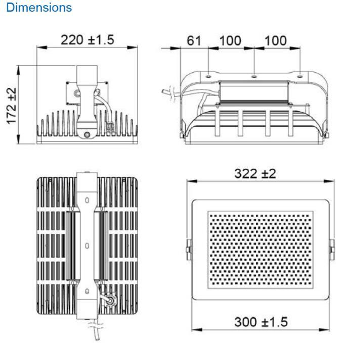
7 Fitting Assemble the LED luminaire with at least two stainless steel fastening screws with a diameter of 6 mm. The drilling distance between the holes is 200 mm. Then connect the existing, flexible connection cable for mains supply on the product to the existing power supply on site, protected in an external power distribution box (not included), with at least the same protection type (IP66) as the product, in accordance with the following illustration. Cable end sleeves should be used with multicore flexible cables. For the connection terminal, we recommend using a 3 pole, insulated connector from the WAGO 294 series for a nominal cross section of 2.5 mm² and a nominal voltage of at least 500 V, meeting the VDE directives 0700 (EN ), VDE 0613 (EN ) and VDE 0711 (EN ) for use in devices and lights up to 24 A. After the LED luminaire has been aligned all the screws must be tightened. Please take care not to damage the power cable when aligning the LED luminaire. Check that the screws are tightly in place once a year. Wiring diagram Neutral [N] (blue) Live [L] (brown or black) Grounding [PE] (yellow/green) 7


8 Assembly instructions for twin holder As a variant for the assembly of luminaires from the Lucid arena pro series its possible to combine two luminaires. For this we offer the twin holder with the item No By buying the Twin holder you will receive following parts: 1 x holder Twin stainless steel rust-free - material x screws M6 x 20/DIN x washers Ø 6,4 / DIN 125, Form A 2 x self-locking nuts, DIN 985, A2 Assembly the Twin holder 1. Take two single LED luminaires out of the box and dismantle the assembly bracket. Do not discard the bracket and screws. 2. Fix the respective LED luminaire to the Twin holder using the screws provided. Please observe the correct sequence: - Spacer - "Twin" holding bracket - small washer - Circlip - Fastening screw 3. Screw the assembly bracket onto the Twin holder using the assembly material provided (screw packaging) Assembly work may only be carried out by expert personnel. 8

9 Temperature measuring point (tc) The maximum temperature of 80 C at the marking shown in the illustration may not be exceeded. By maintaining the maximum temperature at the tc position it is ensured that components will become hotter than permitted. When the temperature gets too high, sufficient cooling must be provided or the luminaire must be switched off. Temperaturmesspunkt (tc) 9
10 Maintenance, care and cleaning This product requires no maintenance and so does not contain any components which can be checked or replaced by the user. The light source in the luminaires cannot be replaced. In the event of damage, the complete light unit must be replaced. The product is fitted with appropriate safety precautions, which show unauthorised opening (safety screws). In the event of unauthorised opening of the device or removal of the type plate, any guarantee rights will be invalidated. We recommend carrying out regular checks of the screws and the cabling, as well as a visual inspection of the housing and the diffuser for penetration by foreign bodies or superficial damage. During maintenance, the product should be disconnected from the power supply and steps take to ensure it cannot be switched on again accidentally. We recommend cleaning with a damp, soft, lint-free cloth. Do not use abrasive sponges or aggressive cleaners. During cleaning, the product should be disconnected from the power supply and steps take to ensure it cannot be switched on again accidentally. Please note the general safety instructions in the chapter INSTALLATION. Disposal The Lucid arena pro has been developed and manufactured using high-quality materials and components. The symbol means that this product falls under the European directive 2002/96/EG gilt. Please familiarise yourself with the relevant directives relating to the separate collection of old electric and electronic equipment in your country. Please observe the applicable regulations in your country, and do not dispose of disused equipment in domestic waste. Proper disposal of your old devices protects the environment and people from potential negative consequences and contributes towards conserving valuable resources. 10


11 Technical data Lucid arena pro 120 / 118 W 11
12 12

13 Technical data Lucid arena pro / 115 W 13
14 14
15 Guarantee period 1. The guarantee period is 2 years, where an extension to the guarantee was not agreed for an extra fee at the time of purchase. This starts when the product is delivered to the end user. Any claims under guarantee must be made in writing. 2. To validate a guarantee claim, the receipt must be presented, on which the delivery or purchase data is clearly visible. In the event of a claim under guarantee, the device should be sent to your specialist retailer or to the following address: LIGHTS 4 Europe GmbH & Co. KG (in the following LIGHTS ) Gaildorfer Str. 6 D Backnang info@lights.de All design, material and manufacturing faults are covered by the guarantee. 3. The guarantee excludes any faults or deficiencies relating to the following points: a) Failure to follow the operating and safety instructions. b) Natural wear and tear. c) External factors such as transport damage, damage caused by impact, shock or over heating, as well as chemical or electro-chemical factors such as those caused by water, acids or improper use. d) Repairs or alterations carried our by non-authorised third parties. e) Use of unsuitable accessories. f) Unauthorised opening of the housing g) Removal of the type plate 4. The following are also excluded: Damage caused by improper handling, fitting or maintenance of the luminaires (see fitting instructions), damage caused by excessive force, fire, vandalism or accidental damage. 5. LIGHTS will resolve any faults within the guarantee period in consultation with the specialist retailer. This will take the form either of a repair of replacement of the component in question. Parts removed become the property of LIGHTS. Any further claims, of any kind, in particular claims for damages are excluded. 6. The following are excluded from the guarantee: a) Costs for removal / fitting of the faulty or repaired luminaires b) Costs for sending back the faulty luminaires 7. LED luminaire from LIGHTS are subject to ongoing development with regard to technical progress. For this reason, in the event of a repair or a replacement, the design of the repaired or replaced light may not correspond to the original design of the light subject to the claim, but it may be of equal or higher quality in terms of its properties and features. LIGHTS reserves the right to change guarantee periods, fixed price arrangements and conditions without prior notice. However, guarantees with a valid registration before the time of the change remain unaffected by this. LIGHTS reserves the right to make the final decision with regard to the validity of a guarantee claim. 15
16 Legal notices These operating instructions contain the information required for appropriate use. Knowledge and observance contained in these operating instructions are a condition of safe use and for safety in operation. These operating instructions cannot consider every possible application. The LED luminaires are intended for use indoors. In addition, we would like to point out that the contents of these operating instructions are not part of, or represent a change to, a prior or existing agreement, consent or legal relationship. The operating instructions contain information, which is copyright protected. Production of photocopies, or translations into another language, are not allowed without prior written permission from LIGHTS 4 Europe GmbH & Co. KG - Germany. LED-Luminaire and light sources from LIGHTS 4 Europe GmbH & Co. KG are subject to ongoing development with regard to technical progress. 16
Operation, installation and service instructions. Lucid nova pro LED luminaire
 Operation, installation and service instructions Lucid nova pro LED luminaire Please read these instructions before installing the luminaires, using them for the first time, storage or handling. These
Installation manual plugs and connectors with screw connection (16/32 A)
") EN Installation manual plugs and connectors with screw connection (16/32 60003213 Issue 04.2016 2016-04-01 Table of contents 1 About this manual 3 1.1 Structure of the warnings 3 1.2 Symbols used 4 1.3
EN Installation manual plugs and connectors with screw connection (16/32 60003213 Issue 04.2016 2016-04-01 Table of contents 1 About this manual 3 1.1 Structure of the warnings 3 1.2 Symbols used 4 1.3
SolConeX extra-low voltage flange socket
 SolConeX extra-low voltage flange socket Operating instructions Additional languages www.stahl-ex.com Contents 1 General Information...3 1.1 Manufacturer...3 1.2 Information regarding the operating instructions...3
Installation Guide. QBox-V6. Standalone/Spare V6 SDI QBox. Standalone/Spare V6 SDI QBox. Part No. A
 Installation Guide Standalone/Spare V6 SDI QBox QBox-V6 Standalone/Spare V6 SDI QBox Part No. A9009-0004 EN www.autocue.com Copyright 2017 All rights reserved. Original Instructions: English All rights
icore Kiosk system Installation Guide
 icore Kiosk system Installation Guide The reproduction, transmission or use of this document or its contents is not permitted without express authority. Offenders will be liable for damages. All rights,
PTB 01 ATEX 2064 U, IECEx PTB U. Example / Beispiel / Exemple: Type Operating Instructions
 , Equipment protection fuse with Ex mb II C Gb approval Geräteschutzsicherung mit Zulassung Ex mb II C Gb Fusible de protection d appareil avec homologation Ex mb II C Gb Example / Beispiel / Exemple:
Operating Instructions (Translation) 3. Safety Information. 1. Description. 2. Explosion Protection. Supply module Type 17-21BB-170x
 3. Safety Information. 1. Description. 2. Explosion Protection. Supply module Type 17-21BB-170x") 1. Description The supply module was developed specially for direct mounting in hazardous areas in Zone 1 and 21 and is ATEX-certified. The supply module is a permanently installed piece of electrical
1. Description The supply module was developed specially for direct mounting in hazardous areas in Zone 1 and 21 and is ATEX-certified. The supply module is a permanently installed piece of electrical
SolConeX Wall-Mounted Socket, 16 A
 SolConeX Wall-Mounted Socket, 16 A Operating instructions Additional languages www.stahl-ex.com General Information Contents 1 General Information...2 1.1 Manufacturer...2 1.2 Information Regarding the
Model 2460-KIT. Screw Terminal Connector Kit. Description / September 2014 *P * 1
 Keithley Instruments 28775 Aurora Road Cleveland, Ohio 44139 1-800-935-5595 http://www.keithley.com Model 2460-KIT Screw Terminal Connector Kit Description The Model 2460-KIT Screw Terminal Connector Kit
Operating Manual / IEC. Explosion-Proofed Junction Boxes, Polyester. Wallücker Bahndamm 7 DE Kirchlengern
 Operating Manual / IEC Explosion-Proofed Junction Boxes, Polyester Wallücker Bahndamm 7 DE- 32278 Kirchlengern Tel.: +49 5223 49107-0 Fax: +49 5223 49107-28 info@multi-box.com www.multi-box.com Contents
Operating instructions. Switching amplifier DN0210 DN / / 2015
 Operating instructions Switching amplifier DN0210 DN0220 UK 80011079 / 00 01 / 2015 Contents 1 Preliminary note...4 1.1 Symbols used...4 1.2 Warning signs used...4 2 Safety instructions...5 2.1 General...5
Fog machine PT Users Manual
 Fog machine PT-1500 Users Manual Table of content 1. Safety instructions... 3 1.1. For safe and efficient operation... 3 2. Intended use of the device... 4 2.1. Overhead installation... 5 2.2. Electrical
HST -S1 Switching element (Translation of Original Manual)
") Installation and Operating Manual for Components HST -S1 Switching element (Translation of Original Manual) HST-S1 Ident.-No.: 10222 HST-S1 Ident.-No.: 10228 HST-S1 Ident.-No.: 10223 HST-S1 Ident.-No.:
Installation and Operating Manual for Components HST -S1 Switching element (Translation of Original Manual) HST-S1 Ident.-No.: 10222 HST-S1 Ident.-No.: 10228 HST-S1 Ident.-No.: 10223 HST-S1 Ident.-No.:
PV Module Installation Instructions
 Name 1601A Page 1 / 8 Name 1601A Page 2 / 8 1 Introduction Thanks for purchasing PV modules of HT SOLAR ENERGY JOINT STOCK COMPANY This manual refers to PV modules manufactured and sold by HT Turkey. This
HST -TZ1 Guard-locking mechanism (Translation of Original Manual)
") Installation and Operating Manual for Components HST -TZ1 Guard-locking mechanism (Translation of Original Manual) HST-TZ1 Ident.-No.: 10234 HST-TZ1 Ident.-No.: 10236 HST-TZ1 Ident.-No.: 10235 HST-TZ1
Installation and Operating Manual for Components HST -TZ1 Guard-locking mechanism (Translation of Original Manual) HST-TZ1 Ident.-No.: 10234 HST-TZ1 Ident.-No.: 10236 HST-TZ1 Ident.-No.: 10235 HST-TZ1
This 4200-RM Rack Mount Kit is for installation in 4200-CAB series cabinets only.
 Keithley Instruments, Inc. 28775 Aurora Road Cleveland, Ohio 44139 (440) 248-0400 Fax: (440) 248-6168 www.keithley.com Model 4200-RM Rack Mount Kit Packing List Introduction NOTE This 4200-RM Rack Mount
Operating Instructions
 TPS S1 AC in DC out Translation of the original instructions TPS 110-400 Mains pack Operating Instructions PT 0199 BEN/C (1010) EN Table of contents Table of contents 1 About this manual...............................................
HST -M1 Switching element with locking mechanism (Translation of Original Manual)
") Installation and Operating Manual for Components HST -M1 Switching element with locking mechanism (Translation of Original Manual) HST-M1 Ident. No.: 10213 HST-M1 Ident. No.: 10219 HST-M1, pictured Ident.
Installation and Operating Manual for Components HST -M1 Switching element with locking mechanism (Translation of Original Manual) HST-M1 Ident. No.: 10213 HST-M1 Ident. No.: 10219 HST-M1, pictured Ident.
Operating manual. Diagnostic adapter VAS Operating manual Diagnostic adapter VAS Client documentation Revision: 00 Version: 05/2018
 Operating manual Diagnostic adapter VAS 611 009 CAR-connect GmbH info@car-connect.cc www.car-connect.cc Page 1 of 11 Imprint Title: Operating manual of diagnostic adapter VAS 611 009 Manufacturer: CAR-connect
Operating instructions AS-i SmartLine module AC3200 AC /00 06/2016
 Operating instructions AS-i SmartLine module AC3200 AC3201 80237876/00 06/2016 Contents 1 Preliminary note...3 1.1 Symbols used...3 1.2 Warnings used...3 2 Safety instructions...3 2.1 General...3 2.2 Target
POCKET MULTIMETER Model No: MM18
 INSTRUCTIONS FOR: POCKET MULTIMETER Model No: MM18 Thank you for purchasing a Sealey product. Manufactured to a high standard this product will, if used according to these instructions and properly maintained,
Operating instructions. Speed monitor D / / 2014
 Operating instructions Speed monitor D200 80005257 / 00 05 / 2014 Contents 1 Preliminary note...4 1.1 Symbols used...4 1.2 Warning signs used...4 2 Safety instructions...5 2.1 General...5 2.2 Target group...5
1 Channel Strobe Controller ORDERCODE 40226
 1 Channel Strobe Controller ORDERCODE 40226 Congratulations! You have bought a great, innovative product from Showtec. The Showtec Strobe Controller brings excitement to any venue. Whether you want simple
Large Police Light 100W ORDERCODE 80361
 Large Police Light 100W ORDERCODE 80361 Congratulations! You have bought a great, innovative product from Showtec. The Showtec Large Police Light brings excitement to any venue. You can rely on Showtec,
VFI RTG PDU 6-10K. Installation and user manual. Service and support: Call your local service representative
 VFI RTG PDU 6-10K Installation and user manual Service and support: Call your local service representative SAFETY INSTRUCTIONS SAVE THESE INSTRUCTIONS. This manual contains important instructions that
Model 8020-STC. Kelvin Standard Triaxial Connector Card. Description / October 2014 *P * 1
 Keithley Instruments 28775 Aurora Road Cleveland, Ohio 44139 1-800-935-5595 http://www.keithley.com Model 8020-STC Kelvin Standard Triaxial Connector Card Description The Model 8020-STC Kelvin Standard
HV-CS kv Edge Mount Triaxial Jack
 Keithley Instruments 28775 Aurora Road Cleveland, Ohio 44139 1-800-935-5595 http://www.tek.com/keithley HV-CS-1589 3 kv Edge Mount Triaxial Jack Installation Information Description The Keithley Instruments
HST -M2 Switching element with locking mechanism (Translation of Original Manual)
") Installation and Operating Manual for Components HST -M2 Switching element with locking mechanism (Translation of Original Manual) HST-M2 Ident.-No.: 10214 HST-M2 Ident.-No.: 10626 HST-M2 Ident.-No.: 10218
Installation and Operating Manual for Components HST -M2 Switching element with locking mechanism (Translation of Original Manual) HST-M2 Ident.-No.: 10214 HST-M2 Ident.-No.: 10626 HST-M2 Ident.-No.: 10218
Operating Manual -ENGLISH- Page 1 KWG-ISO
 Page 1 KWG-ISO Operating manual English- Status May 2013 Page 2 Manufacturer address KW-Generator GmbH & Co.KG Bänglesäcker 24 73527 Schwäbisch-Gmünd / Lindach Phone: +49 (0) 7171 104 17 0 Fax: +49 (0)
Operating instructions Evaluation system for flow sensors VS / / 2013
 Operating instructions Evaluation system for flow sensors VS3000 7097 / 0 07 / 203 Contents Preliminary note...2 2 Safety instructions...3 3 Function and features... Mounting.... Mounting of the sensors...
MBE Mounts and Adapters
 MBE Mounts and Adapters MBE Series en Installation Guide MBE Mounts and Adapters Table of Contents en 3 Table of Contents 1 Important safety instructions 4 2 MBE Series Mounts and Adapters 6 2.1 Unpacking
TA18 active subwoofer. user manual
 TA18 active subwoofer user manual Musikhaus Thomann e.k. Treppendorf 30 96138 Burgebrach Germany Telephone: +49 (0) 9546 9223-0 email: info@thomann.de Internet: www.thomann.de 30.11.2011 Table of contents
STR-3 STANDARD 3-PHASE 230 VAC TRANSFORMER CONTROLLER. Mounting and operating instructions
 STANDARD 3-PHASE 230 VAC TRANSFORMER CONTROLLER Mounting and operating instructions Table of contents SAFETY AND PRECAUTIONS 3 PRODUCT DESCRIPTION 4 ARTICLE CODES 4 INTENDED AREA OF USE 4 TECHNICAL DATA
Model 8020-KHV. Kelvin Keithley Triaxial Connector Card. Description / October 2014 *P * 1
 Keithley Instruments 28775 Aurora Road Cleveland, Ohio 44139 1-800-935-5595 http://www.keithley.com Model 8020-KHV Kelvin Keithley Triaxial Connector Card Description The Model 8020-KHV Keithley HV Connector
english S-5EC Potentiometer 5-step Operating Instructions Keep for reference! L-BAL-E265-GB 1608 Index 002
 S-5EC english Potentiometer 5-step Operating Instructions Keep for reference! Content 1 General notes............................................ 3 1.1 Structure of the operating instructions....................
LED Pixel Rail 40 RGB LED strip. user manual
 LED Pixel Rail 40 RGB LED strip user manual Musikhaus Thomann Thomann GmbH Hans-Thomann-Straße 1 96138 Burgebrach Germany Telephone: +49 (0) 9546 9223-0 E-mail: info@thomann.de Internet: www.thomann.de
DuoFern Multiple Wall Controller
 DuoFern Multiple Wall Controller 9494-1 Instruction manual for the electrical connection and for commissioning Item no. 3250 19 74 / Type: 9494-1 (surface-mounted with battery) VBD 663-2 (12.16) Dear Customer,
BW-108. Building Wash BW-108. User Guide. Advanced LED Technology
 Building Wash User Guide Advanced LED Technology TABLE OF CONTENTS 1. Safety Instruction 2. Technical Specification 3. Change Beam Angle 4. Main Function 5. How To Control The Unit 6. Troubleshooting 7.
The following symbols are used to show dangerous operation or handling. Make sure you understand them before reading the guide.
 Safety Instructions Before use Thank you very much for purchasing this product. This product is an interface box called "Connection & Control Box" for EPSON short throw projectors. For your safety, read
MDM 011-Z1 Regen Resistor
 MDM 011-Z1 Regen Resistor Date of creation: 10.04.2017 Version date: 10.04.2017 Article number: 09-402-011-Z1-E Publisher: SIGMATEK GmbH & Co KG A-5112 Lamprechtshausen Tel.: 06274/4321 Fax: 06274/4321-18
Model 2657A-LIM-3 LO Interconnect Module
 Keithley Instruments, Inc. 28775 Aurora Road Cleveland, Ohio 44139 1-888-KEITHLEY http://www.keithley.com Model 2657A-LIM-3 LO Interconnect Module User's Guide Description The Model 2657A-LIM-3 LO Interconnect
XCU Fusion. 316L stainless-steel dual imager camera. Installation Manual
 XCU Fusion 316L stainless-steel dual imager camera Installation Manual Note: To ensure proper operation, please read this manual thoroughly before using the product and retain the information for future
Model 7705 Control Module
 www.keithley.com Model 7705 Control Module User s Guide PA-696 Rev. D / October 2006 A G R E A T E R M E A S U R E O F C O N F I D E N C E Safety Precautions The following safety precautions should be
LASERMET SLIMJIM LED SIGN INSTRUCTION MANUAL LEDS-SJ XXX
 LASERMET SLIMJIM LED SIGN INSTRUCTION MANUAL LEDS-SJ 00843-00-XXX 00843-53-000 Page 1 of 11 Issue 3 2 January 2013 Lasermet SlimJim Illuminated Sign Instruction Manual Contents Introduction... 4 Installation...
IPCB42501 / IPCB42551
 IPCB42501 / IPCB42551 Installation manual Version 03/2017 IPCB42501 IPCB42551 English translation of the original German user manual. Retain for future reference. uk Introduction Dear Customer, Thank you
TPC25 active crossover. user manual
 TPC25 active crossover user manual Musikhaus Thomann Thomann GmbH Hans-Thomann-Straße 1 96138 Burgebrach Germany Telephone: +49 (0) 9546 9223-0 E-mail: info@thomann.de Internet: www.thomann.de 25.09.2017,
Promopar ORDERCODE 30120
 Promopar ORDERCODE 30120 Congratulations! You have bought a great, innovative product from Showtec. The Showtec Promopar brings excitement to any venue. You can rely on Showtec, for more excellent lighting
D610H, D610H MKII, D610S, D610T dimmer pack. user manual
 D610H, D610H MKII, D610S, D610T dimmer pack user manual Musikhaus Thomann Thomann GmbH Hans-Thomann-Straße 1 96138 Burgebrach Germany Telephone: +49 (0) 9546 9223-0 E-mail: info@thomann.de Internet: www.thomann.de
LED SPIDER MOVING HEAD LIGHT
 LED SPIDER MOVING HEAD LIGHT MJ-1031C (4IN1) INSTRUCTION MANUAL Thank you for choosing our LED spider moving head light. For the sake of your safety, Please read and follow these instructions carefully
Model 2380 Rack-Mount Kit
 Keithley Instruments 28775 Aurora Road Cleveland, Ohio 44139 1-800-935-5595 http://www.tek.com/keithley Model 2380 Rack-Mount Kit Installation Instructions Introduction The Model 2380 Fixed Rack-Mount
...easy to operate with ProHomeIPC. IP-Kamera OC 800 Quick Start Guide
 ...easy to operate with ProHomeIPC IP-Kamera OC 800 Quick Start Guide Do you need detailed descriptions on how to use the app and operate the camera? Visit us at www.olympia-vertrieb.de Or scan this QR
High Power Electronic Gear Installation and operation Guide
 High Power Electronic Gear Installation and operation Guide 96268731 GT 1 KW 230-240 V HQITS-S DGE CLI WI SC 96267936 GT 2 KW 230-240 V HO/HF DGE CLI WI SC IP21 IP21 electronical gear for 1 and 2 kw HIT-DE
Gobo Projector XP 80W
 Gobo Projector XP 80W User Manual Order code: EQLED084 Safety advice WARNING FOR YOUR OWN SAFETY, PLEASE READ THIS USER MANUAL CARE- FULLY BEFORE YOUR INITIAL START-UP! Before your initial start-up, please
CVU-200-KIT. 200 V Bias Tee Kit. Description. Parts list / October 2014 *P A* 1
 Keithley Instruments 28775 Aurora Road Cleveland, Ohio 44139 1-800-935-5595 http://www.keithley.com CVU-200-KIT 200 V Bias Tee Kit Description The CVU-200-KIT Bias Tee Kit consists of three 2600-RBT-200
HST -TS1 Guard-locking mechanism (Translation of Original Manual)
") Installation and Operating Manual for Components HST -TS1 Guard-locking mechanism (Translation of Original Manual) HST-TS1 Ident.-No.: 10250 HST-TS1 Ident.-No.: 10252 HST-TS1 Ident.-No.: 10251 HST-TS1
Installation and Operating Manual for Components HST -TS1 Guard-locking mechanism (Translation of Original Manual) HST-TS1 Ident.-No.: 10250 HST-TS1 Ident.-No.: 10252 HST-TS1 Ident.-No.: 10251 HST-TS1
- ELV OVERVIEW. InstallationGuide SUPPLIED PARTS RELATED PARTS. Brackets Fixtures. Other. 1 of 9 IG-STR9-ELV
 OVERVIEW The STR9 ELV is a long run, low power, linear surface mount LED lighting system designed for exterior architectural lighting applications. This guide contains important information on planning
DC-D2212R / DC-D2212WR
 Network Camera Quick Guide / DC-D2212WR Powered by Safety Precautions WARNING RISK OF ELECTRIC SHOCK DO NOT OPEN WARNING: TO REDUCE THE RISK OF ELECTRIC SHOCK, DO NOT REMOVE COVER (OR BACK). NO USER-SERVICEABLE
B63/ NS MS. EtherNet/IP LINK
 3 609 929 B63/ IMenip 2008-09 NS MS EtherNet/IP LINK 3 609 929 B63/2008-09 IMenip Bosch Rexroth AG 15/76 Table of Contents About this document................. 16 General safety instructions............
PKP Prozessmesstechnik GmbH. Borsigstrasse 24. D Wiesbaden-Nordenstadt. Tel: / Fax: / Operating manual PSA06
 PKP Prozessmesstechnik GmbH Borsigstrasse 24 D-65205 Wiesbaden-Nordenstadt Tel: 06122 / 7055-0 Fax: 06122 / 7055 50 Operating manual PSA06 Electronical pressure switch Content Page 19-34 1. Foreword 19
Model 2600B-PM V Protection Module with 1 A Clamp. Description / April 2015 *PPA * 1
 Keithley Instruments 28775 Aurora Road Cleveland, Ohio 44139 1-800-935-5595 http://www.keithley.com Model 2600B-PM-1 200 V Protection Module with 1 A Clamp Description The Model 2600B-PM-1 200 V Protection
LED W RGBA User Manual
 LED- 245-1W RGBA User Manual Please read the instructions carefully before use CONTENTS 1. Safety Instructions...2 2. Technical Specifications...3 3. How To Set The Unit...4 3.1 Control Panel...4 3.2 Main
TA12 full-rangespeaker. user manual
 TA12 full-rangespeaker user manual Musikhaus Thomann e.k. Treppendorf 30 96138 Burgebrach Germany Telephone: +49 (0) 9546 9223-0 email: info@thomann.de Internet: www.thomann.de 30.11.2011 Table of contents
Weathersafe Vision. Installation & Operating Instructions
 Weathersafe Vision Installation & Operating Instructions IP66 Products covered by these instructions 1 TGVL01 TGVL02 TGVL03 TGVL05 TGV101N TGV201N TGV104N Single Gang 2-Way Switch [SP] 10AX (Fluorescent
DC-D4213RX DC-D4213WRX
 Network Camera Quick Guide DC-D4213RX DC-D4213WRX Powered by Safety Precautions WARNING RISK OF ELECTRIC SHOCK DO NOT OPEN WARNING: TO REDUCE THE RISK OF ELECTRIC SHOCK, DO NOT REMOVE COVER (OR BACK).
LED Shoe Box light FEATURES AND BENEFITS: ORDERING MATRIX: LED SHOE BOX LIGHT:
 ASD slim shoe box lights use up to 8% less energy than metal halide or high pressure sodium lights and put out a much nicer light. Lights up instantly, no warm-up period needed, type III distribution,
Orbital smart Tunable Downlight
 Commissioning The ceiling surface must be flat and smooth to ensure a good fit. Push the spring clips upwards and fit into the ceiling hole. See Fig 1. Push the unit up until firmly in position, ensuring
Operating instructions. Standstill monitor A / / 2011
 Operating instructions Standstill monitor A300 UK 1 2 3 4 5 6 7 8 7390337 / 01 02 / 2011 1 2 3 4 5 6 7 8 switchpoint min max pulse/min power Made in Germany ifm electronic gmbh D 45127 Essen func. I II
LED Colour Flood 10W / 30W RGB LED floodlight. user manual
 LED Colour Flood 10W / 30W RGB LED floodlight user manual Musikhaus Thomann e.k. Treppendorf 30 96138 Burgebrach Germany Telephone: +49 (0) 9546 9223-0 E-mail: info@thomann.de Internet: www.thomann.de
NXT4 Three phase meter for commercial, industrial and advanced residential applications
 EMH metering GmbH & Co. KG Neu-Galliner Weg 1 19258 Gallin GERMANY Tel. +49 38851 326-0 Fax +49 38851 326-1129 E-Mail info@emh-metering.com Web www.emh-metering.com Tel. +49 38851 326-1930 (Technical Support)
D-Pack 6 Classic ORDERCODE 50315
 D-Pack 6 Classic ORDERCODE 50315 Congratulations! You have bought a great, innovative product from Showtec. The Showtec D-Pack 6 Classic brings excitement to any venue. Whether you want simple plug-&-play
SOLARIMMERSION IV Advanced Installation Manual v1.9
 SOLARIMMERSION IV Advanced Installation Manual v1.9 1 Contents 1. Overview 2. Technical Specifications 3. Installation Mounting Electrical Installation Clamp Installation Wiring Diagrams 4. Installation
HD40H(X) Performance Series Camera. User Guide
 Performance Series Camera. User Guide") HD31H(X) HD30H(X) HD40H(X) Performance Series Camera User Guide Document 1 2 HD40H(X)/HD30H(X)/HD31H(X) Camera User Guide Thank you for purchasing our product. If there are any questions, or requests,
HD31H(X) HD30H(X) HD40H(X) Performance Series Camera User Guide Document 1 2 HD40H(X)/HD30H(X)/HD31H(X) Camera User Guide Thank you for purchasing our product. If there are any questions, or requests,
MANUAL. ENGLISH Showtec PSA-161 Ordercode: Highlite International B.V. Vestastraat EX Kerkrade the Netherlands
 MANUAL ENGLISH Showtec PSA-161 V1 Highlite International B.V. Vestastraat 2 6468 EX Kerkrade the Netherlands Table of contents Warning... 2 Safety Instructions... 2 Operating Determinations... 4 Connection
Installation and safety instructions for devices for conveying air/gas mixtures
 The device type and date of manufacture (week/year) can be found on the device rating plate. In the event of any queries about the device, please quote all the details given on the rating plate. For further
ILUMEN PID SOLUTION INDOOR OUTDOOR ILUMEN PIDBOX MINI INSTALLATION MANUAL. Ilumen PIDbox mini Version 1.5
 ILUMEN PID SOLUTION ILUMEN PIDBOX MINI INSTALLATION MANUAL INDOOR OUTDOOR Ilumen PIDbox mini Version 1.5 1 TABLE OF CONTENT 1 Information on this manual... 3 1.1 Validity... 3 1.2 Target group... 3 1.3
When any of the following symbols appear, read the associated information carefully. Symbol Meaning Description
 Uni-I/O Modules Installation Guide UID-0808R, UID-0808T, UID-1600,UID-0016R, UID-0016T Uni-I/O is a family of Input/Output modules that are compatible with the UniStream control platform. This guide provides
Model No. ET-JPF200BE
 Operating Instructions Floor Stand Kit Commercial Use Model No. ET-JPF200BE ET-JPF200WE ENGLISH FRANÇAIS ESPAÑOL DEUTSCH ITALIANO * The above illustration is of this product mounted to an optional projector.
RCD Fused Connection Unit Model: RCD10WPV. RCD Double Sockets Models: RCD05WAV, RCD06WPV, RCD07MAV, RCD08MPV. Installation & Operating Instructions
 RCD Fused Connection Unit Model: RCD10WPV RCD Double Sockets Models: RCD05WAV, RCD06WPV, RCD07MAV, RCD08MPV Installation & Operating Instructions General The Timeguard range of RCDs provides protection
Installation Instructions
 50ES, 50EZ, 50GL, 50GS, 50GX, 50JS, 50JX, 50JZ, 50SD, 50SZ, 50VL, 50VT, 50XP, 50XZ 601A, 602A, 602B, 604A, 604B, 604D, 607C, 701A, 702A, 702B, 704A, 704B, 704D, 707C PA1P, PA2P, PA3P, PH1P, PH2P, PH3P
PHOS mini OPERATING INSTRUCTIONS
 PHOS mini OPERATING INSTRUCTIONS TABLE OF CONTENTS Safety Instructions...4 Electrical Safety... 4 Burns and Fire Safety... 5 Lamp Safety...5 Safety during installation and operation... 6 Technical Overview
VDLPROM5 SET WITH DMX CONTROL BOX + 4 COLOUR CHANGERS
 SET WITH DMX CONTROL BOX + 4 COLOUR CHANGERS 1. Introduction & Features Thank you for buying the! Please read the manual carefully before bringing this device into service. This set contains 4 DMX-controlled
RТTH DUAL ROOM SWITCH
 DUAL ROOM SWITCH FOR TEMPERATURE AND RELATIVE HUMIDITY Mounting and operating instructions Table of contents SAFETY AND PRECAUTIONS PRODUCT DESCRIPTION ARTICLE CODES INTENDED AREA OF USE TECHNICAL DATA
Operating manual. GTL - Configuration tool. Please keep the manual for future use.
 Operating manual GTL - Configuration tool Please keep the manual for future use. V1.00-01 GREISINGER Electronic GmbH Hans-Sachs-Str. 26 93128 Regenstauf Germany Fon +49(0)9402-9383-0 Fax +49(0)9402-9383-33
10W LED PIN SPOT. User Manual LED-PS10D W. Innovation, Quality, Performance. Professional Entertainment Technology 11-
 Innovation, Quality, Performance 11-10W LED PIN SPOT LED-PS10D W User Manual Professional Entertainment Technology TABLE OF CONTENTS 1. Safety Instruction 2. Technical Specification 3. Installation 4.
2260B-RMK-Series Rack Mount Kit
 Keithley Instruments, Inc. 28775 Aurora Road Cleveland, Ohio 44139 1-888-KEITHLEY http://www.keithley.com Assembly and Mounting Instructions Introduction The 2260B-RMK-Series Rack Mount Kit is suited for
LIGHT BRICK - 12 X 3W TRI-COLOUR
 www.prolight.co.uk LIGHT BRICK - 12 X 3W TRI-COLOUR (Order code: LEDJ162) USER MANUAL Safety WARNING FOR YOUR OWN SAFETY, PLEASE READ THIS USER MANUAL CAREFULLY BEFORE YOUR INITIAL START-UP! CAUTION! Keep
GRP Flameproof Visual Signal Xenon or Steady LED
 GRP Flameproof Visual Signal Xenon Operating instructions Additional languages www.stahl-ex.com General Information Contents 1 General Information...2 1.1 Manufacturer...2 1.2 Information regarding the
Original operating instructions Fail-safe inductive sensor GF711S / / 2013
 Original operating instructions Fail-safe inductive sensor GF7S 8528 / 5 / 23 Contents Preliminary note...3. Explanation of symbols...3 2 Safety instructions...4 2. Safety-related requirements regarding
Portable Sampler MAXX TP5 W / P / C
 Portable Sampler MAXX TP5 W / P / C TP5 W TP5 P TP5 C (pic. with optional Box) TP5 C-P-W 0250030E Oct 2015 MAXX GmbH, 2015. All rights reserved. Printed in Germany Access code for programming and settings
Installation instructions RF-identification system with integrated AS-i slave DTSLF / / 2010
 Installation instructions RF-identification system with integrated AS-i slave UK DTSLF 704153 / 07 04 / 2010 Inhalt 1 Preliminary note...4 1.1 Symbols used...4 2 Safety instructions...4 2.1 General...4
Operating Manual. icam100
 icam100 This page is intentionally left blank. Document Number 302803 (See Last Page for Revision Details) 2006 Extronics Limited. This document is Copyright Extronics limited. Extronics reserve the right
Model 2380 Rack-Mount Kit
 Keithley Instruments 28775 Aurora Road Cleveland, Ohio 44139 1-800-935-5595 http://www.tek.com/keithley Model 2380 Rack-Mount Kit Installation Instructions Introduction The Model 2380 Fixed Rack-Mount
650/1000 Fresnel 650/1000 PC 300/500 Antihalo 300/500 Fresnel theatre spotlight. user manual
 650/1000 Fresnel 650/1000 PC 300/500 Antihalo 300/500 Fresnel theatre spotlight user manual Musikhaus Thomann Thomann GmbH Hans-Thomann-Straße 1 96138 Burgebrach Germany Telephone: +49 (0) 9546 9223-0
When any of the following symbols appear, read the associated information carefully. Symbol Meaning Description
 Uni-I/O Wide Modules Installation Guide UID-W1616R, UID-W1616T Uni-I/O Wide is a family of Input/Output modules that are compatible with the UniStream control platform. Wide Modules are 1.5 times as wide
Original operating instructions Fail-safe inductive sensor GI711S / / 2010
 Original operating instructions Fail-safe inductive sensor GI7S 704583 / 0 06 / 200 Contents Preliminary note 3. Explanation of symbols 3 2 Safety instructions 4 2. Safety-related requirements regarding
Flexoled FTP3HP RGB LED DMX Driver
 Flexoled FTP3HP RGB LED DMX Driver User Manual + 12-24V DMX INPUT DMX OUTPUT DC IN (12A MAX) DMX ADDRESS & DIMMER SETTINGS SWITCH 10 11 12 DMX MODE DIMMING MODE BUILT-IN MODE LOAD 4A PER CHANNEL (12A MAX)
Table of contents 2 / 8
 Manual Speaker SM5A Table of contents 1. Safety instructions... 3 1.1. Instructions for a safe and efficient operation... 3 1.2. Further safety instructions... 4 1.3. Designated use... 4 2. Introduction...
CVU-3K-KIT. 3 kv Bias Tee Kit. Description. Parts list / October 2014 *P * 1
 Keithley Instruments 28775 Aurora Road Cleveland, Ohio 44139 1-800-935-5595 http://www.keithley.com CVU-3K-KIT 3 kv Bias Tee Kit Description The CVU-3K-KIT Bias Tee Kit consists of three bias tees for
Operation Manual. Capacitor Boxes adjustable 80 A / 125 A Track, 2,04 μf to 8 μf. Order Number
 Order Number 91008-210-3088444 Capacitor Box 80 A adjustable 2,04 μf to 2,72 μf 91008-210-3088445 Capacitor Box 80 A adjustable 3 μf to 8 μf 91012-210-3101180 Capacitor Box 125 A adjustable 2,04 μf to
INSPECTION CAMERA MODEL NO: CIC2410 OPERATION & SAFETY INSTRUCTIONS PART NO: GC0116
 INSPECTION CAMERA MODEL NO: CIC2410 PART NO: 6470385 OPERATION & SAFETY INSTRUCTIONS GC0116 INTRODUCTION Thank you for purchasing this CLARKE Inspection Camera. Before attempting to use this product, please