JUMO TYA 202 SCR Power Controller in a three-phase economy circuit For the continous control of ohmic-inductive loads
|
|
|
- Adelia Young
- 6 years ago
- Views:
Transcription

1 Data sheet Page 1/17 JUMO TYA 202 SCR Power Controller in a three-phase economy circuit For the continous control of ohmic-inductive loads The JUMO TYA 202 represents a consistent further development of the JUMO power controller technology and switches ohmic-inductive loads in a rotary current economic circuit. The microprocessor controlled power controller displays all parameters in a back-lighted LCD display and is operated using the 4 keys on the front. SCR power controllers are employed where larger resistive and ohmic-inductive loads have to be switched, e.g. in industrial kiln construction and in plastics processing. The SCR power controller comprises two SCRs connected in anti-parallel, the insulated cooling body and the control electronics. SCR power controllers up to a load current of 32 A can either be clipped onto a 35 mm mounting rail or fitted to the wall with a mounting plate. Units with a load current greater than 32A have to be fitted to the wall. The TYA 202 works in burst-firing mode. In burst-firing mode, the phase angle can be cut back for the first half-cycle, for driving transformer loads. Available subordinate controls are U, U 2, I, I 2 and P control. Use of a subordinate control ensures that fluctuations in the supply voltage do not affect the control loop during the control process. It is possible to preset a base load. To avoid high starting or inrush currents, a soft start function is available. The SCR power controllers comply with the operating conditions according to DIN EN Grounding is required in conformity with the regulations of the responsible electrical utility company. Block diagram Setpoint, analog inputs Standard signals: 0(2) 10V, 0(1) 5V or SSR Standard signal: 0(4) 20mA Binary inputs Firing pulse inhibit via floating contact Binary Binäreingang input 1 1 freely frei konfigurierbar configurable Binary input 2 Power supply Power supply Extra code TYA 202 Interfaces PROFIBUS DP or serial RS422/485 USB interface for setup program Master-slave communication LC-Display with white backlighting Load output Actual value output - standard signals Approvals/approval marks (see "Technical data") Binary output for centralized fault signals via relay or optocoupler Typ / Special features k LCD display with info line k Simple configuration of the device via clear text display in the operator's language k Setup program for configuration via USB interface k Transmission of the setup data is also possible without voltage supply to the unit (supply via USB port) k Close installation is possible k Mains load optimization through dual energy management k RS422/485 interface or k PROFIBUS DP for connection to process control systems k Softstart function with Burst-firing k Burst-firing mode k Resistance monitoring and limitation for MoSi 2 heating elements k All versions in protection rating IP20 k Load monitoring for the detection of partial load failure or load short circuit "teach-in" k Integrated diagnosis systems such as rotary-field detection k UL Approval submitted
2 Data sheet Page 2/17 Technical data Voltage supply, load current Code Voltage supply for control electronics = max. load voltage Fan specifications Type /X-0X AC 24V -20%...+15%, Hz AC 24V/30VA 042 AC 42V -20%...+15%, Hz AC 24V/30VA 115 AC 115V -20%...+15%, Hz AC 115V/30VA 230 AC 230V -20%...+15%, Hz AC 230V/30VA 265 AC 265V -20%...+15%, Hz AC 230V/30VA 400 AC 400V -20%...+15%, Hz AC 230V/30VA 460 AC 460V -20%...+15%, Hz AC 230V/30VA 500 AC 500V -20%...+15%, Hz AC 230V/30VA Load current I L rms AC 20, 32, 50, 100, 150, 200, 250A Load type Resistive and resistive/inductive loads Control section power consumption max. 40 VA Analog inputs Control signal 0(4) 20mA R i = 50 Ω 0(2) 10V R i = 25kΩ 0(1) 5V R i = 25kΩ Default set point Via standard signals (current, voltage) or interface value Base load: Output as minimum control value Maximum control value: Output as maximum control value Example P control: P Maximum Output level: 3680 W 3000W mA Base load: 680 W 0 ma 20 ma Base load Control signal Binary inputs Binary input 1, 2 For connection to potential-free contact or optocoupler, voltage proof up to DC 12V Binary outputs, actual value output Relay (changeover contact) without contact suppression Optocoupler output Actual value output switching actions at a contact rating of 3A/230V 50Hz (resistive load) I Cmax = 2mA, U CEOmax = 32V Switched off as standard. For standard signal, voltage: 0 10V, 2 10V, 0 5V to 1 5V For standard signal, current: 0 20mA to 4 20mA (burden max. 500Ω) Depending on the device type, the output of various internal measuring values such as load current, load voltage or power is possible. Thyristor firing request: continous logic (Solid State Relais SSR) setpoint specification Current input (current proof up to 25mA) setpoint specification Voltage input (voltage proof up to DC 32V) The power controller provides the power for the load continuously depending on the default setpoint value. The power controller acts like a switch and provides the power by either switching ON or OFF. The switching level is always in the middle of the selected input range. At 4 to 20mA it is 12mA, at 0 to 10V it is 5V. setpoint specification Binary input1, 2 (voltage proof up to DC 32V) via Interface - possible OFF logic level 0 = 0 to +0,8V; ON logic level 1 = +2 to 3,3V possible
3 Data sheet Page 3/17 General characteristic data Circuit options Operating modes Special features Subordinate control loop Electrical connection Approvals/approval marks - Three-phase economy circuit in master/slave operation - Impulsgruppenbetrieb für ohmsche Last oder Trafolast mit Softstart - Dual energy management - Burst-firing mode with softstart U² control as standard Can be switched over to U, I, I², P control depending on device type For type /X -0X Control and load leads are connected via screw terminals. For type /X -0X Control leads are connected via screw terminals and load leads via cable lugs DIN and DIN46234 or tubular cable lugs. Operating conditions The controller is designed as a panel-mounting device according to: EN , pollution degree 2, overvoltage category Ü III Electromagnetic compatibility According to DIN Emitted interference: Class B Interference resistance: Industrial requirements Protection rating All device types IP20 according to EN Protection rating Protection rating I, with isolated control circuitry for connection to SELV circuits Permissible ambient temperature range Permissible storage temperature range 35 C with forced air cooling (250A controller) 0 45 C with natural air cooling (extended temperature range class 3K3 according to EN ) At higher temperatures, operation with reduced type current is possible. (from 45 C with type current -2%/ C) C (1K5 according to EN ) Cooling - Natural convection up to a load current of 200A - For a load current of 250A, forced convection with built-in ventilator Environmental performance Rel. humidity 85 % annual average, no condensation 3K3 according to EN Installation position Vertical Test voltage According to EN Creepage distances 8 mm between supply current circuit and SELV circuits for type /X -0X mm between supply current circuit and SELV circuits from type /X -0X SELV = Separate Extra Low Voltage (safe low voltage) Case Plastic, flammability class UL94 V0, color: Cobalt blue RAL 5013 Power dissipation The power dissipation can be calculated using the following empirical formula: P v = 2 x (20W + 1.3V x I Load A) Maximum temperature of the 110 C cooling body Type (Load current) 20A 32A 50A 100A 150A 200A 250A Weight approx. 2.2 kg approx. 4.2 kg approx. 5.4 kg approx. 7.6 kg approx. 17 kg approx. 19 kg approx kg Approval mark Testing agency Certificates / certification numbers Inspection basis Valid for c UL us Underwriters Laboratories submitted UL 508 All device Versions
4 Data sheet Page 4/17 Display and measuring accuracy All specifications refer to the controller nominal data. Supply voltage: ± 2,5% Load current: ± 1% Load voltage: ± 1% Power: ± 2% Analog input Voltage/current: ± 1% Analog output Voltage/current: ± 1% Load resistance: ± 2% (for resistive load) Permissible load current depending on the ambient temperature and installation height Load current in A Reduction at a temperature of 45 C: 2 %/kelvin 70 % Note: At a device temperature of 105 C, the load current is reduced for each degree of temperature increase. The power controller current is switched off completely at a device temperature of >115 C T/ C Note: In the case of air cooling, it must be noted that the effectiveness of the cooling is reduced the higher up the device is installed. As a result, the current carrying capacity of the SCR power controller decreases with such a cooler as the installation height increases as shown in the image.

5 Data sheet Page 5/17 Electrical isolation USB Interface Analog input 0(2) to 10 V, 0 to 5 V or SSR Analog input 0(4) to 20 ma AC 350 V AC 350 V PROFIBUS-DP or RS422/485 serial interface Actual value output standard signal Voltage output DC 10 V Binary input 1, 2 floating contact Display and keypad AC 3800 V Voltage supply AC 3800 V Display, operation and connection elements Legend Remark Fig. 1 LED Power (green) is lit when the voltage supply is connected 2 LCD display with white background lighting (96 x 64 pixels). (no LCD display on Slave device) The info line at the bottom of the display indicates current settings and error messages. 3 The LED Fuse (red) is lit when the semi-conductor fuse is blown 4 LED K1 (yellow) fault signal output 5 Keys: Increase value / parameter up Binary output Relay or optocoupler Load connection U1, U2 (1) (2) (3) (4) Decrease value / parameter down Abort / one level back Programming / one level lower (no Keys on Slave device) 6 USB setup interface Konfiguration data is set on the left device and will be transmitted automtaically via 1:1 Patch cable to the right device. 7 Release clip for removing the plastic case (push to the right) (5) (6) (7) (7)
6 Data sheet Page 6/17 Dimensions Type /X-0X-20A-XXX-XXX-XX-25X Type /X-0X-032-XXX-XXX-XX-25X
7 Data sheet Page 7/17 Type /X-0X-050-XXX-XXX-XX-25X Type /X-0X-100-XXX-XXX-XX-25X
8 Data sheet Page 8/17 Type /X-0X-150-XXX-XXX-XX-25X Type /X-0X-200-XXX-XXX-XX-25X, Clearances (all types) k Allow a clearance of 10 cm from the floor. k Allow a clearance of 15 cm from the ceiling. k When fittede next to each other, no spacing between the devices is reqired.
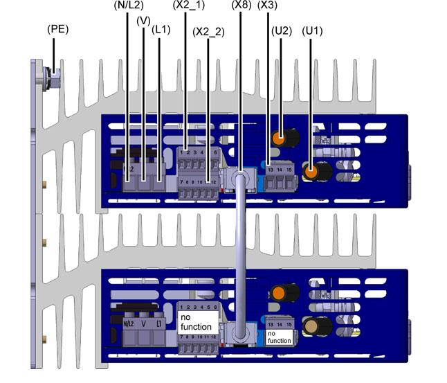
9 Data sheet Page 9/17 Type /X-0X-250-XXX-XXX-XX-25X Maximum tightening torques for screw connections Terminals Version Tightening torque For all types X2_1 numbers 1...6, X2_2 numbers and modbus RS422/485 (Terminals 16, 17, 18, 19 Plug-in screw terminals (slotted screws) 0.25 Nm X3 numbers 13, 14, 15 Plug-in screw terminals (slotted screws) 0.5 Nm Type /X-0X Clamping block U1, U2, N/L2, V, L1 Ground terminal PE: Type /X-0X-032 and type /X-0X U1, U2: Clamping block N/L2, V, L1 Ground terminal PE: Type /X-0X U1, U2: Clamping block N/L2, V, L1 Ground terminal PE: Type /X-0X , /X-0X-200 and Type /X-0X U1, U2: Clamping block N/L2, V, L1 Ground terminal PE: Plug-in screw terminals (recessed head screws) M4 headless setscrew with nut M6 recessed head screws Plug-in screw terminals (slotted screws) M6 headless setscrew with nut M6 hexagon screw, width across flats 10 mm Plug-in screw terminals (slotted screws) M6 headless setscrew with nut M8 hexagon screw, width across flats 13 mm Plug-in screw terminals (slotted screws) M8 headless setscrew with nut 0.6 Nm 3 Nm 5Nm 0.5Nm 5Nm 5Nm 0.5Nm 5Nm 12 Nm 0.5Nm 12 Nm Typ /X-0X X14 numbers 20, 21 Plug-in screw terminals (slotted screws) 0,5Nm

10 Data sheet Page 10/17 Connection diagram The connection diagram contained in the data sheet provides a first information about the connection possibilities. Only use the installation instructions or the operating manual for the electrical connection. The knowledge and the correct technical execution of the safety information/ instructions contained in these documents are prerequisite for installation, electrical connection and commissioning/start-up as well as for safety during operation. Typ /X-0X-20-XXX-XXX-XX-25X Note: Master-Slave connection is already established and device configuration is set (factory setting). The device is ready for connection of the load and the voltage supply. Power section Connection for screw terminals control section/ power section Detail Voltage supply Control electronics (is the same as the max. Load voltage of the ordered Type, see order matrix) L1 N/L2 V V V Protective earth PE PE PE Load connection Fan X14 20, 21 (only types with load current 250A) U1 U2 L1 N/L2 U1 U2 Control section Connection for Screw terminal X2_1 Detail Setpoint value input current I x 1 2 Setpoint value input voltage 3 (GND) 4 Output DC 10V fixed voltage 5 Ground potential 6 (GND) + U x 3 4 5k S E A Example for external manual mode via potentiometer
 OFF logic level 0 = 0 to +0,8V; ON logic level 1 = +2 to 3,3V Binary input2 (voltage proof up to DC 32V) OFF logic level 0 = 0 to +0,8V; ON logic level 1 = +2 to 3,3V")
 RJ45 connector X8 The 1:1 Patch cable (included in the scope of delivery) has to be connected for correct operation.")
11 Data sheet Page 11/17 Connection for Screw terminal X2_2 Detail Firing-pulse inhibit (voltage proof up to DC 32V) OFF logic level 0 = 0 to +0,8V; ON logic level 1 = +2 to 3,3V 8 Binary input1 (voltage proof up to DC 32V) OFF logic level 0 = 0 to +0,8V; ON logic level 1 = +2 to 3,3V Binary input2 (voltage proof up to DC 32V) OFF logic level 0 = 0 to +0,8V; ON logic level 1 = +2 to 3,3V Master-slave connection 9 10 GND 7, 11 Ground Analog output 12 for different internal power controller variables + 3,3V 8 5k 7 3,3V 9 5k 11 3,3V 10 5k Connection for Master-Slave-operation Fault signal output Interfaces (Option) RJ45 connector X8 The 1:1 Patch cable (included in the scope of delivery) has to be connected for correct operation. Connection for Screw terminal X3 Detail Relay SPDT (changeover contact) or optocoupler 13 n.o.make contact or collector 14 n.c. break contact 15 pole or emitter P Relay Ö S Optocoupler C E Connection Modbus RS422 RS485 Connection PROFIBUS-DP Plug-in screw terminals on the underside of the case 19 TxD (-) RxD/TxD B(-) SUB-D 9-pin socket 3 A(+) 18 TxD (+) RxD/TxD A(+) connector (on the front panel) 8 B(-) 17 RxD (-) - 6 VCC 16 RxD (+) - 5 GND Shielding (RS422/485 Modbus) Profibus DP

12 Data sheet Page 12/17 Typ /X-0X-032-XXX-XXX-XX-25X Typ /X-0X-050-XXX-XXX-XX-25X


13 Data sheet Page 13/17 Typ /X-0X-100-XXX-XXX-XX-25X Typ /X-0X-150-XXX-XXX-XX-25X, Typ /X-0X-200-XXX-XXX-XX-25X

14 Data sheet Page 14/17 Typ /X-0X-250-XXX-XXX-XX-25X Example: Voltage supply of the fan in case of type /X-0X-250-XXX-400-XX-25X Depending on the load voltage, the fan terminal X14 must be supplied with the voltage specified below. The lead protection must be between 2 A and a maximum of 5 A. The fan is temperature-controlled, switches on automatically when the device temperature reaches 85 C, and remains in operation until the device temperature falls below 70 C. Load voltage on the power Tolerances Fan specifications controller Load voltage AC 24V -20 to +15 %, 45 to 63 Hz AC24V / 30VA Load voltage AC 42V -20 to +15 %, 45 to 63 Hz Load voltage AC115V -15 to + 6 %, 45 to 63 Hz AC 115V / 30VA Load voltage AC230V -15 to + 6 %, 45 to 63 Hz AC 230V / 30VA Load voltage AC265V Load voltage AC400V Load voltage AC460V Load voltage AC500V

15 Data sheet Page 15/17 Wiring Three-phase economy circuit Master-Slave for resistive loads in star-, delta connection or transformer loads (resistive-induktive) Note: In the case of power controllers with a load current of 250 A, the fan terminal X14 must also be supplied with the specified voltage! v Siehe Example: Voltage supply of the fan in case of type /X-0X-250-XXX-400-XX- 25X see page 14..
16 Data sheet Page 16/17
17 Data sheet Page 17/17 Scope of delivery 1 Operating Manual B SCR power controller in the version ordered 1:1 Patch cable Accessories Part Part no. Setup program (TYA 201) and (TYA 202) 70/ USB cable A-plug B-plug 3m 70/ Mounting set for DIN rail installation: Type /X / Type /X and /X / General accessories Part Load current I nom. = I N Part no. Super fast semi-conductor fuse 40A-AC690V I N = 20A 70/ Super fast semi-conductor fuse 80A-AC690V I N = 32A 70/ Super fast semi-conductor fuse 80A -AC690V I N = 50A 70/ Super fast semi-conductor fuse 160A-AC690V I N = 100A 70/ Super fast semi-conductor fuse 350A -AC690V I N = 150A 70/ Super fast semi-conductor fuse 550A-AC690V I N = 200A 70/ Super fast semi-conductor fuse 550A -AC690V I N = 250A 70/
JUMO TYA 201 Single-Phase SCR Power Controller For controlling resistive/inductive loads
 Data sheet 709061 Page 1/21 JUMO TYA 201 Single-Phase SCR Power Controller For controlling resistive/inductive loads The JUMO TYA 201 represents a consistent further development of the JUMO power controller
JUMO TYA 201 Single-Phase Thyristor Power Controller For controlling resistive/inductive loads
 Data sheet 709061 Page 1/21 JUMO TYA 201 Single-Phase Thyristor Power Controller For controlling resistive/inductive loads The JUMO TYA 201 represents a consistent further development of the JUMO power
JUMO TYA 202
 Тиристорный модуль JUMO TYA 202 www.jumo.nt-rt.ru По вопросам продаж и поддержки обращайтесь: Архангельск (8182)63-90-72 Астана +7(7172)727-132 Белгород (4722)40-23-64 Брянск (4832)59-03-52 Владивосток
JUMO Quantum PID100/PID200/PID300
 Data sheet 702020 Page 1/12 JUMO Quantum PID100/PID200/PID300 Universal PID Controller Series Brief description The Quantum series is available in the three DIN formats 48 mm x 48 mm, 48 mm x 96 mm, and
PRELIMINARY. USB1 / USB2 USB host interface to read data via memory stick. Bus Out (system bus) For connection to a router
 For connection to a router") sales@jumo.co.uk info@jumo.us Data sheet 705060 Page 1/12 JUMO mtron T Measuring, Control, and Automation System Multifunction panel 840 Brief description The multifunction panel 840 has a touchscreen
sales@jumo.co.uk info@jumo.us Data sheet 705060 Page 1/12 JUMO mtron T Measuring, Control, and Automation System Multifunction panel 840 Brief description The multifunction panel 840 has a touchscreen
ILBPB24DO32. Inline Block IO Module for PROFIBUS With 32 Digital Outputs. AUTOMATIONWORX Data Sheet 6889_en_04. Description
 Inline Block IO Module for PROFIBUS With 32 Digital Outputs AUTOMATIONWORX Data Sheet 6889_en_04 Description PHOENIX CONTACT - 03/2007 & & ' ) The ILB PB 24 DO32 module is designed for use within a PROFIBUS
JUMO mtron T Measuring, Control, and Automation System
 sales@jumo.co.uk info.us@jumo.net Data Sheet 705040 Page 1/8 JUMO mtron T Measuring, Control, and Automation System Router module Brief description The router module is used to achieve decentralization
JUMO mtron T Measuring, Control, and Automation System
 Data Sheet 705001 Page 1/10 JUMO mtron T Measuring, Control, and Automation System Central processing unit Brief description The central processing unit is the heart of the system. It contains the process
QUINT-PS/ 1AC/24DC/ 5
 Extract from the online catalog QUINT-PS/ 1AC/24DC/ 5 Order No.: 2866750 DIN rail power supply unit 24 V DC/5 A, primary switched-mode, 1- phase. The SFB technology (Selective Fuse Breaking Technology)
Process controllers for the meat processing industry
 JUMO GmbH & Co. KG Delivery address:mackenrodtstraße 14, 36039 Fulda, Germany Postal address: 36035 Fulda, Germany Phone: +49 661 6003-0 Fax: +49 661 6003-607 e-mail: mail@jumo.net Internet: www.jumo.net
Power supply module, bus connection module
 s 8 183 8183p01, p02 TX-I/O Power supply module, bus connection module TXS1.12F10 TXS1.EF10 Each I/O row begins with one of these devices TXS1.12F10 power supply module Up to 4 power supply modules can
Power Supply HARTING pcon
 HARTING pcon 2060 Advantages Compact design and high power density Easy installation and tool-less connection Wide input range for world-wide use Wide operating temperature range (up to 70 C without derating)
J itron DR 100 Microprocessor Controller
 JUMO GmbH & Co. KG Delivery address: Mackenrodtstraße 14, 36039 Fulda, Germany Postal address: 36035 Fulda, Germany Phone: +49 661 60030 Fax: +49 661 6003607 Email: mail@jumo.net Internet: www.jumo.net
RUC industrial relays of small dimensions
 Contact data Number and type of contacts Contact material Rated / max. switching voltage Min. switching voltage Rated load Min. switching current Max. inrush current Rated current Max. breaking capacity
DESIGO RX Individual room controllers. for fan-coil systems, chilled ceilings and radiators, with LONMARK-compatible bus communications
 3 834 DESIO RX Individual room controllers for fan-coil systems, chilled ceilings and radiators, with MARK-compatible bus communications RXC20.1 RXC21.1 The RXC20.1 and RXC21.1 controllers are used for
RUC industrial relays of small dimensions
 RUC industrial relays of small dimensions 135 with adaptor (V) Contact data Number and type of contacts Contact material Rated / max. switching voltage Min. switching voltage Rated load Min. switching
Power Supply HARTING pcon
 HARTING pcon 2120 Advantages Compact design and high power density Easy installation and tool-less connection Wide input range for world-wide use Wide operating temperature range (up to 70 C without derating)
XPSMF35. Product data sheet Characteristics. Preventa safety PLC compact - Profibus DP protocol. Main. Complementary. Safety module name
 Product data sheet Characteristics XPSMF3542 Preventa safety PLC compact - Profibus DP protocol Main Range of product Product or component type Safety module name Safety module application Nov 13, 2018
Industriefunkuhren. Technical Manual. Signal Converter. for DIN Rail Mounting Series 4800xx-yy ENGLISH
 Industriefunkuhren Technical Manual Signal Converter for DIN Rail Mounting Series 4800xx-yy ENGLISH Version: 01.01-19.07.2007 2 / 23 Signal Converter 4800 - V01.01 INPORTANT NOTES Downloading Technical
SIMOCODE 3UF Motor Management and Control Devices
 Technical specifications General data applicable to the basic units, current measuring modules, current/voltage measuring modules, expansion modules, decoupling module and operator panel Permissible ambient
MINI-PS AC/10-15DC/8
 Primary-Switched Power Supply, Narrow Design Data Sheet 08/2004 MINI POWER provides: An extra narrow design, with widths of 22.5 mm, 45 mm, and 67.5 mm (0.886, 1.772, and 2.657 in.) Global use due to a
200 VA bis VA 10 V bis 80 V 2 A bis 320 A. Source-Sink NL
 200 VA bis 3.120 VA 10 V bis 80 V 2 A bis 320 A NL AC, NL Series Interface overview RS-232 X USB X GPIB O LAN O System bus O Analog X Analog isolated O X Standard O Option / not available NL1V20C40 2-quadrant
RUC industrial relays of small dimensions
 with adaptor (V) with adaptor (H) Power relays of general application AC and DC coils Mounting: in sockets; 35 mm rail mount acc. to PN-EN 60715; on panel; PCB Versions: faston 187 (4,8 x 0,5 mm); faston
QUINT-PS/1AC/24DC/10. Extract from the online catalog. Order No.:
 Extract from the online catalog QUINT-PS/1AC/24DC/10 Order No.: 2866763 DIN rail power supply unit 24 V DC/10 A, primary-switched mode, 1- phase. The SFB technology (Selective Fusebreaking Technology)
XPSMF40. Main. Safety module name. Monitoring safety detection discrete input Monitoring safety dialogue discrete output
 Product datasheet Characteristics XPSMF4000 Preventa safety PLC compact - Safe Ethernet Main Range of product Product or component type Safety module name Safety module application Preventa Safety automation
ILBIB24DO16-DSUB. Inline Block IO Module for INTERBUS With 16 Digital Outputs; Bus Connection via D-SUB Connectors
 Inline Block IO Module for INTERBUS With 16 Digital Outputs; Bus Connection via D-SUB Connectors AUTOMATIONWORX Data Sheet 7119_en_02 PHOENIX CONTACT - 03/2007 Description The ILB IB 24 DO16-DSUB module
Non-communicating room controllers
 3 882 DESIGO RXA Non-communicating room controllers RXA29.1 For fan-coil systems The RXA29.1 room controller are used for temperature control in individual rooms. For 2-pipe or 4-pipe fan-coil systems,
Power supply. Interface technology in modular housing DIN rail devices, IM series. Features
 Features 2,2 kò,5 W 5 V 5,1 V,3 W 24 VDC 2,5 A GN / L 85...264 VAC 9...375 VDC / N Safety extra-low voltage SELV IEC/ EN 695 Output voltage adjustable 24 28 VDC Nominal current 2.5 A Single/parallel operating
Operating and mounting instructions
 General Usage IPAS DALI Gateways bring together the crossfunctional KNX installation bus and the lighting control specific DALI-Bus (IEC 60929). Lights with cost-effective, digital DALI ECGs can therefore
PHOENIX CONTACT - 06/2007. DANGER OF EXPLOSION! Remove an item only when it is not connected to power or if it is located in the non-explosive area.
 Primary switched power supply, 3-phase, output current: 40 A INTERFACE Data Sheet 102782_01_en PHOENIX CONTACT - 06/2007 Description TRIO POWER is the rail mountable 24 V power supply unit with basic functions.
RXL24.1. Room controller RXL. Communicating controller for chilled ceiling and radiator applications CC-02
 s 3 878 RXL Room controller RXL24.1 Communicating controller for chilled ceiling and radiator applications CC-02 The RXL24.1 room controller is used for temperature control in individual rooms. For chilled
RUC-M industrial relays for DC loads
 Contact data Number and type of contacts Contact material Rated / max. switching voltage Min. switching voltage Rated load Min. switching current Max. inrush current Rated current Min. breaking capacity
PHOENIX CONTACT Features
 Electronic monitoring relay for temperature monitoring Data sheet 107385_en_00 1 Description PHOENIX CONTACT - 2016-05-10 Features Safety and system availability requirements are constantly on the increase
Product and functional description. Application Program. instabus EIB Technical product information. April (6 x AC 230 V / 0,05 A)
") Product and functional description also functions if the bus cable is not connected or if the bus communication fails. After a long push button action (> 2 s), the other valve group is selected. The yellow
Product and functional description also functions if the bus cable is not connected or if the bus communication fails. After a long push button action (> 2 s), the other valve group is selected. The yellow
IB IL 24/48 DOR 2/W-XC-PAC
 Inline digital output terminal, version for extreme conditions, 2 relay PDTs Data sheet 8463_en_01 PHOENIX CONTACT 2015-08-12 1 Description The terminal is designed for use within an Inline station. It
Monitoring technique. VARIMETER Voltage relay MK 9064N, MH 9064
 Monitoring technique VARIMETER Voltage relay MK 9064N, MH 9064 0269462 Your Advantages Preventive maintenance For better productivity Quicker fault locating Precise and reliable Min-, Max. value or window
Solid State Remote Power Controller E /627
 Solid State Remote Power Controller E--623/62 Description The E-T-A Solid State Remote Power Controllers E--623/62 are electronic control modules suitable for inductive loads such as electromagnetic valves
JUMO safetym TB/TW 08 Temperature limiter, monitor as per DIN EN
 JUMO GmbH & Co. KG Delivery address: Mackenrodtstraße 14 36039 Fulda, Germany Postal address: 36035 Fulda, Germany Phone: +49 661 6003-0 Fax: +49 661 6003-607 E-mail: mail@jumo.net Internet: www.jumo.net
Power Electronics. Semiconductor relay / - contactor
 Power Electronics Semiconductor relay / - contactor PH 9260 POWERSWITCH 0247349 Semiconductor relay PH 9260.91 Semiconductor contactor PH 9260.91/000/01 AC semiconductor relay / -contactor According to
Digital input modules
 8 172 TX-I/O Digital input modules TXM1.8D TXM1.16D Two fully compatible versions: TXM1.8D: 8 inputs, each with a three-color LED (green, yellow or red) TXM1.16D: As TXM1.8X, but 16 inputs, each with a
PanelView Plus/VersaView CE Terminals and Display Modules
 Installation Instructions PanelView Plus/VersaView CE Terminals and Display Modules (Catalog Numbers 2711P-xxxxxx, 6182H-xxxxxx) English Inside: Overview...2 For More Information...2 Modular Components...3
QUINT-PS/ 1AC/24DC/20/CO
 Extract from the online catalog QUINT-PS/ 1AC/24DC/20/CO Order No.: 2320898 DIN rail power supply unit 24 V DC/20 A/CO, dip-coated circuit board, primary-switched, 1-phase. For the first time, SFB (selective
PHOENIX CONTACT - 07/2006
 Buffer module with maintenance-free capacitor-based power storage device INTERFACE Data sheet 102035_03_en PHOENIX CONTACT - 07/2006 Description Short-term mains interruptions are bridged by QUINT BUFFER,
QUINT-PS AC/24DC/10
 Extract from the online catalog QUINT-PS-100-240AC/24DC/10 Order No.: 2938604 DIN rail power supply unit 24 V DC/10 A, primary switched-mode, 1- phase Commercial data EAN 4017918890537 Pack 1 Pcs. Customs
Compact universal controllers
 7 867 Compact universal controllers RWF55... The RWF55 is used mainly for controlling the temperature or pressure in oil- or gas-fired heating plants. If the relevant parameters are set, the RWF55 can
STEP-PS/1AC/24DC/1.75
 Primary-switched power supply, 1 AC, output current 1.75 A INTERFACE Data Sheet 103506_en_00 1 Description PHOENIX CONTACT - 05/2008 Features STEP POWER power supply units for building automation The new
JUMO ecotrans ph 03 Microprocessor transmitter/ switching device for ph/redox voltage and temperature
 Page 1/7 JUMO ecotrans 03 Microprocessor transmitter/ switching device for /Redox voltage and temperature with a 2-line LCD for mounting on a 35 mm DIN rail Brief description Depending on the configuration,
SSR - Supplies - Relays
 GHM GROUP CORPORATE GHM Messtechnik GmbH Schloßstr. 6 88453 Erolzheim GERMANY Phone +49 7354 937233-76 Fax +49 7354 937233-88 SSR - Supplies - Relays System Solid State Relays from 25 up to 125 A Relay
VAL-CP-1S-175. Extract from the online catalog. Order No.:
 Extract from the online catalog VAL-CP-1S-175 Order No.: 2859479 Pluggable type 2 arrester (surge arrester) for 1-phase current supply networks with separate N and PE (3-conductor system: L1, N, PE), with
Process displays For current and voltage
 Features Voltage input TRMS-AC/DC up to 600 V Current input AC/DC 1 A, 5 A and shunt (precision resistor) 60 or 100 mv With 2 or 4 limits Display range can be linearised Min, Max, Hold functions 4 20 ma
TRIO-DIODE/12-24DC/2X10/1X20
 Redundancy module INTERFACE Data sheet 104278_en_00 1 Description PHOENIX CONTACT 20100423 Features TRIO DIODE is the DINrail mountable redundancy module from the TRIO POWER product range. Using the redundancy
PHOENIX CONTACT - 01/2007
 Uninterruptible power supply INTERFACE Data Sheet 103123_00_en PHOENIX CONTACT - 01/2007 Description Especially compact and easy-to-use, the new MINI-DC-UPS/ 24 DC/2 is a combination of the power supply
PHOENIX CONTACT - 08/2009. Features. DANGER OF EXPLOSION! Only remove equipment when it is disconnected and not in the potentially explosive area.
 Primary-switched power supply for building automation INTERFACE Data sheet 103505_en_02 1 Description PHOENIX CONTACT - 08/2009 Features STEP POWER power supply units for building automation The new STEP
ABB i-bus KNX BCI/S Boiler/Chiller Interface
 ABB i-bus KNX BCI/S 1.1.1 Boiler/Chiller Interface Description of product The boiler/chiller interface is a modular DIN rail component that acts as an interface to the heating/cooling system generator.
TRIO-PS/1AC/24DC/20. Extract from the online catalog. Order No.:
 Extract from the online catalog TRIO-PS/1AC/24DC/20 Order No.: 2866381 DIN rail power supply unit, primary-switched mode, 1-phase, output: 24 V DC / 20 A Commercial data EAN 4046356046664 Pack 1 pcs. Customs
Model Number Structure
 Solid State Relays with Failure Detection Function G3PC CSM_G3PC_DS_E_1_1 Refer to Safety Precautions for All Solid State Relays. Detects failures in SSR used for heater temperature control and simultaneously
JUMO diraview 104/108/116/132
 Page 1/19 JUMO diraview 104/108/116/132 Digital indicator Brief description The digital indicator series comprises five freely configurable, universally usable devices in various DIN formats to display
Controller module. Brief description. Features. Block structure. Page 1/7. Data Sheet
 JUMO GmbH & Co. KG Delivery address:mackenrodtstraße 14, 36039 Fulda, Germany Postal address: 36035 Fulda, Germany Phone: +49 661 6003-0 Fax: +49 661 6003-607 E-mail: mail@jumo.net Internet: www.jumo.net
Power supply CP-C 24/5.0
 2CDC 271 064 F0004 Features Supply voltage ranges: 85-264 V AC, 100-350 V DC Output voltage adjustable from 22-28 V DC, default setting 24 V DC 0,5 % 5 A output current Open-circuit, overload and continous
DX561 Digital Input/Output Module
 Ordering Data DATA SHEET DX561 Digital Input/Output Module 1 Ordering Data Part No. Description Product Life Cycle Phase *) 1TNE 968 902 R2301 1TNE 968 901 R3101 DX561, digital input/output module, 8 DI
Rhino Buffer Module PSM24-BFM600S. Operating Instructions
 Rhino Buffer Module PSM24-BFM600S Operating Instructions RHINO BUFFER MODULE PSM24-BFM600S Description The PSM24-BFM600S Buffer Module will hold the output voltage of a 24 VDC power supply after brownouts
ISOMETER isopv with coupling device AGH-PV
 Insulation monitoring device for unearthed AC, AC/DC and DC systems (IT systems) for photovoltaic plants up to AC 793 V/DC 1100 V Vorläufiges Datenblatt IsoPV_D00024_02_D_XXEN/07.2018 ISOMETER with coupling
AS-i Safety Relay Output Module with Diagnostic Slave and 1 EDM Input
 Safety + standard I/O in one module Safety relay output with galvanically isolated contact sets, approved up to 230 V IEC 61508 SIL 3, EN ISO 13849-1/PLe Kat 4, EN 62061 SIL 3 Protection category IP20
CI542 PROFIBUS Communication Interface Module
 Ordering Data DATA SHEET CI542 PROFIBUS Communication Interface Module 1 Ordering Data Part No. Description Product Life Cycle Phase *) 1SAP 224 200 R0001 1SAP 424 200 R0001 CI542-DP, PROFIBUS DP bus module,
DC562, digital input/output module,
 Ordering Data DATA SHEET DC562 Digital Input/Output Module 1 Ordering Data Part No. Description Product Life Cycle Phase *) 1SAP 231 900 R0000 1TNE 968 901 R3101 1TNE 968 901 R3102 1TNE 968 901 R3103 1TNE
EMD-SL-LL-230. Electronic monitoring relay for level monitoring of conductive liquids. INTERFACE Data sheet _en_04. 1 Description.
 Electronic monitoring relay for level monitoring of conductive liquids INTERFACE Data sheet 103073_en_04 1 Description PHOENIX CTACT - 09/2009 Features Increasingly higher demands are being placed on safety
DC561, digital input/output module,
 Ordering Data DATA SHEET DC561 Digital Input/Output Module 1 Ordering Data Part No. Description Product Life Cycle Phase *) 1TNE 968 902 R2001 DC561, digital input/output module, 16 configurable inputs/outputs,
ATV930U30M3 variable speed drive - ATV930-3kW - 200/240Vwith braking unit - IP21
 Characteristics variable speed drive - ATV930-3kW - 200/240Vwith braking unit - IP21 Main Range of product Product or component type Device application Device short name Variant Product destination Mounting
Model Number Structure
 Solid State Relays with Failure Detection Function G3PC Detects failures in SSR used for heater temperature control and simultaneously outputs alarm signal. This SSR supports the safe design of heater
LINEAR LED DRIVERS. ComfortLine Industry Selectable Current (LEDset) ComfortLine INDUSTRY SELECTABLE CURRENT (LEDset) ,
 ComfortLine INDUSTRY SELECTABLE CURRENT (LEDset) ,") LINEAR LED DRIVERS ComfortLine INDUSTRY SELECTABLE CURRENT (LEDset) 186695, 186696 Typical Applications Built-in in linear luminaires for Industrial lighting ComfortLine with selectable current HIGH POWER
LINEAR LED DRIVERS ComfortLine INDUSTRY SELECTABLE CURRENT (LEDset) 186695, 186696 Typical Applications Built-in in linear luminaires for Industrial lighting ComfortLine with selectable current HIGH POWER
G3PC. Model Number Structure. Solid State Relays with Failure Detection Function. Model Number Legend
 Solid State Relays with Failure Detection Function G3PC Refer to Warranty and Application Considerations (page 1), Safety Precautions (page 4), and Technical and Safety Information (page 6). Detects failures
RTU500 series Data Sheet Power Supply CP-E 24/2.5
 Data Sheet Power Supply CP-E 24/2.5 Power Supply CP-E 24/2.5 Application The primary switch mode power supply offers two voltage input ranges. This enables the supply with AC or DC. Furthermore it is equipped
OTB1S0DM9LP I/O distributed module OTB - Modbus non isolated serial link m
 Characteristics I/O distributed module OTB - Modbus non isolated serial link - 0..10 m Complementary Topology Bus length Main Number of devices per segment 0...32 Data format Parity Discrete input voltage
Operating instructions. Speed monitor D / / 2014
 Operating instructions Speed monitor D200 80005257 / 00 05 / 2014 Contents 1 Preliminary note...4 1.1 Symbols used...4 1.2 Warning signs used...4 2 Safety instructions...5 2.1 General...5 2.2 Target group...5
Non-communicating room controllers
 3 881 DESIO RXA on-communicating room controllers For fan-coil systems RXA20.1 RXA21.1 RXA22.1 The RXA20.1, RXA21.1 and RXA22.1 room controllers are used for temperature control in individual rooms. For
Operating instructions Evaluation system for flow sensors VS / / 2013
 Operating instructions Evaluation system for flow sensors VS3000 7097 / 0 07 / 203 Contents Preliminary note...2 2 Safety instructions...3 3 Function and features... Mounting.... Mounting of the sensors...
AO561 Analog Output Module
 Ordering Data DATA SHEET AO561 Analog Output Module 1 Ordering Data Part No. Description Product Life Cycle Phase *) 1TNE 968 902 R1201 AO561, analog output module, 2 AO, U/I 1TNE 968 901 R3102 Terminal
VL BPC MINI. A configurable industrial computer platform. Data sheet 2930_en_F. 1 Description. 2 Features
 A configurable industrial computer platform Data sheet 90_en_F Description PHOENIX CONTACT 0-08- Features The VL BPC MINI is an embedded box PC and is part of the Valueline family of industrial computers.
Operating instructions. Switching amplifier DN0210 DN / / 2015
 Operating instructions Switching amplifier DN0210 DN0220 UK 80011079 / 00 01 / 2015 Contents 1 Preliminary note...4 1.1 Symbols used...4 1.2 Warning signs used...4 2 Safety instructions...5 2.1 General...5
DC541 Digital Input/Output Module
 Ordering Data DATA SHEET DC541 Digital Input/Output Module 1 Ordering Data Part No. Description Product Life Cycle Phase *) 1SAP 270 000 R0001 1SAP 470 000 R0001 DC541-CM, digital input/output module,
Measuring transducers MI4x0 series Programmable transducers for RTD sensors MI450
 Measuring transducers MI4x0 series Programmable transducers for RTD sensors MI450 o Measuring of resistance of RTD sensors (Pt100, Pt1000, Ni100, Cu10,...) o Accuracy class up to: 0.5 o Programmable input
Room sensors QFA4160 QFA41 D AQF4150 AQF3153. Symaro. for relative humidity and temperature with calibration certificates
 1 859 1859P01 1859P02 1859P04 QFA4160 QFA41 D AQF4150 AQF3153 Symaro Room sensors for relative humidity and temperature with calibration certificates QFA41 Operating voltage AC 24 V / DC 13.5...3 Signal
CC COMPACT DIP SWITCH
 CC COMPACT DIP SWITCH COMFORTLINE DIP SWITCH C-R5 186841, 186842, 186843 Typical Applications Built-in in compact luminaires for Shop lighting Downlights Panels ComfortLine DIP switch C-R5 SELECTABLE OUTPUT
LED Driver Linear / area fixed output
 Driver LC W 2/3/3/7/1mA fixc lp SNC ESSENCE series Product description Fixed output built-in LED Driver Constant current LED Driver Output current 2, 3, 3, 7 or 1, ma Max. output power W For luminaires
MCX08M2 Programmable controller
 Data sheet MCX08M2 Programmable controller MCX08M2 is an electronic controller that holds all the typical functionalities of MCX controllers in the compact size of 8 DIN modules: programmability connection
Extension module for lighting control
 s 3 842 DESIGO RXC Extension module for lighting control Extension to the RXC30 / RXC31 / RXC38 room controller RXC40.1 RXC40.5 The RXC40 extension module is used in conjunction with an RXC30, RXC31 or
ATS01N232RT soft starter for asynchronous motor - ATS01-32 A V
 Characteristics soft starter for asynchronous motor - ATS01-32 A - 460..480 V Complementary Assembly style Function available Power supply voltage limits Main Range of product Altistart 01 Product or component
Slim Relay G2RV. Model Number Structure. Ordering Information. Model Number Legend. List of Models. Relay and Socket Combinations
 Slim Relay G2RV The World's First Industrial Slim Relay Large plug-in terminals for reliable connection. LED indicator and mechanical flag to check operation. Transparent housing enables checking relay
ABB i-bus KNX HCC/S Heating/cooling circuit controller
 ABB i-bus KNX HCC/S 2.2.1.1 Heating/cooling circuit controller Description of product The device is a modular DIN rail component (MDRC) in pro M design. It is intended for installation in distribution
QUINT-PS-3x AC/24DC/10
 3-Phase Primary-Switched Power Supply Unit INTERFACE Data Sheet PHOENIX CONTACT - 12/2005 Description QUINT POWER devices are 60...960 W power supply units for universal use. This is ensured by the wide-range
Electrical data Nominal voltage AC/DC 24 V Nominal voltage frequency
 echnical data sheet LR24A-MOD Communicative rotary actuator for ball valves orque motor 5 Nm Nominal voltage AC/DC 24 V Control modulating,, hybrid mode Conversion of sensor signals Communication via BACnet
LED Driver Linear / area fixed output
 Driver LC 69W 35-5mA flexc lp ANCED series Product description Built-in constant current LED Driver New version DC operating with EL marking Adjustable output current between 35 and 5 ma Max. output power
LED Driver Linear / area fixed output
 Driver LC 7W 5-35mA flexc lp ANCED series Product description Built-in constant current LED Driver New version DC operating with EL marking Adjustable output current between 5 and 35 ma Max. output power
CLIMATIX STEQ, STCM DATASHEET FOR CONTROLLING, SWITCHING AND MONITORING FUNCTIONS. POWER SUPPLY RELAY OUTPUTS. Power supply. 4.
 CLIMATIX STEQ, STCM DATASHEET FOR CONTROLLING, SWITCHING AND MONITORING FUNCTIONS. 4. Relays Power supply 2. Relays 8. Universal Inputs/ Process Bus (KNX) RS485 (Modbus) Tool (USB) Ethernet Tool (USB)/
RM35UB3. Product data sheet Characteristics. voltage control relay RM35-U - range V AC. Main. Complementary
 Characteristics voltage control relay RM35-U - range 194..528 V AC Main Range of product Product or component type Relay type Product specific application Relay name Relay monitored parameters Time delay
ATS01N206RT soft starter for asynchronous motor - ATS01-6 A V
 Characteristics soft starter for asynchronous motor - ATS01-6 A - 460..480 V Price* : 152.00 GBP Main Range of product Altistart 01 Product or component type Product destination Product specific application
Product Details. Contents. Features and Mounting Options for SUNNY STRING-MONITOR SSM24-11
 Technical Information Product Details Features and Mounting Options for SUNNY STRING-MONITOR SSM24-11 Contents The Sunny String Monitor SSM24 11 is specifically designed for monitoring large PV generators.
RM35TF V AC
 Characteristics multifunction phase control relay RM35-T - range 194..528 V AC Main Range of product Product or component type Relay type Product specific application Relay name Relay monitored parameters
LED Driver Linear / area fixed output
 Driver LC 2W 2/3/3/mA fixc lp SNC ESSENCE series Product description Fixed output built-in LED Driver Constant current LED Driver Output current 2, 3, 3 or ma Max. output power 2 W For luminaires of protection
4.7 Digital Input/Output Module 07 DC digital inputs, 8 digital outputs, 8 configurable inputs/outputs, 24 V DC, CS31 system bus
 4.7 Digital Input/Output Module 16 digital inputs, 8 digital outputs, 8 configurable inputs/outputs, 4 V DC, CS31 system bus 1 3 Advant Controller 31 I/O Unit ERR Test 4 1 Fig. 4.7-1: Digital input/output