Section 1 Caution Statements... 3 Section 2 Introduction Section 3 Basic Setup Procedure... 5 Section 4 Installation... 6
|
|
|
- Patricia Owens
- 6 years ago
- Views:
Transcription


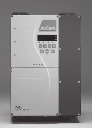
1 USER MANUAL
2 CONTENTS Contents Section 1 Caution Statements... 3 Section 2 Introduction Feature List... 4 Section 3 Basic Setup Procedure... 5 Section 4 Installation General Layout Power Termination Configuration Mounting Instructions Ventilation... 8 Section 5 Power Circuits Overview In-Line Connection In-Line Connection (Bypassed) Inside Delta Connection Inside Delta Connection (Bypassed) Power Factor Correction Main Contactor Section 6 Control Circuits Electrical Schematic Control Voltage Control Wiring Section 7 Serial Communication RS485 Serial Communication AP ASCII Protocol Modbus Protocols Section 8 Programmable Parameters Programming Procedure Function List Function Descriptions Section 9 Operation Local Control Panel Remote Control Restart Delay Pre-Start Tests Secondary Motor Settings Auto-Stop Short-Cut Section 10 Troubleshooting Trip Codes Trip Log General Faults Tests and Measurements Section 11 Application Examples Installation with Main Contactor Installation with Bypass Contactor K IMS2 Page 1
3 CONTENTS 11.3 Emergency Mode Operation Auxiliary Trip Circuit Soft Braking Two-Speed Motor Typical Start Current Requirements Section 12 Specifications Model Codes Current Ratings Dimensions and Weights Fuses Power Terminations General Technical Data Section 13 Authorised Representatives Page 2 IMS K
4 CAUTION STATEMENTS Section 1 Caution Statements This symbol is used throughout this manual to draw attention to topics of special importance to the installation and operation of IMS2 Series soft starters. Caution Statements cannot cover every potential cause of equipment damage but can highlight common causes of damage. It is the installer's responsibility to read and understand all instructions in this manual prior to installing, operating or maintaining the starter, to follow good electrical practice including applying appropriate personal protective equipment and to seek advice before operating this equipment in a manner other than as described in this manual. Isolate the soft starter completely from the power supply before attempting any maintenance work. Metal swarf in the cabinet can cause equipment failure. Do not apply voltage to the control input terminals. These are active 24 VDC inputs and must be controlled with potential free contacts. Contacts or switches operating the control inputs must be suitable for low voltage, low current switching (ie gold flash or similar). Cables to the control inputs must be segregated from mains voltage and motor cabling. Some electronic contactor coils are not suitable for direct switching with PCB mount relays. Consult the contactor manufacturer/ supplier to confirm suitability. Do not connect power factor correction capacitors to the output of IMS2 soft starters. If static power factor correction is employed, it must be connected to the supply side of the soft starter. Before installing the IMS2 without a main contactor, ensure this meets local regulations. If installing the IMS2 in a non-ventilated enclosure, a bypass contactor must be used to prevent excessive heat build-up. If installing a bypass contactor, ensure phase connections are correctly made (ie L1B-T1, L2B-T2, L3B-T3). Removing control voltage resets the thermal model. The examples and diagrams in this manual are included solely for illustrative purposes. The information contained in this manual is subject to change at any time and without prior notice. In no event will responsibility or liability be accepted for direct, indirect or consequential damages resulting from the use or application of this equipment. WARNING - ELECTRICAL SHOCK HAZARD IMS2 soft starters contain dangerous voltages when connected to mains voltage. Only a competent electrician should carry out the electrical installation. Improper installation of the motor or the soft starter may cause equipment failure, serious injury or death. Follow this manual and local electrical safety codes. GROUNDING AND BRANCH CIRCUIT PROTECTION It is the responsibility of the user or person installing the soft starter to provide proper grounding and branch circuit protection according to local electrical safety codes AuCom Electronics Ltd. All Rights Reserved. As AuCom is continuously improving its products it reserves the right to modify or change the specification of its products at any time without notice. The text, diagrams, images and any other literary or artistic works appearing in this document are protected by copyright. Users may copy some of the material for their personal reference but may not copy or use material for any other purpose without the prior consent of AuCom Electronics Ltd. AuCom endeavours to ensure that the information contained in this doument including images is correct but does not accept any liability for error, omission or differences with the finished product K IMS2 Page 3
5 INTRODUCTION Section 2 Introduction The IMS2 is a microcontroller based soft starter incorporating the latest technologies. It has been designed to provide a complete range of the most advanced soft start, soft stop and motor protection features. 2.1 Feature List Starting Constant current Current ramp Torque control Kickstart Stopping Soft stop Pump stop Soft braking Protection Motor overload (thermal model) Motor thermistor input Phase imbalance Phase rotation Electronic shearpin Undercurrent Auxiliary trip input Starter heatsink overtemperature Excess start time Supply frequency Shorted SCR Power circuit Motor connection Serial interface failure Interface Remote control inputs (3 x fixed, 1 x programmable) Relay outputs (1 fixed, 3 x programmable) 4-20 ma output (1 x programmable) RS485 serial link Human interface Local pushbuttons (Start, Stop, Reset, Local/Remote) Local programming pushbuttons (Function, Up, Down, Store) LED parameter display Starter status LEDs Power connection In-line or inside delta Bypass connections to retain motor protection even when bypassed 18 A to 1574 A (in-line) 27 A to 2361 A (inside delta) 200 VAC to 525 VAC (V5 models) 200 VAC to 690 VAC (V7 models) Sundry features IP42 or IP54 ( 253 A) IP00 ( 302 A) Current read-out Motor temperature read-out Trip log (eight position) Multiple function sets Restart delay High and low current flags Motor temperature flag Auto-reset Auto-stop Start counter Function lock/password protection Store/Restore function settings Emergency mode operation Thermal model override Page 4 IMS K
6 BASIC SETUP PROCEDURE Section 3 Basic Setup Procedure For simple applications, IMS2 soft starters can be installed using the three simple steps outlined below. For applications with advanced control, protection or interface requirements, a comprehensive review of this User Manual is recommended. 1. Installation and connection WARNING IMS2 soft starters contain dangerous voltages when connected to mains voltage. Only a competent electrician should carry out the electrical installation. Improper installation of the motor or the soft starter may cause equipment failure, serious injury or death. Follow this manual and local electrical safety codes. 1 Ensure the correct IMS2 model has been selected for the connected motor and application type. 2 Mount the IMS2, making sure to allow adequate clearance top and bottom for free circulation of air through the starter. (Refer to Mounting Instructions for details.) 3 Connect mains voltage to starter input terminals L1, L2, L3. 4 Connect the motor cables to starter output terminals T1, T2, T3. 5 Connect control voltage to starter input terminals A1-A2 or A2-A3. (Refer to Control Supply for details.) 1 Mains voltage 2 Semiconductor fuses (optional) 3 Control voltage 2. Programming For basic applications, the IMS2 only needs to be programmed with the nameplate full load current (FLC) of the motor: 1 Select Function 1 Motor Full Load Current by holding down the <FUNCTION> pushbutton and pressing the <UP> pushbutton repeatedly until the display shows "1". 2 Release the <FUNCTION> pushbutton. The display will show the currently stored value of Function 1 Motor Full Load Current. 3 Use the <UP> and <DOWN> pushbuttons to adjust the FLC setting to match the FLC of the motor. 4 Press the <STORE> pushbutton to store the new FLC setting. 5 Exit Programming Mode by holding down the <FUNCTION> pushbutton, pressing the <DOWN> pushbutton until the display shows "0", then releasing the <FUNCTION> pushbutton. 3. Operation The IMS2 is now ready to control the motor. Motor operation can be controlled using the <START> and <STOP> pushbuttons on the IMS2 local control panel. Two other functions that may be useful for basic installations are Function 2 Current Limit and Function 5 Stop Ramp Time. These functions can be adjusted as described above. (For a more detailed description of the programming procedure, refer to Programming Procedure.) K IMS2 Page 5


7 INSTALLATION Section 4 Installation 4.1 General Layout IMS20018 ~ IMS20125 IMS20141 ~ IMS20253 IMS20302 ~ IMS Control voltage terminals 2 Power terminals 3 Control terminals 4.2 Power Termination Configuration The bus bars on models IMS20302 ~ IMS21574 can be adjusted to provide four different input/output power terminal configurations. Input/Output Output Input Input/Output Input Output To adjust the bus bar configuration: 1. Remove the IMS2 covers and main control module. 2. Loosen and remove the bus bar fixing bolts. 3. Remove the bus bars and replace in the desired configuration. When re-orienting bus bars L1, L2, L3, the current transformers must also be relocated. 4. Refit and tighten the fixing bolts. The torque requirements are: IMS20302~IMS20897: 12 Nm IMS21153~IMS21574: 20 Nm Ensure that foreign matter does not contaminate the jointing compound and become trapped between the bus bar and its mounting plate. If the paste does become contaminated, clean and replace with a jointing compound suitable for aluminium to aluminium, or aluminium to copper joints. Page 6 IMS K
8 INSTALLATION 4.3 Mounting Instructions Models IMS20018 ~ IMS20253 can be wall mounted or installed inside another enclosure. These models can be mounted side by side with no clearance but a 100 mm allowance must be made top and bottom for air intake and exhaust. Models IMS20302 ~ IMS21574 have an IP00 rating and must be mounted in another enclosure. These models can be mounted side by side with no clearance but a 200 mm allowance must be made top and bottom for air intake and exhaust K IMS2 Page 7
9 INSTALLATION 4.4 Ventilation When installing IMS2 starters in an enclosure there must be sufficient airflow through the enclosure to limit heat rise. Temperature within the enclosure must be kept at, or below, the IMS2 maximum ambient temperature rating. If installing an IMS2 within a totally sealed enclosure, a bypass contactor is necessary to eliminate heat dissipation from the soft starter during run. Soft starters dissipate approximately 4.5 watts per motor ampere. The table below shows airflow requirements for selected motor currents. If other heat sources are installed in an enclosure along with the IMS2, an additional airflow allowance must be made for these items. Heat generation from semiconductor fuses can be avoided by installing these within the bypass loop. Motor Current (A) Heat (W) Required Airflow m 3 /minute m 3 /hour 5 o C Rise 10 o C Rise 5 o C Rise 10 o C Rise Page 8 IMS K
10 POWER CIRCUITS Section 5 Power Circuits 5.1 Overview IMS2 soft starters can be wired with a number of different power circuits depending on application requirements. 5.2 In-Line Connection The standard connection format is in-line (also known as three-wire). Mains voltage is connected to the starter input terminals L1, L2, L3. The motor cables are connected to the soft starter output terminals T1, T2, T3. KM1 F1 L1 T1 L1B L2 L2B L3 L3B T2 T3 E M KM1 F1 Main contactor (optional) Fuses (optional) 5.3 In-Line Connection (Bypassed) IMS2 soft starters can be bypassed while the motor is running. Special terminals (L1B, L2B, L3B) are provided for connecting the bypass contactor. These terminals allow the IMS2 to provide all protection and current monitoring functions even when bypassed. The Run Output (terminals 23, 24) should be used to control operation of the bypass contactor. The bypass contactor can be AC1 rated for the motor full load current. KM2 KM1 L1 T1 F1 L1B L2 L2B L3 L3B T2 T3 E M KM2 KM1 KM2 F1 Main contactor (optional) Bypass contactor Fuses (optional) K IMS2 Page 9
11 POWER CIRCUITS 5.4 Inside Delta Connection IMS2 soft starters support inside delta (six-wire) connection. When connected in inside delta configuration, the soft starter carries only phase current. This means the IMS2 can be used with motors which have a full load current rating up to 50% greater than the soft starter s standard current rating. KM1 F1 L1 T1 L1B U1 U2 L2 L2B T2 V1 W1 M V2 W2 L3 T3 L3B E KM1 F1 Main contactor Fuses (optional) A motor usually has two rows of three terminals in the motor termination box. If the motor windings are connected in delta, there will be three links fitted. Each link is connected from a terminal in the top row to one in the bottom row. If the motor windings are connected in star, there will be one link fitted. This link is connected to all three terminals in one row. For inside delta connection, remove all links from the motor termination box. Connect the three output terminals of the soft starter (T1, T2, T3) to one end of each motor winding. Connect the opposite end of each motor winding to a different phase on the starter's input. For example: Remove the links from the motor termination box. Connect the incoming phases to L1, L2, L3 on the IMS2. Connect each output phase from the IMS2 to one end of an individual motor winding: T1-U1, T2-V1, T3-W1. Connect the other end of each individual motor winding to a different phase on the soft starter's input: U2-L2, V2-L3, W2-L1. CAUTION When connecting the IMS2 in inside delta configuration, always install a main contactor or shunt trip circuit breaker. Page 10 IMS K
12 POWER CIRCUITS 5.5 Inside Delta Connection (Bypassed) IMS2 starters support inside delta connection with bypass. KM2 KM1 T1 F1 T2 T3 U1 U2 V1 M V2 W1 W KM2 KM1 KM2 F1 Main contactor Bypass contactor Fuses (optional) 5.6 Power Factor Correction If power factor correction is used, a dedicated contactor should be used to switch in the capacitors. Power factor correction capacitors must be connected to the input side of the soft starter. Connecting power factor correction capacitors to the output side will damage the soft starter. 5.7 Main Contactor The IMS2 is designed to operate with or without a main contactor. In many regions, statute requires a main contactor to be used with electronic motor control equipment. This is not necessary for starter operation, but provides safety benefits. Using a main contactor also isolates the soft starter SCRs in the off state, when they are most susceptible to damage from voltage transients. A main contactor should always be used when the IMS2 is installed in inside delta configuration. The IMS2 can directly control a main contactor by assigning one of the relay outputs to Main Contactor control. As an alternative to a main contactor, either a circuit breaker with a no volt release coil operated by the soft starter's trip output, or a motor operated circuit breaker can be considered. If a motor operated circuit breaker is used as a main contactor, the potential delay between the breaker being told to close and phase power being applied to the IMS2 could cause the IMS2 to trip on Power Circuit fault. To avoid this, close the motorised breaker directly and use the breaker s auxiliary contacts (or a slave relay with gold flash contacts) to control the soft starter. Select a main contactor with AC3 rating is equal to or greater than the full load current rating of the connected motor K IMS2 Page 11
13 CONTROL CIRCUITS Section 6 Control Circuits 6.1 Electrical Schematic 1 Control voltage 4 RS485 serial interface 2 Remote control inputs 5 Relay outputs C23-C24 Start Programmable output A C31-C32 Stop Run output C41-C42 Reset Programmable output B C53-C54 Programmable input A 41, 42, 44 Programmable output C 3 Thermistor input 6 Analog output 6.2 Control Voltage Voltage must be connected to the soft starter's control voltage terminals. The correct control voltage depends on the soft starter model. IMS2xxxx-xx-C12-xx-xx models: 110 VAC (A1-A2) or 230 VAC (A2-A3) IMS2xxxx-xx-C24-xx-xx models: 230 VAC (A2-A3) or 400 VAC (A1-A2) IMS2xxxx-xx-C45-xx-xx models: 460 VAC (A1-A2) or 575 VAC (A2-A3) IMS2 Model Maximum VA IMS20018 ~ IMS VA IMS20067 ~ IMS VA IMS20141 ~ IMS VA IMS20253 ~ IMS VA IMS21153 ~ IMS VA 6.3 Control Wiring IMS2 operation can be controlled using the local control pushbuttons, remote control inputs or the serial communications link. The <LOCAL/REMOTE> pushbutton can be used to switch between local and remote control. Refer to Function 20 Local/Remote Operation for details. Page 12 IMS K
14 CONTROL CIRCUITS Remote Control Inputs The IMS2 has four remote control inputs. Contacts used for controlling these inputs should be low voltage, low current rated (gold flash or similar). Remote pushbutton control Relay Outputs C23 C24 C31 C32 C41 C42 C53 C54 Two-wire control C23 C24 C31 C32 C41 C42 C53 C C 1 Start 2 Stop 3 Reset 4 Input A CAUTION Do not apply voltage to the control input terminals. These are active 24 VDC inputs and must be controlled with potential free contacts. Contacts or switches operating the control inputs must be suitable for low voltage, low current switching (ie gold flash or similar). Cables to the control inputs must be segregated from mains voltage and motor cabling. The IMS2 provides four relay outputs, one fixed and three programmable. The Run output closes when the soft start is complete (when the starting current falls below 120% of the programmed motor full load current) and remains closed until the beginning of a stop (either soft stop or coast to stop). Operation of the programmable outputs is determined by the settings of Functions 21, 22 and 23. If assigned to Main Contactor, the output activates as soon as the soft starter receives a start command and remains active while the soft starter is controlling the motor (until the motor starts a coast to stop, or until the end of a soft stop). If assigned to Start/Run, the output activates when the soft starter completes its pre-start tests and remains active while the soft starter is controlling the motor (until the motor starts a coast to stop, or until the end of a soft stop). If assigned to a trip function, the output activates when the specified trip occurs. If assigned to a flag, the output activates when the specified flag is active (refer to Functions 40, 41 and 42). Motor Thermistors CAUTION Some electronic contactor coils are not suitable for direct switching with PCB mount relays. Consult the contactor manufacturer/ supplier to confirm suitability. Motor thermistors (if installed in the motor) may be connected directly to the IMS2. The soft starter will trip when the resistance of the thermistor circuit exceeds approximately 2.8 kω. The IMS2 can be reset once the thermistor circuit resistance falls below approximately 2.8 kω. No motor thermistors Motor thermistors B4 B5 B4 B B Thermistor input NOTE If the thermistor circuit is open, the IMS2 will not run. The thermistor circuit should be run in screened cable and must be electrically isolated from earth and all other power and control circuits. If no motor thermistors are connected to the IMS2 there must be a link across the thermistor input terminals B4-B5 or Function 34 Motor Thermistor must be set to 1 (Off) K IMS2 Page 13
15 SERIAL COMMUNICATION Section 7 Serial Communication 7.1 RS485 Serial Communication The IMS2 has a non-isolated RS485 serial communication link. RS485 - B1 GND B2 + B3 The serial link can be used to: control IMS2 operation query IMS2 status and operating data read (download) function values from the IMS2 write (upload) function values to the IMS2 Three serial protocols are available: AP ASCII, Modbus RTU and Modbus ASCII. Select the relevant protocol using Function 63 Serial Protocol. NOTE Power cabling should be kept at least 300 mm away from communications cabling. Where this separation is not possible, magnetic shielding should be provided to reduce induced common mode voltages. The IMS2 can be programmed to trip if the RS485 serial link fails. This is done by setting Function 60 Serial Timeout. Baud rate is set by Function 61 Serial Baud Rate. The starter address is assigned using Function 62 Serial Satellite Address. 7.2 AP ASCII Protocol NOTE Slave addresses must be two digits. Addresses less than 10 must have a leading zero (0). The IMS2 may take up to 250 ms to respond. The host software timeout should be set accordingly. The satellite address and baud rate may also be altered through the serial interface. The new settings will take effect after the current serial programming session is terminated by the master. The serial master application must ensure that altering these function values does not cause communication problems. The message fragments used in communicating with the IMS2 are shown below. The message fragments may be assembled into complete messages as described in the sections that follow. NOTE Data must be transmitted in 8-bit ASCII, no parity, one stop bit. Message Fragment Type Send address Send command Send request Receive data Receive status ACK (acknowledge) NAK (negative acknowledge) ERR (error) ASCII Character String or (Hexadecimal Character String) EOT [nn] (04h [nn] STX [ccc] (02h [ccc] STX [dddd] (02h [dddd] STX [ssss] (02h [ssss] ACK or (06h) NAK or (15h) BEL or (07h) [lrc] [lrc] [lrc] [lrc] [lrc] [lrc] [lrc] [lrc] ENQ or 05h) ETX or 03h) ETX or 03h) Page 14 IMS K
16 SERIAL COMMUNICATION nn = two byte ASCII number representing the soft starter address where each decimal digit is represented by n. lrc = two byte longitudinal redundancy check in hexadecimal. ccc = three byte ASCII command number where each character is represented by c. dddd = four byte ASCII number representing the current or temperature data where each decimal digit is represented by d. ssss = four byte ASCII number. The first two bytes are ASCII zero. The last two bytes represent the nibbles of a single byte of status data in hexadecimal. Commands Commands can be sent to the soft starter using the following format: Send address ACK Send command ACK Possible error responses: NAK (Invalid LRC) = Master = Slave (soft starter) Command ASCII Comment Start B10 Initiates a start Stop B12 Initiates a stop Reset B14 Resets a trip state Quick stop B16 Initiates an immediate removal of voltage from the motor. Any soft stop settings are ignored. Forced communication trip B18 Causes a communications trip Status Retrieval Starter status can be retrieved from the soft starter using the following format: Send address ACK Send request Receive status Possible error responses: NAK (Invalid LRC) = Master = Slave (soft starter) Request ASCII Receive Status (ssss) Version C16 Serial protocol version number. Trip Code C18 Requests the trip status of the IMS = No trip 0 = Shorted SCR 1 = Excess start time 2 = Motor overload (thermal model) 3 = Motor thermistor 4 = Phase imbalance 5 = Supply frequency 6 = Phase sequence 7 = Electronic shearpin 8 = Power circuit fault 9 = Undercurrent 10 = Heatsink overtemperature (F) 11 = Invalid motor connection (P) 12 = Auxiliary input (J) 13 = Out of range FLC (L) 14 = Incorrect main control module (Y) 15 = RS485 communication fault (C) 16 = Forced communication trip (H) 17 = CPU error (U) Product Version C20 Bit No. Description 0-2 Function list version 3-7 Starter type (2 = IMS2) K IMS2 Page 15
17 SERIAL COMMUNICATION Starter Status C22 Bit No. Description = Not used 1 = Waiting 2 = Starting (incl. Pre-start tests) 3 = Running 4 = Stopping 5 = Restart Delay 6 = Tripped 7 = Programming Mode 4 1 = Positive phase sequence detected 5 1 = Current exceeds the FLC 6 0 = Uninitialised 1 = Initialised nb: bit 4 is not valid unless bit 6 = = Communication connection status OK 1 = Communication connection fault Data Retrieval Data can be retrieved from the soft starter using the following format: Send address ACK Send request Receive data Possible error responses: NAK (Invalid LRC) = Master = Slave (soft starter) Request ASCII Receive Data (dddd) Motor current D10 Requests motor current. The data is four byte decimal ASCII. Minimum value 0000 A, maximum value 9999 A. Motor temperature D12 Read Function Values from the IMS2 Requests the calculated value of the motor thermal model as a % of motor thermal capacity. The data is four byte decimal ASCII. Minimum value is 0000%. Trip point is 0105%. Function values may be read (downloaded) from the soft starter at any time using the following format: Send address ACK Read function ACK Repeat until master sends NAK Function number Function value Possible error messages 1 1, 2 1:NAK = Invalid LRC 2: ERR = Invalid function number = Master = Slave (soft starter) NAK Read Function ASCII Comment Download Functions P10 Readies the IMS2 to download function values. Page 16 IMS K
18 SERIAL COMMUNICATION Write Function Values to the IMS2 Function values may be written (uploaded) to the soft starter only when it is in the off state, ie not starting, running, stopping or tripped. Use the following format to write function values: Send address Enter Serial Programming Mode ACK Write function ACK Function number Exit Serial Programming Mode and store parameters to EEPROM Repeat until master sends NAK ACK Function value Function value Possible error responses: 1, 2 1, 3 1, 4 1: NAK = Invalid LRC 2: ERR = Unable to program (motor running) 3: ERR = Invalid function number 4: ERR = Function value out of range = Master = Slave (soft starter) Write Function ASCII Comment Upload Functions P12 Readies the IMS2 to upload function values. When the IMS2 receives a Write Function command it enters Serial Programming Mode. In Serial Programming Mode, the local control pushbuttons and remote inputs are inoperative, the serial start command is unavailable and the soft starter's display flashes the letters SP. When the Write Function command is terminated by the master or with an error or timeout, the functions are written to the EEPROM and the IMS2 exits Serial Programming Mode. NOTE Serial Programming Mode will time out in 500 ms if there has been no serial activity. The following functions may not be adjusted: Function 100, 101, 102, 103, 110, 111, 112, 113 and 117. If values for these functions are uploaded to the IMS2 there will be no effect and an error will be generated. NAK K IMS2 Page 17
19 SERIAL COMMUNICATION Calculating the Checksum (LRC) Each command string sent to and from the starter includes a checksum. The form used is the longitudinal redundancy check (LRC) in ASCII hex. This is an 8-bit binary number represented and transmitted as two ASCII hexadecimal characters. To calculate LRC: 1. Sum all ASCII bytes 2. Mod 's complement 4. ASCII convert For example Command String (Start): ASCII STX B 1 0 or 02h 42h 31h 30h ASCII Hex Binary STX 02h B 42h h h A5h SUM (1) A5h MOD 256 (2) 5Ah 's COMPLEMENT 01h = 5Bh 's COMPLEMENT (3) ASCII 5 B ASCII CONVERT (4) or 35h 42h LRC CHECKSUM The complete command string becomes: ASCII STX B B ETX or 02h 42h 31h 30h 35h 42h 03h To verify a received message containing an LRC: 1. Convert last two bytes of message from ASCII to binary 2. Left shift 2 nd to last byte four bits 3. Add to last byte to get binary LRC 4. Remove last two bytes from message 5. Add remaining bytes of message 6. Add binary LRC 7. Round to one byte 8. The result should be zero Response or status bytes are sent from the starter as an ASCII string: STX [d1]h [d2]h [d3]h [d4]h LRC1 LRC2 ETX d1 = 30h d2 = 30h d3 = 30h plus upper nibble of status byte right shifted by four binary places d4 = 30h plus lower nibble of status byte For example status byte = 1Fh, response is: STX 30h 30h 31h 46h LRC1 LRC2 ETX 7.3 Modbus Protocols The soft starter can communicate using either Modbus RTU or Modbus ASCII. Use Function 63 Serial Protocol to select the protocol and Function 64 Modbus Parity to select the parity. All the functionality of the IMS2 serial protocol is implemented in the Modbus RTU and ASCII protocols using the Modbus register structure as follows. Page 18 IMS K
20 SERIAL COMMUNICATION NOTE Command, Starter Status, Trip Code, Current, Temperature, Product type/version, RS485 Protocol version, and Function Upload (write) must be sent individually, ie one data word request at a time (single read/write). The Modbus ASCII protocol is restricted to transferring one function download at a time (single read). The Modbus RTU protocol is restricted to transferring a maximum of six function downloads at a time (multiple read). Refer to the Modbus standard at for protocol details. Register Register Type Description Address Command Single write 1 = Start 2 = Stop 3 = Reset 4 = Quick Stop 5 = Forced Communication Trip Starter Status Single read Bit No. Description = Not used 1 = Waiting 2 = Starting (incl. Pre-start tests) 3 = Running 4 = Stopping 5 = Restart delay 6 = Tripped 7 = Programming Mode 4 1 = Positive phase sequence detected 5 1 = Current exceeds the FLC 6 0 = Uninitialised 1 = Initialised nb: bit 4 is not valid unless bit 6 = = Communication connection status OK 1 = Communication connection fault Trip Code Single read 255 = No trip 0 = Shorted SCR 1 = Excess start time 2 = Motor thermal model 3 = Motor thermistor 4 = Phase imbalance 5 = Supply frequency 6 = Phase sequence 7 = Electronic shearpin 8 = Power circuit fault 9 = Undercurrent 10 = Heatsink overtemperature (F) 11 = Invalid motor connection (P) 12 = Auxiliary Input (J) 13 = Out of range FLC (L) 14 = Incorrect control module (Y) 15 = RS485 communication fault (C) 16 = Forced communication trip (H) 17 = CPU error (U) Current Single read Temperature Single read Product type Single read Bit No. Description and version 0-2 Function list version 3-7 IMS2 = RS485 protocol Single read RS485 serial protocol version version to Function 1 to Function 117 Multiple read / Single write Refer to Function Descriptions for detail K IMS2 Page 19
21 SERIAL COMMUNICATION Modbus HEX Functions Two Modbus HEX functions are supported: 03 Single / Multiple Read 06 Single Write The IMS2 does not accept broadcast functions. Examples of Modbus protocol NOTE Least significant bit is transmitted first. Command: Start Slave Address Function Code Register Address Data Checksum (LRC or CRC) Starter status: Starter running Slave Address Function Code Register Address Data Checksum xxxx0011 (LRC or CRC) Trip code: Overcurrent trip Slave Address Function Code Register Address Data Checksum (LRC or CRC) Read function from the soft starter: Read from Function 3 Initial Start Current, 350% Slave Address Function Code Register Address Data Checksum (LRC or CRC) Write function to the soft starter: Write to Function 12 Soft Stop Mode, set = 1 (Pump Control) Note: Returns error if out of range Slave Address Function Code Register Address Data Checksum (LRC or CRC) Page 20 IMS K

22 PROGRAMMABLE PARAMETERS Section 8 Programmable Parameters 8.1 Programming Procedure Step 1. Enter Programming Mode and select the function to be viewed or adjusted. 1 Press and hold the <FUNCTION> pushbutton. 2 Use the <UP> and <DOWN> pushbuttons to select the required function number. Function numbers are left justified and flash. 3 When the required function number is displayed, release the <FUNCTION> pushbutton. The display will show the currently stored setting. Settings are right justified and do not flash. Step 2. Alter the function setting. 1 Use the <UP> and <DOWN> pushbuttons to adjust the setting. To cancel changes, press the <FUNCTION> pushbutton. Step 3. Store the new setting. 1 Press the <STORE> pushbutton to store the displayed setting. 2 To check that the new value has been correctly stored, press then release the <FUNCTION> pushbutton. The display will show the new setting. Step 4. Exit Programming Mode. 1 Once all changes have been made, exit Programming Mode by using the <FUNCTION> and <DOWN> pushbuttons to select Function 0 (Run Mode) K IMS2 Page 21
23 PROGRAMMABLE PARAMETERS 8.2 Function List Factory default User set 1 User set 2 Factory default User set 1 No. Function No. Function Primary Motor Settings Secondary Motor Settings 1 Motor Full Load Current - 80 Motor Full Load Current - 2 Current Limit Current Limit Initial Start Current Initial Start Current Start Ramp Time 1 83 Start Ramp Time 1 5 Stop Ramp Time 0 84 Stop Ramp Time 0 6 Motor Start Time Constant Motor Start Time Constant 10 7 Phase Imbalance Sensitivity 5 86 Phase Imbalance Sensitivity 5 8 Undercurrent Protection Undercurrent Protection 20 9 Electronic Shearpin Protection Electronic Shearpin Protection 400 Start/Stop Formats Protection Delays 10 Torque Control 0 90 Phase Imbalance Trip Delay 3 11 Kickstart 0 91 Undercurrent Trip Delay 5 12 Soft Stop Mode 0 92 Electronic Shearpin Delay 0 13 Auto-Stop Run Time 0 93 Out Of Frequency Trip Delay 0 Starter Functionality 94 Auxiliary Trip Delay 0 20 Local/Remote Operation 0 Read Only Data 21 Relay Output A Functionality Model Number - 22 Relay Output B Functionality Start Counter (1000's) - 23 Relay Output C Functionality Start Counter (1's) - 24 Input A Functionality Trip Log - Protection Settings Restricted Functions 30 Excess Start Time Access Code 0 31 Phase Sequence Update Access Code 0 32 Restart Delay Function Lock 0 33 Phase Imbalance Restore Function Settings 0 34 Motor Thermistor Emergency Mode Format 0 35 Heatsink Overtemperature Emergency Mode Trip Relay 0 36 Auxiliary Trip Mode Thermal Model Override - Set Points 117 Thermal Model Override Count - 40 Low Current Flag High Current Flag Motor Temperature Flag Field Calibration 100 Analogue Output ma Output Functionality 0 Application Detail ma Output Range Max 100 IMS2 model ma Output Range Min 0 IMS2 serial number Serial Communications IMS2 connection format In-line 60 Serial Timeout 0 Inside delta 61 Serial Baud Rate 4 Bypassed 62 Serial Satellite Address 20 Motor current A 63 Serial Protocol 1 Motor kw kw 64 Modbus Parity 0 Driven machine Auto-Reset Start current (%FLC) % FLC 70 Auto-Reset Configuration 0 Start time (seconds) s 71 Auto-Reset Number of Resets 1 Starts per hour 72 Auto-Reset Group A & B Delay 5 Ambient temperature ( C) ºC 73 Auto-Reset Group C Delay 5 Application Reference If you require assistance during commissioning or troubleshooting, please fill in this table and give the information to your supplier. User set 2 Page 22 IMS K
24 PROGRAMMABLE PARAMETERS 8.3 Function Descriptions Primary Motor Settings 1 Motor Full Load Current Range: Model dependent Sets the IMS2 for the connected motor s full load current. Set to the full load current rating (in amperes) shown on the motor nameplate. 2 Current Limit Range: % FLC Default: 350% Sets the current limit for constant current soft starting. Constant current is the traditional form of soft starting, which raises the current from zero to a specified level and keeps the current stable at that level until the motor has accelerated. Current (%motor full load current) 700% 600% 500% 400% 300% 200% 100% : Initial current (Function 3) 2: Current limit (Function 2) 3: Full voltage current 10% 20% 30% 40% 50% 60% 70% 80% 90% 100% Rotor speed (% full speed) Constant current starting is ideal for applications where the start current must be kept below a particular level. Set the current limit so that: The motor is supplied with sufficient start current to enable it to produce enough torque to easily accelerate the connected load. Desired starting performance is obtained. IMS2 ratings are not exceeded. 3 Initial Start Current Range: % FLC Default: 350% Sets the initial start current level for current ramp start mode. Function 3 Initial Start Current and Function 4 Start Ramp Time are used together to activate and control the current ramp start mode. Current ramp soft starting raises the current from a specified starting level (1) to a maximum limit (3), over an extended period of time (2). Current (%motor full load current) 700% 600% 500% 400% 300% 200% 100% % 20% 30% 40% 50% 60% 70% 80% 90% 100% 3 1: Initial current (Function 3) 2: Start ramp time (Function 4) 3: Current limit (Function 2) 4: Full voltage current Rotor speed (% full speed) Current ramp starting can be useful for applications where: K IMS2 Page 23
25 PROGRAMMABLE PARAMETERS the load can vary between starts (for example a conveyor which may start loaded or unloaded). Set the initial current (Function 3) to a level that will start the motor with a light load, and the current limit (Function 2) to a level that will start the motor with a heavy load. the load breaks away easily, but starting time needs to be extended (for example a centrifugal pump where pipeline pressure needs to build up slowly). the electricity supply is limited (for example a generator set), and a slower application of load will allow greater time for the supply to respond. 4 Start Ramp Time Range: 1 30 seconds Default: 1 second Sets the ramp time for current ramp start mode. Set the start ramp time to optimise start performance. 5 Stop Ramp Time Range: seconds Default: 0 seconds Sets the soft stop ramp time for soft stopping the motor. The soft stop mode is selected using Function 12. Setting Function 5 to 0 disables soft stop. If using soft stop and a main contactor, the contactor must remain closed until the end of the stop ramp time. The IMS2 programmable outputs A, B or C can be set to control the main contactor. Refer to Functions 21, 22, 23 for programmable output assignment details. 6 Motor Start Time Constant Range: seconds Default: 10 seconds Sets the motor thermal capacity used by the IMS2's motor thermal model. NOTE A setting of 0 seconds disables the soft starter's motor thermal model. Use this setting only if another form of motor protection is used. A motor s thermal capacity (also known as maximum locked rotor time or maximum DOL start time) is the maximum time a motor can maintain locked rotor current from cold. This information is available from the motor datasheet or the motor supplier. The IMS2's motor thermal model assumes a locked rotor current of 600%. If the connected motor s locked rotor current differs from this, greater accuracy can be achieved by using a normalised MSTC figure: MSTC = B %LRC x maximum start time NOTE Setting Function 6 Motor Start Time Constant according to the motor s actual thermal capacity allows safe use of the motor s full overload capability both to start the load and ride through overload conditions. Cold start curves Current (% full load current) B MSTC = 30 seconds MSTC = 20 seconds MSTC = 10 seconds MSTC = 5 seconds A more conservative approach can be taken by setting a reduced MSTC for easy to start loads that will not experience transient operating overloads as a part of normal operation. Using a reduced Page 24 IMS K
26 PROGRAMMABLE PARAMETERS 7 Phase Imbalance Sensitivity MSTC figure has the advantage of maximising motor life. The life of a motor is strongly influenced by its maximum winding temperature, and the expected life span of a motor is roughly halved for every ten degree rise in temperature. The temperature rise depends on the motor losses and the motor cooling. The highest stress on the motor is during start, and can be minimised by restricting the duration and frequency of starts. A reduced MSTC setting will also cause the soft starter's protection functions to operate before the motor is thermally stressed. A suitable reduced MSTC figure can be established by observing the modelled motor temperature as shown on the IMS2's display, and adjusting the MSTC parameter such that after a normal start which has been preceded by a period of running at maximum load, the calculated motor temperature is approaching 90%. Range: = Highest sensitivity (lowest imbalance) I 5 = Normal sensitivity (default) I 10 = Lowest sensitivity (highest imbalance) Sets the sensitivity of the phase imbalance protection. 8 Undercurrent Protection Range: 0% 100% FLC Default: 20% Sets the trip point for undercurrent protection as a percentage of motor full load current. Set to a level below the motor s normal working range and above the motor s magnetising (no load) current (typically 25% - 35% of rated full load current). A setting of 0% disables the protection. NOTE Undercurrent protection only operates while the soft starter is running. 9 Electronic Shearpin Protection Range: 80% 550% FLC Default: 400 % Sets the trip point for electronic shearpin protection as a percentage of motor full load current. Start/Stop Formats 10 Torque Control NOTE Electronic shearpin protection only operates while the soft starter is running. The activation of this trip can be delayed by setting Function 92 Electronic Shearpin Delay. Options: 0 = Off (default) 1 = On Enables or disables the torque control function. Torque control provides a more linear acceleration than current limit or current ramp start modes alone. 11 Kickstart Options: 0 = Off (default) 1 = On Activates the kickstart function. Kickstart provides extra torque at the beginning of a start and can be useful for accelerating loads that require high breakaway torque but then accelerate easily. NOTE Kickstart subjects the mechanical equipment to increased torque levels. Ensure the motor, load and couplings can handle the additional torque before using this feature K IMS2 Page 25
27 PROGRAMMABLE PARAMETERS 12 Soft Stop Mode Options: 0 = Standard soft stop (default) 1 = Pump control Selects the active soft stop mode. The standard soft stop mode automatically monitors motor deceleration and will provide optimum control for most applications. Pump control may offer superior performance in some applications and can be of particular benefit in some pumping applications. To disable soft stop, set Function 5 Soft Stop Time to Auto-Stop Run Time Range: units Default: 0 units (off) 1 unit = 6 minutes Sets the run time for the auto-stop function. The soft starter will automatically stop after running for the specified period. The maximum run time is before auto-stop is 25 hours, 30 minutes (6 minutes x 255), measured from the last start signal. A value of 0 disables auto-stop. For a short-cut to this function, refer to Operation. Starter Functionality 20 Local/Remote Operation Options: 0 (IMS2 <LOCAL/REMOTE> pushbutton always enabled, default) 1 (IMS2 <LOCAL/REMOTE> pushbutton disabled while motor running) 2 (Local control only: IMS2 pushbuttons enabled, remote inputs disabled) 3 (Remote control only: IMS2 pushbuttons disabled, remote inputs enabled) Enables and disables the local pushbuttons and remote control inputs. Also determines when and if the <LOCAL/REMOTE> pushbutton can be used to switch between local and remote control. 21 Relay Output A Functionality Options: 0 = Tripped 1 = Overcurrent trip 2 = Undercurrent trip 3 = Motor thermistor trip 4 = Heatsink overtemperature trip 5 = Phase imbalance trip 6 = Electronic shearpin trip 7 = Low current flag 8 = High current flag 9 = Motor temperature flag 10 = Start/Run 11 = Main contactor (default) 12 = Auxiliary trip Selects the functionality of programmable Relay Output A. Start signal Current Output voltage Relay functions: 22 Relay Output B Functionality Main contactor Start/run Run Pre-start tests Range: 0 12 Default: 10 (Start/Run) Assigns the functionality of programmable Relay Output B. Refer to Function 21 Relay Output A Functionality for details. 23 Relay Output C Functionality Range: 0 12 Default: 0 (Tripped) Page 26 IMS K
28 PROGRAMMABLE PARAMETERS Assigns the functionality of programmable Relay Output C. Refer to Function 21 Relay Output A Functionality for details. 24 Input A Functionality Determines the functionality of programmable Input A. Options: 0 (Parameter set selection, default) The IMS2 can be programmed with two separate sets of motor and starting data. The primary parameter set is programmed using Functions 1 ~ 9. The secondary parameter set is programmed using Functions 80 ~ 88. To use the secondary parameter set, Function 24 Input A Functionality must be set to 0 and there must be a closed Protection Settings 30 Excess Start Time 1 (Auxiliary trip (normally open) 2 (Auxiliary trip (normally closed) circuit across Input A when a start is called for. The IMS2 can be tripped by a remote circuit connected to Input A when Function 24 Input A Functionality is set = 1 (Auxiliary trip - normally open). A closed circuit across Input A trips the IMS2. Functionality of the auxiliary trip feature can be adjusted using Function 94 Auxiliary Trip Delay and Function 36 Auxiliary Trip Mode. The IMS2 can be tripped by a remote circuit connected to Input A when Function 24 Input A Functionality is set = 2 (Auxiliary trip - normally closed). An open circuit across Input A trips the IMS2. Functionality of the auxiliary trip feature can be adjusted using Function 94 Auxiliary Trip Delay and Function 36 Auxiliary Trip Mode. 3 (Emergency run) In emergency run the soft starter continues to run until stopped, ignoring specified protection functions are ignored. Closing the circuit across Input A activates emergency run. The IMS2 will start the motor, if not already running, and continue operation ignoring the trip conditions specified in Function 114 Emergency Mode - Format. Opening the circuit across Input A ends emergency run and returns control to the normal control circuits. Functionality of the trip relay during emergency run operation is determined by Function 115 Emergency Mode - Trip Relay Operation. Range: seconds Default: 20 seconds Sets the maximum time allowed for the motor to start. If the motor does not reach full speed within the programmed limit, the starter will trip. Set for a period slightly longer than required for a normal healthy start. A setting of 0 disables this protection. NOTE Ensure the excess start time setting is within the soft starter's rated capability. This ensures the soft starter is also protected from overloads caused by stalled motors. 31 Phase Sequence Range: 0 = Off (forward and reverse rotation accepted, default) 1 = Forward rotation only (reverse rotation prohibited) 2 = Reverse rotation only (forward rotation prohibited) Selects the valid phase sequences for phase sequence protection. The IMS2 examines the sequence of the phases at its input terminals and trips if the actual sequence does not match the selected option. 32 Restart Delay Range: units Default: 1 (10 seconds) 1 unit = 10 seconds K IMS2 Page 27
29 PROGRAMMABLE PARAMETERS Sets the minimum time between the end of a stop and the beginning of the next start. During the restart delay, the AMPS or TEMP LED will flash, indicating the motor cannot yet be restarted. NOTE A setting of 0 selects the minimum restart delay period (1 second). 33 Phase Imbalance Options: 0 = On (default) 1 = Off Enables or disables the phase imbalance protection. 34 Motor Thermistor Options: 0 = On (default) 1 = Off Enables or disables the thermistor protection feature. 35 Heatsink Overtemperature Options: 0 = On (default) 1 = Off Enables or disables the IMS2's heatsink overtemperature protection. NOTE Defeating the protection may compromise starter life and should only be done in the case of emergency. 36 Auxiliary Trip Mode Options: 0 = Active at all times (default) 1 = Active during starting, run and stopping (disabled while stopped) 2 = Active during run only 3 = Active 30 seconds after the start command 4 = Active 60 seconds after the start command 5 = Active 90 seconds after the start command 6 = Active 120 seconds after the start command 7 = Active 180 seconds after the start command 8 = Active 240 seconds after the start command 9 = Active 300 seconds after the start command 10 = Active 600 seconds after the start command 11 = Active 900 seconds after the start command 12 = Active 1200 seconds after the start command Determines when the IMS2 monitors the auxiliary trip input. Refer to Function 24 Input A Functionality for further detail. Set Points 40 Low Current Flag Range: 1 100% FLC Default: 50% Sets the current level (% FLC) at which the low current flag operates. The low current flag can be assigned to programmable Relay Outputs A, B or C, to indicate that motor current has fallen below the programmed value. 41 High Current Flag Range: % FLC Default: 105% Sets the current level (% FLC) at which the high current flag operates. The high current flag can be assigned to programmable Relay Outputs A, B or C, to indicate that motor current has exceeded the programmed value. 42 Motor Temperature Flag Range: 0 105% Motor Temperature Default: 80% Page 28 IMS K
USERS IMS2 SERIES SOFT STARTERS
 USERS M A N U A L IMS2 SERIES SOFT STARTERS CONTENTS Basic Setup Procedure... 3 Section 1 Caution Statements... 4 Section 2 Section 3 Section 4 Section 5 Section 6 Section 7 Section 8 General 2.1 Overview...
CONTENTS. Basic Setup Procedure Section 1 Caution Statements Programming and Operation IMS2 SERIES H
 USER M A N U A L IMS2 SERIES SOFT STARTERS CONTENTS Basic Setup Procedure... 3 Section 1 Caution Statements... 4 Section 2 Section 3 Section 4 Section 5 Section 6 Section 7 Section 8 General 2.1 Overview...
CONTENTS IMS2 SERIES A. 2.1 Overview Feature List Part Number Format... 3
 CONTENTS Section 1 Section 2 Section 3 Section 4 Section 5 Section 6 Section 7 Caution Statements General Description 2.1 Overview... 3 2.2 Feature List... 3 2.3 Part Number Format... 3 Specifications
1. Introduction. 2. Installation MODBUS INTERFACE
 5551.C 8473.C MODBUS INTERFACE PIM-MB-1 Modbus Interface 1. Introduction AuCom soft starters can be controlled and monitored across an RS485 serial communication network using the Modbus RTU and AP ASCII
It is the installer's responsibility to follow all instructions in this manual and to follow correct electrical practice.
 MCD Modbus Module Instructions Important User Information INSTALLATION INSTRUCTIONS: MCD MODBUS MODULE Order Code: 175G9000 1. Important User Information Observe all necessary safety precautions when controlling
Section 0.0 Warnings... 2 Section 1.0 Quick Set-up... 3 Section 2.0 Description Section 3.0. Section 4.0. Section 5.0. Section 6.0. Section 7.
 Section 0.0 Warnings... 2 Section 1.0 Quick Set-up... 3 Section 2.0 Description... 4 Contents Section 3.0 Section 4.0 Section 5.0 Section 6.0 Section 7.0 Section 8.0 Installation 3.1 Mechanical Installation...
Section 0.0 Warnings... 3 Section 1.0 Quick Set-up... 4 Section 2.0 Description Section 3.0. Section 4.0. Section 5.0. Section 6.0. Section 7.
 Section 0.0 Warnings... 3 Section 1.0 Quick Set-up... 4 Section 2.0 Description... 5 Contents Section 3.0 Section 4.0 Section 5.0 Section 6.0 Section 7.0 Section 8.0 Installation 3.1 Mechanical Installation...
User Guide. Modbus Module. For Digistart soft starters. Part Number: Issue: 3.
 User Guide Modbus Module For Digistart soft starters Part Number: 477-9-3 Issue: 3 General Information The manufacturer accepts no liability for any consequences resulting from inappropriate, negligent
MODBUS RTU MODULE INSTRUCTIONS. for use with WSIQ2/WSE
 INSTRUCTIONS MODBUS RTU MODULE for use with WSIQ2/WSE WorldWide Electric Corporation Phone: 1-8-88-2131 Fax: 1-8-711-1616 www.worldwideelectric.net Product Compatibility This communications module is suitable
1. Warnings Introduction Mechanical Installation Electrical Installation Application Examples...
 MCD 500 Operating Instructions Contents Contents 1. Warnings... 3 2. Introduction... 4 2.1. Feature List... 4 2.2. Type Code... 5 3. Mechanical Installation... 6 3.1. Mechanical Installation... 6 3.2.
Instructions. Modbus RTU Card (WSIQ-COM-MB)
") Instructions (WSIQ-COM-MB) Contents 1 Warnings... 2 2 Important User Information... 2 3 Installation... 2 4 Operation... 3 5... 4 6 Specifications... 15 Product Compatibility The is suitable for use with
Instructions (WSIQ-COM-MB) Contents 1 Warnings... 2 2 Important User Information... 2 3 Installation... 2 4 Operation... 3 5... 4 6 Specifications... 15 Product Compatibility The is suitable for use with
Copyright: December 2017 Nidec Issue: E
 General Information The manufacturer accepts no liability for any consequences resulting from inappropriate, negligent or incorrect installation or adjustment of the optional parameters of the equipment
MODBUS TCP MODULE INSTRUCTIONS. for use with WSIQ2/WSE
 INSTRUCTIONS MODBUS TCP MODULE for use with WSIQ2/WSE WorldWide Electric Corporation Phone: 1-800-808-2131 Fax: 1-800-711-1616 www.worldwideelectric.net Product Compatibility This communications module
It is the installer's responsibility to follow all instructions in this manual and to follow correct electrical practice.
 Important User Information User Manual: MCD Profibus Module Order Code: 175G9001 1. Important User Information Observe all necessary safety precautions when controlling the soft starter remotely. Alert
Observe all necessary safety precautions when controlling the soft starter remotely. Alert personnel that machinery may start without warning.
 MCD Profibus Module Instructions Important User Information Installation Instruction: MCD Profibus Module Order Code: 175G9001 1. Important User Information Observe all necessary safety precautions when
Profinet Module. User Manual. Contents
 User Manual Contents 1 Important User Information... 2 2 Installation... 3 3 Connection... 4 4 Device Configuration... 5 5 Operation... 7 6 Packet Structures... 8 7 Network Design... 16 8 Specifications...
Copyright: December 2017 Nidec Issue: E
 General Information The manufacturer accepts no liability for any consequences resulting from inappropriate, negligent or incorrect installation or adjustment of the optional parameters of the equipment
MCD 200 MCD 500. Remove the Profibus Module using the following procedure: 1. Remove power from the module.
 Installation INSTALLATION INSTRUCTIONS: MCD PROFIBUS MODULE Order Code: 175G9001 1. Installation 1. Remove control power and mains supply from the soft starter. 2. Attach the module to the soft starter
Soft Starter Remote Operator. Section 1.0 Introduction 1.1 Important user information General Manual description...2.
 Section 1.0 Introduction 1.1 Important user information... 2 1.2 General... 2 1.3 Manual description...2 Contents Section 2.0 Specification 2.1 General technical data...3 2.2 Dimensions...3 Section 3.0
Ethernet/IP Module. User Manual. Contents
 User Manual Contents 1 Important User Information... 2 2 Installation... 3 3 Connection... 4 4 Device Configuration... 5 5 Operation... 8 6 Packet Structures... 9 7 Network Design... 18 8 Specifications...
Observe all necessary safety precautions when controlling the soft starter remotely. Alert personnel that machinery may start without warning.
 MCD DeviceNet Module Instructions Important User Information INSTALLATION INSTRUCTIONS: MCD DEVICENET MODULE Order Code: 175G9002 1. Important User Information Observe all necessary safety precautions
DeviceNet Module. User Manual. 1 Important User Information. 2 Installation
 User Manual 1 Important User Information Observe all necessary safety precautions when controlling the soft starter remotely. Alert personnel that machinery may start without warning. It is the installer's
Table of Contents. Safety. Attention. Warnings
 Solstart Miniature Soft Starter 8-58A, 220-600V Instruction Manual Ver. 21.2. 2002 Table of Contents Page Subject 3 Starter Selection 4 Installation Notes 5 Wiring 6 Starter Settings & Start-up Procedure
- 15G0078B110 - PROFIBUS MODULE INSTRUCTIONS FOR ASAC-0/ASAC-1/ASAB
 - 5G0078B0 - PROFIBUS MODULE INSTRUCTIONS FOR ASAC-0/ASAC-/ASAB Issued on 5/06/2 R. 0 This manual is integrant and essential to the product. Carefully read the instructions contained herein as they provide
ETHERNET/IP & PROFINET MODULE
 5108 en - 2013.12 / a Ready Stop Run Start Trip Local Reset LCL RMT er w Po n Er 1 2 us k 1 /RX k 2 /RX at Lin TX St Lin TX 2 14702.A r ro 1 give e b s to i l a nu se r a u m d This o the en t ETHERNET/IP
EMX3 Soft Starter User Manual
 EMX3 Soft Starter User Manual Part Number: 710-04840-00D CONTENTS Contents Section 1 Caution Statements...3 Section 2 Installation...4 2.1 Physical Installation... 4 2.2 Control Terminals... 4 2.3 Control
Contents CONTENTS. Introduction...3. Installation Operation...25
 PRODUCT G U I D E MVS SERIES SOFT STARTERS CONTENTS Contents Introduction...3 Caution Statements...3 General Description...4 2.1 Overview...4 2.2 About This Document...4 2.3 Feature List...4 2.4 Part Number
- 15G0078B120 - DEVICENET MODULE INSTRUCTIONS FOR ASAC-0/ASAC-1/ASAB
 - 5G0078B0 - DEVICENET MODULE INSTRUCTIONS FOR ASAC-0/ASAC-/ASAB Issued on 5/06/ R. 0 This manual is integrant and essential to the product. Carefully read the instructions contained herein as they provide
Install the DeviceNet Module using the following procedure:
 Installation INSTALLATION INSTRUCTIONS: MCD DEVICENET MODULE Order Code: 175G9002 1. Installation Install the DeviceNet Module using the following procedure: 1. Remove control power and mains supply from
SECTION SOLID-STATE REDUCED VOLTAGE STARTERS
 SECTION 26 29 13.16 PART 1 - GENERAL 1.1 THE REQUIREMENT A. General: The CONTRACTOR shall provide solid-state reduced voltage motor starters, complete and operable, in accordance with the Contract Documents.
ASTAT XB/XBm Remote Operator
 ASTAT XB/XBm Remote Operator User Manual 1 Introduction 1.1 Important User Information Observe all necessary safety precautions when controlling the soft starter remotely. Alert personnel that machinery
Optidrive Applications Support Library
 Optidrive Applications Support Library Application Note Title AN-ODV-3-038 Related Products Optidrive Eco Overview Level 3 Modbus RTU Control and Register Mapping 1 Fundamental - No previous experience
1. Installation DEVICENET INTERFACE. Install the DeviceNet Interface using the following procedure:
 PIM-DN-01 DeviceNet Interface 1. Installation Install the DeviceNet Interface using the following procedure: 1. Remove control power and mains supply from the soft starter. 2. Attach the DeviceNet Interface
Installation Guide EtherNet/IP Module
 ENGINEERING TOMORROW Installation Guide EtherNet/IP Module VLT Compact Starter MCD 201/MCD 202 VLT Soft Starter MCD 500 vlt-drives.danfoss.com Contents Installation Guide Contents 1 Introduction 3 1.1
PG Softstarter Installation Manual for 5A, 9A and 16A Controllers
 PG Softstarter Installation Manual for 5A, 9A and 16A Controllers Important User Information The examples and diagrams in this manual are included solely for illustrative purposes. Because of the many
Optidrive Applications Support Library
 Optidrive Applications Support Library Application Note Title AN-ODE-3-038 Related Products Optidrive E3 Overview Level 3 Modbus RTU Control and Register Mapping 1 Fundamental - No previous experience
Installation Guide Modbus TCP Module
 ENGINEERING TOMORROW Installation Guide Modbus TCP Module VLT Compact Starter MCD 201/MCD 202 VLT Soft Starter MCD 500 vlt-drives.danfoss.com Contents Installation Guide Contents 1 Introduction 3 1.1
JK Series POWER DISTRIBUTION. Solid State Starters Medium Voltage A
 POWER DISTRIBUTION JK Series Solid State Starters Medium Voltage 200-400-600-720A SOLID STATE STARTER JKSSS4+ Series The JKSSS Series of motor starter is the result of extensive research and development.
PROFINET MODULE. Communications module. User Guide. This manual is to be given to the end user en / a. Power. Error. Status.
 5201 en - 2014.09 / a Stop Ready Run Start Trip Reset Local LCL RMT Power This manual is to be given to the end user Error Status Link 1 TX/RX 1 Link 2 1 2 TX/RX 2 14702.A PROFINET MODULE Communications
Safety Instructions 1-1 Avoid unintended Start General Description 2-2
 Contents Contents 1 Safety and precautions 1-1 Safety Instructions 1-1 Avoid unintended Start. 1-1 2 Introduction 2-1 General Description 2-2 3 Supported Configuration 3-1 Introduction 3-1 Fixed-speed
EQ5 SERIES Quick Start Guide for Constant Torque Applications
 EQ5 SERIES Quick Start Guide for Constant Torque Applications PN EQ5QSCT, Revision: 0.02, April 4 th 2009 EQ5 Drive Quick Start Guide for Constant Torque Applications Contents Page Introduction... 3 1.
AF-600 FP TM Fan & Pump Drive. (230V to 60HP, 460/575V to 125HP Operating Instructions
 GE AF-600 FP TM Fan & Pump Drive (230V to 60HP, 460/575V to 125HP Operating Instructions Safety Safety WARNING HIGH VOLTAGE! Frequency converters contain high voltage when connected to AC mains input power.
Quantum III. Compact DC Drive Package. Slitter DC Drive Package. Quantum III
 Compact DC Drive Package The delivers a DC drive package that integrates the intelligence of the Mentor II with a space saving design that incorporates many accessories typically required in the North
FC-DIN DIN-Rail Mount Fan Speed Controller
 Page 1 of 7 FC-DIN DIN-Rail Mount Fan Speed Controller Features: Benefits: Volume or velocity reduction Suitable for supply & extract systems Minimum and maximum speed adjustment DIN-Rail mountable Configurable
ETM MD100 Drive System 1/2HP (370W) User Manual. Table of Contents. Drive Features
 User Manual. Table of Contents. Drive Features") Table of Contents Drive Features... 1 Drive Specifications... 2 Certifications... 3 Installation - Drive Dimensions... 3 Motor Dimensions (mm)... 4 Drive Mounting... 4 Wiring... 5 I/O Terminals... 9 Menu...
Table of Contents Drive Features... 1 Drive Specifications... 2 Certifications... 3 Installation - Drive Dimensions... 3 Motor Dimensions (mm)... 4 Drive Mounting... 4 Wiring... 5 I/O Terminals... 9 Menu...
INSTRUCTION MANUAL STATION CONTROLLER SC1000 MOTOR PROTECTION ELECTRONICS, INC.
 INSTRUCTION MANUAL STATION CONTROLLER SC1000 MOTOR PROTECTION ELECTRONICS, INC. 2464 Vulcan Road, Apopka, Florida 32703 Phone: (407) 299-3825 Fax: (407) 294-9435 Revision Date: 9-11-08 Applications: Simplex,
2 Table of Contents 1. TABLE OF CONTENTS. 1. Table of Contents Introduction Wiring Diagram Terminals Review...
 TPR-6 Temperature Protection Relay Instruction Manual Ver. June 1 st 2010 2 Table of Contents 1. TABLE OF CONTENTS 1. Table of Contents... 2 2. Introduction... 3 3. Wiring Diagram... 5 4. Terminals Review...
Before powering on your driver, read this manual thoroughly. If you have any doubt or suggestion, please do not hesitate to contact us!
 Laser diode driver Datasheet & User Manual Before powering on your driver, read this manual thoroughly. If you have any doubt or suggestion, please do not hesitate to contact us! LLC, st. Sedova, 37, lit.
INSTRUCTION MANUAL IM253 R0. AquaStart COMBINATION SOFT STARTERS START-UP MANUAL
 INSTRUCTION MANUAL IM253 R0 AquaStart COMBINATION SOFT STARTERS START-UP MANUAL INDEX Power Connections...3 Basic Wiring...4 Start-Up By Voltage Ramp...5 Local / Remote Modes...6 Control and Signal Connections...6
Installation Guide EtherNet/IP Module
 ENGINEERING TOMORROW Installation Guide EtherNet/IP Module VLT Compact Starter MCD 201/MCD 202 VLT Soft Starter MCD 500 vlt-drives.danfoss.com Contents Installation Guide Contents 1 Introduction 3 1.1
GV3000/SE General Purpose (Volts/Hertz) and Vector Duty AC Drive, HP, 230V AC
 and Vector Duty AC Drive, HP, 230V AC") Software Start-Up and Reference Manual D2-3416-2 GV3000/SE General Purpose (Volts/Hertz) and Vector Duty AC Drive, 30-100 HP, 230V AC Version 6.04 Important User Information Solid-state equipment has operational
Software Start-Up and Reference Manual D2-3416-2 GV3000/SE General Purpose (Volts/Hertz) and Vector Duty AC Drive, 30-100 HP, 230V AC Version 6.04 Important User Information Solid-state equipment has operational
FLÄKTGROUP OFFERS A WIDE RANGE OF PER- MANENT MAGNET MOTORS (PM) AND FREQUENCY CONVERTERS FOR PLUG FANS. POWER RANGE IS FROM 0,8 KW TO 15 KW.
 AND FREQUENCY CONVERTERS FOR PLUG FANS. POWER RANGE IS FROM 0,8 KW TO 15 KW.") CENTRIFLOW PUR 3D (A, PLUG B, C, D) FAN GMPM FC101 AND SLIDE IN FREQUENCY ROTOR CASSETTE CONVERTER QUICK GUIDE FLÄKTGROUP OFFERS A WIDE RANGE OF PER- MANENT MAGNET MOTORS (PM) AND FREQUENCY CONVERTERS
CENTRIFLOW PUR 3D (A, PLUG B, C, D) FAN GMPM FC101 AND SLIDE IN FREQUENCY ROTOR CASSETTE CONVERTER QUICK GUIDE FLÄKTGROUP OFFERS A WIDE RANGE OF PER- MANENT MAGNET MOTORS (PM) AND FREQUENCY CONVERTERS
Installation Guide PROFINET Module
 ENGINEERING TOMORROW Installation Guide PROFINET Module VLT Compact Starter MCD 201/MCD 202 VLT Soft Starter MCD 500 vlt-drives.danfoss.com Contents Installation Guide Contents 1 Introduction 3 1.1 Purpose
ATS22D62Q soft starter-ats22-control 220V-power 230V(15kW)/ V(30kW)
/ V(30kW)") Characteristics soft starter-ats22-control 220V-power 230V(15kW)/400...440V(30kW) Main Range of product Altistart 22 Product or component type Product destination Product specific application Component
Characteristics soft starter-ats22-control 220V-power 230V(15kW)/400...440V(30kW) Main Range of product Altistart 22 Product or component type Product destination Product specific application Component
ATS22D17Q soft starter-ats22-control 220V-power 230V(4kW)/ V(7.5kW)
/ V(7.5kW)") Characteristics soft starter-ats22-control 220V-power 230V(4kW)/400...440V(7.5kW) Main Range of product Altistart 22 Product or component type Product destination Product specific application Component
Characteristics soft starter-ats22-control 220V-power 230V(4kW)/400...440V(7.5kW) Main Range of product Altistart 22 Product or component type Product destination Product specific application Component
vacon nx ac drives brake chopper unit (bcu) application user s manual
 application user s manual") vacon nx ac drives brake chopper unit (bcu) application user s manual 2 vacon Introduction Vacon Brake Chopper Unit application INDEX Document code: DPD01565A Software code: ABFIFF01V113 Date: 27.3.2014
vacon nx ac drives brake chopper unit (bcu) application user s manual 2 vacon Introduction Vacon Brake Chopper Unit application INDEX Document code: DPD01565A Software code: ABFIFF01V113 Date: 27.3.2014
RTD-W Installation Instructions
 RTD-W Installation Instructions 0V +V POWER 15-24VDC 0V S1 S2 S3 0V S4 S5 S6 English RTD-W Installation Instructions 100.00 RTD-W Control Interface realtime Control Systems 24VAC/30VDC, 1A REMC P1 P2 RS485
E2 Modbus RTU Register Map Revision History Version Comments Author Date 1.02 Previous version PAE 11/06/ Revised to new format PAE 09/03/09
 Application Note Title AN-ODE-01 E2 Modbus RTU Register Map Revision History Version Comments Author Date 1.02 Previous version PAE 11/06/08 1.03 Revised to new format PAE 09/03/09 General This document
User s Manual. ACS550-PD Stock 3R Irrigation Packaged Drive Supplement to ACS550-U1 User s Manual
 User s Manual ACS550-PD Stock 3R Irrigation Packaged Drive Supplement to ACS550-U1 User s Manual 2 ACS550-PD 3R Irrigation Packaged Drive ACS550 Drive Manuals GENERAL MANUALS ACS550-U1 User s Manual (1
User s Manual For CMC-MX Soft Starter. Version: 1.0. Date:
 User s Manual For CMC-MX Soft Starter Version: 1.0 Date: 2014.04.30 1 Safety Precautions The main circuit power will have dangerous voltage when it gets power supply. The input terminals (1L1, 3L2, 5L3)
1 Extended and Advanced Cascade Controller Option 3
 VLT Operating Instructions Contents Contents Extended and Advanced Cascade Controller 3 How to read these Operating Instructions 3 High Voltage Warning 3 Safety Instructions 3 Avoid unintended Start 3
User s Manual. ACS550-PD 3R Irrigation Packaged Drive Supplement to ACS550-U1 User s Manual
 User s Manual ACS550-PD 3R Irrigation Packaged Drive Supplement to ACS550-U1 User s Manual 2 ACS550-PD 3R Irrigation Packaged Drive ACS550 Drive Manuals GENERAL MANUALS ACS550-U1 User s Manual (1 200 HP)
MODERNIZE YOUR DC CRANES. Convert Your DC Controls to State-of-the-Art Energy Efficient OmniPulse DDC Series 2 Drives
 TM MODERNIZE YOUR DC CRANES Convert Your DC Controls to State-of-the-Art Energy Efficient OmniPulse DDC Series 2 Drives Magnetek, the leader in digital power and motion control systems, brings you the
SED2 Variable Frequency Drives
 SED2 Variable Frequency Drives Startup Procedure and Checklist Document No. 155-718 Table of Contents Prerequisites...1 Preparing for SED2 VFD Startup...1 HVAC Startup Procedure for SED2 with Bypass Option...4
ATS22C41Q soft starter-ats22-control 220V-power 230V(110kW)/ V(220kW)
/ V(220kW)") Characteristics soft starter-ats22-control 220V-power 230V(110kW)/400...440V(220kW) Complementary Assembly style Function available Power supply voltage limits Main Range of product Altistart 22 Product
Characteristics soft starter-ats22-control 220V-power 230V(110kW)/400...440V(220kW) Complementary Assembly style Function available Power supply voltage limits Main Range of product Altistart 22 Product
GRUNDFOS INSTRUCTIONS. Control MPC. Installation and operating instructions
 GRUNDFOS INSTRUCTIONS Control MPC Installation and operating instructions English (GB) English (GB) Installation and operating instructions Original installation and operating instructions CONTENTS Page
ATS22D17Q soft starter-ats22-control 220V-power 230V (4kW)/ V(7.5kW)
/ V(7.5kW)") Product datasheet Characteristics ATS22D17Q soft starter-ats22-control 220V-power 230V (4kW)/400...440V(7.5kW) Complementary Assembly style Function available Supply voltage limits Main Range of product
Product datasheet Characteristics ATS22D17Q soft starter-ats22-control 220V-power 230V (4kW)/400...440V(7.5kW) Complementary Assembly style Function available Supply voltage limits Main Range of product
AIR COOLED MODULAR RECTIFIER
 CONTROLLED POWER COMPANY SPECIFICATIONS AIR COOLED MODULAR RECTIFIER Spc1800a1 5JAN1999 SPECIFICATION S-1800-A MODULAR (REMOVABLE AND NON-REMOVABLE MODULES) AIR COOLED RECTIFIER Standard output power range:
Metasys N2 Instruction Manual VLT Adjustable Frequency Drive. 12/ Revision B
 Metasys N2 Instruction Manual VLT 6000 Adjustable Frequency Drive 12/99-6110-00 Revision B 2 Table of Contents Overview Page Introduction... 5 About this Manual... 5 References... 5 Instructions Abbreviations
SSW06. Soft Starters.
 The is WEG s third generation Soft Starter line. The keypad, with dual display, has red LED digits which provide visibility and make programming easier. Integral bypass contacts eliminate heat dissipation
GV3000/SE 230 VAC 1-20 HP General Purpose (Volts/Hertz) and Vector Duty Drive Software Start-Up and Reference Manual Version 6.04
 and Vector Duty Drive Software Start-Up and Reference Manual Version 6.04") GV3000/SE 230 VAC 1-20 HP General Purpose (Volts/Hertz) and Vector Duty Drive Software Start-Up and Reference Manual Version 6.04 Instruction Manual D2-3387-4 The information in this manual is subject
GV3000/SE 230 VAC 1-20 HP General Purpose (Volts/Hertz) and Vector Duty Drive Software Start-Up and Reference Manual Version 6.04 Instruction Manual D2-3387-4 The information in this manual is subject
CHAPTER MAINTENANCE AND TROUBLESHOOTING. In This Chapter... Maintenance and Inspection Troubleshooting...6 3
 CHAPTER MAINTENANCE AND 6 TROUBLESHOOTING In This Chapter... Maintenance and Inspection..........................6 2 Monthly Inspection...................................6 2 Annual Inspection....................................6
ATS22C17Q. Main. Range of product Altistart 22. Component name. Factory setting current. Utilisation category. IP degree of protection
 Product datasheet Characteristics ATS22C17Q Complementary Assembly style Function available Supply voltage limits Main Range of product Altistart 22 Product or component type Product destination Product
ATS22D75S6 soft starter-ats22-control 220V-power 230V(18.5kW)/ V(37kW)/500V(45kW)
/ V(37kW)/500V(45kW)") Characteristics soft starter-ats22-control 220V-power 230V(18.5kW)/400...440V(37kW)/500V(45kW) Price* : 683.00 GBP Main Range of product Altistart 22 Product or component type Product destination Product
Characteristics soft starter-ats22-control 220V-power 230V(18.5kW)/400...440V(37kW)/500V(45kW) Price* : 683.00 GBP Main Range of product Altistart 22 Product or component type Product destination Product
ATS22D75Q soft starter-ats22-control 220V-power 230V(18.5kW)/ V(37kW)
/ V(37kW)") Product data sheet Characteristics ATS22D75Q soft starter-ats22-control 220V-power 230V(18.5kW)/400...440V(37kW) Complementary Assembly style Function available Power supply voltage limits Main Range of
Product data sheet Characteristics ATS22D75Q soft starter-ats22-control 220V-power 230V(18.5kW)/400...440V(37kW) Complementary Assembly style Function available Power supply voltage limits Main Range of
OPERATING INSTRUCTIONS MCD
 Installation OPERATING INSTRUCTIONS Order Code: 175G9001 If the Profibus network fails, the module will leave data exchange mode after the network watchdog timeout period has expired. The Master configuration
Installation, Operation and Maintenance Manual
 Document 481200 VGD-100 Vari-Green Drive Installation, Operation and Maintenance Manual Please read and save these instructions for future reference. Read carefully before attempting to assemble, install,
SAFETY PRECAUTIONS. Throughout this manual we use the following two illustrations to make you aware of safety considerations:
 Thank you for purchasing Marathon Drive (MD100P) RS485 Option Card! SAFETY PRECAUTIONS Always follow safety precautions to prevent accidents and potential hazards from occurring. In this manual, safety
LD6015. Datasheet & Manual. 1. Features. 3. Description. 2. Applications. 4. Absolute maximum ratings* 5. Recommended operating conditions
 LD6015 Datasheet & Manual 1. Features Low current ripple No need to adjust voltage Soft-start Adjustable overcurrent limit Thermal warning and shutdown Reverse current protection Crowbar circuit protection
INTELLIS. Modbus Direct Network Monitor
 INTELLIS Modbus Direct Network Monitor System Installation and Operation Manual Phone: (201) 794-7650 Fax: (201)794-0913 Chapter 1 Modbus Protocol Revision History Revision 1.0 30 April, 2002 Initial Version
IPS INTELLIGENT PUMP STARTER
 IPS INTELLIGENT PUMP STARTER The IPS Intelligent Pump Starter features SMARTSTART motor protection, integrated electronic pump protection overload, and power metering and data logging options. Ø & Ø, 0/60
E2 Modbus RTU Register Map
 Application Note AN ODE 01 E2 Modbus RTU Register Map Author: Peter Evans, Invertek Drives Ltd Revision: 1.02 11 June 2008 Software Version: 1.02 General This document details the Modbus RTU memory mapping
Digistart. Soft starters for 3 phase induction motors 7.5 to 800kW (18 to 1600A) 200V, 400V, 575V, 690V
 200V, 400V, 575V, 690V") Digistart Soft starters for 3 phase induction motors 7.5 to 800kW (18 to 1600A) 200V, 400V, 575V, 690V Digistart Digistart is Control Techniques flexible soft starter range for motor control and protection
Digistart Soft starters for 3 phase induction motors 7.5 to 800kW (18 to 1600A) 200V, 400V, 575V, 690V Digistart Digistart is Control Techniques flexible soft starter range for motor control and protection
CI-tronic Soft start motor controller
 MAKING MODERN LIVING POSSIBLE CI-tronic Soft start motor controller MCI 3, MCI 15, MCI 25, MCI 30 I-O, MCI 40-3D and MCI 50-3 I-O Technical brochure Contents Page Soft start motor controller, MCI 3, MCI
PDS100 Programmable Dispensing System SAFETY INSTRUCTIONS
 PDS100 Programmable Dispensing System INSTRUCTION MANUAL SAFETY INSTRUCTIONS Before using any Fluid Metering, Inc. product read the following safety instructions as well as specific product specifications
POWER IS NOTHING WITHOUT CONTROL
 POWER IS NOTHING WITHOUT CONTROL INDEX SECTION TITLE INDEX SIDE NOTES AND TABLES 1.0 SAFETY 1.2 IN BUILT SAFETY SYSTEMS 1.3 SAFETY CONSIDERATIONS 1.4 USER RESPONSIBILITIES 1.4 HOW TO USE THIS MANUAL 1.5
VLT 2800 DRIVE SPECIFICATIONS
 VLT 2800 DRIVE SPECIFICATIONS Drive Input Power Input voltage 3 phase... 200 through 240, or 380 through 460; 3-phase all ratings 200 through 240, 1-phase through 2 HP Input voltage range for full output...
3GV M Modbus RTU Register Map
 Application Note AN-ODP- 38 3GV M Modbus RTU Register Map Author: Ning Xu, Invertek Drives Ltd Revision: 2.21 15 June 2007 General This document details the Modbus RTU memory mapping implemented in Optidrive
Quick Start Installation and User Manual
 1 Quick Start Installation and User Manual Contents 1. Overview 2. Technical Specifications 3. Installation Mounting Electrical Installation Clamp Installation Wiring Diagrams 4. Installation Settings
GE Power Management. MMII Intelligent MCC Controller
 A concept that will offer reduced overall installed cost and production efficiency through information availability to operators and maintenance. Presentation Overview 6 Applications 6 Protection and Control
Profibus DP Expansion Board
 Profibus DP Expansion Board Catalog No. EXB014A01 Installation and Operating Manual 8/03 MN1323 Table of Contents Section 1 General Information................................... 1-1 Introduction.........................................
Bosch Rexroth EFC3610 Frequency Inverter. Easy Start Guide L1 L2 L3 (+) B U V W
 B U V W") Bosch Rexroth EFC3610 Frequency Inverter Easy Start Guide L1 L2 L3 (+) B U V W The Bosch Rexroth EFC3610 Frequency Inverter range is available to order from inverterdrive.com This guide is intended to
Bosch Rexroth EFC3610 Frequency Inverter Easy Start Guide L1 L2 L3 (+) B U V W The Bosch Rexroth EFC3610 Frequency Inverter range is available to order from inverterdrive.com This guide is intended to
User Guide. IP20 & IP66 (NEMA 4X) AC Variable Speed Drive. Installation and Operating Instructions. 1 Quick Start Up kW (0.
 AC Variable Speed Drive. Installation and Operating Instructions. 1 Quick Start Up kW (0.") 1 Quick Start Up User Guide IP20 & IP66 (NEMA 4X) AC Variable Speed Drive 0.37 22kW (0.5 30HP) 110 480V Installation and Operating Instructions 1 Quick Start Up 1 1. Quick Start Up... 4 1.1. Important
1 Quick Start Up User Guide IP20 & IP66 (NEMA 4X) AC Variable Speed Drive 0.37 22kW (0.5 30HP) 110 480V Installation and Operating Instructions 1 Quick Start Up 1 1. Quick Start Up... 4 1.1. Important
isma-b-fcu FCU Hardware User Manual Global Control 5 Sp. z o.o. Warsaw, Poland
 isma-b-fcu User Manual FCU Hardware Global Control 5 Sp. z o.o. Warsaw, Poland www.gc5.pl Table of contents 1 Introduction 3 1.1 Document change log 3 1.2 Safety rules 3 1.3 Technical specifications 4
AC Tech. Variable Speed AC Motor Drives. SCN Series Installation and Operation Manual
 AC Tech Variable Speed AC Motor Drives SCN Series Installation and Operation Manual Manual Number: IMSN02 TABLE OF CONTENTS 1.0 GENERAL... 1 2.0 SCN DIMENSIONS... 2 3.0 SCN MODEL DESIGNATION CODE... 3
DKM-407 DIN RAIL TYPE NETWORK ANALYZER
 DKM-407 User Manual DKM-407 DIN RAIL TYPE NETWORK ANALYZER DESCRIPTION The DKM-407 is a DIN rail mounted precision and low cost unit allowing measurement and remote monitoring of AC parameters of a distribution
WARNING UNINTENDED EQUIPMENT OPERATION
 Operation Manual Variable Frequency Drive (VFD) 7 ½ - 25 Ton Units with ClearControl TM WARNING UNINTENDED EQUIPMENT OPERATION Modifying or changing parameters whose function is not described in this manual
Q9 ASD LOW VOLTAGE DRIVE
 ASD LOW VOLTAGE DRIVE HVAC-MINDED, SYSTEM FRIENDLY RELIABLE Toshiba has manufactured pulse-width modulated drives since 1981 and is one of the few companies that manufactures both motors and drives in
QUICK START GUIDE. vau4/3. Frequency converter. operating instructions /12
 operating instructions QUICK START GUIDE Frequency converter vau4/3 28100241101 12/12 1 Safety information Warning of electrical shock! Danger to life! Electrical shock can cause serious injury or even
Standard Options. Model 4100 Position Indicating Meter. Three Phase Motor Control. Positran Transmitter
 Standard Options Model 4100 Position Indicating Meter A percent-of-full-travel meter is supplied with a trim potentiometer resistor, terminal block and connectors. A potentiometer is required in the actuator