Innovation First, Inc Full-Size Robot Controller Reference Guide
|
|
|
- Eugenia Park
- 6 years ago
- Views:
Transcription


1 2004 Full-Size Robot Controller Reference Guide
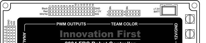
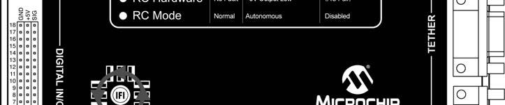
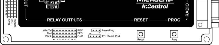
2 Page 2 Table of Contents 1. Robot Controller Overview Main Power Input Battery Backup Power PROGRAM TETHER RADIO PWM Outputs Relay Outputs Analog Inputs Digital Inputs/Outputs Team Color Light Connectors Setting the Team Number Autonomous Mode TTL Serial Port Robot Controller Indicators PROG Button RESET Button RESET/PROG Connectors Circuit Breakers Programming the Robot Controller Appendix A: Document Version History. 15 PWM OUTPUTS (p.6) TEAM COLOR BATTERY BACKUP (p.4 ) (p.10) 12V/GND (p.4) ANALOG INPUTS (p.8) PROGRAM PORT (p.5) TETHER PORT (p.5) DIGITAL I/O (p.9) RS-422 RADIO PORT (p.5) RELAY OUTPUTS (p.7) TTL Serial Port (p.10) REMOTE RESET/PROG (p.13) RESET BUTTON (p.13) PROGRAM BUTTON (p.14) Indicators (p.12)
3 Page 3 1. Robot Controller Overview The Robot Controller (RC) receives information from the Operator Interface, gathers additional information from sensors on-board the robot, determines how the robot should function, and instructs the robot to perform the functions. The Robot Controller also sends data back to the Operator Interface, giving the human operator(s) feedback of critical information. There are 2 types on Robot Controllers, the Full-Size Robot Controller and the EDU Robot Controller. The Full-Size Robot Controller is a large unit with an external Radio Modem. The EDU Robot Controller has fewer inputs and outputs and uses a standard hobby R/C transmitter/receiver pair for remote operation. This document is concerned only with the Full-Size Robot Controller. The Full-Size Robot Controllers gather on-board sensor data via the ANALOG and DIGITAL inputs. There are 16 analog inputs and 18 digital input/output pins on the Full-Size Robot Controller. Switches of various types may be connected to the digital inputs, and external circuitry can be triggered using the digital outputs. Sensors that provide a 0-5V output, such as potentiometers and gyros (yaw rate sensors) may be connected to the analog inputs. The Robot Controller takes the collected data from both the Operator Interface and the on-board sensors and then processes it using its internal microcontrollers. There are two Microchip PIC18F8520 microcontrollers inside the Robot Controller. The first is the Master processor which handles radio and tether communications, generates most of the PWM output signals, and oversees the general operations of the Robot Controller. The second PICmicro is the User processor, and is programmable by the user. The user s program takes the input data, determines what to do with the outputs to make the robot behave as desired, and sets the PWM and Relay outputs to the appropriate states. The Robot Controller comes with a default program that will handle most robot control needs. If more sophisticated control of the robot is desired, then the default program can quickly be modified to provide the required functions of the robot. The Full-Size Robot Controller has 16 PWM outputs and 8 RELAY outputs. The PWM outputs are used to drive Victor 883 speed controllers and servos. The most common use of these outputs is to control a variable speed motor. The PWM outputs will also control most industry standard servos. The Relay outputs are used to drive Spike bi-directional relay modules. The most common use of these outputs, when connected to a Spike, is to drive small motors in Full Forward, Full Reverse or Off. The Relay outputs, in conjunction with a Spike, can also be use to turn On or Off solenoids, pumps, etc. The Robot Controller has an Autonomous Mode, in which the Operator Interface is not needed. The RC will run as programmed in Autonomous Mode, except there is no remote user input, only input from onboard sensors. Reference Documents (available at Size, weight, and mounting info Frequently Asked Questions (FAQs) FIRST Control System Quick Start Guide 2004 FRC Default Code project file Programming Reference Guide
4 Page 4 2. Main Power Input The +12V and GND connectors on the Robot Controller are intended to accept power from a +12V battery. The current draw for the Robot Controller is typically between 0.75A to 1.5A. The maximum voltage allowable is +15.0V. Exceeding the +15.0V limit may damage internal voltage regulators and will void the warranty. The minimum required voltage to maintain radio link is +7.0V. Use circle or U-shaped crimp lugs to connect +12V and GND wires to the Robot Controller. Use a minimum of 16GA wire to minimize voltage drop to the Robot Controller. Fuses prior to the Robot Controller are not required. Always follow FIRST Competition rules when building for FIRST competitions. When wiring to the Robot Controller, ensure that the +12V and GND lugs do not short at the Robot Controller. Connect GND to the corner connector and +12V to the inside connector. The Robot Controller is internally protected from reverse polarity. BACKUP BATTERY GROUND +12V MAIN BATTERY 3. Battery Backup Power Connecting a 7.2V battery to this receptacle will ensure that if the power supply coming in from the Main Power Input drops out or temporarily dips, the Robot Controller will not lose power and reset, causing the program currently running to restart. This can occur if the Robot Controller and the rest of the robot share the same power supply, and a high current draw (from stalled motors, for example) causes that power supply voltage to droop. In this situation the small battery connected to the Battery Backup receptacle will keep the Robot Controller running without resetting when the main power comes back up. The Battery Backup circuit also supplies power to the center pins of the PWM OUTPUTS, which is required to operate servos. The Robot Controller cannot start running from Battery Backup power only. It requires Main power connected at the required voltage to initially power on. If Main is lost and a link with an OI had been established, the RC will continue to operate with only Battery Backup power for approximately 3.5 minutes before it automatically turns itself off. If Main is lost but a link was never established with an OI, the RC will continue to run until the Battery Backup power is exhausted, or until the RESET button is pressed. The Battery Backup connector is intended to accept power from a 7.2V battery. A 7.2V Battery with the proper mating connector is available from
 to connect the PROGRAM port on the Robot Controller to a PC serial port.")
5 Page 5 4. PROGRAM The PROGRAM port is used to change the program on the Robot Controller. This port is intended to connect to a PC s serial port. Use a DB9 Male- Female Pin-to-Pin cable (maximum length 6 ft.) to connect the PROGRAM port on the Robot Controller to a PC serial port. For more details on downloading a new program to the RC, see Section 20 of this document. 5. TETHER The TETHER port is intended to connect the Robot Controller directly to the Operator Interface. Tether is used to communicate to an Operator Interface over a hard wire connection instead of using a wireless radio link. The TETHER port passes the same data as the radios, allowing full functionality without the use of radios. A tether connection can be made with or without Radio Modems connected. The system will always use tether if it is available. When a tether connection is made, you will see the status indicators on the Radio Modems switch to Standby. Both the Operator Interface and the Robot Controller will automatically detect a tether connection and switch to tether without requiring power OFF or a reset. A tether connection also provides power to the Operator Interface from the Robot Controller s +12V battery. Tether power provides a means to power the Operator Interface when 115V 60Hz AC power is not available. Tether power is useful before or after competition rounds to check your system or collapse your robot. Tethering is also required to set the team number of your RC, as detailed in Section 12 of this document. Use a DB9 Female-Female Pin-to-Pin cable (maximum length 6 ft.) to connect the Robot Controller to the Operator Interface. This is different from the standard Male-Female cable used for the Radio port or the Program port. Caution: This port is not intended to interface with a computer. 6. RADIO The port labeled RADIO is intended to connect to the Innovation First RS-422 Robot Controller Radio modem only. This port uses RS-422, instead of RS-232, to minimize noise interference in the communication link. Caution: Do not connect any other equipment to this port. There are two different radios provided with the system. Be sure to connect the Robot Controller to the radio that is marked Robot Controller by the black antenna. Use a DB9 Male-Female Pin-to-Pin cable (maximum length 6 ft.) to connect the Robot Controller to the RS-422 Radio modem.

6 Page 6 7. PWM Outputs The PWM outputs are used to drive Victor 88x series speed controllers and servos on the Full-Size Robot Controller. The most common use of these outputs is to control a variable speed motor from a joystick axis connected to the Operator Interface. The PWM outputs will also control most industry standard servos if a 7.2V backup battery is connected to the Battery Backup connector to power them. Make sure that your servos can handle 7.2V before doing this, however. Each of the PWM outputs generates a unique Pulse Width Modulated (PWM) signal corresponding to a specific output of the User processor s program. Custom User code can be written to control the PWM outputs as desired. Use a PWM/Relay extension cable to connect an appropriate device to one of the PWM output ports. Be sure to connect the cable so the black wire is on the indicated side. A Y-cable can be used on any PWM output to drive two like devices at the same time. Warning: The PWM outputs are only to be used with Victor 88x series Speed Controllers or servos. The use of other speed controllers may damage the unit and will void the warranty. Table 7.5a below shows which of the PWM outputs are controlled by joysticks on the Operator Interface. This table is only valid for Default code. These functions and variable names may be changed for custom user programs. Table 7.5a: PWM Output Map (Default Code Only) PWM Output User Variable Output Controlled by PWM1 p1_y Port 1 joystick Y-axis PWM2 p2_y Port 2 joystick Y-axis PWM3 p3_y Port 3 joystick Y-axis PWM4 p4_y Port 4 joystick Y-axis PWM5 p1_x Port 1 joystick X-axis PWM6 p2_x Port 2 joystick X-axis PWM7 p3_x Port 3 joystick X-axis PWM8 p4_x Port 4 joystick X-axis PWM9 p1_wheel Port 1 joystick Wheel PWM10 p2_wheel Port 2 joystick Wheel PWM11 p3_wheel Port 3 joystick Wheel PWM12 p4_wheel Port 4 joystick Wheel PWM13 mixing function Port 1 joystick Y & X axes mixed PWM14 mixing function Port 1 joystick Y & X axes mixed PWM15 mixing function Port 1 joystick Y & X axes mixed PWM16 mixing function Port 1 joystick Y & X axes mixed Note: Twelve Robot Controller digital inputs are configured by the default code to act as limit switches for PWMs 3, 4, Refer to Section 10 on page 9 for more details. PWMs are meant to be used if one desires to control the robot using only one joystick. The left and right drive motors are controlled by mixing the X and Y axes of joystick 1.

7 Page 7 8. Relay Outputs The Relay outputs of the Full-size Robot Controller are used to drive Spike bi-directional relay modules. The most common use of these outputs, when connected to a Spike, is to drive small motors in Full Forward, Full Reverse or Off. The Relay outputs, in conjunction with a Spike, can also be use to turn On or Off solenoids, pumps, and lights from a joystick button on the Operator Interface. Each of the eight ports generates two binary signals corresponding to a specific output of the User program. Custom User software can be used to control the Relay outputs as desired. Refer to the Spike Users Manual (available at for detailed instructions on wiring to motors, solenoids, pumps, and lights. Use a PWM/Relay extension cable to connect a Spike to one of the Relay outputs. Be sure to connect the cable so that the black wire is on the indicated side. Each Relay output can be used with a Y-cable to drive two Spikes from the same output. NOTE: The REV/FWD silkscreen labels on the unit are incorrect. They should be swapped. Table 7.6 below shows which of the Relay outputs are controlled by joysticks connected to the Operator Interface. This table is only valid for Default code. These functions and variable names may be changed in custom user programs. Refer to the Programming Reference Guide available at for details on making such changes. Table 7.6: Relay Output Map (Default Code Only) Relay Operator Interface Connector Pin Operator Interface Control Switch User code Variable Relay 1 Forward OI Port 1 2 Joystick Trigger Switch p1_sw_trig Relay 1 Reverse OI Port 1 7 Joystick Thumb Switch p1_sw_top Relay 2 Forward OI Port 2 2 Joystick Trigger Switch p2_sw_trig Relay 2 Reverse OI Port 2 7 Joystick Thumb Switch p2_sw_top Relay 3 Forward OI Port 3 2 Joystick Trigger Switch p3_sw_trig Relay 3 Reverse OI Port 3 7 Joystick Thumb Switch p3_sw_top Relay 4 Forward OI Port 4 2 Joystick Trigger Switch p4_sw_trig Relay 4 Reverse OI Port 4 7 Joystick Thumb Switch p4_sw_top Relay 5 Forward OI Port 1 10 Auxiliary OI Digital Input (unwired to joystick) p1_sw_aux1 Relay 5 Reverse OI Port 1 11 Auxiliary OI Digital Input (unwired to joystick) p1_sw_aux2 Relay 6 Forward OI Port 2 10 Auxiliary OI Digital Input (unwired to joystick) p2_sw_aux1 Relay 6 Reverse OI Port 2 11 Auxiliary OI Digital Input (unwired to joystick) p2_sw_aux2 Relay 7 Forward OI Port 3 10 Auxiliary OI Digital Input (unwired to joystick) p3_sw_aux1 Relay 7 Reverse OI Port 3 11 Auxiliary OI Digital Input (unwired to joystick) p3_sw_aux2 Relay 8 Forward OI Port 4 10 Auxiliary OI Digital Input (unwired to joystick) p4_sw_aux1 Relay 8 Reverse OI Port 4 11 Auxiliary OI Digital Input (unwired to joystick) p4_sw_aux2 Note: Four Robot Controller digital inputs are configured by the default code to act as limit switches for Relay 1 and Relay 2. Refer to Section 10 on page 9 for more details.

8 Page 8 9. Analog Inputs The analog inputs on the Robot Controller can be used to measure various conditions on the robot and trigger automatic responses by the control program. There are 16 analog inputs available on the ANALOG INPUTS connectors on the Full-Size Robot Controller. Any sensor which outputs a variable 0-5V signal may be read with 10-bit resolution on these inputs. Popular devices include potentiometers and gyro (yaw rate) sensors. Potentiometers should be wired per the diagram below when connecting to the Analog Inputs. Always use 100kΩ potentiometers. For wiring yaw rate sensors, refer to the sensor manufacturer s data sheet. Connecting a potentiometer to an Analog Input Analog Input (White) +5V Output (Red) Ground (Black) 100kΩ For details on reading and using values from the Analog Inputs, refer to the Innovation First Programming Reference Guide.

9 Page Digital Inputs/Outputs The 18 Digital I/O pins on the Robot Controller can be configured individually as either inputs or outputs in the User program. For details on configuring them in software, refer to the Innovation First Programming Reference Guide. When configured as inputs these pins accept signals of either 0 Volts or 5 Volts from sources such as switches or other external circuitry. A 0V signal will be read as a logic 0 in the software, and a 5V signal on the pin will be read as a logic 1. A 5V signal is not required because these pins are all pullups, which means that if left disconnected from any external signal, they will be pulled high to 5V. This means that all unconnected digital inputs will be read as a logic 1 in the software. The most common use for digital inputs is for the connection of switches. Wire switches between the desired digital input signal pin and a ground pin. Digital inputs in the Default Code are looking only for ground signals to become active. Switches may be wired individually, in parallel, or in series. For advanced users, the first six digital I/O pins can be configured as hardware interrupts. While powerful, this feature can cause undesired operation if improperly used. Therefore Innovation First will not provide support for this feature. More details on using interrupts can be found by referring to the 18F8520 microcontroller datasheet and the MPLAB C18 C Compiler User s Guide. The Default Code has an interrupt handler written for these pins, but you must still configure and enable the interrupts to use them. Table 7.8: Digital Input/Output Pinout and Software Function Pin Function C Variable Alias C Default Code Function 1 Switch 1 rc_dig_in01 Relay 1 won t go Forward if rc_sw1 is ON 2 Switch 2 rc_dig_in02 Relay 1 won t go Reverse if rc_sw2 is ON 3 Switch 3 rc_dig_in03 Relay 2 won t go Forward if rc_sw3 is ON 4 Switch 4 rc_dig_in04 Relay 2 won t go Reverse if rc_sw4 is ON 5 Switch 5 rc_dig_in05 PWM 3 won t go Forward if rc_sw5 is ON 6 Switch 6 rc_dig_in06 PWM 3 won t go Reverse if rc_sw6 is ON 7 Switch 7 rc_dig_in07 PWM 4 won t go Forward if rc_sw7 is ON 8 Switch 8 rc_dig_in08 PWM 4 won t go Reverse if rc_sw8 is ON 9 Switch 9 rc_dig_in09 PWM 9 won t go Forward if rc_sw9 is ON 10 Switch 10 rc_dig_in10 PWM 9 won t go Reverse if rc_sw10 is ON 11 Switch 11 rc_dig_in11 PWM 10 won t go Forward if rc_sw11 is ON 12 Switch 12 rc_dig_in12 PWM 10 won t go Reverse if rc_sw12 is ON 13 Switch 13 rc_dig_in13 PWM 11 won t go Forward if rc_sw13 is ON 14 Switch 14 rc_dig_in14 PWM 11 won t go Reverse if rc_sw14 is ON 15 Switch 15 rc_dig_in15 PWM 12 won t go Forward if rc_sw15 is ON 16 Switch 16 rc_dig_in16 PWM 12 won t go Reverse if rc_sw16 is ON 17 Output rc_dig_out17 18 Output rc_dig_out18

10 Page Team Color Light Connectors There are four team color connectors which all output identical signals. Each connector is meant to drive one team color LED unit for identifying which team your robot is on. Team color LED units are included in your kit or are available from Innovation First. By default, these LED units will display red if you are using the default practice channel of 40. If you use a channel adapter to change to another radio channel, the team color will differ. Channels 4, 22, and 40 will cause a red team color to flash, while channels 13 and 31 cause blue. In general, the user cannot control the team color, because it is set by the Arena Controller during competition. 12. Setting the Team Number Unlike previous Innovation First Robot Controllers, the current system does not have any dip-switches for setting the Team Number. In order to set the Robot Controller s Team Number, you must first set the Team Number on the Operator Interface, then connect the OI and RC using a tether cable. The Robot Controller will automatically read the Team Number from the OI and will store it internally in EEPROM. The Team Number will be remembered even if the Robot Controller s power is turned off. For instructions on setting the team number using the DIP switches on the OI, please refer to the Operator Interface Reference Guide. 13. Autonomous Mode Autonomous Mode means that the RC will ignore all data from the Operator Interface and it will not require a link with the Operator Interface to execute code. If you wish to run the Robot Controller exclusively in Autonomous Mode, one way to do this is to set your team number to zero. This is done by setting the team number on your OI to zero, linking your OI and RC by tether, and then disconnecting from tether. After your RC is reset it will be in Autonomous Mode. To exit Autonomous mode if your team number is zero, you must re-tether and change the team number to anything but zero. An additional method for getting into Autonomous Mode is described in the Operator Interface Reference Guide in the Competition Control LED section. See the Programming Reference Guide for details on how to program for Autonomous Mode.
11 Page TTL Serial Port The four-pin header labeled TTL Serial Port is an auxiliary serial port from the User processor inside the Robot Controller. The PROGRAM connector is actually the User processor s Serial Port 1, with circuitry to convert the TTL level signal to RS-232 levels so that it can be interfaced with a standard PC serial port. The TTL Serial Port connector is the User processor s Serial Port 2, but without any conversion. This enables the Robot Controller to use serial communications with other TTL-level digital circuitry. If it is necessary to use this serial port to communicate with RS-232 devices (such as a PC), various TTL to RS-232 adapters can be purchased from the internet, or plans to make one s own are also available from the internet. Both Serial Port 1 and Serial Port 2 are available to the user through custom programs. While Innovation First does not support this feature, general programming information can be found in the Programming Reference Guide from the Innovation First web site, and more specifics on the Microchip PIC18F8520 microcontroller can be found in the datasheet from Microchip s web site. Note that no dedicated handshaking lines are provided, but any of the digital I/O lines could be used for this purpose in software, if necessary. TTL Serial Port Pin-out + (5V) TX RX B (GND)
12 Page Robot Controller Indicators The Robot Controller has the following LED indicators, as labeled on the RC cover. Table 8.2: Robot Controller LEDs Battery Power Green Input power from Main battery is ON from +12V/GND. Voltage reads between approximately 9.2V to 12V. Battery Power Yellow Low main input voltage detected. Replace or recharge main battery soon, if used. Voltage reads between approximately 7.2V to 9.1V. Battery Power Yellow solid Main battery voltage is below backup battery voltage. RC is now being powered by backup battery. Replace or recharge main battery soon, if used. Battery Power Red Very low input voltage detected. If running from a battery, the RC is about to power down. Voltage reads between approximately 5.7V to 7.1V. Battery Power Red Main and backup batteries are dead. RC is shut down. Voltage is below 5.7V. solid Program State Green Normal operation. User processor is executing code. Program State Yellow solid Ready for bootload. Waiting for new program to be downloaded from the PC. PROG button was pressed on the Robot Controller. Program State Yellow Downloading new program from the PC. Program State Red User processor is being held in reset due to a code violation or an infinite loop. Check code. Re-download the Default Code to help verify a coding problem. Radio Modem Green Normal link between Robot Controller and Operator Interface. Radio Modem Yellow Data is being missed between RC and OI. Possible causes include interference on the channel or the radios are out of range. Radio Modem Yellow Searching for radio link to an OI with the same team number. solid Radio Modem Red Link to OI has been lost, either by tether or radio. Radio Modem Red Radio Modem not found. Check modem and cables. solid RC Hardware Off No backup battery is connected. RC Hardware Green Normal operation. RC Hardware Yellow solid Internal 5V power for analog and digital I/O supply is in a high current condition. Check for shorts on pins. RC Hardware Red Backup battery voltage is low (below approximately 5.9V). solid RC Mode Off RC is disabled and waiting to link to an OI. RC Mode Green RC is linked to an OI and operating normally. RC Mode Yellow RC is in Autonomous mode because of commands from an OI or Arena Controller. RC Mode Red RC has been disabled by the OI or the Arena Controller.

13 Page PROG Button The PROG button stops the User code from executing and puts the Robot Controller into a standby state in which it is waiting for new code to be downloaded from a PC. In this state the currently executing program will be stopped and the PROGRAM STATE LED will turn a solid yellow. See Section 20 for more information on downloading new code to the Robot Controller. For most PCs it is not necessary to press this button before downloading new code; it can be downloaded simply by clicking the Download button in the IFI Loader software running on the PC. The serial ports on some PCs, however, may not correctly support this feature. In such a case it is necessary to press the PROG button on the RC to prepare it for downloading from the PC. 17. RESET Button The RESET button performs a complete hardware reset of the Robot Controller, including the Master and User processors. Resetting also re-initializes the external radio to Search or channel scan mode. Power cycling the Robot Controller and pressing the RESET button both have the same result. The most common use for the RESET button is to restart the User processor in case of a programming error which has resulted in an infinite loop. If the Robot Controller is running from Battery Backup power, you must press the RESET button to power off the RC after Main power is removed. 18. RESET/PROG Connectors The three pins labeled Reset/Prog enable the user to remotely trigger a reset or download event. Connecting either the RESET (left) pin or the PROG (center) pin to the ground (right) pin would appear to the Robot Controller as if either the RESET or PROG buttons were pressed, respectively. This feature has been included so that wires can be run to remote buttons, switches, or circuitry for more convenient triggering if the buttons are inaccessible or buried in your robot. Remember that RESET is necessary to power down your RC when using Battery Backup. 19. Circuit Breakers The Robot Controller has two internal auto resetting circuit breakers. One protects Tether power and Team Color power from short circuits. This circuit breaker will trip when current exceeds 1.5 amps. The other circuit breaker protects the Battery Backup circuit. This circuit breaker will trip when current exceeds 4 amps. The center pin of the PWM OUTPUTS is connected to the Battery Backup circuit. This center pin is typically used to power servos.
14 Page Programming the Robot Controller The Robot Controller is supplied with a Default program written using the C programming language in order to help get the robot up and running quickly. If more sophisticated control of the robot is desired, then a custom program can be quickly created by modifying the Default program. In order to facilitate the creation of a custom program, source code for the Default program is provided. The Default program project file is available at For complete details on creating custom programs for the Robot Controller, see the Programming Reference Guide. The software necessary for writing a custom program are as follows: MPLAB IDE and C18 compiler from the C-Bot CD-ROM. IFI Loader available from the C-Bot CD-ROM or Once a custom program has been created and compiled according to the instructions in the Programming Reference Guide, the resulting.hex file must be downloaded to the Robot Controller. Brief instructions for doing this are below. For detailed steps, refer to the Programming Reference Guide. 1. Compile a valid program in MPLAB IDE. You may also use the FRC_Default.hex file which has been pre-compiled to restore the default functionality. 2. Power ON the Robot Controller. 3. Connect a DB9 Male-to-Female Pin-to-Pin cable from the PROGRAM port to PC s serial port. 4. Run IFI Loader on the PC. 5. Click the Browse button and select the desired.hex file. 6. Click the DOWNLOAD button in IFI Loader. 7. Wait for download to complete. Before the new User program will start executing, a full-size FRC Robot Controller must have a Valid RX (link) to an OI or the RC must be in Autonomous Mode. Successful Programming: PROGRAM STATE LED Green After programming the Robot Controller, the Robot Controller must link to an Operator Interface using either tether or radio before the new code will begin executing. Once a proper link has been established, you should see the PROGRAM STATE LED flashing green. This indicates that the new program is running. Programming Problem: PROGRAM STATE LED Red If after programming and linking to an OI, the PROGRAM STATE LED is flashing red, there is a problem with the code that was downloaded. Possible causes include incorrect initialization of the microcontroller, the code loop taking too long to execute, or the code getting stuck in an infinite loop. Check for errors in the code. If any of these conditions occur, the Master processor will hold the entire Robot Controller in a reset state so that erratic operation does not occur. If you are using the Dashboard Viewer software from Innovation First s web site, you can view the warning code which will tell you more details about the violation which caused the error.
15 Page 15 Appendix A: Document Version History Date Code Changes p.7 Added note regarding incorrect Relay REV/FWD labels on units p.11 Added TTL Serial Port Pin-out diagram p.12 RC Hardware Yellow changed to Yellow solid Initial document release.
Innovation First, Inc. Operator Interface Reference Guide
 11.8.2002 www.innovationfirst.com Page 2 Table of Contents 1. Operator Interface Basics...3 2. Input Power...4 3. RS-422 Radio...4 4. Operator Interface Ports 1, 2, 3, and 4...4 5. Tether Port...11 6.
Innovation First, Inc Programming Reference Guide
 4.12.2004 www.innovationfirst.com Page 2 Table of Contents 1. PICmicro Processor and Memory...3 1.1. Processors... 3 1.2. PICmicro MCU Program Memory... 3 1.3. Default vs. Custom Programs... 3 1.4. Programming
CORTEX Microcontroller and Joystick User Guide
 This is a User Guide for using the VEX CORTEX Microcontroller and VEX Joystick. Refer to the VEX Wiki (http://www.vexforum.com/wiki/index.php/vex_cortex_microcontroller) for updates to this document. 1.
Pridgen Vermeer Robotics ATmega128 Revision 0
 Features: 6x 8-bit I/O Ports 4x A/D Inputs 6x PWM Headers 2x RS 232 Terminals Power Bus LCD Header (4-bit mode) Smart Power Connecter Power Switch Header Power LED Debug LED Note: Some pins have multiple
This is an inspection failure, not meeting the requirement of >10k Ohm between either PD battery post and chassis.
 Troubleshooting This is a document put together by CSA Laura Rhodes that contains a lot of information about troubleshooting steps for a lot of common control system problems encountered at events. No
VEX ARM Cortex -based Microcontroller and VEXnet Joystick User Guide
 1. VEX ARM Cortex -based Microcontroller and VEXnet Joystick Pairing Procedure: a. The Joystick must first be paired to the VEX ARM Cortex -based Microcontroller before they will work using VEXnet Keys.
Electronics Workshop. Jessie Liu
 Electronics Workshop Jessie Liu 1 Return Kit Servos Servo Extensions Controller Analog USB/Tether Serial WiFi key (2) (2) Digital i/o Servo Power Adaptor AAA Battery Charger motors/ servos (4) Servo Mounting
INTRODUCTION TABLE OF CONTENTS 1 INTRODUCTION WELCOME TO THE 2009 FRC CONTROL SYSTEM Suggestions for Getting Started 2
 Section 1 INTRODUCTION TABLE OF CONTENTS 1 INTRODUCTION 2 1.1 WELCOME TO THE 2009 FRC CONTROL SYSTEM 2 1.1.1 Suggestions for Getting Started 2 1.2 TECHNICAL SUPPORT FOR THE 2009 FRC CONTROL SYSTEM 2 1.3
Cheap Control Systems. Cheap Six Channel (C6C) Servo Controller Version 2.3 OVERVIEW
 Servo Controller Version 2.3 OVERVIEW") Cheap Control Systems Cheap Six Channel (C6C) Servo Controller Version 2.3 The Cheap Six Channel (C6C) Servo Controller is a low cost embedded controller that allows the Sony Playstation 2 (PS2) game pad
Cheap Control Systems Cheap Six Channel (C6C) Servo Controller Version 2.3 The Cheap Six Channel (C6C) Servo Controller is a low cost embedded controller that allows the Sony Playstation 2 (PS2) game pad
Intelligent Devices IDI 1100 Series Technical Manual
 Intelligent Devices IDI 1100 Series 4411 Suwanee Dam Road, Suite 510 Suwanee, GA 30024 T: (770) 831-3370 support@intelligentdevicesinc.com Copyright 2011, Intelligent Devices, Inc. All Rights Reserved
Embedded Navigation Solutions VN 100, VN 200 & VN 300 Development Board User Manual
 Embedded Navigation Solutions VN 100, VN 200 & VN 300 Development Board User Manual VectorNav Technologies Contact Info 10501 Markison Road Phone +1 512 772 3615 Dallas, Texas 75238 Email support@vectornav.com
BEST Control System. Dave Wilkerson. September 12, 2015
 BEST Control System BEST Robotics, Inc. Dave Wilkerson September 12, 2015 Copyright 2012 BEST Robotics, Inc. All rights reserved. 1 Servos Joystick Return Kit AAA Battery Charger Analog WiFi key USB/Tether
EZ-Bv4 Datasheet v0.7
 EZ-Bv4 Datasheet v0.7 Table of Contents Introduction... 2 Electrical Characteristics... 3 Regulated and Unregulated Power Pins... 4 Low Battery Warning... 4 Hardware Features Main CPU... 5 Fuse Protection...
Pridgen Vermeer Robotics Xmega128 Manual
 Features: 12x PWM signals with 5V supply 8x A/D Inputs with 3.3V supply 2x RS 232 Terminals 1x SPI Interface 4x 8-bit Digital IO ports 3.3V Power Bus LCD Header (4-bit mode) Smart Power Connecter Power
RoboClaw 2x30A Dual Channel Motor Controller
 RoboClaw 2x30A, 34VDC Dual Channel Brushed DC Motor Controller Version 2.2 (c) 2016 Ion Motion Control. All Rights Reserved. Feature Overview: 60 Amps Peak Per Channel Channel Bridging Supported Dual Quadrature
Basic Express, BasicX, BX-01, BX-24 and BX-35 are trademarks of NetMedia, Inc.
 1997-2002 by NetMedia, Inc. All rights reserved. Basic Express, BasicX, BX-01, BX-24 and BX-35 are trademarks of NetMedia, Inc. Microsoft, Windows and Visual Basic are either registered trademarks or trademarks
AX1500. Dual Channel Digital Motor Controller. Quick Start Manual. v1.9b, June 1, 2007
 AX1500 Dual Channel Digital Motor Controller Quick Start Manual v1.9b, June 1, 2007 visit www.roboteq.com to download the latest revision of this manual Copyright 2003-2007 Roboteq, Inc. SECTION 1 Important
PHASED OUT PRODUCT DC2. Microcontroller DESCRIPTION FEATURES ORDERING INFORMATION. BLN Issued: June 1995
 DESCRIPTION DC2 Microcontroller Danfoss DC2 Microcontroller is a multi-loop controller that is environmentally hardened for mobile off-highway control system applications. The DC2 Microcontroller has the
MP6500 Stepper Motor Driver, Digital Current Control
 This breakout board for the MPS MP6500 micro stepping bipolar stepper motor driver is Pololu s latest stepper motor driver. The module has a pinout and interface that are very similar to that of our popular
UNIVERSAL MOTION INTERFACE (UMI) ACCESSORY
 ACCESSORY") USER GUIDE UNIVERSAL MOTION INTERFACE (UMI) ACCESSORY Contents This user guide describes how to use the UMI-77, UMI-A, UMI-Flex, and UMI-Flex accessories. Introduction... What You Need to Get Started...
USER GUIDE UNIVERSAL MOTION INTERFACE (UMI) ACCESSORY Contents This user guide describes how to use the UMI-77, UMI-A, UMI-Flex, and UMI-Flex accessories. Introduction... What You Need to Get Started...
Bolt 18F2550 System Hardware Manual
 1 Bolt 18F2550 System Hardware Manual Index : 1. Overview 2. Technical specifications 3. Definition of pins in 18F2550 4. Block diagram 5. FLASH memory Bootloader programmer 6. Digital ports 6.1 Leds and
Hybrid AC Driver [GCNC-1110]
![Hybrid AC Driver [GCNC-1110]](/thumbs/86/94474371.jpg "Hybrid AC Driver [GCNC-1110]") Page 1 Installation Manual and Datasheet Page 2 Key Features Smooth and quiet operation at all speeds and extremely low motor heating Industrial grade performance for an alternating current servo motor
Page 1 Installation Manual and Datasheet Page 2 Key Features Smooth and quiet operation at all speeds and extremely low motor heating Industrial grade performance for an alternating current servo motor
RoboClaw 120A/160A/200A Dual Channel Motor Controller
 RoboClaw 2x160A, 34VDC Dual Channel RoboClaw 2x120AHV, 60VDC Dual Channel RoboClaw 2x160AHV, 60VDC Dual Channel RoboClaw 2x200AHV, 60VDC Dual Channel Brushed DC Motor Controllers Version 2.1 (c) 2016 Ion
USER MANUAL FOR HARDWARE REV
 PI-REPEATER-2X 1. WELCOME 2. CONTENTS PAGE 1 3. GETTING STARTED There are many features built into this little board that you should be aware of as they can easily be missed when setting up the hardware
LCMM024: DRV8825 Stepper Motor Driver Carrier,
 LCMM024: DRV8825 Stepper Motor Driver Carrier, High Current The DRV8825 stepper motor driver carrier is a breakout board for TI s DRV8825 microstepping bipolar stepper motor driver. The module has a pinout
keyestudio Keyestudio MEGA 2560 R3 Board
 Keyestudio MEGA 2560 R3 Board Introduction: Keyestudio Mega 2560 R3 is a microcontroller board based on the ATMEGA2560-16AU, fully compatible with ARDUINO MEGA 2560 REV3. It has 54 digital input/output
USER S MANUAL. C33 - MULTIFUNCTION ROUTER BOARD BOARD Rev. 4
 USER S MANUAL C33 - MULTIFUNCTION ROUTER BOARD BOARD Rev. 4 June 2013 USER'S MANUAL TABLE OF CONTENTS Page # Contents 1.0 OVERVIEW... 3 2.0 FEATURES... 3 3.0 SPECIFICATIONS... 4 4.0 FUNCTIONAL BLOCK DIAGRAMS...
INSTALLATION AND OPERATING INSTRUCTIONS DSST SYSTEM
 INSTALLATION AND OPERATING INSTRUCTIONS DSST SYSTEM PROPORTIONAL and NON-PROPORTIONAL TOGGLE SWITCH RADIO REMOTE CONTROL SYSTEM MODEL FHSTP/DSSTP SERIES FHST/DSST SYSTEM DESCRIPTION The DSST Wireless Control
Cheap Control Systems. Cheap Twelve Channel (C12C) Servo Controller Version 1.0 OVERVIEW
 Servo Controller Version 1.0 OVERVIEW") Cheap Control Systems Cheap Twelve Channel (C12C) Servo Controller Version 1.0 The Cheap Twelve Channel (C12C) Servo Controller is a low cost embedded controller that allows a Sony Playstation 2 (PS2)
Cheap Control Systems Cheap Twelve Channel (C12C) Servo Controller Version 1.0 The Cheap Twelve Channel (C12C) Servo Controller is a low cost embedded controller that allows a Sony Playstation 2 (PS2)
MC300. BLN Issued: April 2003
 MC300 Microcontroller Issued: April 2003 DESCRIPTION The MC300 Microcontroller is a multi-loop controller that is environmentally hardened for mobile off-highway control system applications. The MC300
Prop-SX Controller PN: 31103
 Prop-SX Controller PN: 31103 Document Version: 1.1 18 DEC 2007 Copyright 2007 EFX-TEK DESCRIPTION The Prop-SX is a small-scale controller designed to meet the needs to prop builders, effects technicians,
BEST Generic Kit Notes GMKR00002 Revision 7; August 2011
 GMKR00002 Revision 7; August 2011 1.0 Introduction This document is for information only. Although it is consistent with the rules, please see the Generic Game Rules document for the official rules. All
GUIDE TO SP STARTER SHIELD (V3.0)
") OVERVIEW: The SP Starter shield provides a complete learning platform for beginners and newbies. The board is equipped with loads of sensors and components like relays, user button, LED, IR Remote and
OVERVIEW: The SP Starter shield provides a complete learning platform for beginners and newbies. The board is equipped with loads of sensors and components like relays, user button, LED, IR Remote and
C33- MULTIFUNCTION ROUTER BOARD Rev. 2
 C33- MULTIFUNCTION ROUTER BOARD Rev. 2 User manual Rev. 1 1. Overview This card provides an easy way of interfacing your router based spindle with your steeper motor driver board. This board includes a
Goal: We want to build an autonomous vehicle (robot)
") Goal: We want to build an autonomous vehicle (robot) This means it will have to think for itself, its going to need a brain Our robot s brain will be a tiny computer called a microcontroller Specifically
Goal: We want to build an autonomous vehicle (robot) This means it will have to think for itself, its going to need a brain Our robot s brain will be a tiny computer called a microcontroller Specifically
Instruction Manual for BE-SP3 Circuit. 10/21/07
 Page 1 of 54 Instruction Manual for BE-SP3 Circuit. 10/21/07 Page 1 Index: Page 2 BE-SP3 Circuit Specifications. Page 3-4 Intro to the BE-SP3. Page 5 Basics of serial to parallel. Page 6-7 ASCII Code.
DC3IOB Revision User Guide Updated 3/29/10. Overview
 Revision 080910 User Guide Updated 3/29/10 Overview The is a three axis DC brush motor drive with an integrated PLC. A range of motor drive currents are selectable with jumper blocks. The integrated PLC
C10- PARALLEL PORT INTERFACE CARD Rev. 8
 C10- PARALLEL PORT INTERFACE CARD Rev. 8 User manual Rev. 1 1. Overview This card provides an easy way of interfacing your inputs and outputs from you parallel port. It provides terminals for the connections
MX Educational Target User Manual
 MX Educational Target User Manual Revision History Date Description Initial release. Table of Contents 1. Introduction... 4 1.1. Module Models... 4 1.2. Package Contents... 4 1.3. Key Hardware Features...
Security and Convenience Components 519H Three-Channel Receiver
 Security and Convenience Components 519H Three-Channel Receiver FCC/ID Notice This device complies with Part 15 of FCC rules. Operation is subject to the following two conditions: (1) This device may not
Rover 5. Explorer kit
 Rover 5 Explorer kit The explorer kit provides the perfect interface between your Rover 5 chassis and your micro-controller with all the hardware you need so you can start programming right away. PCB Features:
ARDUINO MINI 05 Code: A000087
 ARDUINO MINI 05 Code: A000087 The Arduino Mini is a very compact version of the Arduino Nano without an on board USB to Serial connection The Arduino Mini 05 is a small microcontroller board originally
Prop-2 Controller PN: 31102
 Prop-2 Controller PN: 31102 Document Version: 1.2 18 DEC 2007 Copyright 2007 EFX-TEK DESCRIPTION The Prop-2 is a small-scale controller designed to meet the needs to prop builders, effects technicians,
Dwarf Boards. DN001 : introduction, overview and reference
 Dwarf Boards DN001 : introduction, overview and reference (c) Van Ooijen Technische Informatica version 1.6 PICmicro, In-Circuit Serial Prograing and ICSP are registerd trademarks of Microchip Technology
CDN502 HIGH DENSITY I/O ADAPTER USER GUIDE
 CDN502 HIGH DENSITY I/O ADAPTER USER GUIDE 13050201 (c) Copyright DIP Inc., 1996 DIP Inc. P.O. Box 9550 MORENO VALLEY, CA 92303 714-924-1730 CONTENTS DN502 PRODUCT OVERVIEW 1 DN502 INSTALLATION 1 POWER
Prop-1 Controller PN: 31101
 Prop-1 Controller PN: 31101 Document Version: 2.3 18 DEC 2007 Copyright 2006-2007 DESCRIPTION The Prop-1 is a small-scale controller designed to meet the needs to prop builders, effects technicians, and
USER S MANUAL. C32- DUAL PORT MULTIFUNCTION CNC BOARD Rev. 4
 USER S MANUAL C32- DUAL PORT MULTIFUNCTION CNC BOARD Rev. 4 August, 2012 USER'S MANUAL TABLE OF CONTENTS Page # 1.0 FEATURES... 1-1 2.0 SPECIFICATIONS... 2-3 3.0 BOARD DESCRIPTION... 3-4 4.0 FUNCTIONAL
e-ask electronic Access Security Keyless-entry RF Keyless-entry entry System TM-Multi Multi Installation Manual FCC ID: TV2EFOB1 (UM21 ~ )
") e-ask electronic Access Security Keyless-entry e-fob RF Keyless-entry entry System TM-Multi Multi Installation Manual FCC ID: TV2EFOB1 (UM21 ~ 22795-01) Table of Contents Introduction... 1 e-fob Operation
e-ask electronic Access Security Keyless-entry e-fob RF Keyless-entry entry System TM-Multi Multi Installation Manual FCC ID: TV2EFOB1 (UM21 ~ 22795-01) Table of Contents Introduction... 1 e-fob Operation
BEST Generic Kit Notes GMKR00002 Revision 5; August 2010
 GMKR00002 Revision 5; 1.0 Introduction All Returnable Kit items, including boxes and packing, must be returned at the conclusion of the contest. This equipment will be used again next year; so do not modify
UNIVERSAL MOTION INTERFACE (UMI) ACCESSORY
 ACCESSORY") USER GUIDE UNIVERSAL MOTION INTERFACE (UMI) ACCESSORY Introduction This user guide describes how to use the UMI-A, UMI-Flex, and UMI-Flex accessories. The UMI products are connectivity accessories you
USER GUIDE UNIVERSAL MOTION INTERFACE (UMI) ACCESSORY Introduction This user guide describes how to use the UMI-A, UMI-Flex, and UMI-Flex accessories. The UMI products are connectivity accessories you
HomeVision-Pro Overview for HomeVision Users
 HomeVision-Pro Overview for HomeVision Users This document has two main purposes: 1. To describe the main differences between HomeVision and HomeVision-Pro. 2. To assist HomeVision users in converting
RFID: Read and Display V2010. Version 1.1. Sept Cytron Technologies Sdn. Bhd.
 PR8-B RFID: Read and Display V2010 Version 1.1 Sept 2010 Cytron Technologies Sdn. Bhd. Information contained in this publication regarding device applications and the like is intended through suggestion
EATON 5S 850/1200/1600
 www.eaton.com EATON 5S 850/1200/1600 Installation and user manual Packaging EATON 5S 1 2 3 5 Caution! l Before installing the Eaton 5S, read the booklet 3 containing the safety instructions to be respected.
ASTRO-PHYSICS GTO CONTROL BOX FOR SERVO DRIVE Model GTOCP1
 ASTRO-PHYSICS GTO CONTROL BOX FOR SERVO DRIVE Model GTOCP1 GTO CONTROL BOX GTOCP1 The GTO control box contains all of the circuitry to drive the two servo motors and the logic required to navigate the
IS-S0108 Single Switch Solution
 IS-S0108 Single Switch Solution IS-S0108 Single Switch Solution Revision D NKK SWITCHES 7850 E. Gelding Drive Scottsdale, AZ 85260 Toll Free 1-877-2BUYNKK (877-228-9655) Phone 480-991-0942 Fax 480-998-1435
BEST Generic Kit Usage Guide GMKR00002 Revision 9; August 2013
 GMKR00002 Revision 9; August 2013 1.0 Introduction This document is for information only. Although it is consistent with the rules, please see the Generic Game Rules document for the official rules. All
G540 MANUAL MULTIAXIS STEP MOTOR DRIVE
 G540 MANUAL MULTIAXIS STEP MOTOR DRIVE PRODUCT DIMENSIONS PHYSICAL AND ELECTRICAL RATINGS Minimum Maximum Units Supply Voltage 18 50 VDC Motor Current 0 3.5 A Power Dissipation 1 13 W Short Circuit Trip
FEATURES DESCRIPTION FEATURES
 FEATURES Two High Speed Counters Two Pulse Train Outputs Two Pulse Width Modulation Outputs 24 Sinking or Sourcing Inputs 16 Outputs 1 RS232 Port 2 RS485 Ports Supports Modbus RTU Protocol Communicate
Breeze Board. Type A. User Manual.
 Breeze Board Type A User Manual www.dizzy.co.za Contents Introduction... 3 Overview Top... 4 Overview Bottom... 5 Getting Started (Amicus Compiler)... 6 Power Circuitry... 7 USB... 8 Microcontroller...
CDN503 HIGH DENSITY I/O ADAPTER USER GUIDE
 CDN503 HIGH DENSITY I/O ADAPTER USER GUIDE 13050301 (c) Copyright DIP Inc., 1996 DIP Inc. P.O. Box 9550 MORENO VALLEY, CA 92303 714-924-1730 CONTENTS DN503 PRODUCT OVERVIEW 1 DN503 INSTALLATION 1 POWER
C35- QUICK SETUP BREAKOUT BOARD Rev. 1.1
 C35- QUICK SETUP BREAKOUT BOARD Rev. 1.1 User manual Rev. 1 1. Overview This card provides an easy way of interfacing your inputs and outputs from the parallel port. It provides terminals and RJ45 for
Hardware Manual 1240i-485
 Hardware Manual -485 Intelligent Step Motor Driver with Multi-drop RS-485 Interface 920-0033 A 7/6/2010 motors drives controls -2- Table of Contents Introduction...4 Features...4 Block Diagram...4 Getting
2Installation CHAPTER TWO IN THIS CHAPTER. Checking Your Shipment Express Setup. Chapter 2 Installation 11
 CHAPTER TWO 2Installation IN THIS CHAPTER Checking Your Shipment Express Setup Chapter 2 Installation 11 Checking Your Shipment Inspect your shipment carefully. You should have received one or more of
Propeller Activity Board (#32910)
") Web Site: www.parallax.com Forums: forums.parallax.com Sales: sales@parallax.com Technical: support@parallax.com Office: (916) 624-8333 Fax: (916) 624-8003 Sales: (888) 512-1024 Tech Support: (888) 997-8267
Web Site: www.parallax.com Forums: forums.parallax.com Sales: sales@parallax.com Technical: support@parallax.com Office: (916) 624-8333 Fax: (916) 624-8003 Sales: (888) 512-1024 Tech Support: (888) 997-8267
2009 FRC Control System. Published by Team 103
 2009 FRC Control System Published by Team 103 Section 1 Overview of Components crio DSC (Digital Side Car) Power Distribution Board Wireless Gaming Adapter Wireless Router Driver Station Speed Controllers
A4988 Stepper Motor Driver Carrier
 A4988 Stepper Motor Driver Carrier A4983/A4988 stepper motor driver carrier with dimensions. Overview This product is a carrier board or breakout board for Allegro s A4988 DMOS Microstepping Driver with
Dual Serial Shield User Manual
 Dual Serial Shield User Manual PN: 2050 Berkshire Products, Inc. Phone: 770-271-0088 http://www.bkp-store.com/ Rev: 1.00 Copyright 2013 Table of Contents 1 Introduction... 2 1.1 XB compatibility... 2 2
SPIRIT. Phase 5 Analog Board Computer and Electronics Engineering
 SPIRIT Phase 5 Analog Board Computer and Electronics Engineering In this exercise you will assemble the analog controller board and interface it to your TekBot. Print out the schematic, silkscreen and
C11G- MULTIFUNTCION CNC BOARD Rev. 8.2
 C11G- MULTIFUNTCION CNC BOARD Rev. 8.2 User manual Rev. 2 1. Overview This card has been designed to provide a flexible interface and functions to your computer projects, by using the parallel port control
Arduino Smart Robot Car Kit User Guide
 User Guide V1.0 04.2017 UCTRONIC Table of Contents 1. Introduction...3 2. Assembly...4 2.1 Arduino Uno R3...4 2.2 HC-SR04 Ultrasonic Sensor Module with Bracket / Holder...5 2.3 L293D Motor Drive Expansion
ARDUINO YÚN Code: A000008
 ARDUINO YÚN Code: A000008 Arduino YÚN is the perfect board to use when designing connected devices and, more in general, Internet of Things projects. It combines the power of Linux with the ease of use
Installation & Operation Guide
 Installation & Operation Guide (Shown with optional Override Board Cover) KMD-5831 Programmable Loop Controller PLC-28 Direct Digital Controller 902-019-04B 1 Introduction This section provides a brief
Appendix E: Edge Ti. Overview. Appendix E: Edge Ti 169
 Appendix E: Edge Ti 169 Appendix E: Edge Ti Overview The Edge Ti shape cutting control is an extremely versatile product offering up to four configurable axes of motion, built-in Servo Amplifiers and configurable
Table of Contents 1 ABOUT THIS GUIDE CONTACT INFORMATION ANTENNA INSTALLATION... 4
 Table of Contents 1 ABOUT THIS GUIDE... 3 1.1 CONTACT INFORMATION... 3 2 ANTENNA INSTALLATION... 4 2.1 GENERAL INFORMATION... 4 2.2 SPECIFIC MOUNTING EXAMPLES... 5 2.3 CONNECTOR MOISTURE PROTECTION...
R & D SPECIALTIES SERIES 100 RO CONTROLLER USERS MANUAL. 2004, by R & D Specialties, Inc. All Rights Reserved.
 R & D SPECIALTIES 2004, by R & D Specialties, Inc. All Rights Reserved. No part of this document may be copied or reproduced in any form or by any means without the prior written permission of R & D Specialties.
WIRING FOR MXL PRO- 05
 CONSTRUCTIVE DOCUMENTATION 0/0/005 WIRING Notes: general-purpose wiring for MXL PRO 05 CAR/BIKE installation Version.00 WIRING FOR MXL PRO- 05 MXL PRO 05 wiring (CAR/BIKES) Logger pinout: 7 pins Deutsch
USER S MANUAL. C11- MULTIFUNTCION CNC BOARD Rev. 9.9
 USER S MANUAL C11- MULTIFUNTCION CNC BOARD Rev. 9.9 FEBRUARY, 2015 User s Manual Page i TABLE OF CONTENTS Page # 1. Overview... 1 2. Features... 1 3. Specifications... 3 4. BOARD DESCRIPTION... 4 5. Special
VDC x150A Dual Channel Forward/Reverse Brushed DC Motor Controller
 VDC2450 2x150A Dual Channel Forward/Reverse Brushed DC Motor Controller Roboteq s VDC2450 controller is designed to convert commands received from a RC radio, Analog Joystick, wireless modem, or microcomputer
Blue Point Engineering
 Blue Point Engineering SV203 Interface Overview Overview Sensors Light Sensor Motion Sensor Joystick Computer USB PORT Technical Pointing the Way to Solutions! T http://www.bpesolutions.com Animatronic
e-ask electronic Access Security Keyless-entry OEM / Dealer / Installer Cargo Lock / Unlock Version Installation & Instructions (UM04 ~ )
") e-ask electronic Access Security Keyless-entry OEM / Dealer / Installer Cargo Lock / Unlock Version Installation & Instructions (UM04 ~ 18990-04) Table of Contents Introduction... 1 e-fob Operation and
e-ask electronic Access Security Keyless-entry OEM / Dealer / Installer Cargo Lock / Unlock Version Installation & Instructions (UM04 ~ 18990-04) Table of Contents Introduction... 1 e-fob Operation and
Doc: page 1 of 8
 Minicon Reference Manual Revision: February 9, 2009 Note: This document applies to REV C of the board. 215 E Main Suite D Pullman, WA 99163 (509) 334 6306 Voice and Fax Overview The Minicon board is a
Technical data. General specifications. factory setting: 125 ms Memory Non-volatile memory Write cycles Indicators/operating means
 Model Number Single head system Features IO-link interface for service and process data Programmable via DTM with PACTWARE Switch output and analog output Selectable sound lobe width Synchronization options
AVR 40 Pin Rapid Robot controller board
 AVR 40 Pin Rapid Robot controller board User Manual Robokits India http://www.robokits.org info@robokits.org - 1 - Thank you for purchasing the AVR 40 Pin Rapid Robot controller board. This unit has been
G540 4-AXIS DRIVE REV 4: MAY 28, 2010
 Thank you for choosing to purchase the G540 4-Axis Drive System. If you are dissatisfied with it for any reason at all within two weeks of its purchase date, you may return it for a full refund provided
USER S MANUAL. C11S- MULTIFUNTCION CNC BOARD Rev. 1.2
 USER S MANUAL C11S- MULTIFUNTCION CNC BOARD Rev. 1.2 SEPTEMBER 2014 User s Manual Page i TABLE OF CONTENTS Page # 1. Overview... 1 2. Features... 1 3. Specifications... 3 4. BOARD DESCRIPTION... 4 5. Special
FX-2 Control Board ASY-360-XXX Setup and Configuration Guide
 FX-2 Control Board ASY-360-XXX Setup and Configuration Guide Micro Air Corporation Phone (609) 259-2636 124 Route 526. WWW.Microair.net Allentown NJ 08501 Fax (609) 259-6601 Table of Contents Introduction...
Standard Options. Model 4100 Position Indicating Meter. Three Phase Motor Control. Positran Transmitter
 Standard Options Model 4100 Position Indicating Meter A percent-of-full-travel meter is supplied with a trim potentiometer resistor, terminal block and connectors. A potentiometer is required in the actuator
Hardware Manual CNC760
 Hardware Manual CNC760 Revision 3 6 December, 2017 Released Copyright 2017 by Eding CNC History: Revision Date Author 1 22-5-2017 AB 2 23-6-2017 AB 3 6-12-2017 AB Revision overview: Revision Remarks 1
Mercury System SB310
 Mercury System SB310 Ultrasonic Board - Product Datasheet Author Francesco Ficili Date 20/05/2018 Status Released Pag. 1 Revision History Version Date Author Changes 1.0 20/05/2018 Francesco Ficili Initial
Slick Line Acquisition System Manual
 SCIENTIFIC DATA SYSTEMS, INC. SLICK LINE ACQUISITION BOX Slick Line Acquisition System Manual This document contains proprietary information. Copyright 2005 Scientific Data Systems, Inc. All rights reserved.
logic table of contents: squarebot logic subsystem 7.1 parts & assembly concepts to understand 7 subsystems interfaces 7 logic subsystem inventory 7
 logic table of contents: squarebot logic subsystem 7.1 parts & assembly concepts to understand 7 subsystems interfaces 7 logic subsystem inventory 7 7 1 The Vex Micro Controller coordinates the flow of
MTX-D Ethanol Content and Fuel Temperature Gauge User Manual
 MTX-D Ethanol Content and Fuel Temperature Gauge User Manual P/N 3912 kit does not include flex fuel sensor. The ECF-1 is compatible with GM P/Ns 13577429 and 13577379 1. Installation... 2 1.1 Gauge Mounting...
DC3IOB Revision User Guide Updated 7/12/12. Overview
 DC3IOB Revision 080910 User Guide Updated 7/12/12 Overview The DC3IOB is a three axis DC brush motor drive with an integrated PLC. A range of motor drive currents are selectable with jumper blocks. The
The Solution. Multi-Input Module IMPORTANT: READ AND UNDERSTAND ALL INSTRUCTIONS BEFORE BEGINNING INSTALLATION
 The Solution Multi-Input Module INSTALLATION INSTRUCTIONS Model: MIM-62 IMPORTANT: READ AND UNDERSTAND ALL INSTRUCTIONS BEFORE BEGINNING INSTALLATION MIM-62 connects up to 6 monitored entrapment protection
Torque Control Verifier
 Torque Control Verifier Instruction Manual Revision 1.2 September 2002 Please Read and Understand Instructions Before Attempting Installation Torque Control Verifier Contents: Quick Start Introduction
Digital Camera Controller
 SHUTTERBUG PRO Digital Camera Controller ShutterBug Pro is a tiny accessory that helps take digital or film camera snapshots. It is ideal for photographers that need to remotely snap photos or to time
CNC4PC. MULTIFUNCTION CNC BOARD Rev2
 CNC4PC Manual MULTIFUNCTION CNC BOARD Rev2 Overview This card has been designed to provide a flexible interface and functions to your computer projects, by using the parallel port control software. This
HYDRA-X10. Power Application Controllers TM. PAC HYDRA-X User s Guide. Copyright 2014 Active-Semi, Inc.
 HYDRA-X10 Power Application Controllers TM PAC5210 - HYDRA-X User s Guide www.active-semi.com Copyright 2014 Active-Semi, Inc. CONTENTS Contents...2 Overview...3 HYDRA-X10 Body Resources...5 Header Descriptions...5
C10S- PARALLEL PORT INTERFACE CARD Rev. 1.4
 USER S MANUAL VER.1 C10S- PARALLEL PORT INTERFACE CARD Rev. 1.4 SEPTEMBER, 2016 User s Manual Ver.1 Page i USER'S MANUAL TABLE OF CONTENTS Page # 1. OVERVIEW... 1 2. FEATURES... 1 3. SPECIFICATIONS...
Hardware Installation Manual MX Axis Stepper Drive with Breakout Board & I/O s
 Hardware Installation Manual MX3660 3-Axis Stepper Drive with Breakout Board & I/O s Version 1.0 11 / 2013 Hardware Manual for MX3660 3-Axis Stepper Drive with Breakout Board & I/O s ii Notice Read this