Safety Function: Door Locking and Monitoring Products: TLS3-GD2 GuardLogix Controller POINT Guard Safety I/O Modules
|
|
|
- Clare Miller
- 6 years ago
- Views:
Transcription

1 Safety Function: Door Locking and Monitoring Products: TLS3-GD2 GuardLogix Controller POINT Guard Safety I/O Modules Safety Rating: PLe, Cat. 4 to EN ISO
2 Table of Contents Introduction 3 Important User Information 3 Safety Function Realization 4 General Safety Information 5 Setup and Wiring 7 Configuration 8 Programming 15 Falling Edge Reset 19 Calculation of the Performance Level 19 Verification and Validation Plan 21 Additional Resources 24
3 3 Introduction This Safety Function application note explains how to wire, configure, and program a Compact GuardLogix controller and POINT Guard I/O module to monitor and lock a TLS3-GD2 interlock switch mounted on a door. If the gate is opened or unlocked or a fault is detected in the monitoring circuit, the GuardLogix controller de-energizes the final control device, in this case, a redundant pair of 100S contactors. This example uses a Compact GuardLogix controller, but is applicable to any GuardLogix controller. This example uses a TLS3-GD2 interlock switch, but is applicable to power to release locking switches with at least 2 N/C door contacts and at least one N/C lock contact. Power to lock switches can utilize this document with one simple change in the ladder logic. This example assumes that the jumpers in the TLS3-GD2 switch have been removed, and that separate feedback is available for both the lock and the door. The SISTEMA calculations shown later in this document would have to be re-calculated using the actual products. Important User Information Solid state equipment has operational characteristics differing from those of electromechanical equipment. Safety Guidelines for the Application, Installation and Maintenance of Solid State Controls (publication SGI-1.1 available from your local Rockwell Automation sales office or online at describes some important differences between solid state equipment and hard-wired electromechanical devices. Because of this difference, and also because of the wide variety of uses for solid state equipment, all persons responsible for applying this equipment must satisfy themselves that each intended application of this equipment is acceptable. In no event will Rockwell Automation, Inc. be responsible or liable for indirect or consequential damages resulting from the use or application of this equipment. The examples and diagrams in this manual are included solely for illustrative purposes. Because of the many variables and requirements associated with any particular installation, Rockwell Automation, Inc. cannot assume responsibility or liability for actual use based on the examples and diagrams. No patent liability is assumed by Rockwell Automation, Inc. with respect to use of information, circuits, equipment, or software described in this manual. Reproduction of the contents of this manual, in whole or in part, without written permission of Rockwell Automation, Inc., is prohibited.
4 4 Safety Function Realization: Risk Assessment The required performance level is the result of a risk assessment and refers to the amount of the risk reduction to be carried out by the safety-related parts of the control system. Part of the risk reduction process is to determine the safety functions of the machine. For the purposes of this document the assumed required performance level is Category 4, PLe. Guard Locking Interlock Safety Function The safety function is the removal of power from the hazard when the safety system detects that the door has been opened or that the lock has been energized. Safety Function Requirements Access to hazardous motion is prevented by using an interlocked guard door with guard locking. Once motor power has been removed, the guard door will remain closed and locked for a predetermined amount time to confirm the hazardous motion is stopped. At such time, the operator is allowed to unlock the door by applying power to the guard lock. While the door is open, it is monitored to confirm an unexpected start-up. Upon closing of the door, hazardous motion and power to the motor will not resume until a secondary action (start button depressed) occurs. Faults at the door interlock switch, wiring terminals or safety controller will be detected before the next safety demand. The stop time of the machine must be established such that the hazardous motion must be stopped before the user can reach the hazard. The safety function in this example is capable of connecting and interrupting power to motors rated up to 9A, 600VAC. The safety function will meet the requirements for Category 4, Performance Level e (Cat 4, PLe), per ISO , and SIL3 per IEC 62061, and control reliable operation per ANSI B11.19.


5 5 Throughout this manual, when necessary, we use notes to make you aware of safety considerations. General Safety Information Contact Rockwell Automation to find out more about our safety risk assessment services.
6 6 Functional Safety Description In this example, unlock is requested by placing a demand on a safety input interlock. The demand on the safety input drops out the redundant contactors, and the motion coasts to a stop. After a five second delay to allow the motion to completely stop, the gate unlocks. The TLS3-GD2 switch is wired to two pairs of safety inputs on a Safety Input module (SI1). One pair is the lock monitoring contacts and the other is the door monitoring contacts. The safety contactors (K1 & K2) are connected to a pair of safety outputs on a Safety Output module (SO1). The I/O module is connected via CIP Safety over an EtherNet/IP network to the Safety Controller (SC1). The safety code in SC1 monitors the status of the gate using the pre-certified safety instruction Dual Channel Input Stop with Test and Lock (DCSTL). When all safety input interlocks are satisfied, no faults are detected, and the reset push button is pressed, a second certified function block called Configurable Redundant Output (CROUT) controls and monitors feedback for a pair of 100S redundant contactors. In summary, when a demand is placed on a safety interlock, the contactors drop out. Five seconds later, the gate unlocks. When the door is closed and locked, and the reset button is pressed, the contactors are energized. Bill of Material Catalog Number Description Quantity 440G-T27181 TLS3-GD2 Power to Release Safety Interlock Switch 1 800FM-G611MX10 800F Reset Push Button - Metal, Guarded, Blue, R, Metal Latch Mount, 1 N.O. Contact(S), Standard 1 100S-C09ZJ23C Bulletin 100S-C - Safety Contactors 2 800FP-MT44PX02 800F Non-Illuminated Mushroom Operators, Twist to Release, 40mm, Round Plastic (Type 4/4X/13, IP66), Red, 2 N.C. Contacts 800F-15YE F Legend Plate, 60mm Round, English: EMERGENCY STOP, Yellow with Black Legend Text ENBT CompactLogix EtherNet/IP Bridge Module L43S Compact GuardLogix Processor, 2.0 MB standard memory, 0.5 MB safety memory PA3 Power Supply, 120/240 VAC Input, V DC ECR Right End Cap/Terminator AENT 24V DC Ethernet Adapter TB Module Base with Removable IEC Screw Terminals IB8S POINT Guard Safety Input Module OB8S POINT Guard Safety Output Module US05T Stratix 2000 Unmanaged Ethernet Switch 1 1
7 7 Setup and Wiring For detailed information on installing and wiring, refer to the product manuals listed in the Additional Resources. System Overview The 1734-IB8S input module monitors two door channels and two lock channels of the TLS3-GD2. The 1734-IB8S module can source the 24VDC for all these channels to dynamically test the signal wiring for shorts to 24VDC and channel to channel shorts. If a fault occurs, either or both channels will be set LO, and the controller will react by dropping out the safety contactors. Only after the fault is cleared and the gate is cycled will the function block reset. Shorts to 0V DC (and wire off) will be seen as an open circuit by the 1734-IB8S input module and the controller will react by dropping out the safety contactors. If the inputs remain discrepant for longer than the discrepancy time, then the function blocks in the controller safety task will declare a fault. Only after the fault is cleared and the gate is cycled will the function block reset. The final control device in this case is a pair of 100S safety contactors, K1 and K2. The contactors are controlled by a 1734-OBS safety output module. The contactors are wired in a redundant series configuration. A feedback circuit is wired through the N/O contacts and back to an input on the 1734-IB8S module to monitor the contactors for proper operation. The contactors cannot restart if the feedback circuit is not in the correct state. The system has individual reset buttons for resetting faults and safety outputs. Note that the reset buttons and the contactor feedback circuit are all wired to the 1734-IB8S module in this example. This is not required for functional safety. These three (3) inputs could be wired to a standard input module. In this example, the gate solenoid is controlled by a safety output. This is not required for functional safety. The solenoid could be controlled by a standard output. If the solenoid were to fault LO, the gate will never unlock a rather safe state. If the solenoid were to fault HI; the gate will unlock, but unless the motion stopped input is HI, the DCSTL instruction in the safety task will declare a fault and drop out its output. For these reasons, the solenoid is not a part of the safety function.
8 8 Electrical Schematic Configuration The Compact GuardLogix controller is configured by using RSLogix 5000 software, version 17 or later. You must create a new project and add the I/O modules. Then, configure the I/O modules for the correct input and output types. A detailed description of each step is beyond the scope of this document. Knowledge of the RSLogix programming environment is assumed.


9 9 Configure the Controller and Add I/O Modules Follow these steps. 1. In RSLogix 5000 software, create a new project. 2. In the Controller Organizer, add the 1768-ENBT module to the 1768 Bus. 3. Select the 1768-ENBT module and click OK.


10 10 4. Name the module, type its IP address, and click OK. We used for this application example. Yours may be different. 5. Add the 1734-AENT adapter by right-clicking the 1768-ENBT module in the Controller Organizer and choosing New Module. 6. Select the 1734-AENT adapter and click OK.


11 11 7. Name the module, type its IP address, and click OK. We used for this application example. Yours may be different. 8. Click Change. 9. Set the Chassis Size as 3 for the 1734-AENT adapter and click OK. Chassis size is the number of modules that will be inserted in the chassis. The 1734-AENT adapter is considered to be in slot 0, so for one input and one output module, the chassis size is 3.


12 In the Controller Organizer, right-click the 1734-AENT adapter and choose New Module. 11. Expand Safety, select the 1734-IB8S module, and click OK. 12. In the New Module dialog box, name the device IB8S and click Change. 13. When the Module Definition dialog box opens, change the Output Data to None and verify the Input Status is Combined Status-Power, and click OK. Setting the output data to None means that you cannot use the Test Outputs as standard outputs, and we are not doing that in this example. Note this saves one (1) controller connection because we are only using the input connection.


13 Close the Module Properties dialog box by clicking OK. 15. Repeat steps to add the 1734-OB8S safety output module. Name the module OB8S. Note this module will be in slot 2, and select Combined Status-Readback-Power for Input Status definition.


14 14 Configure the I/O Modules Follow these steps to configure the POINT Guard I/O modules. 1. In the Controller Organizer, right-click the 1734-IB8S module and choose Properties. 2. Click Test Output and configure the module as shown. T0 and T1 are being used to pulse test the TLS3-GD2 channels. T2 is being used to pulse test the contactor feedback circuit. 3. Click Input Configuration and configure the module as shown. Inputs 0/1 are the TLS3-GD2 door monitoring contacts. Recall that inputs 0/1 are being sourced from test outputs 0/1. Inputs 2/3 are the lock monitoring contacts. They are also being sourced from test outputs 0/1. Inputs 4/5 are the reset buttons. Input 7 is the contactor monitoring circuit. Recall that input 7 is being sourced from Test Output 2. Note that there really is no difference when an input channel is configured for safety or standard. It is used more for documentation. 4. Click OK. 5. In the Controller Organizer, right-click the 1734-OB8S module and choose Properties.

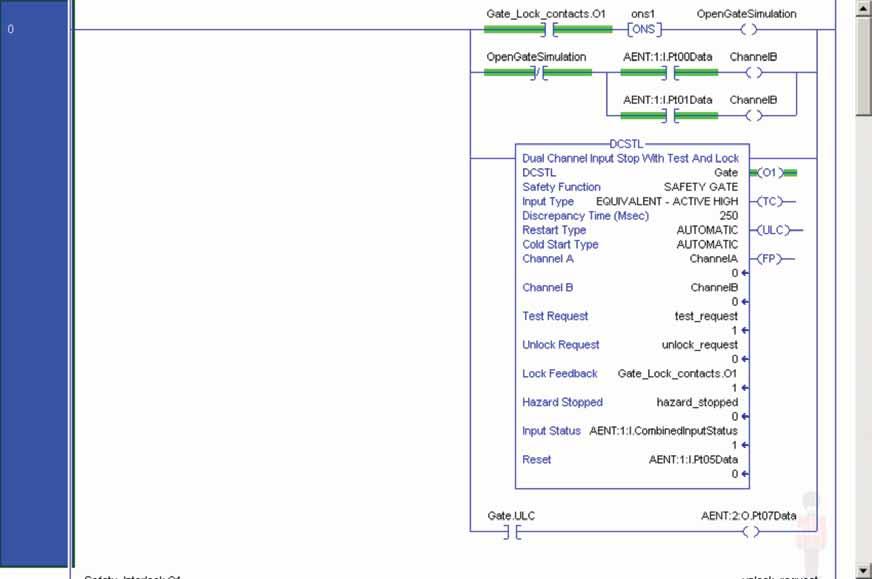
15 15 6. Click Output Configuration and configure the module as shown. The electromechanical coil on the contactor (outputs 0/1) can be pulse tested without reacting to the brief LO pulse. Output 7 is the TLS3-GD2 locking solenoid. 7. Click OK. Programming The Dual Channel Input Stop with Test and Lock (DCSTL) instruction monitors and locks dual channel safety devices whose main function is to stop a machine safely. For example, a safety gate with locking solenoid. When the unlock request goes HI, the DCSTL instruction waits for the Hazard Stopped input to go HI, and then turns on the ULC (unlock command) output. At the same time, the output (O1) goes LO to indicate that the gate is no longer protecting the hazard. The Lock Feedback should go LO, indicating the gate is indeed unlocked. The operator can now open the gate. Note that the DCSTL requires that the door monitors (Channel A and Channel B) cycle at this time or a fault occurs when restart is attempted. This cycle can be done by opening or closing the gate or can be done in software as shown later in this section. In this example, the unlock request is generated by placing a demand on the safety interlock being controlled by the DCS instruction. For your application, all that is required is that unlock request be set LO. The demand on the safety interlock drops out the safety contactors, and 5 seconds later the hazard stopped tag is set HI. This causes the DCSTL instruction to set the ULC output which energizes output 7 and unlocks the gate. Your application needs to determine the proper way to generate the hazard stopped tag. There are two (2) lock monitoring contacts on the TLS3-GD2 switch, yet there is only one (1) lock feedback tag required for the DCSTL instruction. The DCM instruction is used to monitor both lock contacts, and its output used for the DCSTL lock feedback tag. The DCSTL, DCM and DCS instructions monitor their respective dual-channel inputs for consistency (Equivalent Active High) and detect faults when the inconsistency is detected for longer than the configured Discrepancy Time (ms). The automatic restart type allows the DCSTL and DCS outputs (O1) to reset automatically after a demand. The manual action typically required for safety is provided in rung 6 to reset the safety output enable.
16 16 Input Status typically represents the channel status of the two input channels. In this example, the Combined Input Status bit goes LO if any of the 8 input channels on the 1734-IB8S module has a fault. In this example, the DCSTL, DCM and DCS reset acts as a fault reset. Even when configured for automatic restart, a reset is required to recover from a fault. The outputs (O1) of the DCSTL, DCM and DCSD instructions are used as a safety interlock in the seal-in rung to drive the output enable tag. If any of the three (3) outputs drop out, so does the output enable, and it will remain off until a manual reset action is carried out. The Configurable Redundant Output (CROUT) instruction controls and monitors redundant outputs. Essentially this instruction verifies that feedback follows the safety outputs appropriately. For the negative feedback used in this example; if the outputs are HI, the feedback should be LO and vice versa. In this example, the feedback has 500ms to change to the proper state. Since only a single feedback circuit is being used, the feedback tag is used for both Feedback 1 and 2. The two (2) output tags from the CROUT instruction are used to drive the contactor outputs on the 1734-OB8S module.
17 17 If you wish to use software to programmatically cycle Channel A and Channel B on the DCSTL, the following code is an example of how to accomplish this. Whenever the lock feedback goes LO, for one scan Channel A and Channel B are logically dropped out to satisfy the DCSTL requirements to cycle the gate. For the rest of the time, the two door monitoring contacts drive the state of Channel A and Channel B.
18 18


 and a structure of Cat 3 (minimum).")
19 19 Falling Edge Reset ISO stipulates that instruction reset functions must occur on falling edge signals. To comply with this requirement, a One Shot Falling instruction is used on the reset rung. Then the OSF instruction Output Bit tag is used as the reset bit for the Output Enable rung. Calculation of the Performance Level When configured correctly, this Door Monitoring and Locking safety function can achieve a safety rating of PLe, Cat. 4 according to EN ISO The Functional Safety Specifications of the project call for a Performance Level on PLd (minimum) and a structure of Cat 3 (minimum). A PFHd of less than 1.0 E-06 for the overall safety function is required for PLd. The individual subsystem values are shown below. The overall safety function value is shown below. The Guard Door Monitoring and Locking safety function can be modeled as shown in the following safety related block diagram.
 are quantified using the scoring process outlined in Annex F of ISO 13849-1.")
20 20 Calculations are based on 1 operation of the safety guard door per hour; therefore 8,760 operations of contactors per year. The measures against Common Cause Failure (CCF) are quantified using the scoring process outlined in Annex F of ISO For the purposes of the PL calculation, the required score of 65 needed to fulfill the CCF requirement is considered to be met. The complete CCF scoring process must be done when implementing this example.
21 21 Verification and Validation Plan Verification and Validation play an important role in the avoidance of faults throughout the safety system design and development process. ISO/EN sets the requirements for verification and validation. It calls for a documented plan to confirm all the Safety Functional Requirements have been met. Verification is an analysis of the resulting safety control system. The Performance Level (PL) of the safety control system is calculated to confirm it meets the Required Performance Level (PLr) specified. The SISTEMA software tool is typically utilized to perform the calculations and assist with satisfying the requirements of ISO Validation is a functional test of the safety control system to demonstrate that it meets the specified requirements of the safety function. The safety control system is tested to confirm all of the safety related outputs respond appropriately to their corresponding safety related inputs. The functional test should include normal operating conditions in addition to potential fault inject of failure modes. A checklist is typically used to document the validation of the safety control system. Validation of software development is a process in which similar methodologies and techniques that are used in hardware development are deployed. Faults created through poor software development process and procedure are systemic in nature rather than faults associated with hardware which are considered as random. Prior to validating the GuardLogix Safety System, it is necessary to confirm the safety system and safety application program have been designed in accordance with the GuardLogix System Safety Reference Manual (1756-RM093) and the GuardLogix Application Instruction Safety Reference Manual (1756-RM095).
22 22 GuardLogix Door Monitoring with Safety Lock Function Verification and Validation Checklist General Machinery Information Machine Name / Model Number Machine Serial Number Customer Name Test Date Tester Name(s) Schematic Drawing Number Controller Name Safety Signature ID Safety Network Number(s) RSLogix5000 Software Version Safety Control System Modules GuardLogix Modules Firmware Version GuardLogix Safety Controller 1768-L43S CompactLogix Ethernet Bridge 1768-ENBT POINT I/O Ethernet Adapter 1734-AENT POINT I/O Input Modules 1734-IB8S POINT I/O Output Modules 1734-OB8S GuardLogix Safety System Configuration and Wiring Verification Test Step Verification Pass/Fail Changes/Modifications 1 Verify the safety system has been designed in accordance with the GuardLogix System Safety Reference Manual 1756-RM093. Verify the safety application program has been designed in accordance with the GuardLogix Application 2 Instruction Safety Reference Manual 1756-RM Visually inspect the safety system network and I/O is wired as documented in the schematics Visually inspect the RSLogix 5000 program to verify that the safety system network and I/O module configuration is configured as documented. Visually inspect the RSLogix 5000 application program to verify suitable safety certified instructions are utilized. The logic is readable, understandable and testable with the aid of clear comments. All input devices are qualified by cycling their respective actuators. Monitor the status in the RSLogix 5000 Controller Tags window. All output devices are qualified by cycling their respective actuators. Monitor the status in the RSLogix 5000 Controller Tags window. Normal Operation Verification - The Safety Relay system properly responds to all normal Start, Stop, Estop, Lock and Reset Commands Test Step Verification Pass/Fail Changes/Modifications Initiate a Start Command. Both contactors should energize for a normal machine run condition. Verify proper machine status indication and RSLogix 5000 safety application program indication. Initiate a Stop Command. Both contactors should de-energize immediately for a normal machine Stop condition. After the preset time delay, verify the door unlocks. Verify proper machine status indication and RSLogix 5000 safety application program indication. While Running, attempt to open the guard door. The door should remain closed and locked. Both contactors should remain energized and closed for a normal safe condition. Verify proper machine status indication and RSLogix 5000 safety application program indication. Repeat for all guard doors. While Stopped, attempt to open the guard door. The door should be unlocked and able to be opened. Both contactors should remain de-energized and open for a normal safe condition. Verify proper machine status indication and RSLogix 5000 safety application program indication. Repeat for all guard doors. While Stopped, with the guard door open, initiate a Start Command. Both contactors should remain de-energized and open for a normal safe condition. Verify proper machine status indication and RSLogix 5000 safety application program indication. Repeat for all guard doors. Initiate Reset Command. Both contactors should remain de-energized. Verify proper machine status indication and RSLogix 5000 safety application program indication.
23 23 Abnormal Operation Verification - The GuardLogix safety system properly responds to all foreseeable faults with corresponding diagnostics. Door Monitoring and Lock Input Tests Test Step Validation Pass/Fail Changes/Modifications While Running, remove the Door Monitor Channel 1 wire from the Safety I/O. Both contactors should de-energize. Verify proper machine status indication and RSLogix 5000 safety application program indication. Verify unable to reset and restart with fault. Restore Channel 1 and repeat for Channel 2. While Running, short the Door Monitor Channel 1 of the Safety I/O to +24VDC. Both contactors should de-energize. Verify proper machine status indication and RSLogix 5000 safety application program indication. Verify unable to reset and restart with fault. Restore Channel 1 and repeat for Channel 2. While Running, short the Door Monitor Channel 1 of the Safety I/O to (-) 0VDC. Both contactors should de-energize. Verify proper machine status indication and RSLogix 5000 safety application program indication. Verify unable to reset and restart with fault. Restore Channel 1 and repeat for Channel 2. While Running, short the Door Monitor Channels 1 & 2 of the Safety I/O. Both contactors should de-energize. Verify proper machine status indication and RSLogix 5000 safety application program indication. Verify unable to reset and restart with fault. Restore Channel 1 & 2 wiring. While Running, short Channel 1 to Test Source 1 of the Safety I/O. Open the guard door. Both contactors should de-energize. Verify proper machine status indication and RSLogix 5000 safety application program indication. Verify unable to reset and restart with fault. Restore Channel 1 and repeat for Channel 2. While Running, remove the Lock Monitor Channel 1 wire from the Safety I/O. Both contactors should de-energize. Verify proper machine status indication and RSLogix 5000 safety application program indication. Verify unable to reset and restart with fault. Restore Channel 1 and repeat for Channel 2. While Running, short the Lock Monitor Channel 1 of the Safety I/O to +24VDC. Both contactors should de-energize. Verify proper machine status indication and RSLogix 5000 safety application program indication. Verify unable to reset and restart with fault. Restore Channel 1 and repeat for Channel 2. While Running, short the Lock Monitor Channel 1 of the Safety I/O to (-)0VDC. Both contactors should de-energize. Verify proper machine status indication and RSLogix 5000 safety application program indication. Verify unable to reset and restart with fault. Restore Channel 1 and repeat for Channel 2. While Running, short the Lock Monitor Channel 1 &2 of the Safety I/O. Both contactors should 9 de-energize. Verify proper machine status indication and RSLogix 5000 safety application program indication. Verify unable to reset and restart with fault. Restore Channel 1 & 2 wiring. GuardLogix Controller and Network Tests Test Step Validation Pass/Fail Changes/Modifications 1 2 While Running, remove the Ethernet network connection between the Safety I/O and the controller. All contactors should de-energize. Verify proper machine status indication and I/O Connection Status in the RSLogix 5000 safety application program. Restore the Safety I/O module network connection and allow time to reestablish communication. Verify the Connection Status Bit in the RSLogix 5000 safety application program. Repeat for all Safety I/O connections. While Running, switch the controller out of Run Mode. All contactors should de-energize. Return key 3 switch back to Run Mode, all contactors should remain de-energized. Verify proper machine status indication and RSLogix 5000 safety application program indication. Safety Contactor Output Tests Test Step Validation Pass/Fail Changes/Modifications Initiate a Start Command. Both contactors should energize for a normal machine run condition. Verify proper machine status indication and RSLogix 5000 safety application program indication. While Running, remove the contactor feedback from the Safety I/O. All contactors should remain energized. Initiate a Stop command and attempt a Reset command. The system should not Restart or Reset. Verify proper machine status indication and RSLogix 5000 safety application program indication. While Running, short the contactor feedback to the Safety I/O. All contactors should remain energized. Initiate a Stop command and attempt a Reset command. The system should not Restart or Reset. Verify proper machine status indication and RSLogix 5000 safety application program indication. While Stopped, remove the safety output to the door lock. The door should remain locked and all contactors should remain de-energized. Verify proper machine status indication and RSLogix 5000 safety application program indication.
24 24 Additional Resources For more information about the products used in this example refer to these resources. Resource Compact GuardLogix Controllers User Manual, Publication 1768-UM002 Description Provides information on configuring, operating, and maintaining Compact GuardLogix controllers. POINT Guard I/O Safety Modules Installation and User Manual, Publication 1734-UM013 GuardLogix Controller Systems Safety Reference Manual, Publication 1756-RM093 GuardLogix Safety Application Instruction Set Reference Manual, Publication 1756-RM095 Safety Accelerator Toolkit for GuardLogix Systems Quick Start Guide, Publication IASIMP-QS005 Provides information on installing, configuring, and operating POINT Guard I/O Modules. Contains detailed requirements for achieving and maintaining safety ratings with the GuardLogix controller system. Provides detailed information on the GuardLogix Safety Application Instruction Set. Provides a step-by-step guide to using the design, programming, and diagnostic tools in the Safety Accelerator Toolkit. Safety Products Catalog You can view or download publications at To order paper copies of technical documentation, contact your local Allen-Bradley distributor or Rockwell Automation sales representative. For More Information on Safety Function Capabilities, visit: discover.rockwellautomation.com/safety Rockwell Automation, Allen-Bradley, GuardLogix, RSLogix 5000, CompactLogix, Stratix 2000, and POINT Guard I/O are trademarks of Rockwell Automation, Inc. Trademarks not belonging to Rockwell Automation are property of their respective companies. Publication SAFETY-AT061B-EN-E January 2013 Supersedes Publication SAFETY-AT061A-EN-E October 2012 Copyright 2013 Rockwell Automation, Inc. All Rights Reserved.
NHP SAFETY REFERENCE GUIDE
 NHP SAFETY REFERENCE GUIDE GuardLogix SAFETY FUNCTION DOCUMENTS Emergency Stop Table of Contents: Introduction 6-121 Important User Information 6-121 Safety Function Realization 6-122 General Safety Information
GuardLogix: TLS Guardlocking Application
 Safety Application Example GuardLogix: TLS Guardlocking Application Safety Rating: PLd, Cat. 3 to EN ISO 13849.1 2008 Introduction... 2 Important User Information... 2 General Safety Information... 3 Description...
NHP SAFETY REFERENCE GUIDE
 NHP SAFETY REFERENCE GUIDE GuardLogix SAFETY FUNCTION DOCUMENTS Cable Pull Switch - Products: GuardLogix Series Connection of Cable Pull Switches Safety Rating: PLd, Cat. 3 to EN ISO 13849-1: 2008 Table
GuardLogix: Dual Zone Gate Protection with E-stop and Trojan Interlock Switch
 Safety Application Example GuardLogix: Dual Zone Gate Protection with E-stop and Trojan Interlock Switch Safety Rating: PLd, Cat. 3 to EN ISO 13849.1 2008 Introduction... 2 Important User Information...
NHP SAFETY REFERENCE GUIDE
 NHP SAFETY REFERENCE GUIDE GuardLogix SAFETY FUNCTION DOCUMENTS Light Curtain Table of Contents: Introduction 6-22 Important User Information 6-22 Safety Function Realization 6-23 General Safety Information
GuardLogix: Safety Gate Application with SensaGuard Switch
 Safety Application Example GuardLogix: Safety Gate Application with SensaGuard Switch Safety Rating: PLe, Cat. 4 to EN ISO 13849.1 2008 Introduction...2 Important User Information...2 General Safety Information...3
Safety Function: Muting Products: Light Curtain RightSight Optical Sensors GuardLogix Controller
 Safety Function: Muting Products: Light Curtain RightSight Optical Sensors GuardLogix Controller Safety Rating: PLe, Cat. 4 to EN ISO 13849.1 2008 Table of Contents Introduction 3 Important User Information
Safety Function: Safety Camera
 Safety Function: Safety Camera Products: SC300 Safety Camera, GuardLogix Controller Safety Rating: CAT. 3, PLd to EN ISO 13849-1: 2008 Application Technique 2 Safety Function: Safety Camera Important User
NHP SAFETY REFERENCE GUIDE
 NHP SAFETY REFERENCE GUIDE GuardLogix SAFETY FUNCTION DOCUMENTS Safety Mat Stop Table of Contents: Introduction 6-204 Important User Information 6-204 General Safety Information 6-205 Safety Function Realization:
NHP SAFETY REFERENCE GUIDE
 NHP SAFETY REFERENCE GUIDE GuardLogix SAFETY FUNCTION DOCUMENTS Pneumatic Safety Valves- Products: GuardLogix Controller, E-stop, Safety I/O Module, DM 2 Safety Valve Safety Rating: CAT. 3, PLd to EN ISO
NHP SAFETY REFERENCE GUIDE
 NHP SAFETY REFERENCE GUIDE GuardLogix SAFETY FUNCTION DOCUMENTS Light Curtain with Muting Table of Contents: Introduction 6-4 Important User Information 6-4 Safety Function Realization 6-42 General Safety
Application Technique. Safety Function: SensaGuard Non-contact Interlock Switch
 Application Technique Safety Function: SensaGuard Non-contact Interlock Switch Products: SensaGuard Switch, GuardLogix Controller Safety Rating: CAT. 4, PLe to EN ISO 13849-1: 2008 2 Safety Function: SensaGuard
Application Technique. Safety Function: Safety Camera with E-stop
 Application Technique Safety Function: Safety Camera with E-stop Products: Guardmaster Dual-input Safety Relay, Guardmaster SC300 Safety Camera Safety Rating: PLd, Cat. 3 to EN ISO 13849-1: 2008 2 Safety
NHP SAFETY REFERENCE GUIDE
 NHP SAFETY REFERENCE GUIDE GSR SAFETY FUNCTION DOCUMENTS E-Stop Safety Function Table of Contents: Introduction 6-18 Important User Information 6-18 General Safety Information 6-19 Safety Function Realization
Using a Guard Locking Interlock Switch and Light Curtains with DeviceNet Guard I/O and a GuardLogix Controller
 Safety Application Example Using a Guard Locking Interlock Switch and Light Curtains with DeviceNet Guard I/O and a GuardLogix Controller Safety Rating: Category 3, according to EN954-1 Introduction...
NHP SAFETY REFERENCE GUIDE
 NHP SAFETY REFERENCE GUIDE GSR SAFETY FUNCTION DOCUMENTS 2 Hand Control Safety Function 800Z Zero Force Buttons / MSR125 Safety Relay / GSR SI Safety Relay Table of Contents: Introduction 6-3 Important
PowerFlex 70 Safe-Off Control EtherNet/IP Guard I/O Safety Module and GuardLogix Integrated Safety Controller
 Safety Application Example PowerFlex 70 Safe-Off Control EtherNet/IP Guard I/O Safety Module and GuardLogix Integrated Safety Controller Safety Rating: Category 3 (also see Achieving a Cat. 4 Safety Rating)
Actuator Subsystems Stop Cat. 0 or 1 via an Integrated Safety Controller and PowerFlex 527 Drive with Hardwired Safe Torque Off Safety Function
 Application Technique Actuator Subsystems Stop Cat. 0 or 1 via an Integrated Safety Controller and PowerFlex 527 Drive with Hardwired Safe Torque Off Safety Function Products: GuardLogix 5570 or Compact
NHP SAFETY REFERENCE GUIDE
 NHP SAFETY REFERENCE GUIDE 440C SAFETY FUNCTION DOCUMENTS Emergency Stop with a Configurable Safety Relay Products: Emergency Stop, Guardmaster 440C-CR30 Configurable Safety Relay, 100S-C Safety Contactors
Using TLS3-GD2 Guardlocking Interlock with ArmorBlock Guard I/O and SmartGuard Controller
 Safety Application Example Using TLS3-GD2 Guardlocking Interlock with ArmorBlock Guard I/O and SmartGuard Controller Guardlocking with On-machine Components Safety Rating: Category 3, according to EN954-1
NHP SAFETY REFERENCE GUIDE
 NHP SAFETY REFERENCE GUIDE GSR SAFETY FUNCTION DOCUMENTS SensaGuard Non-contact Interlock Switch with E-stop Table of Contents: Important User Information 45 General Safety Information 45 Introduction
Application Technique. Safety Function: Safe Limited Speed and Safe Maximum Speed
 Application Technique Safety Function: Safe Limited Speed and Safe Maximum Speed Products: TLSZR-GD2 Guard Locking Switch/Guardmaster Safety Relay/ PowerFlex 70 Drive Safety Rating: PLd, Cat. 3 to EN ISO
L01 - Effective Design Methods for Integrating Safety Using Logix Controllers. For Classroom Use Only!
 L01 - Effective Design Methods for Integrating Safety Using Logix Controllers For Classroom Use Only! Important User Information This documentation, whether, illustrative, printed, online or electronic
GuardLogix Controller to Kinetix 6000 Drive with Safe-Off using EtherNet/IP CompactBlock Guard I/O Module
 Safety Application Example GuardLogix Controller to Kinetix 6000 Drive with Safe-Off using EtherNet/IP CompactBlock Guard I/O Module Safety Rating: SIL3/Category 3 (also see SIL3/CAT4 section), according
Using GuardShield Light Curtains (Safe 4, Micro 400, or 440L), with ArmorBlock Guard I/O and SmartGuard Controller
, with ArmorBlock Guard I/O and SmartGuard Controller") Safety Application Example Using GuardShield Light Curtains (Safe 4, Micro 400, or 440L), with ArmorBlock Guard I/O and SmartGuard Controller Light Curtain with On-machine Components Safety Rating: Category
Safety Application Example Using GuardShield Light Curtains (Safe 4, Micro 400, or 440L), with ArmorBlock Guard I/O and SmartGuard Controller Light Curtain with On-machine Components Safety Rating: Category
NHP SAFETY REFERENCE GUIDE
 NHP SAFETY REFERENCE GUIDE GSR SAFETY FUNCTION DOCUMENTS Safe Limited Speed and Safe Maximum Speed Table of Contents: General Safety Information 6-83 Introduction 6-85 Safety Function Realization: Risk
Application Technique. Products: Guardmaster 440C-CR30 Configurable Safety Relay, PowerFlex 755 Drive. Safety Rating: CAT. 3, PLe to ISO : 2008
 Application Technique Safety Function: Actuator Subsystems Stop Category 0 or Stop Category 1 via a Configurable Safety Relay and PowerFlex 755 Drive with Hardwired Safe Torque-off Products: Guardmaster
Application Technique. Products: Guardmaster 440C-CR30 Configurable Safety Relay, PowerFlex 525 AC Drive
 Application Technique Safety Function: Actuator Subsystems Stop Category 0 or Stop Category 1 via a Configurable Safety Relay and PowerFlex 525 Drive with Hardwired Safe Torque-off Products: Guardmaster
GuardLogix Controller Systems
 Safety Reference Manual GuardLogix Controller Systems Catalog Numbers 1756-L61S, 1756-L62S, 1756-L63S, 1756-L71S, 1756-L72S, 1756-L73S, 1756-L73SXT, 1756-LSP, 1756-L7SP, 1756-L7SPXT, 1768-L43S, 1768-L45S
ControlLogix SIL2 System Configuration
 ControlLogix SIL2 System Configuration Using RSLogix 5000 Subroutines Application Technique (Catalog Numbers 1756 and 1492) Important User Information 8 / 2011 Solid state equipment has operational characteristics
NHP SAFETY REFERENCE GUIDE
 NHP SAFETY REFERENCE GUIDE GSR SAFETY FUNCTION DOCUMENTS Safety Function: Actuator Subsystems Stop Category 1 via the PowerFlex 525 and PowerFlex 527 Drives with Safe Torque-off Table of Contents: Important
Safety Function: Actuator Subsystems Stop Category 1 via the PowerFlex 525 and PowerFlex 527 Drives with Safe Torque-off
 Application Technique Safety Function: Actuator Subsystems Stop Category 1 via the PowerFlex 525 and PowerFlex 527 Drives with Safe Torque-off Products: Guardmaster Dual-input Safety Relay, Guardmaster
GuardLogix Controller Systems
 Safety Reference Manual Original Instructions GuardLogix Controller Systems Catalog Numbers 1756-L61S, 1756-L62S, 1756-L63S, 1756-L71S, 1756-L72S, 1756-L73S, 1756-L73SXT, 1756-LSP, 1756-L7SP, 1756-L7SPXT,
DriveGuard. Safe-Off Option for PowerFlex 70 AC Drives. User Manual.
 DriveGuard Safe-Off Option for PowerFlex 70 AC Drives User Manual www.abpowerflex.com Important User Information Solid state equipment has operational characteristics differing from those of electromechanical
Introduction to Safety PLCs GuardLogix & CIP Safety
 Introduction to Safety PLCs GuardLogix & CIP Safety Jon Riemer Solution Architect Safety & Security Functional Safety Engineer (TÜV Rheinland) Cyber Security Specialist (TÜV Rheinland) 2018 Rockwell Automation
NHP SAFETY REFERENCE GUIDE
 NHP SAFETY REFERENCE GUIDE 440C SAFETY FUNCTION DOCUMENTS Light Curtain and Configurable Safety Relay Products: Guardmaster 440C-CR30 Configurable Safety Relay, 440L GuardShield Light Curtain, Table of
SmartGuard 600 Controllers
 SmartGuard 600 Controllers Catalog Number 1752-L24BBB Safety Reference Manual Important User Information Solid state equipment has operational characteristics differing from those of electromechanical
GuardLogix Controller Systems
 GuardLogix Controller Systems (Catalog Numbers 1756-L61S, 1756-L62S, 1756-LSP) Safety Reference Manual Important User Information Solid state equipment has operational characteristics differing from those
GuardLogix 5570 Controller Systems
 Safety Reference Manual GuardLogix 5570 Controller Systems Catalog Numbers 1756-L71S, 1756-L72S, 1756-L73S, 1756-L73SXT, 1756-L7SP, 1756-L7SPXT, 1756-L72EROMS, Studio 5000 Logix Designer Applications Original
Color-Sensing Connected Components Building Block. Quick Start
 Color-Sensing Connected Components Building Block Quick Start Important User Information Solid state equipment has operational characteristics differing from those of electromechanical equipment. Safety
Teaching Color-Sensing Connected Components Building Block. Quick Start
 Teaching Color-Sensing Connected Components Building Block Quick Start Important User Information Solid state equipment has operational characteristics differing from those of electromechanical equipment.
Using the Safety Distribution R Box
 Safety Application Example Using the Safety Distribution R Box Introduction...2 Important User Information...2 General Safety Information...3 Description...4 SensaGuard Connections...8 Tongue Interlock
POINT Guard I/O Safety Modules
 User Manual POINT Guard I/O Safety Modules Catalog Numbers 1734-IB8S, 1734-OB8S, 1734-IE4S Important User Information Solid-state equipment has operational characteristics differing from those of electromechanical
Logix5000 Controllers Produced and Consumed Tags
 Logix5 Controllers Produced and Consumed Tags Catalog Numbers 1756 ControlLogix, 1756 GuardLogix, 1768 Compact GuardLogix, 1769 CompactLogix, 1789 SoftLogix, PowerFlex with DriveLogix Programming Manual
Logix5000 Control Systems: Connect a PanelView Plus Terminal over an EtherNet/IP Network
 Quick Start Logix5000 Control Systems: Connect a PanelView Plus Terminal over an EtherNet/IP Network Catalog Numbers Logix5000 Controllers, 2711P PanelView Plus Terminals Important User Information Solid-state
PowerFlex 700H AC Drive Safe Torque Off Option
 User Manual PowerFlex 700H AC Drive Safe Torque Off Option Catalog Number 20C-DG01 Important User Information Solid-state equipment has operational characteristics differing from those of electromechanical
Digital ac/dc (24V) Input Module
 Input Module") Installation Instructions Digital ac/dc (24V) Input Module Catalog Number 1771-IND, Series C Topic Page Important User Information 2 Before You Begin 3 Power Requirements 3 Prevent Electrostatic Discharge
Installation Instructions Digital ac/dc (24V) Input Module Catalog Number 1771-IND, Series C Topic Page Important User Information 2 Before You Begin 3 Power Requirements 3 Prevent Electrostatic Discharge
SIRIUS Safety Integrated. Modular safety system 3RK3
 Functional Example CD-FE-I-048-V10-EN SIRIUS Safety Integrated Modular safety system 3RK3 Emergency Stop with monitored Start and Protective Door with automatic start according to category 4 in EN 954-1.
Point Guard I/O Safety Modules
 User Manual Original Instructions Point Guard I/O Safety Modules Catalog Numbers 1734-IB8S, 1734-OB8S, 1734-IE4S, 1734-OBV2S Important User Information Read this document and the documents listed in the
POINT Guard I/O Safety Modules
 User Manual POINT Guard I/O Safety Modules Catalog Numbers 1734-IB8S, 1734-OB8S, 1734-IE4S Important User Information Read this document and the documents listed in the additional resources section about
Kinetix 6000 Axis Module and Shunt Module
 Installation Instructions Kinetix 6000 and Shunt Module Catalog Numbers 2094-AMxx, 2094-BMxx 2094-AMxx-S, 2094-BMxx-S 2094-BSP2 Topic Page About This Publication 1 Important User Information 2 Before You
Next Generation Guardmaster Safety Relay (GSR)
") Wiring Diagram Next Generation Guardmaster Safety Relay (GSR) Bulletin 0R Quick Reference Page Safety Relay Modules Input Devices Output Devices SIL CL Category Number 6 SI E-stop PowerFlex d 0 SI MAB
Wiring Diagram Next Generation Guardmaster Safety Relay (GSR) Bulletin 0R Quick Reference Page Safety Relay Modules Input Devices Output Devices SIL CL Category Number 6 SI E-stop PowerFlex d 0 SI MAB
Integrated Safety & PowerFlex DriveGuard
 Integrated Safety & PowerFlex DriveGuard Session Agenda Introduction to GuardLogix Approx 15min Agenda Hands-on lab Approx 1.5 hrs Topics to Cover Introduction to GuardLogix Contents GuardLogix with ControlLogix
Simple Package Measurement Connected Components Building Block. Quick Start
 Simple Package Measurement Connected Components Building Block Quick Start Important User Information Solid state equipment has operational characteristics differing from those of electromechanical equipment.
Options for ABB drives. User s manual Emergency stop, stop category 0 (option +Q951) for ACS880-07/17/37 drives
 for ACS880-07/17/37 drives") Options for ABB drives User s manual Emergency stop, stop category 0 (option +Q951) for ACS880-07/17/37 drives List of related manuals Drive hardware manuals and guides ACS880-07 drives (560 to 2800 kw)
Options for ABB drives User s manual Emergency stop, stop category 0 (option +Q951) for ACS880-07/17/37 drives List of related manuals Drive hardware manuals and guides ACS880-07 drives (560 to 2800 kw)
Solar Combiner Enclosure
 Installation Instructions Solar Combiner Enclosure Catalog Numbers 1000-SB006, 1000-SB012 Topic Page Description 1 Important Safety Instructions 3 Nameplate Data 4 Planning for Installation 4 Install the
1. Summary. 2. Contacts. Safety Controls Guidelines. Table of Contents
 The provide design criteria and specifications for safety circuit in compliance with ISO 13849-1 PL d Safety of machinery, used in General Mills manufacturing facilities. Table of Contents 1. Summary 2.
Guardmaster Safety Relays. Innovative technology in a broad portfolio of safety control solutions
 R Guardmaster Safety Relays R Innovative technology in a broad portfolio of safety control solutions Guardmaster Safety Relays Allen-Bradley Guardmaster Safety Relays from Rockwell Automation check and
CompactBlock Guard I/O Modules ArmorBlock Guard I/O Modules POINT Guard I/O Modules
 Overview Overview Control and monitor your safety devices with Guard I/O. When used with Rockwell Automation safety controllers, Guard I/O communicates on EtherNet/IP or DeviceNet using CIP Safety protocol.
PCI Expansion Slot Kit for 6181P (1500P) Series D Integrated Display Computer
 Series D Integrated Display Computer") Installation Instructions PCI Expansion Slot Kit for 6181P (1500P) Series D Integrated Display Computer Catalog Number 6189V-2PCI15R Topic Page About This Publication 1 Important User Information 2 Safety
Installation Instructions PCI Expansion Slot Kit for 6181P (1500P) Series D Integrated Display Computer Catalog Number 6189V-2PCI15R Topic Page About This Publication 1 Important User Information 2 Safety
Micro800 Programmable Controllers: Getting Started with Motion Control Using a Simulated Axis
 Quick Start Micro800 Programmable Controllers: Getting Started with Motion Control Using a Simulated Axis Catalog Numbers Bulletin 2080-LC30, 2080-LC50 Important User Information Solid-state equipment
Agenda. Session Agenda. Introduction to GuardLogix Approx 15min. Hands-on lab Approx 1.5 hrs
 Integrated Safety Session Agenda Introduction to GuardLogix Approx 15min Agenda Hands-on lab Approx 1.5 hrs Topics to Cover Introduction to GuardLogix Contents GuardLogix with ControlLogix Functionality
Allen-Bradley. User Manual. PLC-5 Backup Communication Module (1785-BCM, 1785-BEM) product icon
 product icon") Allen-Bradley PLC-5 Backup Communication Module User Manual (1785-BCM, 1785-BEM) product icon Important User Information Because of the variety of uses for this product and because of the differences between
Allen-Bradley PLC-5 Backup Communication Module User Manual (1785-BCM, 1785-BEM) product icon Important User Information Because of the variety of uses for this product and because of the differences between
Logix5000 Controllers Nonvolatile Memory Card
 Programming Manual Logix5000 Controllers Nonvolatile Memory Card 1756 ControlLogix, 1756 GuardLogix, 1769 CompactLogix, 1769 Compact GuardLogix, 1789 SoftLogix, 5069 CompactLogix, Studio 5000 Logix Emulate
1. Introduction. 2. Design. Safety and Emergency Stop Circuit Design Standard. Safety and Emergency Stop Circuit Design Standard.
 Safety and Emergency Stop Circuit Design Standard The Safety and Emergency Stop Circuit Design Standard provide design criteria and specifications for safety and emergency stop circuits used in General
The Guardmaster 440C-CR30 Software Configurable Safety Relay Training Demo Lab. For Classroom Use Only!
 The Guardmaster 440C-CR30 Software Configurable Safety Relay Training Demo Lab For Classroom Use Only! Important User Information This documentation, whether, illustrative, printed, online or electronic
Installation Instructions
 Installation Instructions Cat. No. 1771 P3, P4, P5 and P5E Use this document as a guide when installing the catalog number 1771-P3, -P4, -P5 or -P5E power supplies. Because of the variety of uses for the
CompactLogix Power Supplies Specifications
 Technical Data CompactLogix Power Supplies Specifications 1768 CompactLogix Power Supplies Catalog Numbers 1768-PA3, 1768-PB3 1769 Compact I/O Power Supplies Catalog Numbers 1769-PA2, 1769-PB2, 1769-PA4,
PowerMonitor 5000 Unit Catalog Number Upgrade
 Installation Instructions PowerMonitor 5000 Unit Catalog Number Upgrade Catalog Numbers 1426-MxE-xxx Topic Page Upgrade the Device Catalog Number with the ControlFLASH Utility 3 Determine Communication
Options for ABB drives. User s manual Emergency stop, stop category 1 (option +Q964) for ACS880-07/17/37 drives
 for ACS880-07/17/37 drives") Options for ABB drives User s manual Emergency stop, stop category 1 (option +Q964) for ACS880-07/17/37 drives List of related manuals Drive hardware manuals and guides ACS880-07 drives (560 to 2800 kw)
Options for ABB drives User s manual Emergency stop, stop category 1 (option +Q964) for ACS880-07/17/37 drives List of related manuals Drive hardware manuals and guides ACS880-07 drives (560 to 2800 kw)
CENTERLINE 2100 Motor Control Centers EtherNet/IP Network Adapter
 User Manual CENTERLINE 2100 Motor Control Centers EtherNet/IP Network Adapter Catalog Numbers 2100-ENET Series A FRN 1.XXX Important User Information Solid-state equipment has operational characteristics
Adapter Kit for PanelView 1200/1200e Touch Screen Terminal Cutout
 Installation Instructions Adapter Kit for PanelView 1200/1200e Touch Screen Terminal Cutout Catalog Numbers 2711-NR5T, 2711P-RAT12E2 Topic Page About This Publication 1 Important User Information 2 About
Bidirectional (4-sensor, T-type) Muting With MSR42 Relay Connected Components Building Block
 Muting With MSR42 Relay Connected Components Building Block") Bidirectional (4-sensor, T-type) Muting With MSR42 Relay Connected Components Building Block Catalog Numbers MSR42, MicroLogix 1100, GuardShield Micro 400 Light Curtains Quick Start Important User Information
Bidirectional (4-sensor, T-type) Muting With MSR42 Relay Connected Components Building Block Catalog Numbers MSR42, MicroLogix 1100, GuardShield Micro 400 Light Curtains Quick Start Important User Information
InView Firmware Update
 Installation Instructions InView Firmware Update Topic Page Hazardous Voltage 3 Change EPROM on 2706-P72, 2706-P74 Display 3 Change EPROM on 2706-P42, 2706-P44 Displays 5 Firmware Upgrade Kit 7 2 InView
Bidirectional (2-sensor, T-type) Muting With Enable Using MSR42 Relay Connected Components Building Block
 Muting With Enable Using MSR42 Relay Connected Components Building Block") Bidirectional (2-sensor, T-type) Muting With Enable Using MSR42 Relay Connected Components Building Block Catalog Numbers MSR42, MicroLogix 1100, GuardShield Micro 400 Light Curtains Quick Start Important
Bidirectional (2-sensor, T-type) Muting With Enable Using MSR42 Relay Connected Components Building Block Catalog Numbers MSR42, MicroLogix 1100, GuardShield Micro 400 Light Curtains Quick Start Important
Catalog Numbers 9308-RSFB64ENE, 9308-RSFB256ENE, 9308-RSFB1024ENE
 Release Notes RSFieldbus Software Catalog Numbers 9308-RSFB64ENE, 9308-RSFB256ENE, 9308-RSFB1024ENE Topic Page Important User Information 2 Before You Begin 3 Software Requirements 4 Install the Software
Kinetix 300 Memory Module Programmer
 Kinetix 300 Memory Module Programmer Catalog Number 2097-PGMR Topic About the Memory Module Programmer 1 Parts List 3 Batteries Operation 4 Using Memory Module Programmer 6 Switch On/Off Memory Module
Application Guide. Considerations for 32 Bit Integer Parameters in 16 Bit Processors. PowerFlex 700VC, PowerFlex 700S. Introduction.
 Topic: Drive Product: Introduction User Information Considerations for 32 Bit Integer Parameters in 16 Bit Processors PowerFlex 700VC, PowerFlex 700S An Application Guide provides generic information on
Guard I/O EtherNet/IP Safety Modules
 User Manual Guard I/O EtherNet/IP Safety Modules Catalog Numbers 1791ES-IB8XOBV4, 1791ES-IB16, 1732ES-IB12XOB4, 1732ES-IB12XOBV2 Important User Information Read this document and the documents listed in
Simple Motion Control Connected Components Building Block. Quick Start
 Simple Motion Control Connected Components Building Block Quick Start Important User Information Solid state equipment has operational characteristics differing from those of electromechanical equipment.
Logix5000 Controllers Function Block Diagram
 Logix5000 Controllers Function Block Diagram Catalog Numbers 1756 ControlLogix, 1769 CompactLogix, 1789 SoftLogix, 1794 FlexLogix, PowerFlex 700S with DriveLogix Programming Manual Important User Information
ProcessLogix R510.0 Server Installation Instructions
 ProcessLogix R510.0 Server Installation Instructions Installation Instructions Before you begin... This publication guides you through the remaining processes required to initialize a ProcessLogix Server.
ControlLogix Configurable Flowmeter Module
 User Manual ControlLogix Configurable Flowmeter Module Catalog Numbers 1756-CFM Important User Information Solid-state equipment has operational characteristics differing from those of electromechanical
FLEX 5000 Digital I/O Modules
 User Manual Original Instructions FLEX 5000 Digital I/O Modules Catalog Numbers 5094-IB16, 5094-IB16XT, 5094-OB16, 5094-OB16XT, 5094-OW8I, 5094-OW8IXT Important User Information Read this document and
Logix5000 Control Systems: Connect POINT I/O Modules over a DeviceNet Network
 Quick Start Logix5000 Control Systems: Connect POINT I/O Modules over a DeviceNet Network Catalog Numbers Logix5000 Controllers, 1734 POINT I/O Modules Important User Information Solid-state equipment
Logix5000 Controllers Produced and Consumed Tags
 Programming Manual Logix5 Controllers Produced and Consumed Tags Catalog Numbers 1756 ControlLogix, 1756 GuardLogix, 1768 Compact GuardLogix, 1769 CompactLogix, 1789 SoftLogix, PowerFlex with DriveLogix
Safety-related controls SIRIUS Safety Integrated
 Functional Example CD-FE-I-018-V30-EN Safety-related controls SIRIUS Safety Integrated with monitored start up to SIL 1 acc. to IEC 62061 and PL c acc. to ISO 13849-1 with a SIRIUS safety relay 3TK28 with
Import/Export Project Components. Programming Manual
 Import/Export Project Components Programming Manual Important User Information Solid state equipment has operational characteristics differing from those of electromechanical equipment. Safety Guidelines
Kinetix 5700 Safe Monitor Functions
 Safety Reference Manual Original Instructions Kinetix 5700 Safe Monitor Functions Catalog Numbers 2198-D006-ERS3, 2198-D012-ERS3, 2198-D020-ERS3, 2198-D032-ERS3, 2198-D057-ERS3 2198-S086-ERS3, 2198-S130-ERS3,
DeviceNet Network Configuration
 User Manual DeviceNet Network Configuration 1756 ControlLogix, 1756 GuardLogix, 1769 CompactLogix, 1769 Compact GuardLogix, 1789 SoftLogix, Studio 5000 Logix Emulate Important User Information Solid-state
Options for ABB drives. User s manual Prevention of unexpected start-up (option +Q957) for ACS880-07/17/37 drives
 for ACS880-07/17/37 drives") Options for ABB drives User s manual Prevention of unexpected start-up (option +Q957) for ACS880-07/17/37 drives List of related manuals Drive hardware manuals and guides ACS880-07 drives (560 to 2800
Options for ABB drives User s manual Prevention of unexpected start-up (option +Q957) for ACS880-07/17/37 drives List of related manuals Drive hardware manuals and guides ACS880-07 drives (560 to 2800
Installation Instructions
 Installation Instructions (Cat. No. 1771-OBN Series B) Use this document as a guide when installing the catalog number 1771-OBN series B output module. Because of the variety of uses for the products described
Siemens Safety Integrated Take a safe step into the future
 Engineered with TIA Portal Machine Safety Life-Cycle Siemens Safety Integrated Take a safe step into the future Unrestricted / Siemens Industry Inc. 2015. All Rights Reserved. www.usa.siemens.com/safety
ISO INTERNATIONAL STANDARD. Safety of machinery Safety-related parts of control systems Part 1: General principles for design
 INTERNATIONAL STANDARD ISO 13849-1 Second edition 2006-11-01 Safety of machinery Safety-related parts of control systems Part 1: General principles for design Sécurité des machines Parties des systèmes
FLEX I/O Dual Port EtherNet/IP Adapter Modules
 User Manual FLEX I/O Dual Port EtherNet/IP Adapter Modules Catalog Numbers 1794-AENTR, 1794-AENTRXT Important User Information Solid-state equipment has operational characteristics differing from those
InView Communication Modules
 Installation Instructions InView Communication Modules Catalog Numbers 2706-PxM, 2706-PxK, 2706-PxP Topic Page About This Publication 1 Important User Information 2 Power Supply Requirements 3 Mount the
Allen-Bradley Motors
 Installation Instructions Firmware Update Instructions for Ethernet, Enhanced and ControlNet PLC-5 Programmable Controllers Purpose Firmware Update Kit Contents Hardware and Software Requirements This
Differential Liquid/Gas Pressure Transmitter
 Installation Instruction Differential Liquid/Gas Pressure Transmitter Catalog Number(s) 1414-CPZ10FWFAA, 1414-IPZ10FWFAA Explosion Hazard WARNING Do not use in an explosive or hazardous environment, with
DeviceNet CLX PA75 CLX A4. GuardLogix L62S. GuardLogix SafetyPartner LSP. DeviceNet Scanner DNB
 GuardLogix CLX- - 1756-PA75 CLX- - 1756-A4 GuardLogix -1756-L62S GuardLogix SafetyPartner - 1756-LSP DeviceNet Scanner - 1756-DNB Ethernet -1756-ENBT Point I/O DeviceNet 1734-ADN Point I/O 8 pt 1734-IB8
New developments about PL and SIL. Present harmonised versions, background and changes.
 Safety evevt 2017 Functional safety New developments about PL and SIL. Present harmonised versions, background and changes. siemens.com ISO/ TC 199 and IEC/ TC 44 joint working group 1 - Merging project