4900 SERIES PLC INTERLOCK SYSTEM
|
|
|
- Eugenia Ryan
- 6 years ago
- Views:
Transcription

")


 or Interlocks involving multiple rooms and up to FIG.")

1 4900 SERIES PLC INTERLOCK SYSTEM The 4900 series PLC interlock controller is a cost effective method for operating door interlock and mantrap systems of up to 120 doors. The basic system consists of a controller and one or more I/O (Input Output) modules. The I-O Modules are available as a 4X4 or an 8X8 configuration depending on the number of inputs and outputs required. Outputs are a combination of DPDT relays and open collector powered auxiliary outputs able to drive low voltage loads directly, up to 40 ma per channel. The 4900 controller is pre-programmed for most applications and shipped from stock. It can be programmed at the factory for custom application requiring timed sequences (such as airlock, wash down etc.) or Interlocks involving multiple rooms and up to 120 doors. FIG. 1 A Inter-board Connectors G Power Connector VDC M Signal (Dry Contact) Input Terminals B I-O Address Jumper Matrix H Module Power In Factory Wired N Output Relay Status Indicating LED C Watch Dog blink rate 3 times/sec I Power Out Terminals O Relay Contact Terminals D Programming Port J Output Relays switch 3 Amp Max P Powered Output Terminals E Power Indicating LED K Input Status Indicating LEDs F Memory Backup Coin Cell L Output Fuse In series with Com Page 1 of 10 rev. 4/23/15 DORTRONICS SYSTEMS. INC
 has 8 input channels and 8 outputs comprised of 4 independent DPDT relay contact sets (one of each is fused) and 4 powered outputs (40 ma max.")
 will cause the power supply fire alarm relay to de-energize cutting low voltage power to all door locks")

. Inputs require dry contact only.")
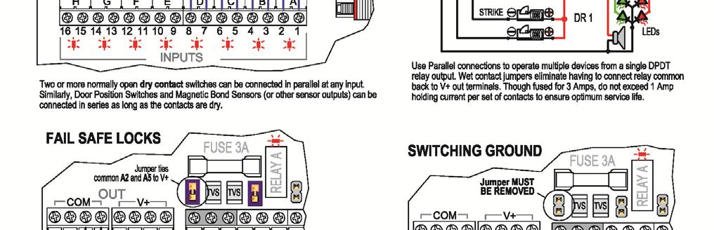
2 HOOKUP 4900 MANUAL The standard 4900 controller comes mounted in a lockable NEMA enclosure with one or more Input/Output (I/O) relay modules and a 4 Amp power supply with user selectable output of 12 or 24 VDC. The 4X4 I/O module (see Figure 2) has 8 input channels and 8 outputs comprised of 4 independent DPDT relay contact sets (one of each is fused) and 4 powered outputs (40 ma max. per channel) that may be used to drive indicators, and/or auxiliary relays. The power supply has a Fire Alarm Interface. An interruption of a normally closed fire alarm circuit (such as the activation of a pull box) will cause the power supply fire alarm relay to de-energize cutting low voltage power to all door locks and other devices connected to the switched power terminals. Devices connected to the unswitched power terminals remain powered. FIG. 2 TYPICAL INSTALLATION DOOR POSITION SWITCH Door switch contacts must be closed when the door is closed corresponding Input LED lights to indicate closed contacts at the input. Twisted pair wiring AWG gauge 22 or larger is recommended for all signal inputs. REQUEST FOR ACCESS DEVICES Unless otherwise specified, controller follows access control device unlock time (typically a card reader). Inputs require dry contact only. Use an isolation relay for non-dry contact connections (such as an output from an intercom). AWG gauge 22 twisted pair or larger is recommended. Use sufficient wire diameter to minimize voltage drop for long wire runs. Use shielded wire in proximity to sources of interference such as large motors, network servers, and sources of electromagnetic radiation. Page 2 of 10 rev. 4/23/15 DORTRONICS SYSTEMS. INC
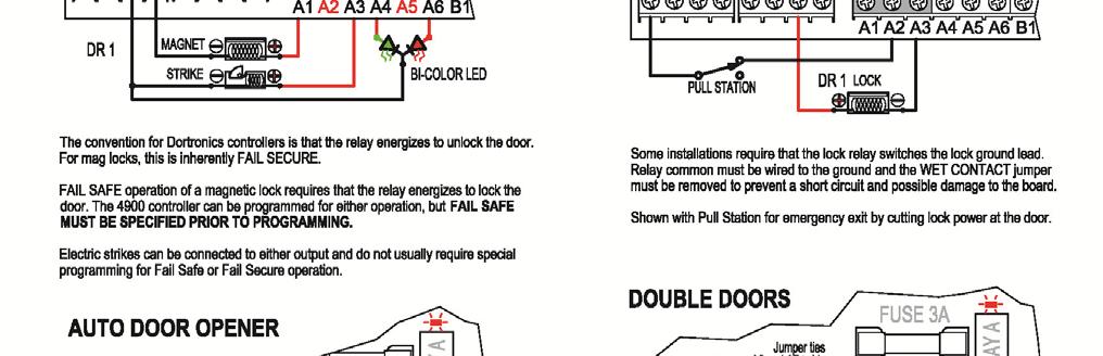
3 DOOR LOCKS Mag locks and strikes are connected to the designated relay contacts by labeled screw terminals. Relay outputs are dry contacts. Power for maglocks, strikes and indicators may be external or sourced from the I-O Module. See Figure 1 (I). Jumpers may be used to connect relay common to supply positive (+). When relays are operated with wet contacts shorting the output will blow the fuse and may damage the I-O board! NOTE: Use a wire of sufficient diameter and rating to minimize voltage drop, especially over long wire runs. AWG 18 gauge is recommended for power circuits. TRAFFIC AND LOCK STATUS LIGHTS LED and incandescent indicator lights, typically red to show a locked or inaccessible condition and green to show an unlocked or freely accessible condition, may be connected as shown in Figure 2. AWG 22 gauge or larger is recommended for signaling and low-power indicator circuits. DOOR ALARM A relay output is provided on most, but not all, 4900 interlock systems, to indicate an interlock violation. Refer to the hookup drawing supplied with the mantrap as built. The Door Alarm signals when a door has been opened without a valid request for access, or in the case of normally unlocked systems, when 2 doors are open simultaneously. Wiring should be sized according to the signaling load. PANIC EGRESS OPTION Most 4900 interlock systems have an emergency egress function. This is in addition to the Fire Alarm Relay. The Panic release unlocks all doors regardless of door status for immediate egress in case of a door position switch failure, a stuck door, an environmental emergency or any other reason that requires immediate egress. To enable the emergency egress, install a maintained contact normally open switch at the terminals shown on the drawing for the system being installed. When actuated, the doors will unlock for as long as the switch contacts remain closed. The Door Alarm Relay (on all 2 & 3 door systems) will be energized to alert others to the unsecured condition. Building codes vary by location. The installer is responsible for understanding and working in compliance with all local codes and regulations as defined by the local governing authority. INTER-BOARD CONNECTORS (A) Up to sixteen 4X4 modules and eight 8X8 modules can be connected to a single controller. ADDRESS JUMPER MATRIX (B) Each I-O Module connected to the controller must have a unique address. Jumpers are used to select a binary code representing the address of each I-O Module. WATCHDOG LED (C) The PLC status is continually monitored by a watchdog function. The watchdog LED (see Fig 1) blinks rapidly (at a rate of 3 times per second) to indicate that a program is loaded and is being executed correctly. If the watchdog indicator is not blinking, verify that there is 12 or 24 VDC at the correct power terminals. If power is present and the watchdog indicator is not blinking, or blinking slowly, contact Dortronics for technical assistance. POWER OUT TERMINALS (I) For convenience, each I-O module has four positive and four negative terminals to distribute power supply voltage to the locks and other powered devices. Complex hookups may require an additional external terminal strip to accommodate all of the necessary connections. Page 3 of 10 rev. 4/23/15 DORTRONICS SYSTEMS. INC
4 RELAY OUTPUTS (J) The output relays have contacts rated for 2 Amp holding current at 30 VDC. When connected to inductive loads (including almost all electric strikes and magnetic locks) a protection diode or TVS (Transient Voltage Suppressor) is required (already included on 4x4 output boards). Kickback from a coil can cause arcing and damage to the contacts if not protected. Dortronics locks have an integral TVS. If a single relay is used to switch power to a pair of locks, connect the 2 nd lock to the second set of contacts to distribute the load. INPUT STATUS INDICATORS (K) When an input is grounded (closed dry contacts) the input is active. This is indicated by a lighted LED. The inputs for the 4900 series I-O modules are opto-isolated for protection against most kinds of interference. For Door Position Switches, Magnetic Bond Sensors and similar devices used to signal door status, the Normally Open contacts should be connected so that when the door is closed the contacts are closed. For easy trouble shooting, when a door is closed the input LED for the door will be lighted. When the door opens, the LED should turn off. For other REX devices such as Bio-sensors, card readers, motion detectors, pushbuttons, pneumatic switches and the like, the input LED should be on when the REX is active. NOTE: The 4X4 module has a pair of terminals for each input. The odd numbered terminal is common (ground). The 8X8 module has only four common terminals grouped together. In either case, when the input circuit is completed to ground, the input is on. FUSED OUTPUT CONTACTS (L) One set of contacts on each output relay (DPDT) is fused. The 4X4 I-O module has four user replaceable BUS type fuses (3 Amp quick blow). Never replace a blown fuse with one with a higher rating. The 8X8 I-O Module has eight resettable Polyfuses. These open the circuit when the current flow exceeds a threshold and they automatically begin to conduct again when the over-current is corrected. These are not user replaceable. Each DPDT output has a fused set of contacts. The other set are not fused. OUTPUT RELAY STATUS INDICATOR LED (N) When an output relay is energized, the LED indicator for that relay is on. Magnetic Locks are normally connected to the Normally Closed relay contacts and electric strikes are connected to the normally open contacts so that in either case, when the relay is energized the door is unlocked. For verifying correct operation, compare lighted inputs to the lighted relay indicators. A common wiring error is to fail to match the input to the correct relay output. Note that the numbering for inputs and outputs begin with zero (digital convention). This can lead to confusion as door 1is often controlled by relay 0. RELAY CONTACT TERMINAL STRIP (O) The 4X4 I-O Module provides a terminal for each relay contact and common. The 8X8 I-O Module provides a terminal for each primary (fused) contact and common, but uses a jumper to select the desired operation of the auxiliary non-fused set of relay contacts, either normally open or normally closed. If no jumper is present the auxiliary contacts are disabled. For double doors and doors using both a strike and a magnetic lock, use a separate set of relay contacts for each lock. PROGRAMMABLE POWERED OUTPUTS (P) Programmable powered auxiliary outputs are provided. When programmed, these may be used to power lights, beepers or off-board relay coils. Check with the specifications for a particular installation to see if the powered outputs have been enabled. Page 4 of 10 rev. 4/23/15 DORTRONICS SYSTEMS. INC


 have a shared")

5 AUXILIARY RELAY PACK OPTION - 4X4 I-O Module Only The 4X4 I-O Module can be expanded to 8 relay outputs using the auxiliary relay pack option. The output function of each auxiliary relay is selectable by jumper for either Normally Open or Normally Closed action. If no jumper is installed the output is disabled. Auxiliary relay pack is available for 12 or 24 Volt applications. Specify Voltage on Purchase Order NOTE: Aux Relay output contacts (DPDT) have a shared common. Do not mix voltage sources on a single Aux Relay contact set. Aux Relay coils are powered by the programmable open collector outputs. When the output is powered, an indicator LED lights and the aux relay is energized. Page 5 of 10 rev. 4/23/15 DORTRONICS SYSTEMS. INC

6 DISPLAY MODULE OPTION Some applications require the ability to adjust program variables on-site. The optional Display Module features a four digit, seven segment display and 5 programmable pushbuttons. The stacking design of the Controller with Display Module has the same footprint as a standard Controller. ANALOG INPUT (A) Two programmable analog adjustment wheels are available. When programmed, the system allows for essentially endlessly variable adjustments for one or two values such as two different time delays. SEVEN SEGMENT, FOUR CHARACTER DISPLAY (B) A programmable four character display is available for user feedback. It can be programmed to show changes in user adjusted variables, the status of count down or count up timers, or which setting is currently operable. PROGRAMMABLE STATUS LEDs (C) There are five programmable status lights. These are typically used to alert the user that a programming step has been completed or that a programming pushbutton is active. PROGRAMMABLE PUSHBUTTONS (D) There are five programmable pushbuttons that may be used to enter changes to variable, store variables in memory, recall stored values, increase or decrease the value of stored values, set delay times and reset or clear pending actions. SUGGESTED APPLICATIONS The ability to adjust variables on site makes it possible to easily: Sequence multi-stage functions such as airlock equalization followed by deflation of door seals; Set and adjust timing variables such as unlock time, grace time before alarm sounds, timed system reset; Save event count to memory, retrieve count from memory and clear memory; Change to one or more alternate Interlock Patterns, or other logic functions; Event triggered camera on time. Page 6 of 10 rev. 4/23/15 DORTRONICS SYSTEMS. INC


7 Page 7 of 10 rev. 4/23/15 DORTRONICS SYSTEMS. INC
8 RECOMMENDED EQUIPMENT DORTRONICS PART# DESCRIPTION Dortronics #1110xDxB 1200 lb electromagnetic 12/24 VDC maglocks with built-in door position switch. Dortronics #7201xL2-H High intensity Red / Green LEDs on single gang S/S wall plate. Dortronics #7202xL2-HxCS High intensity Red / Green LEDs with Piezo sounder on double gang S/S wall plate. (Optional for use with security breach alarm output.) Dortronics #5216 PP23PPXE2 Panic mushroom switch latching push, pull. OPTIONS (AVAILABLE AT EXTRA COST) Lock Status Indicators Use Dortronics #7201xL2-H at either side of each controlled door. LEDs follow lock status (Red when secure & Green when unlocked for access). LED indicators can share low voltage (12 or 24 VDC) lock power & control relays. Door Prop Alarm Use Dortronics #7281-EA Local Door Alarm or #7286-PT5 Door Prop Alarm. Security Breach Alarm Contact factory for additional relay outputs to operate Dortronics sounder. Use Dortronics #7201xCS Piezo Sounder on single gang S/S wall plate (or add xcs option to LED Indicators). Custom Functions Contact factory for special customer specified operations. Additional charges for engineering may apply. Fused power distribution board. Dortronics # xfo Auxiliary Relay Pack 4900-RLY SPECIFICATIONS Qty Description Remarks Power In 12 or 24VDC regulated - plus, common and earth ground 3 - Screw Terminals Inputs 8 or 16 Single or Dual I-O Module dry contact only Screw Terminals Outputs 4 or 8 Single or Dual I-O Module - DPDT Relays rated 30 VDC Screw Terminals 4 or 8 Single or Dual I-O module open collector powered outputs Screw Terminals Temperature Operating 0-60 C Current See table below. Current Draw Condition Current in ma Volts Controller only with 1 I/O board quiet With 1 I/O board all driven (Relay Aux Board) With 2 (or dual) I/O boards quiet < With 2 (or dual) I/O boards + Aux relay board all driven < Controller only with 1 I/O board quiet With 1 I/O board all driven (Relay Aux Board) With 2 (or dual) I/O boards quiet < With 2(or dual) I/O boards all driven (relay aux boards) < Page 8 of 10 rev. 4/23/15 DORTRONICS SYSTEMS. INC
9 SALES - WARRANTIES Contact (Sales): Mike Palermo Sales/Customer Service Stuart Arthur Sales/Applications Specialist Bryan Sanderford National Sales Manager Contact (Technical): Joe Hanna Engineer/Applications Specialist Kevin King Engineering Support Contact (Credit): Teri Harboy Accounting; New Customer Accounts Product Warranties: All electromagnetic locks have a LIFETIME GUARANTEE against defects in material and workmanship. Defective units will be replaced or repaired based upon incoming evaluation and inspection. All other Dortronics components of the Electric Locking System shall be similarly warranted for a period of one year. Expressed warranties are conditionally based on the requirement that the items covered within the guarantee are used and maintained in accordance with the manufacturer's recommendations. A Return Authorization Number must be obtained and accompany all returns within 14 days of issue. Unused items returned for credit must be complete and packed in original unit box and are subject to a 15% restocking fee. Any shipping or order discrepancies must be reported within 5 days of receipt. Page 9 of 10 rev. 4/23/15 DORTRONICS SYSTEMS. INC
10 INSTALLATION AND OPERATION NOTES Page 10 of 10 rev. 4/23/15 DORTRONICS SYSTEMS. INC
2000 Series e/em Style Keypad Installation and Programming Manual
 2000 Series e/em Style Keypad Installation and Programming Manual Document Number: 6054022 Revision: 0 Date: 12/21/06 Table of Contents Table of Contents Section 1: Introduction... 6 1 Product Description...6
IEI emerge MicroNode Install and Setup Guide. Contents
 IEI emerge MicroNode Install and Setup Guide Contents Connecting power and the network to the MicroNode... 2 Using Power over Ethernet (PoE)... 3 or... 3 Using a 12 VDC power supply... 3 Connecting and
KP2000E/EM Series Style Keypad
 23852973 KP2000E/EM Series Style Keypad Installation and Programming Instructions Models KP2000EXX and KP2000EMXX Specifications Parameter Voltage Requirements Keypad Current Requirements (Max) Relay Contact
INSTALLATION INSTRUCTIONS 921P EntryCheck TM
 80 Avenida Acaso, Camarillo, Ca. 90 (805) 494-06 www.sdcsecurity.com E-mail: service@sdcsecurity.com INSTALLATION INSTRUCTIONS 9P EntryCheck TM The EntryCheck 9P Indoor/Outdoor Keypad is a surface mount
900-4RL Option Board. Refer to installation instructions for compatible supply models - PS902, PS904, PS906, and PS914. Note
 *44487080* 44487080 DANGER To avoid risk of electric shock, turn off AC power to power supply before installing or wiring option board. 900- Option Board Installation Instructions 900- Specifications Inputs
212iL Rev. 1.1
 212iL 1 International Electronics, Inc. 427 Turnpike Street Canton, Massachusetts 02021 212iL (illuminated Luxury) Keypad Single Unit Keypad- Control Installation Manual Features: 120 User Capability Illuminated
Quick Start Guide. SEB-710 I/O Expansion board. Introduction
 SEB-710 I/O Expansion board Revision 1.0 - (March, 2011) Saflec Systems (Pty) Ltd Quick Start Guide Introduction The SEB-710 is an I/O expansion device for additional inputs and outputs. It has eight relay
THE BRIDGE. Make any Wiegand device wireless with the Sure-fi Bridge FEATURES. Technology
 THE BRIDGE Make any Wiegand device wireless with the Surefi Bridge *Housing options sold separately. Keep your Wiegand system connected. Fix faulty Wiegand systems quickly and easily with our wireless
Power Hub Cat. No. 83A00-1. Installation Manual WEB VERSION
 Power Hub Cat. No. 83A00-1 Installation Manual WARNINGS AND CAUTIONS Read and understand all instructions. Follow all warnings and instructions marked on the product. Do not use this product near water
AirTest Model CN9000 Series Sensor Controller
 AirTest Model CN9000 Series Sensor Controller AirTest Model CN9000 Series Sensor Controller THEORY OF OPERATION A basic CN9000 configuration consists of Input/Process/Display combination modules, a 3 relay
6222 Two Door Module Technical Operations Manual
 6222 Two Door Module Technical Operations Manual TABLE OF CONTENTS Specifications...3 Overview...4 Operations...5 Custom Access Mode...5 Standard Access Mode...5 Offline Access Mode...5 Offline Memory...5
REX F-0-9 Standalone or Access Controller
 REX F-0-9 Standalone or Access Controller Power supply The controller need s external power supply to operate. The Spider W40 power supply is sufficient to power two controllers and two 12V electric strikes
MYRIAD QLC 4-CHANNEL MONITOR/CONTROLLER INSTRUCTION MANUAL
 MYRIAD QLC 4-CHANNEL MONITOR/CONTROLLER INSTRUCTION MANUAL VISIT OUR WEBSITE SIGMACONTROLS.COM MYR QLC MANUAL 013114 2 TABLE OF CONTENTS INTRODUCTION 3 Ordering Information Specifications Features WIRING
INSTALLATION INSTRUCTIONS 920P EntryCheck TM
 801 Avenida Acaso, Camarillo, Ca. 93012 (805) 494-0622 www.sdcsecurity.com E-mail: service@sdcsecurity.com INSTALLATION INSTRUCTIONS 920P EntryCheck TM The EntryCheck 920P Indoor/Outdoor Keypad is a surface-mount
232iLM Keypad Installation and Programming Instructions
 232iLM Keypad Installation and Programming Instructions Note: This product is designed to be installed and serviced by security and lock industry professionals. Specifications Case Dimensions: 6 1 / 2
MR52 READER INTERFACE
 IN IN2 IN3 IN4 INPUTS IN5 IN6 IN7 IN8 C www.mercury-security.com 2355 MIRA MAR AVE. LONG BEACH, CA 9085-755, (562)986-905 FAX (562) 986-9205 MR52 READER INTERFACE Installation and Specifications: This
MODEL SW6000 & SM6100 CENELEC INSTRUCTIONS
 MODEL SW6000 & SM6100 CENELEC INSTRUCTIONS Installation Manual 1180 METRIX Experience Value 8824 Fallbrook Dr. Houston, TX 77064, USA Tel: 1-281-940-1802 After Hours Technical Assistance: 1-713-702-8805
1 Description. 2 Specifications. Product Installation Document. Honeywell 12 Clintonville Road Northford, CT
 Honeywell 12 Clintonville Road Northford, CT 06472 http://www.honeywellpower.com HP600ULACM4CB HP600ULACM8CB Access Control Power Supply/Charger with Power Distribution Controller PN 52395:A 1/05/06 ECN
MR51e Reader Interface
 J4 J TB6 TB5 TB4 TB3 VIN VO TB2 TB J7 2.75 [69.85] 0.2 [5.08] 2.35 [59.69] J3 MR5e Reader Interface Installation and Specifications. General: www.mercury-security.com 2355 MIRA MAR AVE. LONG BEACH, CA
AK-21. Digital Keyless Entry System. Installation and Programming Instructions
 AK-2 Digital Keyless Entry System Installation and Programming Instructions (760) 8-7000 USA & Canada (800) 2-587 & (800) 92-02 Toll Free FAX (800) 68-0 www.linearcorp.com CONTENTS COMPONENT LOCATIONS.......................................
9212i INSTALLATION. Stand-Alone Keypad. Instructions
 INSTALLATION 9212i Stand-Alone Keypad Instructions Features: 4 Independent Outputs 4 Independent Timers All Outputs Assignable by Code On board 5 Amp Form C Relay 120 Users Remote Triggering Input Keypad
Digital Lighting Systems, Inc. PD216. Two Channel Dimmer and Switch Packs PROTOCOL USER'S MANUAL. PD216-UM Rev. E - 02/03
 Digital Lighting Systems, Inc. PD26 Two Channel Dimmer and Switch Packs PROTOCOL PD26 S2 S USER'S MANUAL PD26-UM Rev. E - 02/03 Digital Lighting Systems PD26 User's Manual - Page GENERAL DESCRIPTION The
Wiring Inside the card reader you will see a circuit board. The connections are as follows:
 Power Adaptor (12VDC, Max. Current: 1A) If you purchased the Cardlock Series power supply cut the head of the adaptor and strip the insulation. If your locking mechanism, electric strike or magnetic lock
Secured Series: Hub Plus Kit Single Door Controller Package Installation Manual
 Secured Series: Hub Plus Kit Single Door Controller Package Installation Manual This package is designed to simplify the connections to our Secured Series Hub Plus Controller. This will translate into
INSTALLATION INSTRUCTIONS 920 EntryCheck TM
 801 Avenida Acaso, Camarillo, Ca. 93012 (805) 494-0622 www.sdcsecurity.com E-mail: service@sdcsecurity.com INSTALLATION INSTRUCTIONS 920 EntryCheck TM The EntryCheck 920 Indoor/Outdoor Keypad is a surface-mount
UC-2000 Installation Manual Unicorn Computers Technology Limited
 UC2000 Installation Manual Copyright 2003. All rights reserved. Table of Contents Specifications 2 Enclosure for the UC2000 Controller 3 Unicorn Access Control System Configuration 4 UC2000 Controller
TABLE OF CONTENTS INTRODUCTION. 3. Analog Input Analog Output Digital Input Digital Output OPERATIONAL DESCRIPITON.. 7 PROGRAMMING AND INITIAL SETUP.
 DIVERSIFIED HEAT TRANSFER SERIES 700 STEAM GENERATOR CONTROLLER INSTRUCTION MANUAL VISIT OUR WEBSITE AT SIGMACONTROLS.COM SERIES 700 DHT STEAM GENERATOR MANUAL 042514 2 TABLE OF CONTENTS INTRODUCTION.
Model HM-535 Power Supply Installation and Service Instructions
 Model HM-535 Power Supply Installation and Service Instructions 430-535 0104 2004 Heritage MedCall, Inc SENTRY INSTALLATION & SERVICE INSTRUCTIONS POWER SUPPLY UNIT Model HM-535 IMPORTANT SAFETY INSTRUCTIONS
Quick Start Installation Guide
 RM-DCM-2 Quick Start Installation Guide Version G0 Document Part Number UM-215 May 2010 OVERVIEW The RM-DCM-2 is a UL294 Listed and UL1076 Listed door control module that includes the RM-4E Reader Module
INSTRUCTION SHEET. Eaton Logic Controller ELCB Controllers
 2010-12-10 5011699201-PBB1 Eaton Logic Controller ELCB Controllers INSTRUCTION SHEET [Applicable Controllers] ELCB-PB10 ELCB-PB14 ELCB-PB20 ELCB-PB30 ELCB-PB40 IL05001005E 002-1310020-02 Thank you for
STATUS Shiloh Road Alpharetta, Georgia (770) FAX (770) Toll Free
 FAX (770) Toll Free") Instruction Manual Model 1582-45L Data Switch September 2010, Rev A REMOTE LOCAL SWITCH STATUS SELECT REMOTE LOCAL LOCAL SELECT CHANNEL SELECT POWER MODEL 1582 SWITCH CROSS TECHNOLOGIES, INC. Data, drawings,
Instruction Manual Model 1582-45L Data Switch September 2010, Rev A REMOTE LOCAL SWITCH STATUS SELECT REMOTE LOCAL LOCAL SELECT CHANNEL SELECT POWER MODEL 1582 SWITCH CROSS TECHNOLOGIES, INC. Data, drawings,
MODEL KP-100 ACCESS CONTROL DIGITAL KEYPAD OPERATING INSTRUCTIONS
 MODEL KP-100 ACCESS CONTROL DIGITAL KEYPAD OPERATING INSTRUCTIONS Model KP-100 is a self-contained digital keypad. This keypad is suitable for residential, industrial, and commercial installations. It
EP-ELVCTL Elevator Control (NION-16C48M)
") EP-ELVCTL Elevator Control (NION-16C48M) Product Installation Document This document covers the procedures and specifications for installing the above listed unit and when appropriate, information regarding
EP-ELVCTL Elevator Control (NION-16C48M) Product Installation Document This document covers the procedures and specifications for installing the above listed unit and when appropriate, information regarding
Digital Keypad Introduction
 K2 Digital Keypad Introduction The K02 uses the latest microprocessor technology to operate door strikes and security systems that require a momentary (timed) or latching dry contact closure. All programming
FEATURES AND PROGRAMMING GUIDE SELF-CONTAINED ACCESS CONTROL SYSTEMS:
 FEATURES AND PROGRAMMING GUIDE SELF-CONTAINED ACCESS CONTROL SYSTEMS: 233CARDREADER DOOR-GARD SELF-CONTAINED ACCESS CONTROL SYSTEMS offer field proven reliability and cost effective solutions for residential,
SECURITY DOOR CONTROLS 801 Avenida Acaso, Camarillo, Ca (805) Fax: (805)
 Fax: (805)") SECURITY DOOR CONTROLS 801 Avenida Acaso, Camarillo, Ca. 93012 (805) 494-0622 Fax: (805) 494-8861 www.sdcsecurity.com E-mail: service@sdcsecurity.com INSTALLATION INSTRUCTIONS Model 931 EntryCheck The
SECURITY DOOR CONTROLS 801 Avenida Acaso, Camarillo, Ca. 93012 (805) 494-0622 Fax: (805) 494-8861 www.sdcsecurity.com E-mail: service@sdcsecurity.com INSTALLATION INSTRUCTIONS Model 931 EntryCheck The
Tachometer Panel, PE3
 Features Plug-n-play units with factory programmed parameters 4-20 ma feedback signal Isolated relay alarm outputs Frequency input Diagnostic indicators NEMA 4 Enclosure Model PE3, Tachometer Panel Benefits
ENFORCER. SK-1123-SQ Outdoor Digital Access Keypad with 2 Outputs MANUAL. Digital Access Keypad Manual. Also available from SECO-LARM: Outdoor Keypads
 Quick Reference Guide. Using the User Codes: A. User codes operate the door (4-8 digits long). Press u u u u B. The key must be pressed also if the keypad is in manual-entry mode. Press u u u u Note: u
Digital Lighting Systems, Inc.
 Digital Lighting Systems, Inc. Four Channel Dry Contacts Relays Switch Pack DMX512 compatible USER'S MANUAL -UM User's Manual - Page 1 GENERAL DESCRIPTION The is a 4-channel DMX-512 compatible electro-mechanical
Quick Start Installation Guide
 apc/l Quick Start Installation Guide Version A2 Document Part Number UM-201 May 2010 OVERVIEW The apc/l is an intelligent access control and alarm monitoring control panel which serves as a basic building
VertX. V100, V200 and V300. Installation Guide Barranca Parkway Irvine, CA USA. November Rev A.1
 15370 Barranca Parkway Irvine, CA 92618 USA VertX V100, V200 and V300 Installation Guide November 2011 6080-930 Rev A.1. Contents Introduction... 3 Parts List... 3 Product Specifications... 3 Cable Specifications...
SETUP GUIDE INSTALLATION HANDBOOK. For Integrators, Installers and Administrators. Everything on how to get Kisi up and running. getkisi.
 SETUP GUIDE INSTALLATION HANDBOOK For Integrators, Installers and Administrators Everything on how to get Kisi up and running getkisi.com 1 TABLE OF CONTENT 13 14 INSTALLING KISI AS A STAND-ALONE SYSTEM
EP1501 Intelligent Controller
 J6 BT K K2 TB5 TB 2.35 [59.69] 2.75 [69.85] EP50 Intelligent Controller with Paired Reader Interface for One Physical Barrier Installation and Specifications: www.mercury-security.com 2355 MIRA MAR AVE.
EASON TECHNOLOGY. IO8 & IO24 Break-Out Module
 EASON TECHNOLOGY IO8 & IO24 Break-Out Module p/n 50-00180-01 Revision1.2 Eason Technology, Inc. 7975 Cameron Dr. Bldg 300 Windsor, CA 95492 Phone (707) 837-0120 FAX (707) 837-2742 http://www.eason.com
Connecting a Cisco Output Module
 CHAPTER 5 Overview The optional Cisco Output Module (Figure 5-1) is attached to a Cisco Physical Access Gateway or Cisco Reader Module to provide additional connections for up to 8 outputs, each of which
TruPortal Dual Door Interface Module Quick Reference
 TruPortal Dual Door Interface Module Quick Reference en-us Packing List Introduction The TruPortal Dual Door Interface Module (TP-ADD-2D) can support two complete door configurations, with up to two readers
CP150B Vandal & Weather Resistant Keypad Security Systems
 Vandal & Weather Resistant Keypad Security Systems EN Security System CP150B - Vandal & Weather Resistant Keypad The CP150B keypad provides alarm and or access control functionality when used on selected
PMDX Axis Breakout/Motherboard for Gecko Stepper Motor Drivers User s Manual
 PMDX-131 4-Axis Breakout/Motherboard for Gecko Stepper Motor Drivers User s Manual Date: 24 July 2007 PMDX Web: http://www.pmdx.com 9704-D Gunston Cove Rd Phone: +1 (703) 372-2975 Lorton, VA 22079-2366
WOODINVILLE, WA SUPERSTEP 2100 SERIES SEQUENCING PROPORTIONAL LOAD CONTROLLERS INSTALLATION & OPERATING MANUAL. Models: SLC2102-SLC2112
 SELECTRONIX, INC. WOODINVILLE, WA SUPERSTEP 2100 SERIES SEQUENCING PROPORTIONAL LOAD CONTROLLERS INSTALLATION & OPERATING MANUAL Models: SLC2102-SLC2112 SLC2102X-SLC2112X SLC2152-SLC2162 SLC2170-xx Relay
Installation & Operation Guide
 Installation & Operation Guide (Shown with optional Override Board Cover) KMD-5831 Programmable Loop Controller PLC-28 Direct Digital Controller 902-019-04B 1 Introduction This section provides a brief
INTELLIKEY. Mini-DCU Installation Manual GENIUS AT YOUR FINGERTIPS. 1 rev
 R INTELLIKEY GENIUS AT YOUR FINGERTIPS MiniDCU Installation Manual 1 rev082803 rev082803 2 Contents Introduction... 4 EZ123 Software Programming... 4 Quantum Software Programming... 6 Suggested Wiring
LITETOUCH HYBRID WALL BOX DIMMER INSTALLATION INSTRUCTIONS
 READ INSTRUCTIONS PRIOR TO INSTALLATION OF EQUIPMENT OR YOU MAY VOID THE WARRANTY! LITETOUCH INSTALLATION INSTRUCTIONS The LiteTouch Hybrid Wall Box Dimmer is a configurable lighting control device, that
Energy Management System. Operation and Installation Manual
 Energy Management System Operation and Installation Manual AA Portable Power Corp 825 S 19 TH Street, Richmond, CA 94804 www.batteryspace.com Table of Contents 1 Introduction 3 2. Packing List 5 3. Specifications
How to Install a PowerNet IPBridge
 How to Install a PowerNet IPBridge Copyright 2013, ISONAS Security Systems All rights reserved Table of Contents 1: INTRODUCTION... 4 1.1: BEFORE YOU BEGIN... 4 1.2: GENERAL REQUIREMENTS:... 5 1.3: POWERNET
Installation Manual GENERAL DESCRIPTION...2 WIRING INFORMATION FOR NX-507 AND NX NX-507 TERMINAL DESCRIPTION...3 NX-507 DRAWING...
 NX-0 RELAY EXPANDER NX-0 OUTPUT EXPANDER Installation Manual GENERAL DESCRIPTION... WIRING INFORMATION FOR NX-0 AND NX-0... NX-0 TERMINAL DESCRIPTION... NX-0 DRAWING... NX-0 TERMINAL DESCRIPTION... NX-0
SIAC-PS 3G SIGNAL ISOLATOR WITH POWER SUPPLY (PART NO. 8890) INSTALLATION INSTRUCTIONS
 INSTALLATION INSTRUCTIONS") SEE SAFETY WARNING ON PAGE 6 SIAC-PS 3G SIGNAL ISOLATOR WITH POWER SUPPLY IS DESIGNED TO BE USED WITH KBAC 3G SERIES DRIVES ONLY KBAC 3G SERIES MODELS CONTAIN THE "(3G)" DESIGNATOR ON THE PRODUCT LABEL
SEE SAFETY WARNING ON PAGE 6 SIAC-PS 3G SIGNAL ISOLATOR WITH POWER SUPPLY IS DESIGNED TO BE USED WITH KBAC 3G SERIES DRIVES ONLY KBAC 3G SERIES MODELS CONTAIN THE "(3G)" DESIGNATOR ON THE PRODUCT LABEL
4300 WINDFERN RD #100 HOUSTON TX VOICE (713) FAX (713) web: IMPORTANT!!!
 FAX (713) web: IMPORTANT!!!") 4300 WINDFERN RD #100 HOUSTON TX 77041-8943 VOICE (713) 973-6905 FAX (713) 973-9352 web: www.twrlighting.com IMPORTANT!!! PLEASE TAKE THE TIME TO FILL OUT THIS FORM COMPLETELY. FILE IT IN A SAFE PLACE.
4300 WINDFERN RD #100 HOUSTON TX 77041-8943 VOICE (713) 973-6905 FAX (713) 973-9352 web: www.twrlighting.com IMPORTANT!!! PLEASE TAKE THE TIME TO FILL OUT THIS FORM COMPLETELY. FILE IT IN A SAFE PLACE.
SLATE. Digital I/O Module INSTALLATION INSTRUCTIONS R8001D4001
 SLATE Digital I/O Module R8001D4001 INSTALLATION INSTRUCTIONS Scan for more information Application SLATE brings configurable safety and programmable logic together into one single platform. The platform
Research Concepts RC2500 Antenna Interface Unit (AIU) Board Set
 Board Set") Research Concepts RC2500 Antenna Interface Unit (AIU) Board Set A board set has been developed that can be incorporated into an AIU for an RC2500 antenna controller. This board set is the basis of RC2500
Research Concepts RC2500 Antenna Interface Unit (AIU) Board Set A board set has been developed that can be incorporated into an AIU for an RC2500 antenna controller. This board set is the basis of RC2500
PXL-250 Tiger Controller
 PXL-0 Tiger Controller This quick start guide is made up of specification sheets, a DO/DON T list, basic installation drawings, first time power-on instructions, and short descriptions of key terms and
AC-115 Compact Networked Single-Door Controller Hardware Installation and Programming
 AC-115 Compact Networked Single- Controller Hardware Installation and Programming Copyright 2013 by Rosslare. All rights reserved. This manual and the information contained herein are proprietary to REL,
RTK3 Logic Controller User Manual Revised
 RTK3 Logic Controller User Manual Revised 6-24-08 1 of 16 svn://software/hardware/rtk3/docs/rtk3_man.doc MRR 6/24/08 9:03 AM Overview The RTK3 is intended to simplify and expedite control wiring. Centroid
Suprex RS-485 SPX-7500 Wired Reader-Extender
 Suprex RS-485 SPX-7500 Wired Reader-Extender Product Manual SPX-7500_MAN_181206 Cypress Integration Solutions 35 Years of Access Control Ingenuity CypressIntegration.com 2018 Cypress Computer Systems 1778
SUPERVISORY CONTROL AND DATA ACQUISITION SYSTEM (SCADA)
") TECHNICAL SPECIAL PROVISION FOR SUPERVISORY CONTROL AND DATA ACQUISITION SYSTEM (SCADA) FINANCIAL PROJECT NO.: 428213-2-52-02 MARION COUNTY The official record of this Technical Special Provision is the
TECHNICAL SPECIAL PROVISION FOR SUPERVISORY CONTROL AND DATA ACQUISITION SYSTEM (SCADA) FINANCIAL PROJECT NO.: 428213-2-52-02 MARION COUNTY The official record of this Technical Special Provision is the
4300 WINDFERN RD #100 - HOUSTON TX VOICE (713) FAX (713) web: IMPORTANT!!!
 FAX (713) web: IMPORTANT!!!") 4300 WINDFERN RD #100 - HOUSTON TX 77041-8943 VOICE (713) 973-6905 - FAX (713) 973-9352 web: www.twrlighting.com IMPORTANT!!! PLEASE TAKE THE TIME TO FILL OUT THIS FORM COMPLETELY. FILE IT IN A SAFE PLACE.
4300 WINDFERN RD #100 - HOUSTON TX 77041-8943 VOICE (713) 973-6905 - FAX (713) 973-9352 web: www.twrlighting.com IMPORTANT!!! PLEASE TAKE THE TIME TO FILL OUT THIS FORM COMPLETELY. FILE IT IN A SAFE PLACE.
DTMF-8 Plus. Configurable DTMF decoder with eight high-current relays. Copyright 2002 Intuitive Circuits, LLC
 DTMF-8 Plus Configurable DTMF decoder with eight high-current relays Copyright 2002 Intuitive Circuits, LLC D escription DTMF-8 Plus is a self contained, configurable, DTMF (dual tone multiple frequency)
Installation Instructions 4291 and 4292 Keypads
 Installation Instructions 4291 and 4292 Keypads A6851J 02/11 Copyright 2011, Sargent Manufacturing Company, an ASSA ABLOY Group company. All rights reserved. Reproduction in whole or in part without the
CA-A480-A Elevator Controller. Reference & Installation Manual
 CA-A480-A Elevator Controller Reference & Installation Manual TABLE OF CONTENTS INTRODUCTION.................................................................. 4 Introduction.............................................................................................
MICRO GROW GREENHOUSE SYSTEMS, INC ZEVO DR., SUITE B-1, TEMECULA, CA PHONE (951) FAX
 FAX") MICRO GROW GREENHOUSE SYSTEMS, INC 4065 ZEVO DR., SUITE B-, TEMECULA, CA 9590 PHONE (95)-96-3340 FAX (95)-96-3350 Growstat Series VENTSTAT GENERAL INSTALLATION PROCEDURES PANEL MOUNTING Mount the control
MICRO GROW GREENHOUSE SYSTEMS, INC 4065 ZEVO DR., SUITE B-, TEMECULA, CA 9590 PHONE (95)-96-3340 FAX (95)-96-3350 Growstat Series VENTSTAT GENERAL INSTALLATION PROCEDURES PANEL MOUNTING Mount the control
PMDX-108-Output. 8-Channel Isolated Output Board for PC parallel port pins 2-9. User s Manual
 PMDX-108-Output 8-Channel Isolated Output Board for PC parallel port pins 2-9 User s Manual Date: 25 February 2010 PMDX Web: http://www.pmdx.com 9704-D Gunston Cove Rd Phone: +1 (703) 372-2975 Lorton,
Operating Instructions. For. Level Control Module. Model SSR 1000
 Operating Instructions For Level Control Module Model SSR 1000 SSR Operation Instructions Rev. 1 Jan 01 Page 1/7 1. Note Please read and take note of these operating instructions before unpacking and commissioning.
Integriti 8-32 Zone LAN Expander Module Kit INSTALLATION MANUAL
 Revision 2.1 July. 2014 1 Integriti 8 32 Zone LAN Expander Module Kit P/N: 996005PCB&K For Rev. B PCB. INSTALLATION MANUAL Overview The Integriti 8 Zone Expander Module provides an additional 8 Zone inputs,
X-11s Users Manual. X-11s User Manual Revisions Revision Description Initial release. Xytronix Research & Design, Inc.
 X-11s User Manual Revisions Revision Description 1.0 Page 2 Initial release Introduction Section 1: Introduction The X-11s 2-relay expansion module is used in conjunction with the X-600M controller. The
Two Door Controller GEN-045
 Australian Owned, Designed and Manufactured Two Door Controller GEN-045 Genesis Electronics Australia Pty Ltd www.genesiselectronics.com.au Distributed by: Genesis reserves the right to change or modify
Trident and Trident X2 Digital Process and Temperature Panel Meter
 Sign In New User ISO 9001:2008 Certified Quality System Home Products Online Tools Videos Downloads About Us Store Contact Policies Trident and Trident X2 Digital Process and Temperature Panel Meter Products
Manual. NanoTron Dual Timer. Installation Maintenance Repair Manual
 Manual NanoTron Dual Timer Installation Maintenance Repair Manual Advantage Controls P.O. Box 1472 Muskogee, OK 74402 Phone: 800-743-7431 Fax: 888-686-6212 www.advantagecontrols.com email: support@advantagecontrols.com
QUICK START GUIDE FOR ACCESS CONTROL BOARDS. DX Series One Door TCP/IP Web Server Controller. Model: ACP-DXEL1 to ExitPushAccessAccessBoard PWR-
 QUICK START GUIDE FOR ACCESS CONTROL BOARDS DX Series One Door TCP/IP Web Server Controller Model: ACP-DXEL1 to ExitPushAccessAccessBoard PWR- Table of Contents 3 01- Introduction 4 02 - Overview 4 02.1
ACCESS 9340/9360 Meter Input/Output Module
 Installation Manual PMIM-IOMOD-0208 ACCESS 9340/9360 Meter Input/Output Module 9340-60-I/O2222 and 9340-60-I/O26 HAZARD CATEGORIES AND SPECIAL SYMBOLS Read these instructions carefully and look at the
TDM TDM-HC. Standard and High Current Universal Time Delay Modules INSTALLATION INSTRUCTIONS
 -HC Section 1 General Description (-HC) is a multipurpose timing module that can be used for a variety of applications. Its unique design and open architecture allows the timing module to be used in any
Wiring Instructions v4
 Wiring Instructions v4 GateKeeper h4.2 Technical Support support@gymmastersoftware.com USA: 415 678 1270 Australia: 03 9111 0323 : 03 974 9169 Copyright 2018 Treshna Enterprises. All rights reserved. 15
X-12s Users Manual. X-12s User Manual Revisions Revision Description Initial release. Xytronix Research & Design, Inc.
 X-12s User Manual Revisions Revision Description 1.0 Page 2 Initial release Introduction Section 1: Introduction The X-12s 8-Relay expansion module is used with the X-600M controller. The X-12s has eight
12-Bit 0-5 Volt Input Adapter (Part # S-VIA-CM14)
") (Part # S-VIA-CM14) The 12-Bit 0-5 Volt Input Adapter is used for measuring voltage levels and is designed to work with the HOBO Weather Station and Micro Station data loggers. The input adapter also provides
(Part # S-VIA-CM14) The 12-Bit 0-5 Volt Input Adapter is used for measuring voltage levels and is designed to work with the HOBO Weather Station and Micro Station data loggers. The input adapter also provides
NETRONICS HS3500 CONTROLLER
 NETRONICS HS3500 CONTROLLER CUSTOMER NAME CONTROLLER SERIAL # CONTROLLER PART # PERSONALITY SWITCH SETTINGS BULLET PRESS CONFIGURATION DELIVERY DATE Contact the factory for help setting up your application.
700 SERIES DPC DUPLEX PUMP CONTROLLER INSTRUCTION MANUAL
 1 700 SERIES DPC DUPLEX PUMP CONTROLLER INSTRUCTION MANUAL VISIT OUR WEBSITE SIGMACONTROLS.COM 700 DPC MANUAL 072114 2 TABLE OF CONTENTS INTRODUCTION 3 Ordering Information Specifications Features WIRING
PIEZO FEEDER CONTROLLER
 PIEZO FEEDER CONTROLLER Instruction Manual Single-Function Type P212 P312 This Instruction Manual is applicable to Piezo Feeder Controller version 1 and later. Confirm the version information displayed
USP-070-B08 USP-104-B10, USP-104-M10 USP-156-B10
 UniStream HMI Panel Installation Guide USP-070-B10, USP-070-B08 USP-104-B10, USP-104-M10 USP-156-B10 Unitronics UniStream platform comprises control devices that provide robust, flexible solutions for
TDM TDM. FIGURE 1 TDM Layout & Wiring Connections. Commander. Input Actions. Input Connections. Output Connections. Wet/Dry Contact Option.
 Section 1 General Description The is a multipurpose timing module that can be used for a variety of applications. Its unique design and open architecture allows the to be used in any application that requires
QSB (Q-Star) Electronics for QSE Electromagnetic Meter. Owner s Manual TABLE OF CONTENTS
 Electronics for QSE Electromagnetic Meter. Owner s Manual TABLE OF CONTENTS") Owner s Manual QSB (Q-Star) Electronics for QSE Electromagnetic Meter Plain Cover Plate and Pulse-Out Transmitter (QSB) Display Mount Cover Plate (to mount a Q09 Display) and Pulse-Out Transmitter (QSB)
Owner s Manual QSB (Q-Star) Electronics for QSE Electromagnetic Meter Plain Cover Plate and Pulse-Out Transmitter (QSB) Display Mount Cover Plate (to mount a Q09 Display) and Pulse-Out Transmitter (QSB)
Software... pg3 File Maintenance Training
 V-MUX Installation Practices March 2010 1 V-MUX Installation Practices Software...... pg3 File Maintenance Training Electrical...... pg3 Circuit breakers or Fuse protection 3 Power to Nodes 3 Ground to
RTK4 Logic Controller User Manual For RTK4L Revision Revised
 RTK4 Logic Controller User Manual For RTK4L Revision 120326 Revised 6-20-12 RTK4 Features Application: PLC and Third Party Drive Interface Number of Axis Drive Interfaces: 5 Axis DAC Resolution: 16 bits
When any of the following symbols appear, read the associated information carefully. Symbol Meaning Description
 Uni-I/O Modules Installation Guide UID-0808R, UID-0808T, UID-1600,UID-0016R, UID-0016T Uni-I/O is a family of Input/Output modules that are compatible with the UniStream control platform. This guide provides
CRC220 and CRC221 INSTALLATION GUIDE. REF No.: DOC0014 ISSUE: 09
 CRC220 and CRC221 INSTALLATION GUIDE REF No.: DOC0014 ISSUE: 09 30th July 2015 2 Contents CRC220 & CRC221 INSTALLATION GUIDE 1. Scope 1-1 2. Introduction 2-1 2.1 Features 2-1 2.1.1. PCB Features 2-1 2.1.2.
AMAX-2750SY Series. 32-ch AMONet RS-485 Isolated Digital I/O Slave Modules. User Manual
 AMAX-2750SY Series 32-ch AMONet RS-485 Isolated Digital I/O Slave Modules User Manual Copyright The documentation and the software included with this product are copyrighted 2008 by Advantech Co., Ltd.
Digital Lighting Systems, Inc. PD405-DMX. Four Channel Dimmer and Switch Packs. DMX512 compatible. PD405-DMX-24DC DMX512 4 x 5 Amps Dimmer Pack
 Digital Lighting Systems, Inc. PD405DMX Four Channel Dimmer and Switch Packs DMX52 compatible PD405DMX24DC DMX52 4 x 5 Amps Dimmer Pack C UL US LISTED www.digitallighting.com Digital Lighting Systems,
G540 User Manual. Date Modified: March 5, 2012 Page 1 of 10
 G540 User Manual Date Modified: March 5, 2012 Page 1 of 10 DIMENSIONS PHYSICAL AND ELECTRICAL RATINGS Minimum Maximum Units Supply Voltage 18 50 VDC Motor Current 0 3.5 A Power Dissipation 1 13 W Short
DTMF-4HC. DTMF decoder board with four high current relays. Copyright 2004 Intuitive Circuits, LLC
 DTMF-4HC DTMF decoder board with four high current relays Copyright 2004 Intuitive Circuits, LLC D escription DTMF-4HC is an inexpensive, self contained, DTMF (dual tone multiple frequency) decoder board
SmartLock Pro INSTALLATION MANUAL
 SmartLock Pro INSTALLATI MANUAL July 2010 Cutting edge simplicity Table of Contents INTRODUCTI... 3 Diodes... 3 Power Supply Notice... 3 Terminal Strips and Cable... 4 SPECIFICATIS... 5 SMARTLOCK CTROLLER
EM-F-7G Safety Extension Module
 EM-F-7G Safety Extension Module One-channel control with four safety output channels Features Safety Extension Module provides additional safety outputs for a Primary Safety Device (for example, an E-stop
LPG STM 94442A User s Manual
 1 LPG STM 94442A User s Manual This Manual belongs to: Company: 3 Table of Contents Features....... 4 Hardware Installation...5 Monitor Mounting Dimensions.....7 Monitor Specifications...8 Sender Specifications.....9
Table of Contents 1 ABOUT THIS GUIDE CONTACT INFORMATION ANTENNA INSTALLATION... 4
 Table of Contents 1 ABOUT THIS GUIDE... 3 1.1 CONTACT INFORMATION... 3 2 ANTENNA INSTALLATION... 4 2.1 GENERAL INFORMATION... 4 2.2 SPECIFIC MOUNTING EXAMPLES... 5 2.3 CONNECTOR MOISTURE PROTECTION...