Step 1 The tools & the Components The tools you need: A good quality soldering iron with a fine point (max 30) Watt or a soldering-station. A desolder
|
|
|
- Clifton Walters
- 6 years ago
- Views:
Transcription

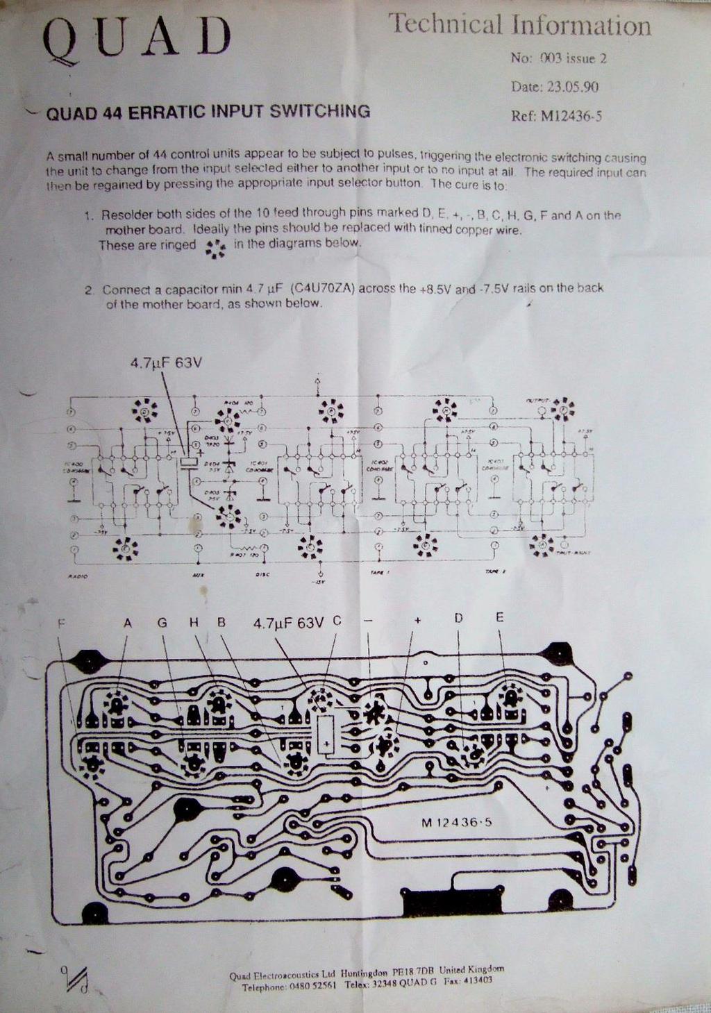
1 Upgrade/revision manual Quad 44 pre amplifier. V2.5 These are the illustrated step-by-step guidelines for upgrading your Quad 44 with the Dada Electronics upgrade-kits. The Quad 44 preamp was the first Quad preamplifier using op-amps and electronic switches. The input circuits where build as separate modules, allowing for more versatility. The input modules are interchangeable, so you could equip the unit with 5 pickup inputs or any other combination. From a technical design viewpoint the unit was the successor of the Quad 33; it has the same internal bus voltage of 100mV, DIN sockets in the first models and the 33 filter section. A lot can be said about the quality of the circuit design and the design parameters, but remember, this is from today s perspective! With the implementation of the Dada kits, the 44 will perform as it was intended by Quad and even better as we will use the latest in Opamp and switching technology. The 44 was produced from 1979 till 1989, units were built. Although there are a lot of internal versions, if you look at the outside only, there are two models, the first brown series and the later grey series. From serial number onwards, the tone and volume control circuits were copied from the Quad 34 preamp, which was introduced after the 44. Also, dual opamps were used in the CD/AUX-module. Although there are major internal circuit releases, three kits can cover these models with the standard input modules. For the non standard modules, in most cases the MC modules in a total of seven variations, ask us for a separate kit. The same applies for the other special parts like the relays. Based on the serial number and the module PCB numbers can supply the correct parts. Contact info@dadaelectronics.eu for special versions of the kit or specific components. We will do the upgrade step-by-step. For every step these guidelines will tell you what to do (in Underline) and give you some tips, tricks and advice (in Italics). You should have some soldering experience for bringing this project to a happy conclusion, but you don t have to be an electronics expert. If there are any problems, send an to info@dadaelectronics.eu with a clear description of the problem. Some pictures may help us understand the problem better. We will do our best to answer within 24 hours 7 days a week. When the project is completed, you will be listening to one of the best high-end pre-amplifiers ever made with a better-than-original Quad-sound. Components may change without notice. For diagrams and other useful information: download the service manual. Stefaan & Joost, April of 9
2 Step 1 The tools & the Components The tools you need: A good quality soldering iron with a fine point (max 30) Watt or a soldering-station. A desoldering-pump or desoldering station A micro cutting nipper, a wire-stripper and miniature pliers Philips n 2 and 1 screwdrivers Tin/lead solder wire A digital multimeter Kontakt LR PCB-cleaner and Kontakt 61 Contact-spray are very useful If you don t have these tools you can order them in the Dada Electronics web shop. The components in the Quad 44-kit: During the revision we will replace all electrolytic capacitors as well as the (single and dual) opamps and the electronic switches. Depending on the serial-number you will use kit I, II or kit III. To avoid switch oscillation and malfunction we will add a 4µ7 axial capacitor to the PSU board: see the Quad paper on this subject on page 5 of this manual. Serial number Kit I 2 of 9 Replace with: Tonecontrol: 4 x TL 071 OPA604 M iss 8 2 x 100uF 6.3V C522/ µF 10V 1 x 47uF 40V C528 47µF 63V Mother/PSUboard: 2 x 47uF 63V C402/403 47µF 63V M iss 4 2 x 1000uF axial C404/ µF 25V Axial 4u7 63 volt on PSU board extra 4,7µF 63V Axial 4 x 4066 CDC4066BNC See page 7 R400, R405 1Ohm R402, R Ohm Tape board 2 x 4 x TL071 OPA604 or LME49710 M12496 iss 3 4 x 100uF 6.3V C3/4 100µF 10V Disc board 2 x TL071 OPA604 or LME49710 M iss 5 2 x 2.2uF 50V C316/317 2,2µF 50V Radio board M iss 1 4 x TL071( 2 x Radio board) OPA604 or LME49710
3 Serial number Kit II 3 of 9 Replace with: Tonecontrol board: 4 x TL 071 OPA604 or LME49710 M iss 9 2 x 100uF 6.3V C522/ µF 10V Mother /PSUboard: 2 x 47uF 63V C402/403 47µF 63V M iss 5 2 x 1000uF axial C404/ µF 25V Axial 1x 100uF 16V C µF 16V 4u7 63 Volt on PSU board extra 4,7µF 63V Axial 4 x 4066 CDC4066BNC See page 7 R400, R405 1Ohm R402, R Ohm Tape board 2 x 4 x TL071 OPA604 or LME49710 M12496 iss 3 4 x 100uF 6.3V C3/4 100µF 10V Disc board 2 x TL071 OPA604 or LME49710 M iss 5 2 x 2.2uF 50V C316/317 2,2µF 50V Radio board 2 x TL071 OPA604 or LME49710 M iss 1 AUX board M iss 2 2 x TL071 OPA604 or LME49710 Serial number & Higher - Kit III Replace with: Tonecontrol board: 5 x TL 072 OPA2604 or LME49720 M iss 1 6 x 100uF 6.3V C702/703/706/707/731/ µF 10V Mother/PSU board: 2 x 47uF 63V C402/403 47µF 63V 2 x 1000uF axial C404/ µF 25V Axial 100uF 16V C µF 16V 4u7 63 volt on PSU board extra 4,7µF 63V Axial 4 x 4066 CDC4066BNC See page 7 R400, R405 1Ohm R402, R Ohm Tape board 2 x 4 x TL071 OPA604 or LME49710 M iss 3 4 x 100uF 6.3V C3/4 100µF 10V Disc board 2 x TL071 OPA604 or LME49710 M iss 5 2 x 2.2uF 50V C316/317 2,2µF 50V Radio board 2 x TL071 OPA604 or LME49710 M iss 2 CD/AUX board M iss 1 1 x TL072 OPA2604 or LME49720 All other Quad 44 components are also available from the Dada Electronics webshop

4 Dismantling the 44 and replacing the components Remove the cover. Remove the input modules. Remove the white plastic locator and the protective cardboard from the module rack. If you want easy access to the motherboard to which the input modules mate, remove it from the unit. You don t need to remove the tone-control board: you can solder the components while the board remains in place. Replace the electrolytic one by one. On the circuit boards there is in most cases no plus or minus indication. So make notes or pictures. The same applies to the op-amps and the switches: note where pin 1 was before you remove each op-amp, and fit the new op-amp the same way. You may indicate the + side of the electrolytic and the pin 1 location of the op-amps on the board with a pencil. There is an extra 4.7µF Axial electrolytic supplied in the kit. This is an official modification from Quad to prevent erratic switching, see the picture and the Quad paper for correct placement on the PSU board. On 44 above serial number it can be difficult to replace Ic701. Remove the front and the plastic on/off switch rod. Testing the amplifier If you have a scope and a sine wave-generator you can measure the output voltage and the input sensitivity of the amplifier. If you don t have this equipment it s not a problem. No calibration is necessary. And that s it. If there is any problem don t hesitate to send us an (info@dadaelectronics.eu). A picture and a good description will help to solve the problem. Stefaan & Joost 4 of 9
5 5 of 9

6 Placement of 4u7 capacitor on the motherboard 6 of 9

7 Extra information on further upgrading and fault situations. Tone control board On some Model I units, prior to serial 2401, users find it annoying that the unit is not silent at volume position zero, like the 34 pre amp. Change R500 and R501 from 22k to 6k8, change R502 and R503 from 6k8 to 2k2 on the tone control board. The output of the 44 is now at a -72dB level at position zero, not silent, but close! Power supply board In some cases the Psu is not delivering enough current to feed all the Op amps and the relay circuit, with a rattling relay at start up as the consequence. Replace R400 and R405 with 1 Ohm, R402 and R403 with 1500 Ohm. The resistors are in the kit, but only necessary when the rattling occurs. Low frequency oscillation. In some cases the modern Op Amps oscillate due to long power supply tracks and/or wiring. Placing a small capacitor between the plus and ground, and the minus and ground can solve this oscillation, the best place to this is at Ic500 and Ic501. Connect a small 100nF capacitor between pin 3 and 7, and 3 and 4. For 44 s above serial : The Ic number is Ic700a and Ic701a. The capacitors must be placed between pin 3 and 4, and between pin 3 and 8 because these are dual Op Amps. Op Amp layout Layout of tone control board above serial The next section gives information on further upgrades, beyond the standard kit. Radio Input board M12511 iss 1 and 2 Remove R204 and R205, and replace R202 and R203 with a wirelink. Aux Input board M12511 iss 2 Remove R606 and R607, and replace R604 and R605 with a wirelink. Quad did design the circuits like they are, because of Op Amps that could not cope with unity gain, with the replacement Op Amps; this is not a problem anymore. The modification reduces noise and distortion by increasing the local feedback. 7 of 9
 band B is the second significant figure band C is the third significant figure band D is the decimal multiplier band E indicates")
8 Color coding of resistors. To distinguish left from right there is a larger gap between the D and E bands. band A is the first significant figure of component value (left side) band B is the second significant figure band C is the third significant figure band D is the decimal multiplier band E indicates tolerance of value in percent Color A First figure B Second figure C Third figure 8 of 9 D Multiplier E Tolerance Black Brown ±1% Red ±2% Orange K Yellow K Green K ±0.5% Blue M ±0.25% Violet M ±0.1% Gray M ±0.05% White G Gold 0.1 ±5% Silver 0.01 ±10% None ±20% Example: Red, Red, Black, Red, Brown 220 X 100 = 22Kohm and 1% tolerance


9 The indentification of the plus and minus of electrolyte capacitors. In allmost all cases the minus is indicated with a long stripe with symbols at the side of the can in the color of the printed text. Also if the capacitor has wires, the minus wire is the shortest one! Capacitors with srcew terminals will have sometimes the stripe indication or have indications on top of the capacitor, if any doubts, contact us! Connecting capacitors in the wrong way could give a lot of damage. With axial capacitors there is an extra arrow indicating the minus wire, or there is a printed small ring around the body indicating the minus wire. Also the minus wire is direct connected to the aluminium body. The plus wire is sticking through the black plastic cap. Indication of the cathode of diodes and zener diodes The cathode will be indicated by a white, silver or black line on the body of the diode. 9 of 9
These are the illustrated step-by-step guidelines for upgrading your Quad 306 with the Dada Electronics upgrade-kit.
 Quad 306 DIY illustrated guidelines version 1.1 These are the illustrated step-by-step guidelines for upgrading your Quad 306 with the Dada Electronics upgrade-kit. We will replace all electrolytic capacitors,
Step 1 - Modifying the power-supply from 12 to 16 Volts Increasing the power-supply voltage to 16V increases the headroom and reduces distortion. Also
 Dada Electronics - Quad 33 Revision - Illustrated Guidelines V 2.4 First of all, thanks for your purchase of our upgrade kit! Hereunder, you will find the step-by-step guidelines for upgrading the Quad
MP3 audio amplifier. Build Instructions. Issue 2.0
 MP3 audio amplifier Build Instructions Issue 2.0 Build Instructions Before you put any components in the board or pick up the soldering iron, just take a look at the Printed Circuit Board (PCB). The components
TuBbika SMR-4-PLUS voicecard
 TuBbika SMR-4-PLUS voicecard Assembly instructions We assume you know soldering. If you don t, look first at this tutorial. Be patient! And if you have any doubt, head to the forum never be afraid to ask!
Installation instructions DC Protection and Delay unit, Version 1.2 The package should contain: A piece of normal gauge yellow wire for the AC connect
 Installation instructions DC Protection and Delay unit, Version 1.2 How does the unit work? Delay: Basically a capacitor is charged via a resistor, when the voltage of the capacitor reach a certain level,
High Power (15W + 15W) Stereo Amplifier
 Stereo Amplifier") High Power (15W + 15W) Stereo Amplifier Build Instructions Issue 1.0 Build Instructions Before you put any components in the board or pick up the soldering iron, just take a look at the Printed Circuit
High Power (15W + 15W) Stereo Amplifier Build Instructions Issue 1.0 Build Instructions Before you put any components in the board or pick up the soldering iron, just take a look at the Printed Circuit
Images Scientific OWI Robotic Arm Interface Kit (PC serial) Article
 Article") Images Scientific OWI Robotic Arm Interface Kit (PC serial) Article Images Company Robotic Arm PC Interface allows real time computer control and an interactive script writer/player for programming and
Images Scientific OWI Robotic Arm Interface Kit (PC serial) Article Images Company Robotic Arm PC Interface allows real time computer control and an interactive script writer/player for programming and
Universal Keying Adapter 3+
 Universal Keying Adapter 3+ The Universal Keying Adapter Version 3+ kit will allow you to key nearly any transmitter or transceiver with a straight key, electronic keyer, computer serial or parallel port
Button Code Kit. Assembly Instructions and User Guide. Single Button Code Entry System
 Button Code Kit Single Button Code Entry System Assembly Instructions and User Guide Rev 1.0 December 2009 www.alan-parekh.com Copyright 2009 Alan Electronic Projects Inc. 1. Introduction... 4 1.1 Concept
DELUXE STEREO AMPLIFIER KIT
 ESSENTIAL INFORMATION BUILD INSTRUCTIONS CHECKING YOUR PCB & FAULT-FINDING MECHANICAL DETAILS HOW THE KIT WORKS CREATE YOUR OWN SPEAKER DOCK WITH THIS DELUXE STEREO AMPLIFIER KIT Version 2.0 Build Instructions
Pacific Antenna Easy TR Switch Kit
 Pacific Antenna Easy TR Switch Kit Kit Description The Easy TR Switch is an RF sensing circuit with a double pole double throw relay that can be used to automatically switch an antenna between a separate
RECORD & PLAYBACK KIT
 ESSENTIAL INFORMATION BUILD INSTRUCTIONS CHECKING YOUR PCB & FAULT-FINDING MECHANICAL DETAILS HOW THE KIT WORKS ADD AN AUDIO MESSAGE TO YOUR PRODUCT WITH THIS RECORD & PLAYBACK KIT Version 2.1 Build Instructions
Installation/assembly manual for DCC/Power shield
 Installation/assembly manual for DCC/Power shield The DCC circuit consists of the following components: R1/R6 R2/R3 R4/R5 D1 C2 2 kω resistor ½ Watt (colour code Red/Black/Black/Brown/Brown) 10 kω resistor
Using solderless breadboards
 Page 1 of 9 Using solderless breadboards This document describes how to use the solderless breadboards available in the experimental didactic lab (LED, previously LADISPE) of Politecnico di Torino. 1 Setting
Connecting LEDs to the ADB I/O
 Application Note AN-2 By Magnus Pettersson September 26 1996 Connecting LEDs to the I/O Introduction The following notes are for those of you who are a bit inexperienced with hardware components. This
Pacific Antenna Two Tone Generator
 Pacific Antenna Two Tone Generator Description Our Two Tone Generator kit provides two non-harmonic, sine wave signals for testing audio circuits Outputs of approximately 700Hz and 1900Hz and the combination
3 pyro output datalogger altimeter with an ATmega 328 microcontroller Kit assembly instructions
 3 pyro output datalogger altimeter with an ATmega 328 microcontroller Kit assembly instructions Version date Author Comments 1.0 29/05/2013 Boris du Reau Initial version Rocket Type Micro-max Model Mid
solutions for teaching and learning
 RKAmp1 Component List and Instructions PCB layout Constructed PCB Schematic RKAmp1 Stereo Amplifier Page 1 Description The RKAmp1 stereo amplifier PCB has been designed around the 2 x 1watt stereo amplifier
Sample assessment task. Task details. Content description. Task preparation. Year level 9 Learning area Subject Title of task
 Sample assessment task Year level 9 Learning area Subject Title of task Task details Description of task Type of assessment Purpose of assessment Assessment strategy Evidence to be collected Suggested
Uzebox Kit Assembly Guide
 Uzebox Kit Assembly Guide V1.3 Page 1 of 18 Revision History Version Date Author Description 1.0 01-Nov-2012 A.Bourque Initial release 1.1 6-Nov-2012 A.Bourque Minor corrections 1.2 28-Jan-2014 A.Bourque
solutions for teaching and learning
 RKAmp3 Component List and Instructions PCB layout Constructed PCB Schematic RKAmp3 Stereo Amplifier Page 1 Description The RKAmp3 stereo amplifier PCB has been designed around the 2 x 7watt stereo amplifier
MINI-IO/IO-MODULE KIT Input/Output Module
 MINI-IO/IO-MODULE KIT Input/Output Module Simplicity Counts, Detail Matters. No part of this document may be reproduced, either mechanically or electronically, posted online on the Internet, in whole or
Dual LPG + Timbre RANDOM*SOURCE. Dual LPG / Timbre RANDOMSOURCE.NET
 Dual LPG + Timbre The Dual LPG + Timbre section is part of the Donks module and comprises a dual low pass gate based on the famous 292C as well as the equally famous Timbre circuit adjusted to +12V and
RC210 Repeater Controller Assembly Manual
 Arcom Communications 24035 NE Butteville Rd Aurora, Oregon 97002 (503) 678-6182 arcom@ah6le.net http://www.arcomcontrollers.com/ RC210 Repeater Controller Assembly Manual Hardware Version 3.3 Reproduction
AUDIO AMPLIFIER PROJECT
 Intro to Electronics 110 - Audio Amplifier Project AUDIO AMPLIFIER PROJECT In this project, you will learn how to master a device by studying all the parts and building it with a partner. Our test subject:
STAGE INTERCOM KIT 1.1 SPECIFICATION. General: The lower section is a small power amplifier designed to drive headphones or a small 8ohm speaker.
 STAGE INTERCOM KIT Version 2.1.1 - March 2018 - EduTek Ltd 1.0 DESCRIPTION This intercom module comprises of two separate circuits sharing the same supply. The upper section is a pre-amplifier designed
PicoTurbine Mark 8.3 Generator Field Controller Kit
 PicoTurbine Mark 8.3 Generator Field Controller Kit Based on a design published in Home Power magazine by Richard Perez. Used with permission. Reprint of original article included with kit. An easy-to-build
Schematic Diagram: R2,R3,R4,R7 are ¼ Watt; R5,R6 are 220 Ohm ½ Watt (or two 470 Ohm ¼ Watt in parallel)
") Nano DDS VFO Rev_2 Assembly Manual Farrukh Zia, K2ZIA, 2016_0130 Featured in ARRL QST March 2016 Issue Nano DDS VFO is a modification of the original VFO design in Arduino Projects for Amateur Radio by
Nano DDS VFO Rev_2 Assembly Manual Farrukh Zia, K2ZIA, 2016_0130 Featured in ARRL QST March 2016 Issue Nano DDS VFO is a modification of the original VFO design in Arduino Projects for Amateur Radio by
solutions for teaching and learning
 Circuit Construction Op-Amp Comparator Project The circuit diagram on the right is the circuit for your project, it is called an op-amp comparator circuit, it is called a comparator circuit as it compares
QRPGuys Digital Dial/Frequency Counter
 QRPGuys Digital Dial/Frequency Counter First, familiarize yourself with the parts and check for all the components. If a part is missing, please contact us and we will send one. You must use qrpguys.parts@gmail.com
Code Practice Oscillator (CPO)
") Code Practice Oscillator (CPO) Overview Many thanks for your purchase of this code practice oscillator or CPO, this guide is intended to allow you to quickly get operational. The CPO comprises an approx.
Code Practice Oscillator (CPO) Overview Many thanks for your purchase of this code practice oscillator or CPO, this guide is intended to allow you to quickly get operational. The CPO comprises an approx.
KDR00101 DMX Controlled Relay Kit
 KDR00101 DMX Controlled Relay Kit This is a DMX512-A relay kit using ANSI approved RJ-45 connectors for DMX networks. Power requirements are 12 Vdc @ 100 ma. The relay contact rating is 10 Amp @ 120 or
RC-210 Repeater Controller Assembly Manual
 Arcom Communications 24035 NE Butteville Rd Aurora, Oregon 97002 (503) 678-6182 arcom@ah6le.net RC-210 Repeater Controller Assembly Manual Hardware Version 3.0 Original Release Date September 13, 2004
Post Tenebras Lab. Written By: Post Tenebras Lab
 Post Tenebras Lab PTL-ino is an Arduino comptaible board, made entirely out of through-hole components. It is a perfect project to learn how to solder and start getting into the world of micro controllers.
Advanced Strobe 1.0 Kit
 Kit Instruction Manual Eastern Voltage Research, LLC December 2013, Rev 1 1 http://www.easternvoltageresearch.com Kit Introduction to the Kit Thank you for purchasing the Kit. If you are looking for a
Assembly Guide. LEDs. With these assembly instructions, you can easily build your own SWT16. All required components are included in this kit.
 Assembly Guide With these assembly instructions, you can easily build your own SWT16. All required components are included in this kit. You need the following tools: soldering iron, wire cutter and solder.
TKEY-1. CW touch key. (no electromechanical contacts) Assembly manual. Last update: June 20,
 Assembly manual. Last update: June 20,") TKEY-1 CW touch key (no electromechanical contacts) Assembly manual Last update: June 20, 2017 ea3gcy@gmail.com Updates and news at: www.ea3gcy.com Thanks for constructing the TKEY-1A CW touch key Have
TKEY-1 CW touch key (no electromechanical contacts) Assembly manual Last update: June 20, 2017 ea3gcy@gmail.com Updates and news at: www.ea3gcy.com Thanks for constructing the TKEY-1A CW touch key Have
Luxman DML replacement manual by PE1MMK (construction)
") Luxman DML replacement manual by PE1MMK (construction) 1. Dismantling Take your amplifier to a appropriate place to work on it, use a small cloth or plastic cover to place your amp on, otherwise you might
Luxman DML replacement manual by PE1MMK (construction) 1. Dismantling Take your amplifier to a appropriate place to work on it, use a small cloth or plastic cover to place your amp on, otherwise you might
The GENIE Light Kit is ideal for introducing simple lighting projects, such as an electronic die, a wearable badge or a night-time warning system.
 Introduction 1 Welcome to the GENIE microcontroller system! The GENIE Light Kit is ideal for introducing simple lighting projects, such as an electronic die, a wearable badge or a night-time warning system.
Morse Code Practice Oscillator
 Features Description Keyer speed range: Limited only by keying source True Sine wave tone output Tone Volume Control Tone Frequency Control Internal Speaker 1/8 External Speaker/Headphone Jack RCA Key
R e v. I - 4, N o v e m b e r 2 7,
 K2 OWNER S MANUAL ERRATA R e v. I - 4, N o v e m b e r 2 7, 2 0 1 5 M A K E T H E S E C H A N G E S T O Y O U R R E V. I M A N U A L B E F O R E Y O U B E G I N A S S E M B L Y 1. Page 20, Right Column,
Insert the male, 90 angled, 2x10 connectors into the corresponding 2x10 sockets and put them in place, flat under the PCB. Solder.
 MC624 Assembly guide Safety warning The kits are main powered and use potentially lethal voltages. Under no circumstance should someone undertake the realisation of a kit unless he has full knowledge about
KDR00301 DMX Controlled Relay Kit
 KDR00301 DMX Controlled Relay Kit This is a DMX512-A relay kit using ANSI approved RJ-45 connectors for DMX networks. Power requirements are 12 Vdc @ 200 ma. The relay contact rating is 10 Amp @ 120 or
RC-210 Repeater Controller Assembly Manual
 Arcom Communications 24035 NE Butteville Rd Aurora, Oregon 97002 (503) 678-6182 arcom@ah6le.net RC-210 Repeater Controller Assembly Manual Hardware Version 2.5 Reproduction or translation of any part of
MAIN PCB (The small one)
") THANKS FOR CHOOSING ONE OF OUR KITS! This manual has been written taking into account the common issues that we often find people experience in our workshops. The order in which the components are placed
THANKS FOR CHOOSING ONE OF OUR KITS! This manual has been written taking into account the common issues that we often find people experience in our workshops. The order in which the components are placed
Revised: Page 1
 Brought To You By And Designed By: Revised: 2017-05-07 Page 1 Features Of The Universal PSU Kit: Fits all standard Apple II and /// Power Supply Enclosures. (all parts included, user supplies household
3-slot Backplane For RC2014 User Guide
 3-slot Backplane For RC204 User Guide For module: SC6 version.0 Design and Documentation by Stephen C Cousins Edition.0.0, 208-0-7 CONTENTS OVERVIEW...2 PRINTED CIRCUIT BOARD... 4 SCHEMATIC... 6 WHAT YOU
XYLOPHONE KIT ESSENTIAL INFORMATION. Version 2.0 CREATE YOUR OWN ELECTRONIC MUSICAL INTRUMENT WITH THIS
 ESSENTIAL INFORMATION BUILD INSTRUCTIONS CHECKING YOUR PCB & FAULT-FINDING MECHANICAL DETAILS HOW THE KIT WORKS CREATE YOUR OWN ELECTRONIC MUSICAL INTRUMENT WITH THIS XYLOPHONE KIT Version 2.0 Build Instructions
K2 OWNER S MANUAL ERRATA. Rev. I - 7, March 19, 2017
 K2 OWNER S MANUAL ERRATA Rev. I - 7, March 19, 2017 MAKE THESE CHANGES TO YOUR REV. I MANUAL BEFORE YOU BEGIN ASSEMBLY OR ANNOTATE THE MANUAL TO REFER TO THIS ERRATA. 1. Page 20, Right Column: Under Inventory,
Tubbutec Sumtiple Kit Version Construction Manual
 Tubbutec Sumtiple Kit Version Construction Manual This document describes the construction of the Sumtiple Kit. The following parts are included: 1x Sumtiple PCB with SMD-Parts already soldered 1x Front
Uzebox Kit Assembly Guide
 Uzebox Kit Assembly Guide V1.7 Page 1 of 21 Revision History Version Date Author Description 1.0 01-Nov-2012 A.Bourque Initial release 1.1 6-Nov-2012 A.Bourque Minor corrections 1.2 28-Jan-2014 A.Bourque
BehringerMods.com. Instructions for modification of Behringer SRC analog inputs and outputs
 BehringerMods.com Instructions for modification of Behringer SRC analog inputs and outputs The following instructions will cover the details of fully modifying a unit with analog output and analog input
MAIN PCB (The small one with the square cut out from one side)
") THANKS FOR CHOOSING ONE OF OUR KITS! This manual has been written taking into account the common issues that we often find people experience in our workshops. The order in which the components are placed
THANKS FOR CHOOSING ONE OF OUR KITS! This manual has been written taking into account the common issues that we often find people experience in our workshops. The order in which the components are placed
Chill Interface PCB Assembly Instructions
 ExcelValley Chill Interface PCB Waveblaster Module MIDI Interface Board Chill Limited Edition V2 Assembly Kit Standalone midi interface board for Waveblaster synthesizer modules. Suitable for most Waveblaster
VG-305A AC Traffic Light Controller Kit
 Galak Electronics Electronic kits and components Website: GalakElectronics.com Email: sales@galakelectronics.com Phone: (302) 832-1978 VG-305A AC Traffic Light Controller Kit Thank you for your purchase
Transcendent Frequency Counter
 Transcendent Frequency Counter with blue 2 x 16 LCD display This manual will guide you how to assemble, test and operate this frequency counter KIT. Features: The transcendent counter has two input channels
Building the RGBW LED Controller
 Building the RGBW LED Controller A guide for the assembly and operation of your RGBW LED Controller. ver 3.1 Getting Started Parts list - You should have received the following parts: (1) Circuit Board,
K1EL Morse Code Practice Oscillator CPO
 Features This is an oscillator not a Morse keyer Input source can be a keyer or straight key Near Sine wave tone output CPO Tone Volume Control CPO Tone Frequency Control Use headphones or external speaker
KAA Watt x 2 Class-D Audio Amplifier Kit
 KAA10021 50 Watt x 2 Class-D Audio Amplifier Kit This amplifier kit uses Texas Instruments TPA3116D2 stereo audio amplifier IC for driving speakers up to 50 watts @ 4 ohm per channel in stereo mode and
BuffaloLabs WiFi Lantern Assembly guide version 1
 BuffaloLabs WiFi Lantern Assembly guide version 1 Needed equipment: Solder iron Solder wire Cutter Wire stripper (optional) Hot glue gun Overview of the components (not including USB cable and box panels)
solutions for teaching and learning
 RKOneAnalogue Component List and Instructions PCB layout Constructed PCB Schematic Diagram RKOneAnalogue Software Development PCB Page 1 Description The RKOneAnalogue software development PCB has been
IR TRANSMITTER BLOK PCB ASSEMBLY INSTRUCTIONS. Copyright EduTek Ltd Rev. 2
 IR TRANSMITTER BLOK PCB ASSEMBLY INSTRUCTIONS Copyright EduTek Ltd Rev. 2 Circuit Details The circuit is shown below with a parts list of components. Check through this list and identify each component.
Shack Clock kit. U3S Rev 2 PCB 1. Introduction
 Shack Clock kit U3S Rev 2 PCB 1. Introduction Thank you for purchasing the QRP Labs Shack Clock kit. This clock uses the Ultimate3S QRSS/WSPR kit hardware, but a different firmware version. It can be used
Assembly Instructions (8/14/2014) Your kit should contain the following items. If you find a part missing, please contact NeoLoch for a replacement.
 Your kit should contain the following items. If you find a part missing, please contact NeoLoch for a replacement.") NeoLoch NLT-28P-LCD-5S Assembly Instructions (8/14/2014) Your kit should contain the following items. If you find a part missing, please contact NeoLoch for a replacement. Kit contents: 1 Printed circuit
NeoLoch NLT-28P-LCD-5S Assembly Instructions (8/14/2014) Your kit should contain the following items. If you find a part missing, please contact NeoLoch for a replacement. Kit contents: 1 Printed circuit
DPScope SE Assembly Guide
 DPScope SE Assembly Guide Version 1.0 (Jan. 26, 2012) Congratulations for purchasing the DPScope SE oscilloscope kit! This guide will lead you through all the steps required to put it together so you ll
BATC Kit MTK2 for MiniTiouner
 BATC Kit MTK2 for MiniTiouner Serit FTS4335V NIM Converter Document Change Log 2017-02-22 v1.01 First release 2017-03-01 v1.04 Minor mods Serit FTS4335V, Converter and MiniTiouner (built by G4KLB) Serit
Content. Centura DIY Kit Instructions
 Centura DIY Kit Instructions 2017 Ceriatone Amplification http://www.ceriatone.com/ nik@ceriatone.com - for ordering purpose kilopp@hotmail.com - backup email address Content 1. Introduction 2. Schematic
SRI-02 Speech Recognition Interface
 SRI-02 Speech Recognition Interface Data & Construction Booklet The Speech Recognition Interface SRI-02 allows one to use the SR-07 Speech Recognition Circuit to create speech controlled electrical devices.
LED Knight Rider. Yanbu College of Applied Technology. Project Description
 LED Knight Rider Yanbu College of Applied Technology Project Description This simple circuit functions as a 12 LED chaser. A single illuminated LED 'walks' left and right in a repeating sequence, similar
UF-3701 Power Board Construction Guide
 Page 1/5 Soldering and Part Placement See the Chapter 3 of the MIT 6270 Manual for information on electronic assembly, including soldering techniques and component mounting. Construction Information All
DEV-1 HamStack Development Board
 Sierra Radio Systems DEV-1 HamStack Development Board Reference Manual Version 1.0 Contents Introduction Hardware Compiler overview Program structure Code examples Sample projects For more information,
QUASAR ELECTRONICS KIT No Hi-Fi PREAMPLIFIER WITH REMOTE CONTROL
 QUASAR ELECTRONICS KIT No. 1070 Hi-Fi PREAMPLIFIER WITH REMOTE CONTROL General Description This is a hi-fi STEREO preamplifier based on a single integrated circuit which employs a revolutionary new method
by illumicon APRSTRACKER Pietershoek XA Veldhoven The Netherlands fax
 by illumicon www.ezkits.eu APRSTRACKER Pietershoek 3 5503XA Veldhoven The Netherlands fax +31-40-2230020 Contents Introduction...3 Soldering Tips...3 Assembly...4 Schema...5 Connections...6 Adjustments...6
Figure 1 FS710 Front Panel
 INTRODUCTION The Model FS710 10 MHz AGC Distribution Amplifier provides seven sine wave outputs from a single 10 MHz source. Designed as an accessory to the FS700 LORAN Receiver, the FS710 AGC circuitry
BalloonSat Sensor Array
 BalloonSat Sensor Array The PICAXE-08M2 in the BalloonSat flight computer is a digital device. Being digital, it functions best with a series of on and off voltages and does not interact very well with
K8099 NIXIE CLOCK. * optional enclosure TKOK19 (black) - TKOK17 (white) ** optional plexiglass enlcosure B8099 ILLUSTRATED ASSEMBLY MANUAL
 - TKOK17 (white) ** optional plexiglass enlcosure B8099 ILLUSTRATED ASSEMBLY MANUAL") Total solder points: 230 + 74 Difficulty level: beginner 1 2 3 4 5 advanced NIXIE CLOCK K8099 ** * A unique combination of both vintage and modern electronics ILLUSTRATED ASSEMBLY MANUAL H8099IP-1 * optional
Total solder points: 230 + 74 Difficulty level: beginner 1 2 3 4 5 advanced NIXIE CLOCK K8099 ** * A unique combination of both vintage and modern electronics ILLUSTRATED ASSEMBLY MANUAL H8099IP-1 * optional
Noise Source Model 9751 Assembly and Using Manual
 Noise Source Model 9751 Assembly and Using Manual This second-generation 9700-series processing element for modular sound synthesizers is designed to provide great sound and excellent value. This module
ME 3210: Mechatronics Signal Conditioning Circuit for IR Sensors March 27, 2003
 ME 3210: Mechatronics Signal Conditioning Circuit for IR Sensors March 27, 2003 This manual and the circuit described have been brought to you by Adam Blankespoor, Roy Merril, and the number 47. The Problem:
GLiPIC Ver C Assembly manual Ver 1.0
 GLiPIC Ver C Assembly manual Ver 1.0 Last Rev 1.1 Oct 30, 2001 Author: Ranjit Diol Disclaimer and Terms of Agreement As with any kit, only the individual parts supplied are guaranteed against defects and
KDS Channel DMX Controlled Servo Kit
 KDS00801 8-Channel DMX Controlled Servo Kit This is a DMX512-A controlled servo kit using ANSI approved RJ-45 connectors for DMX networks. Power requirements are 8-20 VDC @ 50 ma. The board features an
Figure 1. The Programmable Flight Computer.
 The BalloonSat Flight Computer There are 22 parts in this BalloonSat flight computer, the heart of which is the PICAXE- 08M2. The PICAXE is a microcontroller; making the BalloonSat Flight Computer programmable.
Shack Clock kit PCB Revision: QCU Rev 1 or QCU Rev 3
 1. Introduction Shack Clock kit PCB Revision: QCU Rev 1 or QCU Rev 3 Thank you for purchasing this QRP Labs Shack Clock kit. The kit uses the same PCB and bag of components as some other QRP Labs kits.
Figure 1. The BalloonSat Programmable Flight Computer.
 The Dissertation BalloonSat Flight Computer There are 21 parts in this BalloonSat flight computer, the heart of which is the PICAXE- 08M2. The PICAXE is a microcontroller; making the BalloonSat Flight
Assembly Instructions for the KA Electronics IGFO Input Gain Filter Output Board
 Assembly Instructions for the KA Electronics IGFO Input Gain Filter Output Board IGFO PC Board Stuffing Guide Install IC sockets Place the PC Board on the work bench silkscreen side face up. Place ten
Manual Version March 2007
 Manual Version 1.1 - March 2007 Page 1 Table of Contents Section1: 6922 Line Board Build... 3 6922 Line Board Version Notes... 5 6922 Line Board Build - HARD-WIRED VERSION... 5 Final Connections and Checks
Assembly Instructions IV-11 DCF, melody
 This IV-11 clock is the next generation to the IV-11 Quartz, DCF, melody. This is not a beginner kit. It requires soldering experience on the IV-18 and the IV-3A board The switching power supply wall adapter
LCD Prototype Circuit on Solderless Breadboard. 840 Pin Solderless Breadboard (http://www.digikey.com/ # ND)
") Solderless Breadboard Tutorial Cornerstone Electronics Technology and Robotics I Week 3 Solderless Breadboards: o Solderless breadboards are commonly used in experimentation or to make a prototype of a
Solderless Breadboard Tutorial Cornerstone Electronics Technology and Robotics I Week 3 Solderless Breadboards: o Solderless breadboards are commonly used in experimentation or to make a prototype of a
Creep Cluster Build Document. V5 - November 2018
 Creep Cluster Build Document. V5 - November 2018 Dual triangle oscillators are hard-switched by a fast squarewave. Then the signal goes into a resonant lowpass filter. Sounds vary from deep rumbling drones
BMC24. MIDI TO GATE CONVERTER DOCUMENTATION. This documentation is for use with the "Euro Style" bottom board.
 BMC24. MIDI TO GATE CONVERTER DOCUMENTATION. This documentation is for use with the "Euro Style" bottom board. A. USING THE MIDI TO GATE CONVERTER B. PARTS LIST C. BUILDING INSTRUCTIONS D. SCHEMATICS Revision.
Sierra Radio Systems. Making a Keyer with the. HamStack. Project Platform
 Sierra Radio Systems Making a Keyer with the HamStack Project Platform Introduction The HamStack Project Board includes primary interface elements needed to make a high quality CW keyer. Using the LCD
4.1 Parts and Components... IV Assembly Tips... IV Assembly Precautions... IV Required Tools, Equipment and Materials..
 IV PERSONALITY MODULE ASSEMBLY 4.1 Parts and Components............ IV-1 4.2 Assembly Tips............... IV-1 4.3 Assembly Precautions............ IV-1 4.4 Required Tools, Equipment and Materials.. IV-1
TEMPEST PROJECT NAME. BASED ON Friedman BE-OD / Dirty Shirley. BUILD DIFFICULTY Intermediate. DOCUMENT VERSION Amp-Like Distortion 1.0.
 PROJECT NAME TEMPEST BASED ON Friedman BE-OD / Dirty Shirley BUILD DIFFICULTY Intermediate EFFECT TYPE DOCUMENT VERSION Amp-Like Distortion.0. (09-0-08) PROJECT SUMMARY A pedal recreation of the Friedman
Revision B, February 14, Copyright 2009, Elecraft, Inc. All Rights Reserved
 K3 EXTERNAL ALC MODIFICATION Revision B, February 14, 2009 Copyright 2009, Elecraft, Inc. All Rights Reserved Introduction MCU firmware release from 1.99 with DSP firmware release from 1.76 provide the
Connecting igaging DigiMAG Scales to the Caliper2PC Interface A step by step Guide
 What is an igaging DigiMAG Scale? The igaging DigiMAG are digital linear scales that are easily connectable to the Caliper2PC interface. They consist of two parts, the encoder and the readout unit. The
PICAXE EXPERIMENTER BOARD (AXE090)
") (AXE00) Description: The PICAXE experimenter board allows circuits for any size/revision of PICAXE chip ( / / ) to be quickly tested using a prototyping breadboard. The experimenter board provides power
(AXE00) Description: The PICAXE experimenter board allows circuits for any size/revision of PICAXE chip ( / / ) to be quickly tested using a prototyping breadboard. The experimenter board provides power
RC Tractor Guy Controller V2.1 Assembly Guide
 RC Tractor Guy Controller V. Assembly Guide Features 0 Push button inputs Dual axis thumb sticks with built-in push button Rotary encoders with built-in push button MCU Socket to suit Meduino Mega 560
Strain gauge Measuring Amplifier GSV-1A8. Instruction manual GSV-1A8, GSV-1A8USB, GSV-1A16USB
 Strain gauge Measuring Amplifier GSV-1A8 Instruction manual GSV-1A8, GSV-1A8USB, GSV-1A16USB GSV-1A8USB SubD1 (front side) GSV-1A8USB M12 (front side) GSV-1A16USB (rear side) GSV-1A8USB K6D (front side)
EE 354 August 1, 2017 Assembly of the AT89C51CC03 board
 EE 354 August 1, 2017 Assembly of the AT89C51CC03 board The AT89C51CC03 board comes as a kit which you must put together. The kit has the following parts: No. ID Description 1 1.5" x 3.25" printed circuit
Bill of Materials: 8x8 LED Matrix Driver Game PART NO
 8x8 LED Matrix Driver Game PART NO. 2171031 This Game Maker II kit is a game design platform using a single color 8x8 matrix LED without the need for a shift register or expensive Arduino. The kit includes
Snail Gear Building instructions V1.0
 Snail Gear Building instructions V1.0 Table of contents Components... 3 PCB layout... 4 General guideline for components... 5 General building tips... 5 Modifications... 6 Biasing... 7 Off board wiring...