Programmable Control. Name Class Teacher. Ellon Academy Technical Faculty
|
|
|
- Austin Griffin
- 6 years ago
- Views:
Transcription


1 Programmable Control Name Class Teacher Ellon Academy Technical Faculty

2 Learning Intentions o Gain the ability to design and evaluate solutions to engineering problems in a range of contexts o I will gain knowledge and understanding of key concepts related to electronic and microcontroller-based systems, and their application o To know what a microcontroller is and how its used o I will know advantages and disadvantages of microcontroller based control systems compared to a hard-wired electronic equivalent Success Criteria o I can explain what a microcontroller is, how it works and can give examples of where they are used o I can state the advantages & disadvantages of using control systems in industry. o I can explain the following terms; RAM, ROM, ALU, EEPROM, I/O port, bus and clock. o I can use and understand binary. o I can convert binary to decimal and vice versa. o I can identify and use various input and output transducer devices. o I can use correct symbols (start, stop, input, output, branch, loop) to construct flowcharts showing solutions to simple control programs, involving time delays, continuous and fixed loops o I can use suitable commands, including high, low, for next, if then, pause, end (or their equivalents) to construct programs to solve simple control problems, involving time delays, continuous and fixed loops o I can use the computer and stamp controller to test my programs 1 To access video clips that will help on this course go to
3 Electronic Control Systems Many electronic devices have been developed to make life easier, safer, to help with work and for entertainment purposes. Some devices are purely electronic devices (for example a digital watch) however many of these devices also control mechanisms (for example the eject mechanism in a video recorder) and so can be described as mechatronic devices. Both electronic and mechatronic devices all have one thing in common they are all electronic control systems. System diagram Input Process Output A system diagram is a more detailed block diagram that also shows the real world input signal (for example light and heat) and the real world output signals (for examples movement or sound). Example - The system diagram for a warning device for a freezer in a restaurant would be drawn as shown below: Heat Temp Sensor Driver Buzzer Sound Or to put it another way: INPUT INPUT TRANSDUCER PROCESS OUTPUT TRANSDUCER OUTPUT Input transducers are electronic devices that detect changes in the real world and send signals into the process block of the electronic system. Output transducers are electronic devices that can be switched on and off by the process block of the electronic system. 2

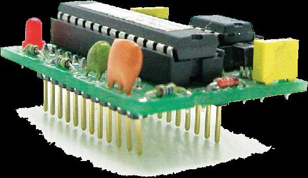
4 The Stamp Controller The Stamp software runs on a computer and allows you to use the computer keyboard to type in programs. The stamp controller runs programs that have been downloaded to it. It has indicator L.E.D.s to show which inputs and outputs are off or on, and has connectors for the input and output modules. The brain of the stamp controller board is the 18-pin micro controller chip in the centre of the board. Micro controller A micro controller is often described as a computer on a chip. Microcontrollers have a controller and memory all built into a single chip. As they are small, inexpensive they can easily be built into other devices to make these products more intelligent and easier to use. Microcontrollers are usually programmed for a specific electronic product for instance, a microwave oven may use a single microcontroller to process information for all its electronic devices. By altering the microcontroller program the same brand of chip can do many different tasks. 3

5 Advantages of using microcontrollers in a product design are: Increased reliability and reduced quantity of stock (as one microcontroller replaces several parts) Simplified product assembly and smaller end products Greater product flexibility and adaptability since features are programmed into the microcontroller and not built into the electronic hardware Rapid product changes or development by changing the program and not the electronic hardware Inside a Microcontroller The brain of the stamp controller system is the 18 pin micro controller in the centre of the board. Although micro controllers are relatively cheap, they are very complex devices containing many thousands of transistors, resistors and other electronic components. The main features of the micro controller are shown in the block diagram; 4
6 ROM The ROM (read only memory) contains the operating instructions for the micro controller. The ROM is programmed before the micro controller is installed in the target system, and the memory retains the information even when the power is removed. RAM The Ram (random access memory) is temporary memory used for storing information whilst the program is running. This is normally used to store mathematical answers that the micro controller comes out with as it is working. This memory is volatile, which means that as soon as the power is disconnected the contents of the memory are lost. ALU The processing unit (full name arithmetic and logic unit ALU) is the control centre of the micro controller. It operates by reading instructions from the ROM and then carrying out the mathematical operations for each instruction. Clock The clock circuit controls the speed at which these operations occur. The clock circuit within the micro controller synchronises all the internal blocks (ALU, ROM, RAM, etc) so that the whole system works correctly. Buses Information is carried between the various blocks of the micro controller along groups of wires called buses. The data bus carries data between ALU and RAM and the program bus carries the program instructions from the ROM to the ALU. EEPROM EEPROM (Electrically Erasable Programmable Read Only Memory) is a type of memory that can be reprogrammed when desired, but it also keeps the program when the power supply is removed. This means the stamp controller will start to run the program currently in the memory whenever the power supply is connected. 5
7 Flowcharts Flowcharts are commonly used to explain how a program works. As flowcharts are drawn graphically they often make programs easier to understand. A flowchart should be drawn for each program you develop. Start/stop symbol The start/stop symbol shape is a rectangle with rounded ends. Each flow chart must contain one start and usually one stop symbol unless it is a continuous loop. Start/Stop Wait symbol The wait symbol is a rectangle. The text inside the symbol explains how long the time delay is. Wait x seconds Outputs symbol The outputs symbol is a parallelogram. The text inside the symbol explains which output pins are switched on or off at any time. Switch on Decision Box The Decision box is a diamond. The program uses this to check if something has been completed. Repeated x times? No Yes 6
8 Continuous loop Sometimes it is necessary to create programs that loop forever, as is the case with traffic lights. There is no stop symbol because the program never ends! Example Start Red Light ON Task 1 Write out the flowchart for making a cup of tea Wait 6 secs Red Light OFF Green Light ON Wait 6 secs Yellow Light ON Wait 2 Secs Green Light OFF Yellow Light OFF Wait 1 Sec 7
9 Task 2 Set of temporary traffic lights is required for a system of road works. Red Red and Amber Green Amber 10s 2s 10s 2s Draw a flow chart for the lights sequence shown above by one set of traffic lights. Use the times given in the table. 8
10 Task 3 A microwave operates with the following sequence. Draw a flowchart for this sequence. 1. Light on 2. Turntable on 3. Magnetron on 4. Wait 30s 5. Magnetron off 6. Wait 10s 7. Turntable off 8. Buzzer on 9. Wait 0.5s 10. Buzzer off 11. Light off 9
11 Writing a programme Once a flowchart has been drawn it is necessary to convert it into the stamp controller programming language, which is called PBASIC A PBASIC program for the flowchart shown on the previous page is: main: high 7 pause 6000 low 7 high 5 pause 6000 high 6 pause 2000 low 5 low 6 goto main end ' switch pin 7 (red) on ' wait for 6seconds ' switch pin 7(red) off switch pin 59(green) on ' wait for 6 seconds ' switch pin 6(yellow) on ' wait for 2 seconds ' switch pin 5(green) off ' switch pin 6 (yellow) off return to start ' end the program An explanation after the apostrophe (') symbol makes each line of a PBASIC program much easier to understand. These comments are ignored by the computer when it downloads a program to the stamp controller. A label (for example main: in the program above) can be any word (apart from keywords such as high ), but it must begin with a letter. When the label is first defined it must end with a colon (:). The colon tells the computer that the word is a new label. Task 4 Key in the program above into PICAXE and test. Would this program be suitable for a traffic light system? If not how could you improve it? Test your new design in PICAXE 10
12 Symbols and Labels When writing the computer programs for our flowcharts it can sometimes be hard to remember which pins are connected to which devices. The symbol command can then be used at the start of a program to rename the inputs and outputs. In a normal program there will be a main program, which includes many mini programs. Mini programs or sub procedures are often used to separate the program into small sections to make it easier to understand. Subprocedures that complete common tasks can also be copied from program to program to save time. Example symbol red = ouput 7 symbol buzzer = output6 symbol counter = b0 rename output 7 red rename output 6 buzzer define a counter using variable b0 main: flash: noise: gosub flash gosub noise goto main end for counter = 1 to 25 switch on red pause 50 switch off red pause 50 next counter return switch on buzzer wait 2 switch off buzzer return make label called main call the sub-procedure flash loop back end of the main program make a sub-procedure called flash start a for.next loop red LED on wait 0.05 seconds red LED off wait 0.05 seconds next loop return from the sub-procedure make a sub-procedure called noise buzzer on wait 2 seconds buzzer off return from the sub procedure 11

13 Task 5 A laser cutting machine is used to cut sheet steel, as shown in the photograph below. The laser is positioned by motors A and B which are operated by a microcontroller. Input and output connections to the microcontroller are shown in the table below. The cutter is required to perform the following sequence of operations: 1: Switch on the laser 2: Move right for 0 5 seconds 3: Move forward for 0 5 seconds 4: Repeat steps 2 and 3 four times 5: Switch off laser and motors 12
14 Task 5 (Continued) (a) Complete the system flowchart below, to produce the required sequence of operations. The flowchart must include appropriate pin numbers. You may use information from the National 4/5 Data Booklet provided. 13
15 For next loop It is often useful to repeat the same part of a program a number of times, for instance when flashing an LED. In these cases a for next loop can be used. In this flowchart the LED connected to output pin 7 is flashed on and off five times. The number of times the code has been repeated is stored that is, stored in the RAM memory of the stamp controller. There are 10 available variables, labelled b0 to b9, which can be used in this way. These variables can also be renamed using the symbol command to make them easier to remember. START SET COUNTER = 5 SWITCH PIN 7 HIGH WAIT 1 s SWITCH PIN 7 LOW WAIT 1 s HAVE WE LOOPED 5 TIMES? STOP Task 6 Key in, download and run the following program. symbol counter = b0 symbol red = 7 ' define the variable counter ' define pin 7 with the name red main: for counter = 1 to 5 high red pause 1000 low red pause 1000 next counter end ' start a for next loop ' switch pin 7 high ' wait for 1 second ' switch pin 7 low ' wait for 1 second ' end of for next loop ' end program 14
16 Task 7 A microcontroller is used to operate an automatic window cleaning system. Input and output connections to the microcontroller are shown in the table below. 15
17 Task 7 (continued) Write a program to control the window cleaner. 16

18 Connecting output transducers The stamp controller can only drive low-power devices, such as LEDs, directly. It cannot drive devices such as lamps, buzzers, solenoids or motors directly because these devices require a higher current to operate. A common way to drive these devices is with a transistor, as shown in the diagram above. In this case the lamp is controlled by the transistor switching on and off. The Output Driver The output driver module provides four transistor outputs, as in the circuit shown above. Instead of using four separate transistors, the output driver uses an integrated circuit called the ULN2803A, which contains all the transistors in one 18-pin chip. To use the transistor outputs, the output device should be connected between the screw-terminal numbered output (4 7) and a V+ connection. The positive (red) wire on polarised devices (for example a buzzer) should be connected to the V+ connection. The white 6-pin header beside the screw terminals allows a stepper motor or control model to be connected easily to all four of the outputs. 17
19 The Motor Driver The output driver module also contains a second integrated circuit called the L293D push pull driver. This chip allows forward and reverse control of two d.c. motors. Each motor output uses two of the stamp controller output pins to control the direction of rotation of the motor. Pin 4 Pin 5 Motor A Pin 6 Pin 7 Motor B off off halt off off halt off on forwards off on forwards on off backwards on off backwards on on halt on on halt To use the push pull motor output, the motor should be connected between the screw terminals labelled A or B. If the motor turns in the opposite direction to that expected, the two motor wires should be swapped over. STAMP CONTROLLER OUTPUT DRIVER MODULE 18
20 Speed Control of D.C. Motors There are two ways to control the speed of a D.C. motor. The simplest is to vary the voltage applied to the motor. If, for instance, 3 V is applied to a small D.C. motor it will rotate at a lower speed than if 5 V were applied. Unfortunately the turning power (torque) of the motor will also drop, which means the whole motor system will be less powerful. The second way to control the motor is to always apply the full voltage (for example 5 V) across the motor, but then to switch the power supply on and off rapidly. As the power supply is off some of the time, the motor does not receive as much power and so the motor turns more slowly. The advantage of this system is that the torque remains quite high. This system is called pulse-width modulation (PWM). The time that the power supply is switched on is called the mark time, and the time that the motor is switched off is called the space time. By varying the on (mark)-to-off (space) ratio, the speed of the motor can be varied. MARK Voltage 0 SPACE Time 19
21 Task 8 Connect 2 motors to the output driver module as shown in the diagram. STAMP CONTROLLER OUTPUT DRIVER MODULE The high and low commands can be used to switch the output pins and control the motors forward, backward and halt. main: high 5 high 7 pause 1000 low 5 low 7 pause 1000 high 4 high 6 pause 1000 low 4 low 6 goto main ' make a label called main ' motor A forward ' motor B forward ' wait 1 second ' motor A halt ' motor B halt ' wait 1 second ' motor A backward ' motor B backward ' wait 1 second ' motor A halt ' motor B halt ' jump back to the start Key-in the program listed above, and then download it to the stamp controller. The motors should start moving. 20
22 Task 9 Connect a d.c. solar motor across the V+ and 7 terminals on the output driver module. This will provide an interfacing circuit as shown. a) Key in, download and run the program listed below. This program drives the motor at approximately half speed, as the space (off time) is twice the length of the mark (on time). Note that you must use pause delays, as the power supply must switch on and off very quickly (wait delays would be too long). main: high 7 pause 5 low 7 pause 10 goto main ' make a label called main ' output high ' wait 5 ms ' output low ' wait 10 ms ' jump back to the start b) Try out different speeds (by experimenting) by altering the length of the pause delays. c) Describe the advantages and disadvantages of using PWM speed control. 21
 switch connections.")
23 The Input Module The input module provides the interfacing circuits required to connect switches and sensors to the stamp controller. When the slide switch on the input module is up the input module provides four digital (on/off) switch connections. These can be used to connect input switches (for example a microswitch) to the stamp controller. The switches can be connected through the screw-terminal blocks or through the white push-on headers. Input pins 0 and 1 have on-board test switches. These allow programs to be tested without the need to connect external switches. Digital sensors A digital sensor is a simple switch type sensor that can only be on or off. 5 V VOLTAGE 0 V Common examples of a digital sensor are: microswitches push-and-rocker switches reed switches. TIME 22

24 Task 10 Key in, download and run the program listed below. This program makes output pin 7 flash every time the push-switch on input pin 0 is pushed. main: if pin0 =1 then flash goto main ' make a label called main ' jump if the input is on ' else loop back around flash: high 7 pause 2000 low 7 goto main ' make a label called flash ' switch output 7 on ' wait 2 seconds ' switch output 7 off ' jump back to start In this program the first three lines make up a continuous loop. If the input is off the program just loops around time and time again. If the switch is then pushed, the program jumps to the label called flash. The program then switches pin 7 on for two seconds before returning to the main loop. Note carefully the spelling in the if then line pin0 is all one word (without a space). Note also that only the label is placed after the command then no other words apart from a label are allowed. 23

25 Task 11 Develop a PBASIC program that will carry out the instructions shown in the flowchart above. Use the following pin configuration. Input connection Pin Output connection 7 red light 6 amber light 5 green light start switch 0 START GREEN LED ON SWITCH PUSHED? Y GREEN LED OFF AMBER LED ON WAIT 3 s N GREEN LED OFF RED LED ON WAIT 4 s AMBER LED ON WAIT 2 s RED/AMBER LED OFF GREEN LED ON 24
26 Task 12 A music venue has a system to cut off the power supply if a band plays too loudly. The system is operated by a microcontroller. Specification The system must: switch on a warning light if the sound level is too high flash the light 10 times (on for half a second then off for half a second) reset the system if the sound level is then ok cut off the power if the sound level is still too high. Load the following simulation into Yenka to see if it does what is expected. 25
27 Task 12 (Continued) a) Describe the tests you carried out and how the circuit actually performed. b) Compare the circuit s performance to the specification. Draw meaningful conclusions and where appropriate suggest possible improvements or further work. 26
28 Task 12 (Continued) c) Write the program for this circuit below. d) Take a photograph of your completed circuit and glue below 27
Revised Standard Grade Technological Studies. Programmable Control
 Revised Standard Grade Technological Studies Programmable Control Contents Students Notes 1 Section 1: Electronic Control Systems 3 Section 2: The Stamp Controller 11 Section 3: Inside a Microcontroller
INTRODUCTION TO THE PICAXE SYSTEM
 INTRODUCTION TO THE PICAXE SYSTEM A PIC microcontroller is often described as a computeronachip. It is an integrated circuit that contains memory, processing units, and input/output circuitry in a single
Microprocessors/Microcontrollers
 Microprocessors/Microcontrollers A central processing unit (CPU) fabricated on one or more chips, containing the basic arithmetic, logic, and control elements of a computer that are required for processing
Unit 2. Computer Control. PIC stands for PROGRAMMABLE INTERFACE CONTROLLER. A PIC chip takes in input signals and then controls output transducers
 Unit 2 Computer Control PIC stands for PROGRAMMABLE INTERFACE CONTROLLER A PIC chip takes in input signals and then controls output transducers Name: Form: 2 ASIC or Application Specific Integrated Circuits
Contents: revolution SECTION 3 - MICROCONTROLLER INTERFACING CIRCUITS MICROCONTROLLER INTERFACING CIRCUITS.
 1 Section 3 Contents: SECTION 3 - About this manual... 2 Microcontroller Interfacing Circuits... 3 What is a PIC Microcontroller?... 3 Interfacing to the PIC Microcontroller... 3 Note on the BASIC Code
09/05/2014. Engaging electronics for the new D&T curriculum. Geoff Hampson Managing Director of Kitronik. Presentation overview
 Presentation overview Engaging electronics for the new D&T curriculum Geoff Hampson Managing Director of Kitronik What to include Free web resources Electronic project ideas Using programmable components
Programmable timer PICAXE programming editor guide Page 1 of 13
 Programmable timer PICAXE programming editor guide Page 1 of 13 This programming guide is for use with: A programmable timer board. PICAXE programming editor software. When the software starts a menu is
 Chapter 1 Microprocessor architecture ECE 3120 Dr. Mohamed Mahmoud http://iweb.tntech.edu/mmahmoud/ mmahmoud@tntech.edu Outline 1.1 Computer hardware organization 1.1.1 Number System 1.1.2 Computer hardware
Robotic Systems ECE 401RB Fall 2006
 The following notes are from: Robotic Systems ECE 401RB Fall 2006 Lecture 13: Processors Part 1 Chapter 12, G. McComb, and M. Predko, Robot Builder's Bonanza, Third Edition, Mc- Graw Hill, 2006. I. Introduction
ELECTRONIC DICE CHIP FACTORY ELECTRONIC DICE PROJECT. What is a microcontroller? Example use of a microcontroller.
 1 ELECTRONIC DICE What is a microcontroller? A microcontroller is often described as a 'computer-on-a-chip'. It can be used as an electronic brain to control a product, toy or machine. The microcontroller
Chapter 1. Microprocessor architecture ECE Dr. Mohamed Mahmoud.
 Chapter 1 Microprocessor architecture ECE 3130 Dr. Mohamed Mahmoud The slides are copyright protected. It is not permissible to use them without a permission from Dr Mahmoud http://www.cae.tntech.edu/~mmahmoud/
Lecture Objectives. Introduction to Computing Chapter 0. Topics. Numbering Systems 04/09/2017
 Lecture Objectives Introduction to Computing Chapter The AVR microcontroller and embedded systems using assembly and c Students should be able to: Convert between base and. Explain the difference between
MicroProcessor. MicroProcessor. MicroProcessor. MicroProcessor
 1 2 A microprocessor is a single, very-large-scale-integration (VLSI) chip that contains many digital circuits that perform arithmetic, logic, communication, and control functions. When a microprocessor
Technological Studies Systems and Control Teacher/Lecturer Notes and Solutions to Assignments Higher
 Technological Studies Systems and Control Teacher/Lecturer Notes and Solutions to Assignments Higher 4559 Spring 1999 HIGHER STILL DET: Technological Studies Systems and Control Teacher/Lecturer Notes
SANKALCHAND PATEL COLLEGE OF ENGINEERING, VISNAGAR. ELECTRONICS & COMMUNICATION DEPARTMENT Question Bank- 1
 SANKALCHAND PATEL COLLEGE OF ENGINEERING, VISNAGAR ELECTRONICS & COMMUNICATION DEPARTMENT Question Bank- 1 Subject: Microcontroller and Interfacing (151001) Class: B.E.Sem V (EC-I & II) Q-1 Explain RISC
BalloonSat Sensor Array
 BalloonSat Sensor Array The PICAXE-08M2 in the BalloonSat flight computer is a digital device. Being digital, it functions best with a series of on and off voltages and does not interact very well with
HARDWARE. There are a number of factors that effect the speed of the processor. Explain how these factors affect the speed of the computer s CPU.
 HARDWARE hardware ˈhɑːdwɛː noun [ mass noun ] the machines, wiring, and other physical components of a computer or other electronic system. select a software package that suits your requirements and buy
HUB-ee BMD-S Arduino Proto Shield V1.1
 HUB-ee BMD-S Arduino Proto Shield V1.1 User guide and assembly instructions Document Version 0.5 Introduction & Board Guide 2 Schematic 3 Quick User Guide 4 Assembly Guide 6 Kit Contents 7 1) Diodes and
Introduction to microcontrollers
 Page 1 Page 2 Contents Introduction 2 Worksheet 1 - Switch on the LED 3 Worksheet 2 - Make the LED flash 5 Worksheet 3 - Keep the LED lit for a short time 7 Worksheet 4 - Set up a latch 9 Worksheet 5 -
Introduction to Microcontrollers
 Introduction to Microcontrollers Embedded Controller Simply an embedded controller is a controller that is embedded in a greater system. One can define an embedded controller as a controller (or computer)
THE MICROCOMPUTER SYSTEM CHAPTER - 2
 THE MICROCOMPUTER SYSTEM CHAPTER - 2 20 2.1 GENERAL ASPECTS The first computer was developed using vacuum tubes. The computers thus developed were clumsy and dissipating more power. After the invention
Project Planning. Module 4: Practice Exercises. Academic Services Unit PREPARED BY. August 2012
 Project Planning PREPARED BY Academic Services Unit August 2012 Applied Technology High Schools, 2012 Module Objectives Upon successful completion of this module, students should be able to: 1. Select
Goal: We want to build an autonomous vehicle (robot)
") Goal: We want to build an autonomous vehicle (robot) This means it will have to think for itself, its going to need a brain Our robot s brain will be a tiny computer called a microcontroller Specifically
Goal: We want to build an autonomous vehicle (robot) This means it will have to think for itself, its going to need a brain Our robot s brain will be a tiny computer called a microcontroller Specifically
ConText "Control by Text"
 ConText "Control by Text" Installation and Users Manual Available exclusively from PC Control Ltd. www.pc-control.co.uk 2016 Copyright PC Control Ltd. Revision 1.4 Contents 1. Introduction 2. Software
XYLOPHONE KIT ESSENTIAL INFORMATION. Version 2.0 CREATE YOUR OWN ELECTRONIC MUSICAL INTRUMENT WITH THIS
 ESSENTIAL INFORMATION BUILD INSTRUCTIONS CHECKING YOUR PCB & FAULT-FINDING MECHANICAL DETAILS HOW THE KIT WORKS CREATE YOUR OWN ELECTRONIC MUSICAL INTRUMENT WITH THIS XYLOPHONE KIT Version 2.0 Build Instructions
AXE033 SERIAL/I2C LCD & CLOCK
 AXE033 SERIAL/I2C LCD & CLOCK The serial LCD and clock module allows microcontroller systems (e.g. PICAXE) to visually output user instructions or readings, without the need for a computer. This is especially
Instruction Manual for BE-SP3 Circuit. 10/21/07
 Page 1 of 54 Instruction Manual for BE-SP3 Circuit. 10/21/07 Page 1 Index: Page 2 BE-SP3 Circuit Specifications. Page 3-4 Intro to the BE-SP3. Page 5 Basics of serial to parallel. Page 6-7 ASCII Code.
Ali Karimpour Associate Professor Ferdowsi University of Mashhad
 AUTOMATIC CONTROL SYSTEMS Ali Karimpour Associate Professor Ferdowsi University of Mashhad Main reference: Christopher T. Kilian, (2001), Modern Control Technology: Components and Systems Publisher: Delmar
CREATED BY M BILAL & Arslan Ahmad Shaad Visit:
 CREATED BY M BILAL & Arslan Ahmad Shaad Visit: www.techo786.wordpress.com Q1: Define microprocessor? Short Questions Chapter No 01 Fundamental Concepts Microprocessor is a program-controlled and semiconductor
MIAC-01 Now you are in control
 Page 1 Now you are in control General purpose industrial controller Full graphical programming language supplied A wide variety of applications Page 2 Introduction What does it do? MIAC (Matrix Industrial
revolution How does the ibutton work? Full kit including PCB, PICAXE-08M chip and ibutton key. Spare ibutton Key
 AXE109S LOG020 Full kit including PCB, PICAXE-08M chip and ibutton key. Spare ibutton Key The ibutton is an electronic chip armoured in a 16mm stainless steel can. Because of this unique, durable package,
PROGRAMMING AND CUSTOMIZING
 PROGRAMMING AND CUSTOMIZING THE PICAXE MICROCONTROLLER SECOND EDITION DAVID LINCOLN Mc Grauu Hill New York Chicago San Francisco Lisbon London Madrid Mexico City Milan New Delhi San Juan Seoul Singapore
Computers Are Your Future
 Computers Are Your Future 2008 Prentice-Hall, Inc. Computers Are Your Future Chapter 6 Inside the System Unit 2008 Prentice-Hall, Inc. Slide 2 What You Will Learn... Understand how computers represent
plc operation Topics: The computer structure of a PLC The sanity check, input, output and logic scans Status and memory types 686 CPU
 plc operation - 8.1 Topics: The computer structure of a PLC The sanity check, input, output and logic scans Status and memory types Objectives: Understand the operation of a PLC. For simple programming
Explanation of PIC 16F84A processor data sheet Part 1: overview of the basics
 Explanation of PIC 16F84A processor data sheet Part 1: overview of the basics This report is the first of a three part series that discusses the features of the PIC 16F94A processor. The reports will refer
Lecture 2 Microcomputer Organization: Fig.1.1 Basic Components of Microcomputer
 Lecture 2 Microcomputer Organization: As discussed in previous lecture microprocessor is a central processing unit (CPU) with its related timing functions on a single chip. A microprocessor combined with
System Unit Components Chapter2
 System Unit Components Chapter2 ITBIS105 IS-IT-UOB 2013 The System Unit What is the system unit? Case that contains electronic components of the computer used to process data Sometimes called the chassis
Microcontrollers. What is a Microcontroller. Setting up. Sample First Programs ASCII. Characteristics Basic Stamp 2 the controller in the Boe Bot
 Microcontrollers What is a Microcontroller Characteristics Basic Stamp 2 the controller in the Boe Bot Setting up Developmental Software Hardware Sample First Programs ASCII DEBUG using ASCII What is a
ScanMeg Inc. Type P3 USER MANUAL. Version 1.5
 USER MANUAL Version 1.5 October 2014 User Manual 2 Version 1.5 Introduction... 5 P sensor Head... 6 PCU... 7 How to connect a Type P sensor to a PCU module... 8 LED description... 9 PCU module... 9 Emitter
1/Build a Mintronics: MintDuino
 1/Build a Mintronics: The is perfect for anyone interested in learning (or teaching) the fundamentals of how micro controllers work. It will have you building your own micro controller from scratch on
Answers to Chapter 2 Review Questions. 2. To convert controller signals into external signals that are used to control the machine or process
 Answers to Chapter 2 Review Questions 1. To accept signals from the machine or process devices and to convert them into signals that can be used by the controller 2. To convert controller signals into
RoboStamp Basic Software (A tutorial by Technotutorz)
") RoboStamp Basic Software (A tutorial by ) The Robostamp robotic kit is one of the robots used as standard in the workshops. Two versions can be built up: the izebot and the RoboTank. The Robostamp can
RoboStamp Basic Software (A tutorial by ) The Robostamp robotic kit is one of the robots used as standard in the workshops. Two versions can be built up: the izebot and the RoboTank. The Robostamp can
Parts of Computer hardware Software
 Parts of Computer Parts of Computer If you use a desktop computer, you might already know that there is not any single part called the "computer." A computer is really a system of many parts working together.
Example use of a microcontroller.
 1 ELECTRONIC PETS What is a microcontroller? A microcontroller is often described as a 'computer-on-a-chip'. It can be used as an electronic brain to control a product, toy or machine. The microcontroller
output devices. connected to the controller. data communications link. relay systems. user program. MECH1500Quiz1ReviewVersion2 Name: Class: Date:
 Class: Date: MECH1500Quiz1ReviewVersion2 True/False Indicate whether the statement is true or false. 1. The number and type of I/Os cannot be changed in a fixed PLC. 2. In a PLC system, there is a physical
Prototyping & Engineering Electronics Kits Basic Kit Guide
 Prototyping & Engineering Electronics Kits Basic Kit Guide odysseyboard.com Please refer to www.odysseyboard.com for a PDF updated version of this guide. Guide version 1.0, February, 2018. Copyright Odyssey
Arduino Smart Robot Car Kit User Guide
 User Guide V1.0 04.2017 UCTRONIC Table of Contents 1. Introduction...3 2. Assembly...4 2.1 Arduino Uno R3...4 2.2 HC-SR04 Ultrasonic Sensor Module with Bracket / Holder...5 2.3 L293D Motor Drive Expansion
ME2110: Creative Decisions and Design Electromechanical and Pneumatic Kit Manual
 ME2110: Creative Decisions and Design Electromechanical and Pneumatic Kit Manual Contents 1 The Controller Box 1 2 Basic Programming of the Controller Box 2 2.1 Program Directives.....................................
Chapter 19. Floppy Disk Controller Discussion. Floppy Disk Controller 127
 Floppy Disk Controller 127 Chapter 19 Floppy Disk Controller 19-1. Discussion Without some "mass storage" device such as a floppy disk, even the largest computer would still be just a toy. The SK68K can
Technology in Action
 Technology in Action Chapter 9 Behind the Scenes: A Closer Look at System Hardware 1 Binary Language Computers work in binary language. Consists of two numbers: 0 and 1 Everything a computer does is broken
COA. Prepared By: Dhaval R. Patel Page 1. Q.1 Define MBR.
 Q.1 Define MBR. MBR( Memory buffer register) A Memory Buffer Register (MBR) is the register in a computers processor that stores the data being transferred to and from the devices It allowing the processor
Using of HMI panel MT6071iE with SMSD, BLSD and BMSD controllers
 Using of HMI panel MT6071iE with SMSD, BLSD and BMSD controllers Manual v.1.01 November 2015 sale@stepmotor.biz HMI Weintek MT6071iE The HMI panel by Weintek MT6071iE with preloaded software by Smart Motor
Components of a personal computer
 Components of a personal computer Computer systems ranging from a controller in a microwave oven to a large supercomputer contain components providing five functions. A typical personal computer has hard,
BLD04A Brushless DC Motor Driver
 BLD04A Brushless DC Motor Driver User s Manual V1.1 MAY 2011 Information contained in this publication regarding device applications and the like is intended through suggestion only and may be superseded
Ali Karimpour Associate Professor Ferdowsi University of Mashhad
 AUTOMATIC CONTROL SYSTEMS Ali Karimpour Associate Professor Ferdowsi University of Mashhad Main reference: Christopher T. Kilian, (2001), Modern Control Technology: Components and Systems Publisher: Delmar
Overview of Microcontroller and Embedded Systems
 UNIT-III Overview of Microcontroller and Embedded Systems Embedded Hardware and Various Building Blocks: The basic hardware components of an embedded system shown in a block diagram in below figure. These
St. Benedict s High School. Computing Science. Software Design & Development. (Part 2 Computer Architecture) National 5
 National 5") Computing Science Software Design & Development (Part 2 Computer Architecture) National 5 DATA REPRESENTATION Numbers Binary/Decimal Conversion Example To convert 69 into binary: write down the binary
Computing Science Software Design & Development (Part 2 Computer Architecture) National 5 DATA REPRESENTATION Numbers Binary/Decimal Conversion Example To convert 69 into binary: write down the binary
PIC PROGRAMMING START. The next stage is always the setting up of the PORTS, the symbol used to indicate this and all Processes is a Rectangle.
 PIC PROGRAMMING You have been introduced to PIC chips and the assembly language used to program them in the past number of lectures. The following is a revision of the ideas and concepts covered to date.
Now you are in control
 Page 1 Now you are in control General purpose industrial controller Full graphical programming language supplied A wide variety of applications trademark of. Page 2 Introduction What does it do? MIAC (Matrix
INTERFACING HARDWARE WITH MICROCONTROLLER
 INTERFACING HARDWARE WITH MICROCONTROLLER P.Raghavendra Prasad Final Yr EEE What is a Microcontroller? A microcontroller (or MCU) is acomputer-on-a-chip. It is a type of microprocessor emphasizing self-
University of Hull Department of Computer Science C4DI Interfacing with Arduinos
 Introduction Welcome to our Arduino hardware sessions. University of Hull Department of Computer Science C4DI Interfacing with Arduinos Vsn. 1.0 Rob Miles 2014 Please follow the instructions carefully.
ON4AKH Antenna Rotator controller Version 1.0
 ON4AKH Antenna Rotator controller Version 1.0 1. Some construction tips The project consists out of 3 boards. The 1 st board is the main board containing the PIC micro controller and the H-bridge components
The Central Processing Unit
 The Central Processing Unit All computers derive from the same basic design, usually referred to as the von Neumann architecture. This concept involves solving a problem by defining a sequence of commands
Nanotec Electronic GmbH Gewerbestrasse Landsham near Munich Tel: 089/ Fax: 089/
 Manual SMCI-46 Positioning Control (Including Output Module) -1- Contents Page 1 General -3-2 Inputs/outputs and functions -4-2.1 Inputs -6-2.2 Outputs -7-2.3 Pushbuttons -7-2.4 Switches -8-2.5 Serial
Dec Hex Bin ORG ; ZERO. Introduction To Computing
 Dec Hex Bin 0 0 00000000 ORG ; ZERO Introduction To Computing OBJECTIVES this chapter enables the student to: Convert any number from base 2, base 10, or base 16 to any of the other two bases. Add and
ROBOTLINKING THE POWER SUPPLY LEARNING KIT TUTORIAL
 ROBOTLINKING THE POWER SUPPLY LEARNING KIT TUTORIAL 1 Preface About RobotLinking RobotLinking is a technology company focused on 3D Printer, Raspberry Pi and Arduino open source community development.
Verify with your service provider that their Mini SIM card will work with GSM / 3G GSM type modems before purchasing their Mini SIM card.
 ENVIROMUX-AVDS-GSM(-P) GSM Automatic Voice Dialer INSTALLATION AND OPERATION MANUAL INTRODUCTION The ENVIROMUX-AVDS-GSM GSM Automatic Voice Dialer is used to send voice or text GSM or SMS alert messages
Hardware Installation Manual MX Axis Stepper Drive with Breakout Board & I/O s
 Hardware Installation Manual MX3660 3-Axis Stepper Drive with Breakout Board & I/O s Version 1.0 11 / 2013 Hardware Manual for MX3660 3-Axis Stepper Drive with Breakout Board & I/O s ii Notice Read this
Micro-Controllers. Module 2: Outputs Control and Inputs Monitoring. IAT Curriculum Unit PREPARED BY. August 2008
 Micro-Controllers Module 2: Outputs Control and Inputs Monitoring PREPARED BY IAT Curriculum Unit August 2008 Institute of Applied Technology, 2008 2 Module 2: Outputs Control and Inputs Monitoring Module
Alessandra de Vitis. Arduino
 Alessandra de Vitis Arduino Arduino types Alessandra de Vitis 2 Interfacing Interfacing represents the link between devices that operate with different physical quantities. Interface board or simply or
MICROPROCESSOR AND MICROCONTROLLER BASED SYSTEMS
 MICROPROCESSOR AND MICROCONTROLLER BASED SYSTEMS UNIT I INTRODUCTION TO 8085 8085 Microprocessor - Architecture and its operation, Concept of instruction execution and timing diagrams, fundamentals of
University of Moratuwa
 University of Moratuwa B.Sc. Engineering MAP BUILDING WITH ROTATING ULTRASONIC RANGE SENSOR By 020075 A.C. De Silva (EE) 020138 E.A.S.M. Hemachandra (ENTC) 020166 P.G. Jayasekara (ENTC) 020208 S. Kodagoda
Pegasus Astro Dual Motor Focus Controller v2.0
 Pegasus Astro Dual Motor Focus Controller v2.0 Thank you for choosing Pegasus Astro - Dual Motor Focus Controller v2.0 (DMFC) Introduction The evolution of technology in astronomy requires a system which
Locktronics PICmicro getting started guide
 Page 2 getting started guide What you need to follow this course 2 Using the built-in programs 3 Create your own programs 4 Using Flowcode - your first program 5 A second program 7 A third program 8 Other
There are a number of ways of doing this, and we will examine two of them. Fig1. Circuit 3a Flash two LEDs.
 Flashing LEDs We re going to experiment with flashing some LEDs in this chapter. First, we will just flash two alternate LEDs, and then make a simple set of traffic lights, finally a running pattern; you
ELE4. ELECTRONICS Unit 4 Electronic Control Systems. General Certificate of Education June 2005 Advanced Level Examination
 Surname Centre Number Other Names Candidate Number Leave blank Candidate Signature General Certificate of Education June 2005 Advanced Level Examination ELECTRONICS Unit 4 Electronic Control Systems ELE4
Microprocessors and Microcontrollers Prof. Santanu Chattopadhyay Department of E & EC Engineering Indian Institute of Technology, Kharagpur
 Microprocessors and Microcontrollers Prof. Santanu Chattopadhyay Department of E & EC Engineering Indian Institute of Technology, Kharagpur Lecture - 09 8085 Microprocessors (Contd.) (Refer Slide Time:
INTRODUCTION. Mechanical Considerations APPLICATION NOTE Z86E21 THERMAL PRINTER CONTROLLER ZILOG
 ZILOG DESIGNING A LOW-COST THERMAL PRINTER USING THE Z86E21 TO CONTROL THE OPERATING CURRENT ON LOW-COST THERMAL PRINTERS PROVIDES DESIGN FLEXIBILITY AND HELPS SAFEGUARD PERFORMANCE. INTRODUCTION Compact
Microprocessor and Microcontroller question bank. 1 Distinguish between microprocessor and microcontroller.
 Course B.E(EEE) Batch 2015 Semester V Subject code subject Name UAEE503 Microprocessor and Microcontroller question bank UNIT-1 Architecture of a Microprocessor PART-A Marks: 2 1 Distinguish between microprocessor
Pegasus Astro Dual Motor Focus Controller v3.0. Thank you for choosing our Dual Motor Focus Controller v3.0 (DMFCv3)
") Pegasus Astro Dual Motor Focus Controller v3.0 Thank you for choosing our Dual Motor Focus Controller v3.0 (DMFCv3) Pegasus Astro Copyright 2016 Documentation: Dec/16 Introduction The evolution of technology
Pegasus Astro Dual Motor Focus Controller v3.0 Thank you for choosing our Dual Motor Focus Controller v3.0 (DMFCv3) Pegasus Astro Copyright 2016 Documentation: Dec/16 Introduction The evolution of technology
The GENIE Light Kit is ideal for introducing simple lighting projects, such as an electronic die, a wearable badge or a night-time warning system.
 Introduction 1 Welcome to the GENIE microcontroller system! The GENIE Light Kit is ideal for introducing simple lighting projects, such as an electronic die, a wearable badge or a night-time warning system.
Arduino Uno. Power & Interface. Arduino Part 1. Introductory Medical Device Prototyping. Digital I/O Pins. Reset Button. USB Interface.
 Introductory Medical Device Prototyping Arduino Part 1, http://saliterman.umn.edu/ Department of Biomedical Engineering, University of Minnesota Arduino Uno Power & Interface Reset Button USB Interface
Section 3 Board Experiments
 Section 3 Board Experiments Section Overview These experiments are intended to show some of the application possibilities of the Mechatronics board. The application examples are broken into groups based
Test ROM for Zaccaria 1B1165 CPU Board
 Introduction Test ROM for Zaccaria 1B1165 CPU Board Version 1.2 13 June 2008 David Gersic http://www.zaccaria pinball.com One of the challenges to working on an unknown CPU board is that Zaccaria's software
Lesson 14. Title of the Experiment: Introduction to Microcontroller (Activity number of the GCE Advanced Level practical Guide 27)
") Lesson 14 Title of the Experiment: Introduction to Microcontroller (Activity number of the GCE Advanced Level practical Guide 27) Name and affiliation of the author: N W K Jayatissa Department of Physics,
Lesson 14 Title of the Experiment: Introduction to Microcontroller (Activity number of the GCE Advanced Level practical Guide 27) Name and affiliation of the author: N W K Jayatissa Department of Physics,
Three-box Model: These three boxes need interconnecting (usually done by wiring known as a bus. 1. Processor CPU e.g. Pentium 4 2.
 Three-box Model: 1. Processor CPU e.g. Pentium 4 2. Storage - Memory 3. I/O input/output electronics for communication with other devices These three boxes need interconnecting (usually done by wiring
E3 CNC Router Troubleshooting Guide
 Simple Cost Effective Designs. E3 CNC Router Troubleshooting Guide The purpose of this document is to give those new to CNC routing is a quick reference for the common issues of getting the E3 CNC router
MT2 Introduction Embedded Systems. MT2.1 Mechatronic systems
 MT2 Introduction Embedded Systems MT2.1 Mechatronic systems Mechatronics is the synergistic integration of mechanical engineering, with electronics and intelligent computer control in the design and manufacturing
Chapter 2. Prepared By: Humeyra Saracoglu
 Chapter 2 The Components of the System Unit Prepared By: Humeyra Saracoglu The System Unit What is the system unit? Case that contains electronic components of the computer used to process data Sometimes
- NLS NAVIGATION LIGHT CONTROL
 Technical documentation - NLS 3000 - NAVIGATION LIGHT CONTROL For use on seagoing vessels Change status Version Date Author Checked Remark 0.1 07.08.2008 STO HN 1. Edition 0.2 29.09.2010 STO TK Changes
Microcontroller Systems. ELET 3232 Topic 11: General Memory Interfacing
 Microcontroller Systems ELET 3232 Topic 11: General Memory Interfacing 1 Objectives To become familiar with the concepts of memory expansion and the data and address bus To design embedded systems circuits
Embedded Training MakeICT Workshop
 Embedded Training MakeICT Workshop 1 PROJECT GOAL Come learn with use as we introduce programming skills via a project and program embedded systems with the vision of understanding the hardware and software
E3 CNC Router Troubleshooting Guide
 Simple Cost Effective Designs. E3 CNC Router Troubleshooting Guide The purpose of this document is to give those new to CNC routing is a quick reference for the common issues of getting the E3 CNC router
Description of the Simulator
 Description of the Simulator The simulator includes a small sub-set of the full instruction set normally found with this style of processor. It includes advanced instructions such as CALL, RET, INT and
revolution GETTING STARTED Appendix H - Frequently Asked Questions (FAQ). Section 1 92
. Section 1 92") Section 1 92 Appendix H - Frequently Asked Questions (FAQ). Where can I purchase PICAXE microcontrollers? All microcontrollers can be purchased from within the PICAXE section of the online store at www.tech-supplies.co.uk
Section 1 92 Appendix H - Frequently Asked Questions (FAQ). Where can I purchase PICAXE microcontrollers? All microcontrollers can be purchased from within the PICAXE section of the online store at www.tech-supplies.co.uk
SECURE DIGITAL ACCESS SYSTEM USING IBUTTON
 SECURE DIGITAL ACCESS SYSTEM USING IBUTTON Access control forms a vital link in a security chain. Here we describe a secure digital access system using ibutton that allows only authorised persons to access
CS 101, Mock Computer Architecture
 CS 101, Mock Computer Architecture Computer organization and architecture refers to the actual hardware used to construct the computer, and the way that the hardware operates both physically and logically
Computers Are Your Future
 Computers Are Your Future Twelfth Edition Chapter 2: Inside the System Unit Copyright 2012 Pearson Education, Inc. Publishing as Prentice Hall 1 Inside the Computer System Copyright 2012 Pearson Education,
address ALU the operation opcode ACC Acc memory address
 In this lecture, we will look at how storage (or memory) works with processor in a computer system. This is in preparation for the next lecture, in which we will examine how a microprocessor actually works
DEV-1 HamStack Development Board
 Sierra Radio Systems DEV-1 HamStack Development Board Reference Manual Version 1.0 Contents Introduction Hardware Compiler overview Program structure Code examples Sample projects For more information,