Midi2Org 64 and 32. An electronic board for automating a musical instrument. User Manual
|
|
|
- Julia Stone
- 6 years ago
- Views:
Transcription
9 63 45 61 45 chris@orgautomatech.")
1 Midi2Org 64 and 32 An electronic board for automating a musical instrument User Manual Orgautomatech Christian Blanchard 113 rue Champommier Niort FRANCE 33(0) chris@orgautomatech.fr N Siret
2 Preamble The Midi2Org_64 board isn't a musical instrument by itself. It is intended to be the interface between an automated musical instrument and a MIDI data stream. The MIDI data stream can originate from a computer, an iphone (or similar), or a dedicated reader (card SD like MIDILECTOR, or diskette). It is also possible to drive lights, within the limits of the 35 volts DC, or even 220 AC but with adapted relays. The purpose of this user manual is not to explain the MIDI protocol. It is assumed the user already has a basic knowledge of this. Main features: 64 or 32 outputs, 35 volt, 500 ma max. On request this last value can be doubled by coupling outputs. size: 100 * 130 mm (64), 100*86 (32) The MIDI channel can be changed on the card by a push button and LED or by Midi. This simple procedure is explained later in this document. Can work on Multichannel mode. Each output can be set with a note (among 128) and a channel (among 16). Impulse mode. The length of notes can be set by the user (with Parametor) and can even be velocity-dependent. Responds to note-on, note-off, all sound off (CC120), all note off (CC123) Considers note-on with velocity 0 as note-off Supports MIDI running status On demand, one output can be configured to respond to sustain (cc64) or another control change of your choice Easy mapping of outputs by «self-learning» or by the freeware Parametor. This simple procedure is explained later in this document. Chips are not soldered on the board. In case of an accident (for example a short circuit in a solenoid) they are very easily replaced. Protection against bad polarity Compatible with every midi files player in respect to MIDI standard The MIDI OUT socket acts as a MIDI THRU. That means that every message that arrived via MIDI IN goes out via MIDI OUT except active sensing messages. For safety, there is a limit on the number of notes that may be played at once. The default setting is 15, and 4 for each group of 8 notes. This can be changed very easily by the user with Orgautomatech freeware Parametor. Solenoid test with just one button. This is explained later.
3 Electrical features Each of the 64 outputs can deliver up to 500 ma at a maximum of 35 volts DC. I still advise to limit the voltage to 24 volts, anyway, you will have difficulties to find a 35 volt supply. Each ULN (group of 8 outputs) can only carry 2 amps at all. For safety, it is therefore necessary to limit the number of simultaneous outputs by ULN. The board itself is not capable of driving more than 8 amps at all, which means 16 simultaneous notes of 500 each. Measure the resistance of your coils and check on the table below, their current versus voltage that you apply. For example, a 60-ohm coil consumes 0.2 amps at 12 volts and 0.4 volts at 24. In the latter case, you have to limit the maximum number of simultaneous outputs by ULN to 5 (0.4 * 5 = 2 amps max allowed by ULN). Divide 8 (max amps on the board in total) by the current of your solenoid and you will get the maximum number of possible simultaneous outputs. For example 8 / 0.4 = 20 simultaneous notes (which is a lot, it would take at least two hands!). Look at your MIDI files. They contain only very rarely more than 7 or 8 notes really simultaneously played. In opposit imagine your sequencer that would begin to send only "Notes On", the security will apply and your card will not be burned! Table: The intersection of ohms and volts gives amps. Red: prohibited! Volts ,4 0,45 0,5 0,55 0,6 0,65 0,7 0,75 0,8 0,85 0,9 0,95 1 1,05 1,1 1,15 1, ,4 0,43 0,47 0,5 0,53 0,57 0,6 0,63 0,67 0,7 0,73 0,77 0, ,4 0,43 0,45 0,48 0,5 0,53 0,55 0,58 0, ,4 0,42 0,44 0,46 0, ,4 OHMS , ,04 0,05 0,05 0, ,03 0,04 0,04 0,05 0,05 0,06 0, Default setting is 15 for max output number and 4 for max ULN outputs. You can change these parameters with the Orgautomatech freeware: Parametor. Look at the user manual for details.
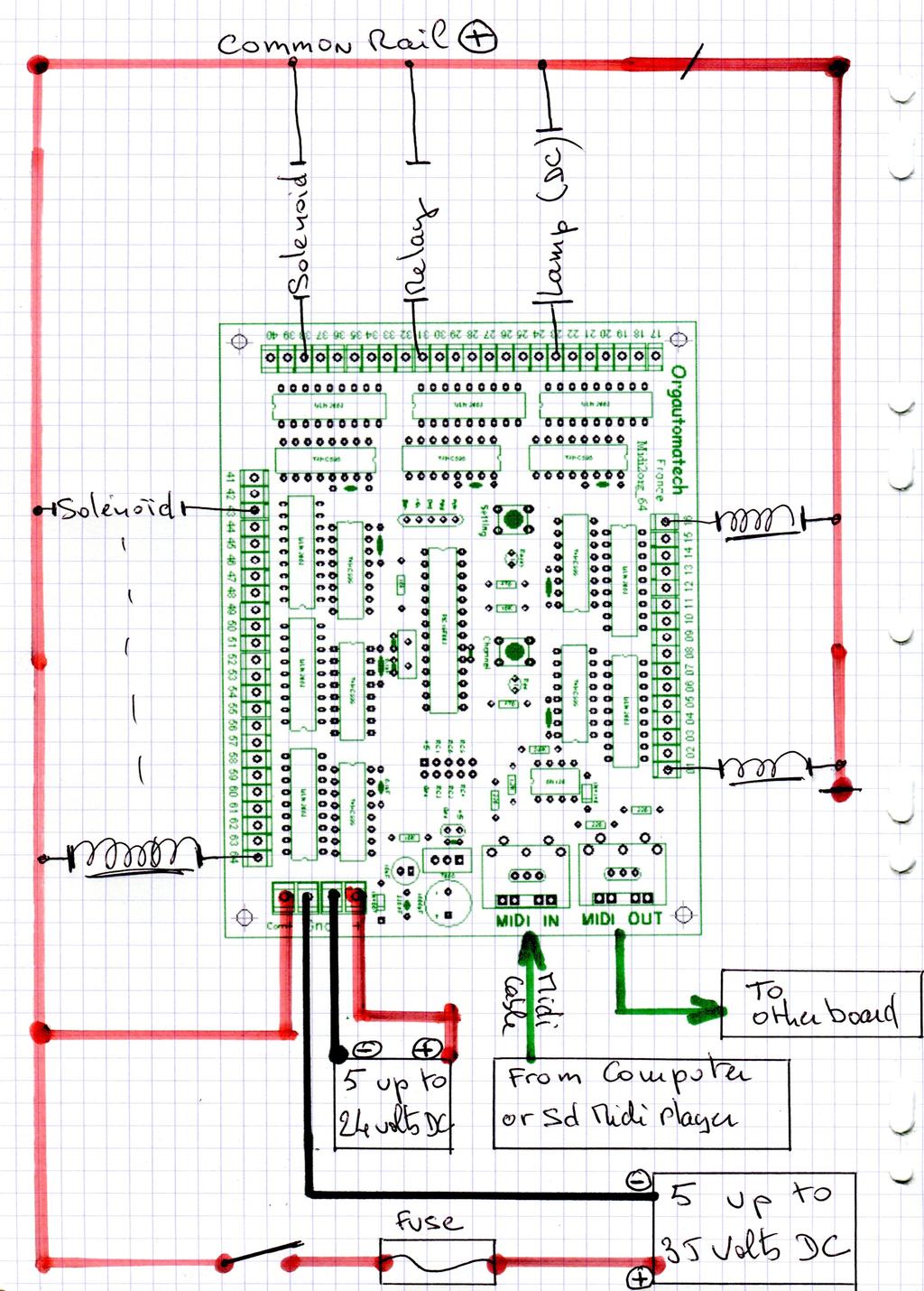
4 Electrical wiring There are 2 different voltage requirements on the board: The logic part, and the solenoid power. The logic part needs a power supply that gives between 8 and 24 volts DC. A small phone charger (8-12 volt, 100 ma) will work fine. Connect the + (usually the red one) to the + connector on the board and the to Gnd. There is protection against polarity reversal, don't worry! The board can deliver up to 35 volts to the solenoids. That's the limit of the ULN2803. You'll need to calculate the power requirement of each solenoid, and the number of notes you want to play simultaneously. Music is not necessarily made more beautiful just because there are many notes all at once. Even 10 notes playing at once is a very large number! A laptop power supply giving perhaps 6 amps or so is usually perfect. If you plan to power your instrument with less than 18 volts, (perhaps with a battery), then there is no need to have a second power supply for the logic part simply connect the terminal marked + with com+ by means of a small wire. There is no need to connect together the two terminals as these are already connected on the board. Please note than a continuously filtered current must drive the solenoids. One wire from each solenoid is connected together, and to the power + (plus). The other wire from each solenoid is connected to the corresponding output on the board. Yes, for the solenoids, the + (plus) is the common wire, not the gnd! I advice you to put a switch and a fuse on the solenoids + line. The switch is important if you don't have a special supply for board logic part. It allows to start the logic first and then the coils, which I highly recommend. You will need a 2.5 mm screwdriver for the terminal blocks. If something is not clear, please let me know: orgautomatix@orange,fr
5

6 MIDI wiring Connect a DIN 5 pin cable from your computer s (or SD reader) MIDI out socket and the Midi2Org MIDI IN socket. If you have another board or another Midi instrument that you want to play also, you can link the Midi2Org MIDI OUT to the MIDI IN of this other instrument. Please note that you should not connect the Midi2Org MIDI OUT to your computer or midi player s MIDI IN. This would cause problems, especially if your sequencer midi thru is on: an undesirable feedback loop would result! Midi channel setting The board responds to only one channel at a time. I did this because there is no good reason to have many channels on the same board. It s better to have as many boards as needed: one for each instrument or one for each register on large organs. The MIDI channel can be set easily, without changing anything else, and without a computer, directly on the board. This is very useful on stage when you want to play with others instruments. To verify or check the board s currently set MIDI channel: push the «channel» button once and count the number of red LED flashes. That number is the MIDI channel. To set the MIDI channel: 1. Push the setting button the green led switches off. While holding it down, press the channel button as many times as the channel you want, for example once for channel 1, twice for channel 2, etc. Don't be to quick. Each press must last at least ½ second. 2. When it's done, release the setting button. The green led switches on again. The new channel is recorded. 3. You can verify your setting by pushing the channel button and count the number of red LED flashes This procedure is needed only once. The board stores the midi channel in memory even when it is switched off. With 2012 Orgautomatech boards, channel can be changed by Orgautomatech freeware Parametor.

7 Notes mapping Midi2Org_64 can play 64 of the 128 notes of standard Midi. Unless you have asked for a special programming, the default factory mapping is midi numbers 48 to 111. If this doesn't suit your needs, you will need to remap the outputs. You'll need to do this only once. The board will store the notes in memory even when switched off. Classic procedure: 1. Link your computer or SD player Midilector out to the Midi2Org Midi in. Do not plug anything in the board Midi Out socket. 2. Prepare the logic power on the connector, but don't plug it in yet 3. Push the setting button and while holding it down, switch on the board. 4. Then release the button. The green led should be off. 5. Now send the 64 notes you want, starting with the one you want on the output #1. You can do this with a Midi keyboard, but it s easier with a midi file that you have prepared in advance. The notes will be stored in the order you send them. They can be chromatic or not. They will be registered with they channel. If you want to play with only one channel (I advise this solution)all the notes on the same channel<; Please ensure the sending midi channel is the one to which the board is set to receive. Each new note must start at least 10 milliseconds after end of the preceding note. You could use the sample files I ve put on my web page and modify each note as needed. As you send each note, the red led flashes. Even if you don't need 64 outputs you must send 64 notes. Please do not repeat any. After the 64th note has been sent, the red led switches off and the green one switches on. The board is ready to work!
8 Simplified procedure with Parametor (Orgautomatech freeware) 1. Link your computer out to the Midi2Org Midi in. Do not plug anything in the board Midi Out socket. 2. Switch on the board (logic part) 3.In the software Parametor, fill the boxes with the notes you want regarding of exit numbers. 4. select "64 outputs" and "setting" 5. Press "Send " The green LED on the card will shut down, the red LED will light up briefly, then the green LED is on again, it's done. All in less than a second! You can then check that everything works well, either in sequence (remember to select "test"), or by individual note by pressing the button corresponding to the output you want to test. One click plays the note, a second click stop it. You can thus check each note on your instrument and even tune it. For detail see also the Parametor user manual. Functionning If you have a separate supply for board logic part, switch it on first, and then switch on the solenoids. A few tenths of second after switching on the board, the green LED lights signifying that the board is ready to work. Midi2Org works on only one channel at a time, but sends via MIDI OUT everything that comes in via MIDI IN except sensing messages. So you can connect another board (daisy chain) or MIDI device. When it receives a note on the right channel but out of range (too low or too high) the red LED flashes. If you push one or other of the buttons during midi messages reception, this closes any open outputs and thus fixes a lost note-off. For safety, the maximum number of simultaneous notes possible is set to 15, which is enormous! This maximum can be changed, or even suppressed very easily, with Parametor software. For detail see also the Parametor user manual. Solenoid test procedure Switch off the board. Push the channel button and hold it while switching on the board. Then release the button. The board switches on each output for ¼ second one by one in sequence. By listening to the organ you can verify if all the notes are working. After all the notes have been played, the green led lights and the board is ready to receive midi commands.
9 Please note than, if your computer is on, you can make this test with Parametor. Security The maximum number of notes playing at once for all the board is 15. This is the factory setting, you can change it with Parametor software. The maximum number of notes playing at once on each 8 output group is: 4. Thius is the factory setting, you can change this number with Parametor. Impulse mode Midi2Org 32 and 64 can work in impulse mode, for xylophon, metalophon or some other percussion. In that mode, whatever the length of midi note, the corresponding output will play the length you have set up. The length can be fixed or dependent on velocity. You'll have to make test to find the best ratio. You can also set a security length, from 1 up to 60 seconds. Guarantee The Midi2Org_64 as all the Orgautomatech boards has a one-year guaranty against manufacturing fault. Each board is tested before shipping. I advice you to try it with its factory settings before changing the note mapping. You can test it with an electronic piano or a synthesizer with Midi out socket. Trouble shooting: If there seems to be a problem, please check a few things before sending back the board: The green LED doesn't light after switching on the board: Check the power polarity If you are using 2 power supplies (logic and solenoids) try switching on the logic power supply first. The green LED lights, but no output seems to work when sending a midi note: Is the midi cable connected to the board s MIDI IN and in the computer s MIDI out? Don't laugh, this happens also to me...
10 The MIDI OUT is used to connect another board or other midi instrument. It must not be connected to the MIDI IN of the computer! Is the board midi receive channel the same as the channel being sent? If the red led lights continuously your note mapping is not correct. An output seems to not work: Check your note mapping. In the file you send for auto-learning, each note must be at least 20 milliseconds after the preceding one. If an output stops working suddenly, suspect a problem with a ULN2803. ULNs are not fragile, but they cannot survive a short circuit. They are on dip sockets and so are very easily changed. If you have not got a special extractor, you can use a small screwdriver like a lever, alternately either side, very gently please. Be careful. Do not bend a pin when inserting the replacement. Before changing a ULN, check the solenoid! If there was a big problem with solenoid and the output still doesn't work even after changing the ULN, something else is damaged. Please contact me. Note that solenoids must be driven by filtered CC. Unfiltered power supplies can affect the functioning of the board. Tips & tricks for midi files On the Internet many midi files can be found, but they do not correspond necessarily to the range of your instrument, and furthermore, they have passed through the hands of many people, more or less expert, before you get them. Often they are very crowded with many midi messages as a result of numerous edits. I don t advise you to use them "as is ". It is better to take some time to edit them. It s pointless for example to have multiple tracks on 16 channels if you have only a single Midi2Org board. It would only slow down transmission. The MIDI standard is a "serial" connection, which means that every message is sent one after another on the same thread. There is no point in including messages for pitch bend etc. These and many other messages just add congestion and slow down the system. The first thing to be done with a new midi file is to clean it of all you do not need. Keep only the notes and possibly sustain if the card was programmed for a piano (on request for Midi2Og). If you are using Cubase, the function "erase everything except note" is very useful for this. I think that Cakewalk should have such a function too. After working for more than 20 years with MIDI, particularly on stage, I can tell you that this is very important and will save you many problems, lost notes, and other issues.
11 Have fun! Christian Blanchard Orgautomatech Christian Blanchard 113 rue Champommier Niort FRANCE 33(0) N Siret Update on 09/23/13
Midi2Org_16. An electronic board for automating a musical instrument. User Manual
 Midi2Org_16 An electronic board for automating a musical instrument User Manual Orgautomatech Christian Blanchard 113 rue Champommier 79000 Niort FRANCE 33(0)9 63 45 61 45 chris@orgautomatech.fr N Siret
MIDILECTOR / MIDILECTOR-R
 MIDILECTOR / MIDILECTOR-R Midi file reader on SD card User manual Orgautomatech Christian Blanchard 113 rue Champommier 79000 Niort FRANCE 33(0)9 63 41 45 chris@orgautomatech.fr SIRET 399 479 138 00022
AUDIO AMPLIFIER PROJECT
 Intro to Electronics 110 - Audio Amplifier Project AUDIO AMPLIFIER PROJECT In this project, you will learn how to master a device by studying all the parts and building it with a partner. Our test subject:
Register FAQ Calendar Today's Posts Search
 Custom Search Highly Liquid Forum > Current Products > UMR2 Yamaha VSS-30 MIDI Retrofit Guide User Name User Name Password Remember Me? Log in Register FAQ Calendar Today's Posts Search Page 1 of 2 1 2
MultiJAMMA Switchboard Installation and User s Manual
 MultiJAMMA Switchboard Installation and User s Manual 2000, Clay Cowgill Revision 1.0 Notice Regarding this Kit Warning! Although this kit has been tested and the techniques used will not directly cause
Instruction Manual for BE-SP3 Circuit. 10/21/07
 Page 1 of 54 Instruction Manual for BE-SP3 Circuit. 10/21/07 Page 1 Index: Page 2 BE-SP3 Circuit Specifications. Page 3-4 Intro to the BE-SP3. Page 5 Basics of serial to parallel. Page 6-7 ASCII Code.
Register FAQ Calendar Today's Posts Search
 Custom Search Highly Liquid Forum > Current Products > UMR2 Casio SK-5 MIDI Retrofit Guide User Name User Name Password Remember Me? Log in Register FAQ Calendar Today's Posts Search Page 1 of 2 1 2 >
Model IMP-22G2,H Low Cost Slave Clock Impulser Converts your slave clock to a working timepiece without modifying its original mechanism.
 Model IMP-22G2,H Low Cost Slave Clock Impulser Converts your slave clock to a working timepiece without modifying its original mechanism. The PIEXX IMP-22G2, H allows you to put your slave clock back into
SUNRISE MEDICAL EDUCATION DEPARTMENT INFO. VR2 Codes Display and Code description
 VR2 Codes Display and Code description NOTE: A Complete Description Taken from the official PG Drives Engineering Manual is described on the next 3 pages TRIP CODE Details from Page listing Trip Code 1-1
SETUP GUIDE INSTALLATION HANDBOOK. For Integrators, Installers and Administrators. Everything on how to get Kisi up and running. getkisi.
 SETUP GUIDE INSTALLATION HANDBOOK For Integrators, Installers and Administrators Everything on how to get Kisi up and running getkisi.com 1 TABLE OF CONTENT 13 14 INSTALLING KISI AS A STAND-ALONE SYSTEM
PC170 Control Box USER MANUAL 24V DC GEAR MOTOR FOR RESIDENTIAL
 PC170 Control Box 24V DC GEAR MOTOR FOR RESIDENTIAL USER MANUAL INDEX 1. CONTROL BOX 2. SETTING 2.1 SW1 DIP SWITCH SETTING 2.1.1 SLOWDOWN ADJUSTMENT (DIP 1. SLOW) 2.1.2 OVER-CURRENT ADJUSTMENT (DIP 2.OVER
Blue Point Engineering
 Blue Point Engineering Board - Pro Module (E) Instruction Pointing the Way to Solutions! Controller I Version 2.1 The Board Pro E Module provides the following features: Up to 4 minutes recording time
TEAM DIGITAL. DCCBreak DCC Circuit Breaker
 TEAM DIGITAL DCCBreak DCC Circuit Breaker Improving the world of DCC > Short and over current protection > Adjustable shutdown current level > Adjustable turn on delay > 4 amp continuous operation > Very
Worlde TUNA MINI MIDI Controller User s Manual
 HANGZHOU WORLDE DIGITAL PIANO CO.,LTD WEBSITE: WWW.WORLDE.COM.CN EMAIL:SALES@WORLDE.COM.CN TEL:86 571 88730848 Worlde TUNA MINI MIDI Controller User s Manual -1- Contents 1. INTRODUCTION... 3 2. FEATURES...
PM4 INSTRUCTIONS. PM4 WIRING (See Tables 1 & 2 and Wiring Examples)
") INSTRUCTIONS The can control 4 independent power sub-districts that can each be set up as either a "Short Circuit Manager" (default) or an "Auto-Reversing Controller." A separate booster can power each
INSTRUCTIONS The can control 4 independent power sub-districts that can each be set up as either a "Short Circuit Manager" (default) or an "Auto-Reversing Controller." A separate booster can power each
Assembly Instructions (8/14/2014) Your kit should contain the following items. If you find a part missing, please contact NeoLoch for a replacement.
 Your kit should contain the following items. If you find a part missing, please contact NeoLoch for a replacement.") NeoLoch NLT-28P-LCD-5S Assembly Instructions (8/14/2014) Your kit should contain the following items. If you find a part missing, please contact NeoLoch for a replacement. Kit contents: 1 Printed circuit
NeoLoch NLT-28P-LCD-5S Assembly Instructions (8/14/2014) Your kit should contain the following items. If you find a part missing, please contact NeoLoch for a replacement. Kit contents: 1 Printed circuit
Register FAQ Calendar Today's Posts Search
 Custom Search Highly Liquid Forum > Current Products > UMR2 Casio SK-1 MIDI Retrofit Guide User Name User Name Password Remember Me? Log in Register FAQ Calendar Today's Posts Search Page 1 of 3 1 2 3
Arduino 05: Digital I/O. Jeffrey A. Meunier University of Connecticut
 Arduino 05: Digital I/O Jeffrey A. Meunier jeffm@engr.uconn.edu University of Connecticut About: How to use this document I designed this tutorial to be tall and narrow so that you can read it on one side
Set-up and Use of your Wilson F/X Launch System
 WILSON F/X W F/X WIRELESS Wilson F/X Digital Launch Control Systems 903 East 6th Street, Sterling, IL 61081 www.wilsonfx.com Brad, the Rocket Rev., Wilson rocketrev@wilsonfx.com Tripoli #1630, L-3 NAR
Contents. Please read and remember the following warnings before using the RELAYplate:
 Contents 1 Warnings o 1.1 What is a Relay? o 1.2 Basic Features of the RELAYplate o 1.3 Attaching a Load to the RELAYplate o 1.4 The RELAYplate Command Set 1.4.1 RELAY Control Functions 1.4.2 LED Control
How to add a chip socket into your chipable ECU
 How to add a chip socket into your chipable ECU 1 / 7 In the tuning world if you decide that you would like to keep the stock ECU and just adjust the maps contained within then this is the guide for you.
PEDSCAN rev. C. standalone micro MIDI controller USER MANUAL
 PEDSCAN rev. C standalone micro MIDI controller USER MANUAL www.midi-hardware.com Roman Sowa 2016 1 Overview This little board is standalone controller for 32 keys and 1 potentiometer or external voltage
Q170 MIDI Gates. Q170 MIDI Gates Specifications. Aug 23, 2018
 Aug 23, 2018 The MIDI Gates module produces gate signals from a stream of MIDI messages, either from a keyboard, a DAW or any MIDI source. Each of the 8 outputs can be programmed for one or more MIDI note
User Manual for the Devil Fish MIDI In system V1.0.4
 User Manual for the Devil Fish MIDI In system V1.0.4 Robin Whittle 7 February 2016 www.firstpr.com.au/rwi/dfish/ (There are separate manuals for the V1.0.0 to V1.0.3 MIDI In systems and for the MIDI In
1/Build a Mintronics: MintDuino
 1/Build a Mintronics: The is perfect for anyone interested in learning (or teaching) the fundamentals of how micro controllers work. It will have you building your own micro controller from scratch on
Cobra Dimmer Master DMX Controller User Manual
 Cobra Dimmer Master DMX Controller User Manual User Manual Dimmer Master Dear Customer, Thank you for purchasing the Dimmer Master DMX controller. With decades of experience in design and production, we
Note. The above image and many others are courtesy of - this is a wonderful resource for designing circuits.
 Robotics and Electronics Unit 2. Arduino Objectives. Students will understand the basic characteristics of an Arduino Uno microcontroller. understand the basic structure of an Arduino program. know how
Torque Control Verifier
 Torque Control Verifier Instruction Manual Revision 1.2 September 2002 Please Read and Understand Instructions Before Attempting Installation Torque Control Verifier Contents: Quick Start Introduction
CV.OCD USER MANUAL. CV.OCD has four assignable continuous analog CV outputs and twelve assignable gate/trigger outputs. MIDI-TO-CV
 six4pix.com/cvocd CV.OCD USER MANUAL Introduction CV.OCD is a device which converts MIDI signals to the Control Voltage (CV) and Trigger/Gate signals which are used to control traditional analog synthesizers.
Written by Jered Flickinger Copyright 2013 Future Retro
 Written by Jered Flickinger Copyright 2013 Future Retro www.future-retro.com TABLE OF CONTENTS 1 INTRODUCTION - Overview - Precautions - Disclaimer - Warranty 2 CONNECTIONS - MIDI In - MIDI Thru - MIDI
Manual Main PCB Small-MIDI 4
 Index PARTLIST MAIN PCB... 2 INTRODUCTION... 3 GENERAL... 3 THE CIRCUIT... 3 ASSEMBLY KIT... 4 ASSEMBLY OF THE PCB... 4 An important tip...... 4 ASSEMBLY... 4 THE CONNECTORS... 4 Power supply J1... 4 IDC
Physics 120/220 Lab Equipment, Hints & Tips
 Physics 120/220 Lab Equipment, Hints & Tips Solderless Breadboard... 2 Power supply... 4 Multimeters... 5 Function generator... 5 Oscilloscope... 6 10X probe... 7 Resistor color code... 7 Components...
Basic Interface Techniques for the CRD155B
 Basic Interface Techniques for the CRD155B April 2001, ver. 1.10 Application Note 101 Introduction This application note contains basic information about interfacing external circuitry to computer I/O
XP: Backup Your Important Files for Safety
 XP: Backup Your Important Files for Safety X 380 / 1 Protect Your Personal Files Against Accidental Loss with XP s Backup Wizard Your computer contains a great many important files, but when it comes to
TC-7530DC with BMI-10
 TC-7530DC with BMI-10 Bushmaster MKI Instruction Manual Stereo Audio Digital-to-Analogue Converter Front Panel Overview The TC-7530DC Bushmaster is a reference-quality digital-to-analogue audio converter
Quicksilver 606 TR-606 CPU Upgrade
 Quicksilver 606 TR-606 CPU Upgrade D650C 128 Installation Guide Social Entropy Electronic Music Instruments TABLE OF CONTENTS WARNINGS... 1 OVERVIEW... 2 WHAT'S IN THE BOX... 3 OPENING THE TR-606 CASE...
University of Hull Department of Computer Science C4DI Interfacing with Arduinos
 Introduction Welcome to our Arduino hardware sessions. University of Hull Department of Computer Science C4DI Interfacing with Arduinos Vsn. 1.0 Rob Miles 2014 Please follow the instructions carefully.
How To Add Songs To Ipod Without Syncing >>>CLICK HERE<<<
 How To Add Songs To Ipod Without Syncing Whole Library Create a playlist, adding all the songs you want to put onto your ipod, then under the How to add music from ipod to itunes without clearing itunes
GALACTIC MOON 2CE. user manual. Abstract Design to Light 1996 Tel:
 GALACTIC MOON 2CE user manual Abstract Design to Light 1996 Tel:0116 278 8078 Galactic Moon 2CE Instruction Manual - Issue 1.1: Jan 96 (software v1.1) Written for Abstract Design to Light by Tim Mitchell,
REAL WORLD INTERFACES
 REAL WORLD INTERFACES Hardware and Software Design and Consulting rw@firstpr.com.au http://www.firstpr.com.au/rwi/ 5 December 2010 midi-808-rwi.pdf This is a copy of my documentation from July 1996 of
D115 The Fast Optimal Servo Amplifier For Brush, Brushless, Voice Coil Servo Motors
 D115 The Fast Optimal Servo Amplifier For Brush, Brushless, Voice Coil Servo Motors Ron Boe 5/15/2014 This user guide details the servo drives capabilities and physical interfaces. Users will be able to
January Bob Wright. 1 P age Bob Wright
 The upgrade is completed using the 401 control board and three Step1 driver boards supplied as a kit by Conqueror Design and Engineering Ltd. The kit includes all cable terminators for connections to the
PCR43304R, PCR43304RE 4-Channel, 433MHz Penta Receiver with Frequency Hopping
 PCR43304R, PCR43304RE 4-Channel, 433MHz Penta Receiver with Frequency Hopping Features Frequency hopping between 433.10 to 434.70MHz 12-way dipswitch or encrypted coding Momentary and latching modes are
TC-7533 Bushmaster Instruction Manual
 TC-7533 Bushmaster Instruction Manual Front Panel Stereo Audio Digital-to-Analogue Converter Overview The TC-7533 Bushmaster is a reference-quality digital-to-analogue audio converter featuring the latest
Digital Camera Controller
 SHUTTERBUG PRO Digital Camera Controller ShutterBug Pro is a tiny accessory that helps take digital or film camera snapshots. It is ideal for photographers that need to remotely snap photos or to time
MintySynth Software Manual v. 4.2
 MintySynth Software Manual v. 4.2 mintysynth.com info@mintysynth.com Contents Introduction I. Demo Song and Live Mode a. Demo Song b. Tempo c. Swing d. Waveform e. Duration f. Envelope II. III. IV. Photocell
DM-X Channel DMX Controller. Item ref: UK User Manual. Version 2.0
 DM-X10 192 Channel DMX Controller Item ref: 154.091UK User Manual Version 2.0 Caution: Please read this manual carefully before operating Damage caused by misuse is not covered by the warranty Contents
Wiring Instructions v3
 Wiring Instructions v3 Gatekeeper h4.1 Technical Support support@gymmastersoftware.com USA: 415 678 1270 Australia: 03 9111 0323 : 03 974 9169 Copyright 2017 Treshna Enterprises. All rights reserved. Table
DIGWDF Ren-W Universal Assembly Guide
 DIGWDF Ren-W Universal Assembly Guide Overview Before starting, be sure to read through the entire guide to familiarize yourself with the parts and parts locations. In many cases, you may not need to install
Warranty Disclaimer. Limitation of Liability
 Warranty Disclaimer Purchaser acknowledges that Top Cat Engineering L.L.C.has agreed to provide this kit for evaluation purposes only. Purchaser further acknowledges that Top Cat Engineering has no obligations
MIDIPLUS Co, Ltd.
 MIDIPLUS Co, Ltd. http://www.midiplus.com.tw Index Preface... 1 What s in the Box?... 1 AK490 Keyboard Overview:... 1 Chapter 1:Quick Start... 2 1.1 AK490 Overview... 2 1.1.1 Front panel Overview... 2
Part 2: Building the Controller Board
 v3.01, June 2018 1 Part 2: Building the Controller Board Congratulations for making it this far! The controller board uses smaller components than the wing boards, which believe it or not, means that everything
Make Kits and Casemods
 Make Kits and Casemods This weekend, you ll learn how to make a Minty Boost usb charger and a Daisy mp3 player. After you put these together you can put them into customized cases. I made my charger fit
Memory Keyer for the RockMite
 NØXAS PicoKeyer-RM Memory Keyer for the RockMite The PicoKeyer is a single chip, automatic iambic Morse code keyer with two message memories. Perfect for portable or QRP operation or for integrating into
ZX81 ULA Replacement. Installing the ULA
 ZX81 ULA Replacement The ZX81 ULA replacement is a plug in pin compatible clone of the original ZX81 ULA with a bit of an extra boost. Installing the ULA The replacement ula includes circuitry to directly
Delete Songs From Iphone Without Itunes Ios 5 >>>CLICK HERE<<<
 Delete Songs From Iphone Without Itunes Ios 5 Here's how to delete all music from iphone/ipad in ios 8. How to fix ios 8.4 GPS Issue on iphone/ipad for Apps Step 5 Tap on Music that all music that is on
Model HM-535 Power Supply Installation and Service Instructions
 Model HM-535 Power Supply Installation and Service Instructions 430-535 0104 2004 Heritage MedCall, Inc SENTRY INSTALLATION & SERVICE INSTRUCTIONS POWER SUPPLY UNIT Model HM-535 IMPORTANT SAFETY INSTRUCTIONS
H o t- S w a p Te r m i n a t o r
 SCSIView TM H o t- S w a p Te r m i n a t o r safely Remove or Install SCSI Devices With Power O N OWNERS MANUAL Table of Contents 1) How The Hot-Swap Terminator Works 1-2 2) Connecting The Hot-Swap Terminator
Memory Keyer for the RockMite
 NØXAS PicoKeyer-RM Memory Keyer for the RockMite The PicoKeyer is a single chip, automatic iambic Morse code keyer with two message memories. Perfect for portable or QRP operation or for integrating into
Repairing Williams C.P.U. boards. System 3, 4, 6 and 7. Test IC to check basic functionality of the cpu and driver 'out' of the pinball machine.
 Repairing Williams C.P.U. boards. System 3, 4, 6 and 7. Test IC to check basic functionality of the cpu and driver 'out' of the pinball machine. To my amazement I found almost no information about repairing
Zero2Go. User Manual (revision 1.03) Wide Input Range Power Supply for Your Raspberry Pi. Copyright 2017 UUGear s.r.o. All rights reserved.
 Wide Input Range Power Supply for Your Raspberry Pi. Copyright 2017 UUGear s.r.o. All rights reserved.") Zero2Go Wide Input Range Power Supply for Your Raspberry Pi User Manual (revision 1.03) Copyright 2017 UUGear s.r.o. All rights reserved. Table of Content Product Overview... 1 Product Details... 3 Package
Zero2Go Wide Input Range Power Supply for Your Raspberry Pi User Manual (revision 1.03) Copyright 2017 UUGear s.r.o. All rights reserved. Table of Content Product Overview... 1 Product Details... 3 Package
DLA. DMX512 Analyzer. DLA Users Manual SV2_00 B.lwp copyright ELM Video Technology, Inc.
 DLA DMX512 Analyzer DLA DLA-HH 1 Table Of Contents IMPORTANT SAFEGUARDS... 2 DLA OVERVIEW... 3 CONNECTION... 3 OPERATION... 3 HARDWARE SETUP... 4 DLA-HH (PORTABLE) LAYOUT... 4 CHASSIS LAYOUT... 4 DLA MENU
Modem Installation and Networking Instructions
 Modem Installation and Networking Instructions P/N 36870 Rev F Introduction The following instructions cover connecting a phone line to an incoming phone source, installing a modem, and setting up a network
6222 Two Door Module Technical Operations Manual
 6222 Two Door Module Technical Operations Manual TABLE OF CONTENTS Specifications...3 Overview...4 Operations...5 Custom Access Mode...5 Standard Access Mode...5 Offline Access Mode...5 Offline Memory...5
What are output transducers An output transducer will convert electrical signals passed to it by the process into another form of energy.
 What are output transducers An output transducer will convert electrical signals passed to it by the process into another form of energy. ACTIVITY Can you find the symbols of the output components listed
PCR43304R, PCR43304RE 4-Channel, 433MHz Penta Receiver with Frequency Hopping
 PCR43304R, PCR43304RE 4-Channel, 433MHz Penta Receiver with Frequency Hopping Features Frequency hopping between 433.10 to 434.70MHz 12-way dipswitch or encrypted coding Momentary and latching modes are
QuNexus CV Manual. QuNexus Version 1.0 May, 2013
 QuNexus CV Manual QuNexus Version 1.0 May, 2013 Connect QuNexus to Synthesizers or other CV devices: The images to the right below show QuNexus connected to a CV device. There are 3 different ways to set
Using Midi with 7Pad. 7Pad Midi IN and Out with USB cable. Tutorial Topics
 Using Midi with 7Pad Tutorial Topics Using Midi with 7Pad...1 7Pad Midi IN and Out with USB cable...1 Midi Input with USB :...3 Midi clock input and Ableton Link...4 7Pad output midi channels :...5 7PadMidi
C11G- MULTIFUNTCION CNC BOARD Rev. 8.2
 C11G- MULTIFUNTCION CNC BOARD Rev. 8.2 User manual Rev. 2 1. Overview This card has been designed to provide a flexible interface and functions to your computer projects, by using the parallel port control
User Guide for the Mobius Mini ActionCam
 Instruction Manual Mobius Min... 1 User Guide for the Mobius Mini ActionCam Description The above picture shows the arrangement of the user operating features. This manual does not cover replacing the
mp3 bbox 12-24V INSTALLATION GUIDE 4.0 REALITY SYS bbox 12-24V V4.0 Installation 1
 mp3 bbox 12-24V 4.0 REALITY SYS bbox 12-24V V4.0 Installation 1 Wiring First, connect the speakers to terminals 3-4 for left channel and 5-6 for right channel. You can use several loudspeakers in parallel
Professional Entertainment Technology. imove 50SR. Innovation, Quality, Performance 21-
 Innovation, Quality, Performance 21- imove 50SR User Guide Professional Entertainment Technology EC Declaration of Conformity We declare that our products (lighting equipments) comply with the following
PLUS+1 GUIDE Software. JS6000 PWM Service Tool User Manual
 PLUS+1 GUIDE Software JS6000 PWM Service Tool TEMP 1 6 1 6 12 7 12 7 About this Manual Organization and Headings To help you quickly find information in this manual, the material is divided into sections,
Grace Digital Mondo LCD Replacement & Part #s
 Grace Digital Mondo LCD Replacement & Part #s How to remove the Display Assembly also - Part Numbers. Written By: Seby ifixit CC BY-NC-SA www.ifixit.com Page 1 of 9 INTRODUCTION This is to replace an LCD
Industrial relay system RIFLINE complete
 Industrial relay system RIFLINE complete Easy handling RIFLINE complete relay system You can carry out all standard relay applications using the RIFLINE complete industrial relay system. It doesn't matter
OpenSprinkler v2.1u Build Instructions
 OpenSprinkler v2.1u Build Instructions (Note: all images below are 'clickable', in order for you to see the full-resolution details. ) Part 0: Parts Check Part 1: Soldering Part 2: Testing Part 3: Enclosure
INSTALLATION AND OPERATING INSTRUCTIONS DSST SYSTEM
 INSTALLATION AND OPERATING INSTRUCTIONS DSST SYSTEM PROPORTIONAL and NON-PROPORTIONAL TOGGLE SWITCH RADIO REMOTE CONTROL SYSTEM MODEL FHSTP/DSSTP SERIES FHST/DSST SYSTEM DESCRIPTION The DSST Wireless Control
MPS 150/190 User Guide
 MPS 150/190 User Guide FOR Motorized Public Speaking, 55 Walnut Street, Norwood, NJ 07648 Tel 201-767-6733 * email: info@telescript.com Website: www.telescript.com - 1 - MPS 150/190 Mechanical MPS Glass
OpenSprinkler v2.2u Build Instructions
 OpenSprinkler v2.2u Build Instructions (Note: all images below are 'clickable', in order for you to see the full-resolution details. ) Part 0: Parts Check Part 1: Soldering Part 2: Testing Part 3: Enclosure
DS64. All Scales Track Voltage Up to 22 Volts
 Digitrax Complete Train Control Run Your Trains, Not Your Track! DS64 Stationary Decoder for use with 4 slow motion, solenoid, or bi-polar turnout machines All Scales Track Voltage Up to 22 Volts Features
Model BB9 RS-232 Multi-Drop Box. Operating Bulletin. Innovative Flow and Pressure Solutions. Standard 8 pin Mini-DIN Connector
 Operating Bulletin Standard 8 pin Mini-DIN Connector Model BB9 RS-232 Multi-Drop Box Innovative Flow and Pressure Solutions 6 pin Locking Industrial Connector 1 12/15/2011 Rev.1 DOC-BB9MAN-RS232 2 Alicat
CUSTOM FOOTSWITCH Z-9. Operator s Manual. Please, first read this manual carefully!
 CUSTOM FOOTSWITCH Z-9 Operator s Manual Please, first read this manual carefully! Table of Contents Introduction Features and Functionality at a Glance page: 3 3 Control Panel Features: Channel 1 or Patch
MASTERMIND GT. User s Manual RJM MUSIC TECHNOLOGY, INC.
 MASTERMIND GT TM User s Manual RJM MUSIC TECHNOLOGY, INC. MASTERMIND GT TM User s Manual Version 4.1 9/11/2018 RJM Music Technology, Inc. 2525 Pioneer Ave. Suite 1 Vista, CA 92081 +1-760-597-9450 email:
HEX Par 9 MKII. Exterior Fixture User Manual. Order code: LEDJ226
 HEX Par 9 MKII Exterior Fixture User Manual Order code: LEDJ226 Safety advice WARNING FOR YOUR OWN SAFETY, PLEASE READ THIS USER MANUAL CARE- FULLY BEFORE YOUR INITIAL START-UP! Before your initial start-up,
2010, 2013 Azatrax.com MRD2-S USB with Switch Control installation instructions pg. 1 of 6
 Installation Instructions Azatrax Dual Infrared Model Train Detector MRD2-S, USB with Switch Control What it is: The MRD2-S is a two-channel model train detector. It can detect model trains at two different
2.2" TFT Display. Created by lady ada. Last updated on :19:15 PM UTC
 2.2" TFT Display Created by lady ada Last updated on 2017-12-22 11:19:15 PM UTC Guide Contents Guide Contents Overview Pinouts Assembly Arduino Wiring Arduino UNO or Compatible Wiring Wiring for Other
PCR43301RE 1-Channel, 433MHz Penta Receiver with Frequency Hopping
 PCR43301RE 1-Channel, 433MHz Penta Receiver with Frequency Hopping Features Frequency hopping between 433.10 to 434.70MHz 12-way dipswitch or encrypted coding Compatible with PentaFOB and PentaCODE remotes
C23- DUAL PORT MULTIFUNCTION CNC BOARD Rev. 3.1
 C23- DUAL PORT MULTIFUNCTION CNC BOARD Rev. 3.1 User manual Rev. 2 1. Overview This card has been designed to provide a flexible interface and functions to computer CNC projects, by using the parallel
The Solution. Multi-Input Module IMPORTANT: READ AND UNDERSTAND ALL INSTRUCTIONS BEFORE BEGINNING INSTALLATION
 The Solution Multi-Input Module INSTALLATION INSTRUCTIONS Model: MIM-62 IMPORTANT: READ AND UNDERSTAND ALL INSTRUCTIONS BEFORE BEGINNING INSTALLATION MIM-62 connects up to 6 monitored entrapment protection
HauntMaven.com - Wolfstone's Haunted Halloween Site.
 HauntMaven.com - Wolfstone's Haunted Halloween Site http://wolfstone.halloweenhost.com/remotecontrol/dmxint_dmxintro.html DMX Control DMX 512 is an industrial strength protocol originally intended to control
TEAM DIGITAL. SRC162e Switch & Route Controller
 TEAM DIGITAL SRCe Switch & Route Controller Improving the world of DCC > DCC compatible accessory decoder > Control switches (turnouts) > Drive switch status LEDs > Drive Tortoise switch machines > configurable
Serial Data DIN Fiber Link System
 USER GUIDE RLH Industries, Inc. The leader in rugged fiber optic technology. U-120 2017A-0420 DIN Fiber Link System COMPACT, RUGGED & TEMPERATURE HARDENED Introduction The DIN Fiber Link system transports
Racegun Interface Program -RIP This section covers installation and use of the PC-software for the Racegun grip.
 Racegun Interface Program -RIP This section covers installation and use of the PC-software for the Racegun grip. This guide is for the RIP version 1.X please visit www.raceguns.dk for an update if you
CORE BASICS COMPETENCY EXAM README RICOH GROUP COMPANIES
 RICOH GROUP COMPANIES CORE BASICS COMPETENCY EXAM README It is the reader s responsibility when discussing the information contained within this document to maintain a level of confidentiality that is
OBDI Tune Kit Quick Start Guide
 OBDI Tune Kit Quick Start Guide Revision A Page 1 Table of Contents Introduction... 3 Contents... 3 Early ECM Kits:... 3 Late ECM Kits:... 3 Minimum PC Requirements... 3 Program Installation... 4 Registering
FAQ. Thump Series. What models are featured in the Thump Series?
 Thump Series http:///products/thump What models are featured in the Thump Series? The Thump Series will consist of four powered loudspeakers and one powered subwoofer: Thump12A 1300W 12" Powered Loudspeaker
Perform general SC916 electrical testing. With external power removed, step on one or both of the pedal arms
 Perform general SC916 electrical testing With external power removed, step on one or both of the pedal arms the console turn on? battery in a charged state? Using external power supply, charge battery
MIDI SWITCHER Z-11. Operator s Manual. Please, first read this manual carefully!
 MIDI ER Z-11 Operator s Manual Please, first read this manual carefully! The MIDI Switcher Z-11 was designed for accessing specific switchable functions of amps (e.g. "Ritchie Blackmore Signature", "Thunder
INSTRUCTIONS FOR MIDI INTERFACE
 INSTRUCTIONS FOR MIDI INTERFACE MICROMOOG USING THE MIDI INTERFACE - - - When you turn on the synthesiser for the first time, you will be in omni-on mode for receive (all channels). When you select a receive
PCR43301RE ELSEMA. . and anywhere else you need a wireless signal to transmit a contact closure. Description
 PCR43301RE 1-Channel, 433MHz Penta Receiver with Frequency Hopping Features Frequency hopping between 433.10 to 434.70MHz 12-way dipswitch or encrypted coding Compatible with PentaFOB and PentaCODE remotes