Amphenol Amphenol-Tuchel Electronics GmbH. heavy mate. Heavy Duty Connectors.
|
|
|
- Kristopher Moody
- 6 years ago
- Views:
Transcription


1 Amphenol Amphenol-Tuchel Electronics GmbH heavy mate Heavy Duty Connectors

2 Note from the CEO Ladies and Gentlemen, For over 75 years Amphenol has enjoyed success as the interconnection technology provider of choice to industry-leading companies around the world. One of our key strategic areas of focus has been and is the Industrial market. Our organization works with leading manufacturers across a wide range of applications - including Energy Generation & Distribution, Transportation, Heavy Equipment, Factory Automation, Wireless Outdoor, ChipCard Readers - enabling smarter, faster and better technologies to connect products to customer solutions. The Industrial market footprint of Amphenol covers over facilities in more than 12 different European countries and more than 30 countries worldwide. Our successful expansion into new regions as well as new industrial applications is a direct reflection of our agile, entrepreneurial management team and our unwavering commitment to execute Amphenol s strategies for the benefit of our customers, shareholders and employees. Thank you for partnering with Amphenol. Our entire organization is at your service. R. Adam Norwitt President and CEO, Amphenol Corporation 2

3 Make use of the best Use our global resources Think global, act local! Independently from where you are in Europe, we offer you our global expertise and great variety of products and technologies. And in comfort with your personal contact. Our numerous European offices are your access to our global resources. OUR OFFICES IN EUROPE AND WORLDWIDE FRANCE CHINA AUSTRALIA SOUTH AFRICA GERMANY KOREA MEXICO INDIA UNITED KINGDOM TAIWAN USA ITALY 3

4 4 SECURITY, RELIABILITY AND COMFORTABLE SERVICE FROM ONE SOURCE.
5 More time for important things: benefit from our service and diversity Enjoy security, reliability and comfortable service from one source. offers one of the most individual and most diversified service programmes in the market exclusively for industrial customers. Access all possibilities of the Amphenol group through your personal expert adviser. WIDE PRODUCT RANGE EXCLUSIVENESS AND FLEXIBILITY Take advantage of a choice of Amphenol products. Our broad product portfolio offers individual solutions from more than 85 member companies in the global Amphenol group. One face to the customer: every inquiry is handled on an individual service level by your personal key account service partner. This ensures maximum transparency and best-in-class flexibility in the whole process. QUALITY INDIVIDUAL SOLUTIONS Interconnect systems need reliability, speed and flawless data transmission. We continuously test and guarantee the required standard in our products and also in our personal services. Your project requires an individual solution that is not available offthe-shelf? As your think tank and discussion partner we provide engineering support and solution-oriented development for your tailor-made Amphenol product. SPEED AND AVAILABILITY GLOBAL KEY ACCOUNT SERVICE Smart and intelligent processes are the secret behind our service programme. Flexible planning and distribution, perfect logistics and highest availability are our key factors for best customer service. Our key account service is your individual entrance to global know-how, products and services. More than 85 Amphenol companies around the world offer an extensive range of technologies and products. We offer access to our worldwide resources through one individual contact person. 5


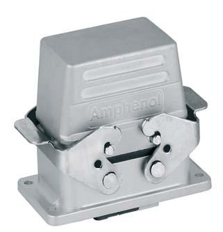
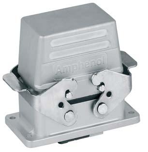
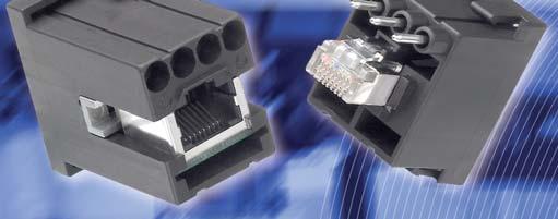
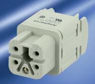
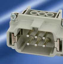
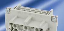
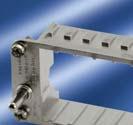
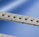
6 heavy mate is a Modular Metal Connector Line What is heavy mate? heavy mate is a modular connector line, consisting of: Hoods & Housings Inserts Contacts Why heavy mate? Connections in harsh industrial environment Robust design necessary High number of poles or different kinds of signals transmitted Very good EMC protection required Power and signal transmission outdoor Very safe locking system required 6


7 for Applications in Industrial Environments. Major product features Hybrid interconnections Good costs Voltage up to 1000V VDE, UL, CSA approvals Vibration proof High current Signal transmission High pole sizes IP65 to IP68 Corrosion resistance Robust What can heavy mate offer? Connectors for industrial applications indoor & outdoor A wide range of inserts for signal and power transmission A large variety in pole sizes from 3 up to 280 poles per connector Current ratings up to 250A per contacts and voltages up to 1000V A modular connector system to configure customized solutions 7


8 How to select a solution with series heavy mate. Theory Select an insert that meets your requirements. Choose the related contacts if not included in inserts. Choose related housings. Choose related cable gland. If you are interested in a cable assembly, please ask us. Practice 1 Requirements 250V 5A 60 contacts Termination: crimp Solution Check: Make a pre-selection on the overview page of the series, s. p. 10/11 Possible series: heavy mate D, DD and M Check: Details on the overview pages of the sub-series, see pages 22, 38, 126 All 3 variants are possible; Selection heavy mate D Check: Contact inserts on the detail page of the sub-series Selection: C146 10A Check: Contacts on the same double page Selection: VN Check: Housings via crosslink at contact inserts Selection: C146 21R Check: Gland bushing via crosslink at housings Selection: VN X 8

 1 x 20 contacts b) 2 x 10 contacts c) 1 x 10 contacts + 2 x 5 contacts d) 1 x 3 contacts + 1 x 5 contacts + 1 x 10 contacts")
 not possible due to voltage c) not possible due to current d) POSSIBLE Check: Choose matching contact, see detail page")

9 Practice 2 Requirements 3 x 400V; 50A; 6mm² wire gauge 8 x 250V; 8A; 1.5mm² wire gauge 5 x 400V; 15A; 4mm² wire gauge Solution Check: Make a pre-selection on the overview page of the series, see pages 10/11 Possible series: heavy mate M Check: How 16 contacts can be realized, see modules overview on page 130 Possible selection: a) 1 x 20 contacts b) 2 x 10 contacts c) 1 x 10 contacts + 2 x 5 contacts d) 1 x 3 contacts + 1 x 5 contacts + 1 x 10 contacts Check: Technical parameters / solution, see detail pages of the modules on page 138 Possible selection: a) not possible due to voltage b) not possible due to voltage c) not possible due to current d) POSSIBLE Check: Choose matching contact, see detail page of the modules on page 138 Possible selection: a) C146 A E8 VN C b) C146 A E8 VN C c) C146 A E8 VN C Check: Choose matching frame, see frames on page 136 Solution: C146 P G8 Check: Choose matching housing, see housings on page 184 Solution: C146 21R
10 Make your selection out of the heavy mate series! Series Characteristic A page 14 D page 22 DD page 38 E page 44 EE page 62 E /FE / KO page 68 F page 74 Voltage Current 250V 400V 500V 690V 830V 1000V 10A 16A 35A 80A 100A 200A Numbers of contacts Modules for x Termination Crimp Screw Tension spring Cross reference list see 10
11 HSE page 104 HvE page 108 K page 118 M page 126 Q page 168 Housings page 184 Accessories page 251 Series Characteristic Voltage 250V 400V 500V 690V 830V 1000V 10A 16A 35A 80A 100A 200A Current Modules for Numbers of contacts / 0 4 / 2 6 /36 4 / / Crimp Screw Termination Tension spring 11


12 The highlights of the series heavy mate. Contact technology Turned contacts, which correspond to the market standard. Turned female contacts of copper for higher current-carrying capacity specifically for the modular system heavy mate M. Radsok contact technology: These are laminated contacts with very low transition resistance, suitable for high current applications. Stamped contacts with high performance for semi-automatic processing at great cost savings. Selectively coated gold plating stamped contacts offer great savings. Housings Surface coatings available in two versions: Standard or High-End with a salt mist resistance up to 500 hours. Flexible cable entry in different positions possible on request. Tightness classes in IP65, IP67 or IP68! Robust metal levers in 1 and 2 lockinglever-system. Quality EMC solutions. 12


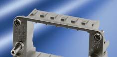
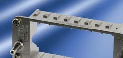
13 Modular system With the new series heavy mate F Amphenol offers a new modular system that is compatible with the market leader. With the series heavy mate M Amphenol offers a system with many benefits: More module slots in the connector. Large selection of contact-safe male contacts Stamped contacts and the Radsok contact technology Great cost savings potential 13


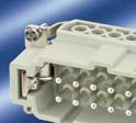
14 heavy mate A Rated voltage 250 / 400 V Rated current 14 A A Termination: screw Number of contacts: 3, 4, 10, 16, 32 14


15 heavy mate A Brief information Approvals, Testhouse Characteristics Approval-Number SEV 250 V, 10 A UL 600 V, 14 A E CSA 600 V, 10 A; 16 A; 20 A LR In general approvals refer to representative versions of the connector series. Extent and specification of tests upon request. 15
16 heavy mate A General information General information For series heavy mate A connectors may be engaged or disengaged when live but without electrical load. If these connectors are used as plug and socket device, the load shall be reduced to 10 % of the rated current. No standard for this series, but: Interchangeable with other makes a) contact insert to contact insert b) contact insert to housing 10,16 contacts First-to-mate last-to-break protective ground contact Low and high profile housing for heavy mate A series inserts for 10 and 16 contacts. Housings are designed according to DIN EN Range of housings Size A3/4 Size A10 Size A16 16
17 heavy mate A Characteristics contact inserts General Characteristics Standard Value Number of contacts 3/ Termination technique screw Wire gauge mm 2 Flammability UL 94 V-0 Electrical Characteristics Rated voltage IEC V 250 V Pollution degree IEC Installation (overvoltage) category IEC III Material group IEC III b Rated impulse withstand voltage IEC KV Current carrying capacity IEC see derating curves Rated current T amp = 40 C 18 A 16 A 14 A 14 A Contact resistance IEC m Ω Insulation resistance IEC Ω Climatical Characteristics Climatic category IEC / 100 / 21 Upper temperature IEC C Lower temperature IEC C Mechanical Characteristics IP-degree of protection pin insert 1) IEC unmated IP00 mated IP20 IP-degree of protection socket insert 1) IEC unmated IP20 mated IP20 Weight pin insert 13 g 48 g 68 g 136 g Weight socket insert 13 g 52 g 73 g 146 g Mechanical operation IEC mating cycles Materials Insert PA PBT PBT PBT Contacts Cu Zn (brass) Contact plating Ag (silver) IP-degree of protection on termination side of screw version IP10 17


18 heavy mate A Contact inserts Size A3/4 400 V/10 A Housings from page 188 Description Part Number Drawing Figure Contact insert 3 + Male insert for screw termination C146 10A Female insert for screw termination C146 10B Pin layout Male insert Female insert Description Part Number Drawing Figure Contact insert 4 + Male insert for screw termination C146 10A Female insert for screw termination C146 10B Pin layout Male insert Female insert Derating curves Curve Wire gauge a 1.5 mm 2 b 2.5 mm 2 18


19 heavy mate A Contact inserts 10 + Size A V/16 A Housings from page 190 Description Part Number Drawing Figure Contact insert 10 + Male insert for screw termination C146 10A Male insert with wire protection for screw termination Female insert for screw termination C146 10A C146 10B Female insert with wire protection for screw termination C146 10B Pin layout Assembly instruction Male insert Female insert Panel cut out (insert) Derating curves Curve Wire gauge a 1.5 mm 2 b 2.5 mm 2 19


 Derating curves Curve Wire gauge a")
20 heavy mate A Contact inserts 16 + Size A V/16 A Housings from page 192 Description Part Number Drawing Figure Contact insert 16 + Male insert for screw termination C146 10A Male insert with wire protection for screw termination Female insert for screw termination C146 10A C146 10B Female insert with wire protection for screw termination C146 10B Pin layout Assembly instruction Male insert Female insert Panel cut out (insert) Derating curves Curve Wire gauge a 1.5 mm 2 b 2.5 mm 2 20

 Male insert with wire protection for")
")
 C146 10B016 102 4 (1-16) + C146 10B016 104 4 (17-32)")
 Derating curves Curve Wire gauge a 1.5 mm 2 b 2.")
21 heavy mate A Contact inserts 2x16 + PE Size A V/16 A Housings from page 190 Description Part Number Drawing Figure Contact insert 32 + Male insert for screw termination C146 10A (1-16) + C146 10A (17-32) Male insert with wire protection for screw termination Female insert for screw termination Female insert with wire protection for screw termination C146 10A (1-16) + C146 10A (17-32) C146 10B (1-16) + C146 10B (17-32) C146 10B (1-16) + C146 10B (17-32) Pin layout Assembly instruction Male insert Female insert Panel cut out (insert) Derating curves Curve Wire gauge a 1.5 mm 2 b 2.5 mm 2 21


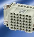
22 heavy mate D Rated voltage 250 V Rated current 10 A A Termination: crimp Number of contacts: 7, 15, 25, 40, 50, 64,


23 heavy mate D Brief information Approvals, Testhouse Characteristics Approval-Number SEV 250 V, 10 A UL 600 V, 14 A 600 V, 15 A (high current) E CSA 600 V, 10 A In general approvals refer to representative versions of the connector series. Extent and specification of tests upon request. 23
.")


 Interchangeable with all other products which are according to the standard.")
24 heavy mate D General information General information Contact inserts without crimp contacts, crimping tools see For contact inserts for turned contacts, guide pins and guide separate catalogue Tools. socket are recommended (see page 256). Contacts must be ordered separately, processing instructions By using contact inserts with two PE-connections without hoods, it see catalogue Tools. is necessary to connect the facing of each PE-connection. We recommend using the high profile housings / hoods for the If connectors are mounted in non conductive housings both heavy mate D inserts. protective earthing terminals shall be mounted. Connectors series heavy mate D may be engaged or disengaged when live but without electrical load. If these connectors are mated or unmated under load, the load shall be reduced to 10 % of the rated current. Standardised connectorsaccording to DIN EN (DIN 43652) Interchangeable with all other products which are according to the standard. a) Contact insert to contact insert 15, 25, 40, 64 way. b) Contact insert to housing 15, 25, 40, 64 way. High protection against mismating First-to-mate last-to-break protective ground contact Female inserts with funnel shaped contact entry avoids mismating with stamped contacts. Restricted entry Contact inserts for stamped contacts and for turned contacts Range of housings Size A3/4 Size A10 Size A16 Size E16 Size E24 Size E48 24
25 heavy mate D General information Modified contact arrangement for rated voltages of 400 V (15) 7 + (25) 11 + (40) 20 + (64) 32 + full load contact unoccupied Removal of contacts, front releas stamped male contacts all turned contacts stamped female contacts 25
26 heavy mate D Characteristics contact inserts General Characteristics Standard Value Number of contacts x25 Contact arrangement DIN EN (DIN 43652) Termination technique Max. wire diameter Flammability UL 94 V-0 crimp, wire wrap 4.1 mm x64 Electrical Characteristics Rated voltage 1) IEC V~ (400 V~ 2) ) (600 V UL / CSA 3) ) Pollution degree IEC Installation (overvoltage) category IEC III Material group IEC III b Rated impulse withstand voltage IEC kv Rated current IEC see derating curves Rated current T amp = 40 C 16 A 12 A 12 A 10 A 10 A 10 A 10 A Insulation resistance IEC Ω Climatical Characteristics Climatic category IEC /125/21 Upper temperature IEC C Lower temperature IEC C Mechanical Characteristics IP-degree of protection pin insert IEC unmated IP00 mated IP20 IP-degree of protection socket insert IEC unmated IP20 mated IP20 Weight pin insert 8 g 28 g 34 g 53 g 68 g 65 g 130 g Weight socket insert 8 g 30 g 38 g 64 g 76 g 82 g 164 g Mechanical operation IEC mating cycles Materials Insert IEC PBTP PC GV 4) Colour insert IEC grey 26 1) Restriction for 8 contacts in metal housing see page 27 2) Modified contact arrangement, see page 25 3) Label for CSA application see page 258 4) Polycarbonat-glas fibre filled


 Male insert Female insert Derating curves Stamped contacts")
 8/PE Turned contacts Curve Wire gauge a")
27 heavy mate D Contact inserts 7 +, 8 pol Size A3/4 250 V/10 A Housings from page 188 Description Part Number Drawing Figure Contact insert 7 +, 42 V~ in metal housings/250 V in thermoplastic housings (Please order contacts separately, see page 34) Male insert C146 10A for stamped crimp contacts Male insert for turned crimp contacts C146 10A Female insert for stamped crimp contacts C146 10B Female insert for turned crimp contacts C146 10B Pin layout Male insert 7+ Female insert Protective earthing contact preleading Description Part Number Drawing Figure Contact insert 8, 42 V~ in metal housings/250 V in thermoplastic housings (Please order contacts separately, see page 34) Male insert C146 10A for stamped crimp contacts Male insert for turned crimp contacts C146 10A Female insert for stamped crimp contacts C146 10B Female insert for turned crimp contacts C146 10B Pin layout (Note: For use up to 42 V~, the PE contact can be used as regular contact.) Male insert Female insert Derating curves Stamped contacts Curve Wire gauge a 0.5 mm 2 b 1.5 mm 2 & 2.5 mm 2 c 1.5 mm mm 2 (High current) 8/PE Turned contacts Curve Wire gauge a 0.5 mm 2 b 1.5 mm 2 c 2.5 mm 2 27
 Male insert C146 10A015 000 2 for stamped crimp contacts Male insert for turned crimp contacts C146 10A015")
 Male insert C146 10A015 060 2 for stamped crimp contacts Female insert for stamped")
 Turned contacts Curve Wire gauge a 0.5 mm 2 b 1.5 mm 2 c 2.5 mm 2 28")
28 heavy mate D Contact inserts 15 + Size A V/10 A Housings from page 190 Description Part Number Drawing Figure Contact insert 15 + (Please order contacts separately, see page 34) Male insert C146 10A for stamped crimp contacts Male insert for turned crimp contacts C146 10A Female insert for stamped crimp contacts C146 10B Female insert for turned crimp contacts C146 10B Contact insert 15 +, 2 x PE-termination (Please order contacts separately, see page 34) Male insert C146 10A for stamped crimp contacts Female insert for stamped crimp contacts C146 10B Pin layout Assembly instruction Male insert Female insert Panel cut out (insert) Derating curves Stamped contacts Curve Wire gauge a 0.5 mm 2 b 1.5 mm 2 c 2.5 mm 2 d 1.5 mm mm 2 (High current) Turned contacts Curve Wire gauge a 0.5 mm 2 b 1.5 mm 2 c 2.5 mm 2 28
 Male insert C146 10A025 000 2 for stamped crimp contacts Male insert for turned crimp contacts C146 10A025")
 Male insert C146 10A025 060 2 for stamped crimp contacts Female insert for stamped")
 Turned contacts Curve Wire gauge a 0.5 mm 2 b 1.5 mm 2 c 2.5 mm 2 29")
29 heavy mate D Contact inserts 25 + Size A V/10 A Housings from page 192 Description Part Number Drawing Figure Contact insert 25 + (Please order contacts separately, see page 34) Male insert C146 10A for stamped crimp contacts Male insert for turned crimp contacts C146 10A Female insert for stamped crimp contacts C146 10B Female insert for turned crimp contacts C146 10B Contact insert 25 +, 2 x PE-termination (Please order contacts separately, see page 34) Male insert C146 10A for stamped crimp contacts Female insert for stamped crimp contacts C146 10B Pin layout Assembly instruction Male insert Female insert Panel cut out (insert) Derating curves Stamped contacts Curve Wire gauge a 0.5 mm 2 b 1.5 mm 2 c 2.5 mm 2 d 1.5 mm mm 2 (High current) Turned contacts Curve Wire gauge a 0.5 mm 2 b 1.5 mm 2 c 2.5 mm 2 29
30 heavy mate D Contact inserts 40 + Size E V/10 A Housings from page 205 Description Part Number Drawing Figure Contact insert 40 + (Please order contacts separately, see page 34) Male insert C146 10A for stamped crimp contacts Male insert for turned crimp contacts C146 10A Female insert for stamped crimp contacts C146 10B Female insert for turned crimp contacts C146 10B Contact insert 40 +, 2 x PE-termination (Please order contacts separately, see page 34) Male insert C146 10A for stamped crimp contacts Female insert for stamped crimp contacts C146 10B Pin layout Assembly instruction Male insert Female insert Panel cut out (insert) Derating curves Stamped contacts Curve Wire gauge a 0.5 mm 2 b 1.5 mm 2 c 2.5 mm 2 d 1.5 mm 2 (High current) e 2.5 mm 2 (High current) Turned contacts Curve Wire gauge a 0.5 mm 2 b 1.5 mm 2 c 2.5 mm 2 30

 Male insert for stamped crimp")


 Turned contacts Curve Wire gauge")
31 heavy mate D Contact inserts 50 + Size A V/10 A Housings from page 194 Description Part Number Drawing Figure Contact insert 50 + (Please order contacts separately, see page 34) Male insert for stamped crimp contacts C146 10A C146 10A Male insert for turned crimp contacts Female insert for stamped crimp contacts Female insert for turned crimp contacts C146 10A C146 10A C146 10B C146 10B C146 10B C146 10B Pin layout Assembly instruction Male insert Female insert Panel cut out (insert) Derating curves Stamped contacts Curve Wire gauge a 0.5 mm 2 b 1.5 mm 2 c 2.5 mm 2 d 1.5 mm 2 (High current) e 2.5 mm 2 (High current) Turned contacts Curve Wire gauge a 0.5 mm 2 b 1.5 mm 2 c 2.5 mm 2 31
32 heavy mate D Contact inserts 64 + Size E V/10 A Housings from page 211 Description Part Number Drawing Figure Contact insert 64 + (Please order contacts separately, see page 34) Male insert C146 10A for stamped crimp contacts Male insert for turned crimp contacts C146 10A Female insert for stamped crimp contacts C146 10B Female insert for turned crimp contacts C146 10B Contact insert 64 +, 2 x PE-termination (Please order contacts separately, see page 34) Male insert C146 10A for stamped crimp contacts Female insert for stamped crimp contacts C146 10B Pin layout Assembly instruction Male insert Female insert Panel cut out (insert) Derating curves Stamped contacts Curve Wire gauge a 0.5 mm 2 b 1.5 mm 2 c 2.5 mm 2 d 1.5 mm 2 (High current) e 2.5 mm 2 (High current) Turned contacts Curve Wire gauge a 0.5 mm 2 b 1.5 mm 2 c 2.5 mm 2 32
33 heavy mate D Contact inserts Size E V/10 A Housings from page 217 Description Part Number Drawing Figure Contact insert (Please order contacts separately, see page 34) Male insert for stamped crimp contacts C146 10A C146 10A Male insert for turned crimp contacts Female insert for stamped crimp contacts Female insert for turned crimp contacts C146 10A C146 10A C146 10B C146 10B C146 10B C146 10B Pin layout Assembly instruction Male insert Female insert Panel cut out (insert) Derating curves Stamped contacts Curve Wire gauge a 0.5 mm 2 b 1.5 mm 2 c 2.5 mm 2 d 1.5 mm 2 (High current) e 2.5 mm 2 (High current) Turned contacts Curve Wire gauge a 0.5 mm 2 b 1.5 mm 2 c 2.5 mm 2 33
 0.14 0.25 0.5 0.5 1.0 1.5 1.5 2.")


34 heavy mate D Crimp technology Large range of wire gauges.n N N Gas-tight (coldwelding) Stamped crimp contacts with insulation crimp, to absorbe mechanical stress from the crimped connection Insulation grip Mechanical retention spring stop on female and male contact Female contact Male contact High current carrying capacity Example single contact Curve a: 2.5 mm 2 Standard contact. wire gauge Curve a: 2.5 mm2 High current contact, wire gauge 34
35 heavy mate D Characteristics crimp contacts Stamped crimp contacts Electrical Characteristics Contact resistance IEC m Ω Climatical Characteristics Upper temperature IEC C Lower temperature IEC C Mechanical Characteristics Mechanical operation IEC mating cycles Materials Male contact Cu Zn (brass) Female contact Cu Sn (tin bronce) Contact plating Ag (silver) / Au (gold) Turned crimp contacts Electrical Characteristics Contact resistance IEC m Ω Climatical Characteristics Upper temperature IEC C Lower temperature IEC C Mechanical Characteristics Mechanical operation IEC mating cycles Materials Male contact Cu Zn (brass) Female contact Cu Zn (brass) Contact plating Ag (silver) / Au (gold) 35

36 heavy mate D Stamped crimp contacts Supplied as for wire gauge AWG Pieces Part Number Figure Male contact Female contact Stamped single contacts silver plating mm VN VN standard mm VN VN mm VN VN silver plating mm VN VN high current mm VN VN gold plating mm VN VN standard mm VN VN mm VN VN Stamped Contacts on reel for hand crimp tools silver plating mm ZN ZN standard mm ZN ZN mm ZN ZN silver plating mm ZN ZN high current mm ZN ZN gold plating mm ZN ZN standard mm ZN ZN mm ZN ZN Stamped contacts on reel for crimp machines contact feeding left hand side silver plating mm TN TN standard mm TN TN mm TN TN silver plating mm TN TN high current mm TN TN gold plating mm TN TN standard mm TN TN mm TN TN Tools for stamped crimp contacts Description for wire gauge Part Number Contact locator Crimping dies Tool Removal tool for contacts FG Service crimping tool mm mm TA Crimping tool for single contacts Further tools see catalogue "Tools" mm mm mm 2 TA TA TA TA TA TA TA 0000 TA Stripping length see page


37 heavy mate D Turned crimp contacts Supplied as for wire gauge AWG Pieces Part Number Figure Male contact Female contact Turned crimp contacts single contact silver plating mm VN C VN C 0.5 mm VN C VN C mm VN C VN C 1.5 mm VN C VN C 2.5 mm VN C VN C gold plating mm VN C VN C 0.5 mm VN C VN C mm VN C VN C 1.5 mm VN C VN C 2.5 mm VN C VN C Tools Description for wire gauge Part Number Contact locator Crimping dies Tool Removal tool for contacts FG Crimping tool for single contacts Further tools see catalogue Tools mm mm mm 2 TA TA TA 0000 TA


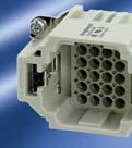
38 heavy mate DD Rated voltage 250 V Rated current 8 A... 9 A Termination: crimp Number of contacts: 24, 42, 72,


39 heavy mate DD Brief information Approvals, Testhouse Characteristics Approval-Number SEV 250 V, 10 A UL 600 V, 8,5 A E CSA 600 V, 10 A LR In general approvals refer to representative versions of the connector series. Extent and specification of tests upon request. 39
40 heavy mate DD Characteristics contact inserts General Characteristics Standard Value Number of contacts Termination technique Wire gauge 0.14 mm mm 2 Flammability UL 94 V-0 Electrical Characteristics Rated voltage IEC V (600 V UL / CSA) Pollution degree IEC (3 mated and locked) Installation (overvoltage) category IEC III Material group IEC III b Rated impulse withstand voltage IEC kv Current carrying capacity IEC see derating curves Contact resistance IEC m Ω Insulation resistance IEC Ω Climatical Characteristics Climatic category IEC / 100 / 21 Upper temperature IEC C Lower temperature IEC C Mechanical Characteristics Weight pin insert 44 g 50 g 63 g 86 g IP-degree of protection pin insert IEC unmated IP00 mated IP20 IP-degree of protection socket insert IEC unmated IP20 mated IP20 Weight socket insert 41 g 50 g 67 g 88 g Mechanical operation IEC > 500 mating cycles Materials Insert PBTP Colour insert grey Contacts CuZn (brass) Contact plating Ag (silver) Derating curves Curve Wire gauge a 0.75 mm 2 b 1.5 mm 2 crimp Curve Wire gauge a 0.75 mm 2 b 1.5 mm Curve Wire gauge a 0.75 mm 2 b 1.5 mm 2 Curve Wire gauge a 0.75 mm 2 b 1.5 mm 2 40


 Housings from page 196 Male")


")

41 heavy mate DD Contact inserts V/10 A Description Part Number Drawing Figure Contact insert 24 + for turned contacts Size E 6 (Please order contacts separately, see page 43) Housings from page 196 Male insert C146 10A for turned crimp contacts Female insert for turned crimp contacts C146 10B Contact insert 42 + for turned contacts Size E 10 (Please order contacts separately, see page 43) Housings from page 198 Male insert C146 10A for turned crimp contacts Female insert for turned crimp contacts C146 10B Contact insert 72 + for turned contacts Size E 16 (Please order contacts separately, see page 43) Housings from page 205 Male insert C146 10A for turned crimp contacts Female insert for turned crimp contacts C146 10B
42 heavy mate DD Contact inserts V/10 A Description Part Number Drawing Figure Contact insert for turned contacts Size E 24 (Please order contacts separately, see page 43) Housings from page 211 Male insert C146 10A for turned crimp contacts Female insert for turned crimp contacts C146 10B Contact insert for turned contacts Size E 48 (Please order contacts separately, see page 43) Housings from page 217 Male insert for turned crimp contacts C146 10A C146 10A Female insert for turned crimp contacts C146 10B C146 10B Pin layout Assembly instruction Male insert Female insert Panel cut out (insert) 42
43 heavy mate DD Crimp contacts Supplied as for wire gauge AWG Pieces Part Number Figure Male contact Female contact Turned crimp contacts single contact 1.6mm silver plating ,37 mm VN C VN C 0.5 mm VN C VN C ,0 mm VN C VN C 1.5 mm VN C VN C 2.5 mm VN C VN C gold plating mm VN C VN C 0.5 mm VN C VN C mm VN C VN C 1.5 mm VN C VN C 2.5 mm VN C VN C Tools for turned crimp contacts Description for wire gauge Part Number Contact locator Crimping dies Tool Removal tool for contacts FG Service crimping tool mm mm TA Crimping tool for single contacts Further tools see catalogue Tools mm mm mm 2 TA TA TA 0000 TA 0500 Stripping length see page


44 heavy mate E Rated voltage 500 V Rated current 16 A A Termination: screw, crimp, tension spring Numbers of contacts: 6, 10, 16, 24, 48 44


45 heavy mate E Brief information Approvals, Testhouse Characteristics Approval-Number SEV 400 V, 16 A UL 600 V, 16 A E CSA 600 V, 16 A In general approvals refer to representative versions of the connector series. Extent and specification of tests upon request. 45

 contact insert to contact insert 6, 10, 16, 24 contacts b) contact insert to housing 6, 10,16, 24")

46 heavy mate E General information General information Contact inserts without crimp contacts. Connectors series heavy mate E may be engaged or disengaged when live but without electrical load. If these connectors are mated or unmated under load, the load shall be reduced to 10 % of the rated current. No standard for this series, but: Interchangeable with other products a) contact insert to contact insert 6, 10, 16, 24 contacts b) contact insert to housing 6, 10,16, 24 contacts First-to-mate last-to-break protective ground contact Crimping tools and processing instructions see separate catalogue Tools. Low and high profile housings are usable. If wire ferrule are used, screw terminals without wire protection are preferred. Housings are designed according to DIN EN Contact inserts for screw termination, screw termination with wire protection and for crimp termination Screw termination Screw termination with wire protection Crimp termination Range of housings Size E6 Size E10 Size E16 Size E24 Size E48 46
47 heavy mate E Characteristics contact inserts General Characteristics Standard Value Number of contacts Termination technique Wire gauge mm 2 Flammability UL 94 V-0 crimp / screw / tension spring / push-in Electrical Characteristics Rated voltage IEC max. 500 V (600 V UL / CSA 1) ) Pollution degree IEC Material group IEC III b Installation (overvoltage) category IEC III Rated impulse withstand voltage IEC ,0 kv Current carrying capacity IEC see derating curves Rated current T amp = 40 C 22 A 19 A 19 A 18 A 18 A Contact resistance IEC < 5 mω Insulation resistance IEC Ω Climatical Characteristics Climatic category IEC / 125 / 21 Upper temperature IEC C Lower temperature IEC C Mechanical Characteristics IP-degree of protection pin insert 2) IEC unmated IP00 mated IP20 IP-degree of protection socket insert 2) IEC unmated IP20 mated IP20 Weight: male insert crimp (for stamped contacts) female insert crimp (for stamped contacts) male insert screw female insert screw Mechanical operation IEC > 500 mating cycles Materials Insert PC GV (Polycarbonat) Colour insert grey Screw contacts CuZn (brass) Contact plating Ag (silver) / Au (gold) 33 g 33 g 43 g 43 g 39 g 39 g 57 g 57 g 45 g 49 g 78 g 78 g 55 g 62 g 105 g 106 g 110 g 124 g 210 g 212 g 1) Label for CSA application see page 258 2) IP-degree of protection on ter mination side of screw version IP10 47

48 heavy mate E Contact inserts 6 + Size E6 500 V/16 A Housings from page 196 Description Part Number Drawing Figure Screw termination Male insert for screw termination C146 10A Male insert with wire protection for screw termination Female insert for screw termination C146 10A C146 10B Female insert with wire protection for screw termination C146 10B Tension spring Male insert with Tension spring C146 10A Female insert with Tension spring C146 10B Push-in Male insert with push-in connection C146 10A Female insert with push-in connection C146 10B


 Male insert C146")


49 heavy mate E Contact inserts 6 + Size E6 500 V/16 A Housings from page 196 Description Part Number Drawing Figure Stamped crimp contacts (Please order contacts separately, see page 58) Male insert C146 10A for stamped crimp contacts Female insert for stamped crimp contacts C146 10B Turned crimp contacts (Please order contacts separately, see page 58) Male insert C146 10A for turned crimp contacts Female insert for turned crimp contacts C146 10B Pin layout Assembly instruction Male insert Female insert Panel cut out (insert) Derating curves Stamped contacts Turned contacts Screw termination Curve a: 1.5 mm 2 wire gauge Curve b: 2.5 mm 2 wire gauge 49

50 heavy mate E Contact inserts 10 + Size E V/16 A Housings from page 198 Description Part Number Drawing Figure Screw termination Male insert for screw termination C146 10A Male insert with wire protection for screw termination Female insert for screw termination C146 10A C146 10B Female insert with wire protection for screw termination C146 10B Tension spring Male insert with Tension spring C146 10A Female insert with Tension spring C146 10B Push-in Male insert with push-in connection C146 10A Female insert with push-in connection C146 10B


 Male insert C146")


51 heavy mate E Contact inserts 10 + Size E V/16 A Housings from page 198 Description Part Number Drawing Figure Stamped crimp contacts (Please order contacts separately, see page 58) Male insert C146 10A for stamped crimp contacts Female insert for stamped crimp contacts C146 10B Turned crimp contacts (Please order contacts separately, see page 58) Male insert C146 10A for turned crimp contacts Female insert for turned crimp contacts C146 10B Pin layout Assembly instruction Male insert Female insert Panel cut out (insert) Derating curves Stamped contacts Turned contacts Screw termination Curve a: 1.5 mm 2 wire gauge Curve b: 2.5 mm 2 wire gauge 51
52 heavy mate E Contact inserts 16 + Size E V/16 A Housings from page 205 Description Part Number Drawing Figure Screw termination Male insert for screw termination C146 10A Male insert with wire protection for screw termination Female insert for screw termination C146 10A C146 10B Female insert with wire protection for screw termination C146 10B Tension spring Male insert with Tension spring C146 10A Female insert with Tension spring C146 10B Push-in Male insert with push-in connection C146 10A Female insert with push-in connection C146 10B


 Derating")


53 heavy mate E Contact inserts 16 + Size E V/16 A Housings from page 205 Description Part Number Drawing Figure Stamped crimp contacts (Please order contacts separately, see page 58) Male insert C146 10A for stamped crimp contacts Female insert for stamped crimp contacts C146 10B Turned crimp contacts (Please order contacts separately, see page 58) Male insert C146 10A for turned crimp contacts Female insert for turned crimp contacts C146 10B Pin layout Assembly instruction Male insert Female insert Panel cut out (insert) Derating curves Stamped contacts Turned contacts Screw termination Curve a: 1.5 mm 2 wire gauge Curve b: 2.5 mm 2 wire gauge 53
54 heavy mate E Contact inserts 24 + Size E V/16 A Housings from page 211 Description Part Number Drawing Figure Screw termination Male insert for screw termination C146 10A Male insert with wire protection for screw termination Female insert for screw termination C146 10A C146 10B Female insert with wire protection for screw termination C146 10B Tension spring Male insert with Tension spring C146 10A Female insert with Tension spring C146 10B Push-in Male insert with push-in connection C146 10A Female insert with push-in connection C146 10B


 Derating")


55 heavy mate E Contact inserts 24 + Size E V/16 A Housings from page 211 Description Part Number Drawing Figure Stamped crimp contacts (Please order contacts separately, see page 58) Male insert C146 10A for stamped crimp contacts Female insert for stamped crimp contacts C146 10B Turned crimp contacts (Please order contacts separately, see page 58) Male insert C146 10A for turned crimp contacts Female insert for turned crimp contacts C146 10B Pin layout Assembly instruction Male insert Female insert Panel cut out (insert) Derating curves Stamped contacts Turned contacts Screw termination Curve a: 1.5 mm 2 wire gauge Curve b: 2.5 mm 2 wire gauge 55
56 heavy mate E Contact inserts 48 + Size E V/16 A Housings from page 217 Description Part Number Drawing Figure Screw termination Male insert for screw termination C146 10A C146 10A Male insert with wire protection for screw termination Female insert for screw termination Female insert with wire protection for screw termination C146 10A C146 10A C146 10B C146 10B C146 10B C146 10B Stamped crimp contacts (Please order contacts separately, see page 58) Male insert for stamped crimp contacts C146 10A C146 10A Female insert for stamped crimp contacts C146 10B C146 10B Turned crimp contacts (Please order contacts separately, see page 58) Male insert for turned crimp contacts C146 10A C146 10A Female insert for turned crimp contacts C146 10B C146 10B
57 heavy mate E Contact inserts 48 + Size E V/16 A Housings from page 217 Pin layout Assembly instruction Male insert Female insert Panel cut out (insert) Derating curves Stamped contacts Turned contacts Screw termination Curve a: 1.5 mm 2 wire gauge Curve b: 2.5 mm 2 wire gauge 57
 0,5 1,0 1,5 1,5 2,5 Stamped")


58 heavy mate E Crimp technology Large range of wire gauges N N Gas-tight (coldwelding) 0,5 1,0 1,5 1,5 2,5 Stamped crimp contacts with insulation crimp, to absorbe mechanical stress from the crimped connection Insulation grip Mechanical retention spring stop on female and male contact Female contact Male contact High current carrying capacity Example single contact Curve a: 2.5 mm 2 wire gauge 58
59 heavy mate E Characteristics crimp contacts Stamped crimp contacts Electrical Characteristics Contact resistance IEC < 5 m Ω Mechanical Characteristics Mechanical operation IEC mating cycles Materials Male contact Cu Zn (brass) Female contact Cu Sn (tin bronce) Contact plating Ag (silver) / Au (gold) Turned crimp contacts Electrical Characteristics Contact resistance IEC m Ω Climatical Characteristics Upper temperature IEC C Lower temperature IEC C Mechanical Characteristics Mechanical operation IEC mating cycles Materials Male contact Cu Zn (brass) Female contact Cu Zn (brass) Contact plating Ag (silver) / Au (gold) 59
60 heavy mate E Stamped crimp contacts Supplied as for wire gauge AWG Pieces Part Number Figure Male contact Female contact Stamped single contacts silver plating mm VN VN mm VN VN gold plating mm VN VN mm VN VN Stamped Contacts on reel for hand crimp tools silver plating mm ZN ZN mm ZN ZN gold plating mm ZN ZN mm ZN ZN Stamped contacts on reel for crimp machines contact feeding left hand side silver plating mm TN TN mm TN TN Tools for turned crimp contacts Description for wire gauge Part Number Contact locator Crimping dies Tool Removal tool for contacts FG Crimping tool for stamped mm 2 TA TA TA 0000 single contacts mm 2 TA TA indent crimping tool for turned contacts mm TB Further tools see catalogue Tools 60 Stripping length see page


61 heavy mate E Turned crimp contacts Supplied as for wire gauge AWG Pieces Part Number Figure Male contact Female contact Turned crimp contacts single contact silver plating mm VN C VN C 0.5 mm VN C VN C mm VN C VN C 1.5 mm VN C VN C 2.5 mm VN C VN C 4.0 mm VN C VN C gold plating mm VN C VN C 0.5 mm VN C VN C mm VN C VN C 1.5 mm VN C VN C 2.5 mm VN C VN C 4.0 mm VN C VN C Tools for turned crimp contacts Description for wire gauge Part Number Contact locator Crimping dies Tool Removal tool for contacts FG Crimping tool for stamped single contacts 4-indent crimping tool for turned contacts Further tools see catalogue Tools mm 2 TA mm 2 TA TA TA TA 0000 TA 0500 TB
 Rated")

62 heavy mate EE Rated voltage 500 V (600 V UL / CSA) Rated current 16 A Termination: crimp Numbers of contacts: 10, 18, 32, 46 62


")


63 heavy mate EE Brief information Approvals, Testhouse Characteristics Approval-Number UL 600 V, 15 A E CSA 600 V, 16 A (LR ) In general approvals refer to representative versions of the connector series. Extent and specification of tests upon request. 63
64 heavy mate EE Characteristics contact inserts General Characteristics Standard Value Number of contacts Termination technique Wire gauge 0.5 mm mm 2 Flammability UL 94 V-0 Electrical Characteristics Rated voltage IEC V (600 V UL / CSA) Pollution degree IEC Installation (overvoltage) category IEC III Material group IEC III b Rated impulse withstand voltage IEC kv Current carrying capacity IEC see derating curves Contact resistance IEC m Ω Insulation resistance IEC Ω Climatical Characteristics Climatic category IEC / 100 / 21 Upper temperature IEC C Lower temperature IEC C Mechanical Characteristics Mechanical operation IEC > 500 mating cycles IP-degree of protection pin insert IEC unmated IP00 mated IP20 IP-degree of protection socket insert IEC unmated IP20 mated IP20 Materials Insert PC Colour insert grey Contacts CuZn (brass) Contact plating Ag (silver) / Au (gold) Derating curves Curve Wire gauge a 0.5 mm 2 b 2.5 mm 2 c 4.0 mm 2 crimp Curve Wire gauge a 0.5 mm 2 b 2.5 mm 2 c 4.0 mm Curve Wire gauge a 0.5 mm 2 b 2.5 mm 2 c 4.0 mm 2 Curve Wire gauge a 0.5 mm 2 b 2.5 mm 2 c 4.0 mm 2 64
65 heavy mate EE Contact inserts V/15 A Description Part Number Drawing Figure Contact insert10 + Size E 6 (Please order contacts separately, see page 67) Housings from page 196 Male insert C146 10A for turned crimp contacts Female insert for turned crimp contacts C146 10B Pin layout Assembly instruction Male insert Female insert Panel cut out (insert) Description Part Number Drawing Figure Contact insert 18 + Size E 10 (Please order contacts separately, see page 67) Housings from page 198 Male insert C146 10A for turned crimp contacts Female insert for turned crimp contacts C146 10B Pin layout Assembly instruction Male insert Female insert Panel cut out (insert)
66 heavy mate EE Contact inserts V/16 A Description Part Number Drawing Figure Contact insert 32 + Size E 16 (Please order contacts separately, see page 67) Housings from page 205 Male insert for turned crimp contacts C146 10A Female insert for turned crimp contacts C146 10B Pin layout Assembly instruction Male insert Female insert Panel cut out (insert) Description Part Number Drawing Figure Contact insert 46 + Size E 24 (Please order contacts separately, see page 67) Housings from page 211 Male insert for turned crimp contacts C146 10A Female insert for turned crimp contacts C146 10B Pin layout Assembly instruction Male insert Female insert Panel cut out (insert)
67 heavy mate EE Crimp contacts Supplied as for wire gauge AWG Pieces Part Number Figure Male contact Female contact Turned crimp contacts single contact 2.5mm silver plating 0.5 mm VN C VN C mm VN C VN C 1.5 mm VN C VN C 2.5 mm VN C VN C 4.0 mm VN C VN C gold plating 0.5 mm VN C VN C mm VN C VN C 1.5 mm VN C VN C 2.5 mm VN C VN C 4.0 mm VN C VN C Tools for turned crimp contacts Description for wire gauge Part Number Contact locator Crimping dies Tool Removal tool for contacts FG Crimping tool for stamped single contacts 4-indent crimping tool for turned contacts Further tools see catalogue Tools mm 2 TA mm 2 TA TA TA TA 0000 TA 0500 TB Stripping length see page


68 heavy mate E / FE / KO Rated voltage 400 V Material contacts: iron-constantan Rated current 10 A Number of contacts: 6, 10, 16, 24 68


69 heavy mate E / FE / KO Brief information 69
70 heavy mate E / FE / KO General information Connectors with iron (FE) and constantan (CO) contacts are basically used in measuring and control circuits to serve as interface between FE/CO thermocouples and control unit, i. e. temperature control of moulds in injection moulding machines. Through the use of FE/CO connectors in the thermocouple circuit Amphenol s Industial Connectors with iron (FE) an Contantan (CO) contacts are used to connect FE/CO thermocouples with electronic signal amplifiers in measuring and control circuits, i. e. for temperature control of moulding machines. the measuring results are more accurate, thus the tolerance of the temperature control is much narrower. Errors with various combinations The connection of unlike metals (FE/Brass and CO/Brass) generate thermoelectric voltage errors in the mesuring circuit caused by the flow from iron wire to the brass contact or by temperature changes at the contact elements. Contact without Thermo Contacts with Thermo Contacts Material Nominal Temp. MS/FE MS/KO FE/FE KO/KO 100 C + 4 % - 16 % - 4 % - 2 % 200 C % - 8 % - 3 % % 300 C % % % 0 % 400 C % % % 0 % By using FE/CO contacts respectively these deviations will be minimized. Material / Temperature Range Temperatur range Material/measurement procedure < 150 C any/resistance measurement 150 C C FE-CO (iron/constantan) 450 C - approx C Ni/Cr-Ni (Nickel/Chrome/Nickel) Temperature changes cause errors Nominale Ambient temperature mv/ C Temp. C 70
71 heavy mate E / FE / KO Characteristics contact inserts General Characteristics Standard Value Number of contacts Termination technique screw Wire gauge 0.25 mm mm 2 Flammability UL 94 V-0 Electrical Characteristics Rated voltage IEC V Pollution degree IEC Installation (overvoltage) category IEC III Material group IEC III b Current carrying capacity IEC kv Rated current T amp = 40 C 10 A Contact resistance IEC m Ω Insulation resistance IEC Ω Climatical Characteristics Climatic category IEC / 100 / 21 Upper temperature IEC C Lower temperature IEC C Mechanical Characteristics IP-degree of protection pin insert 1) IEC unmated IP00 mated IP20 IP-degree of protection socket insert 1) IEC unmated IP20 mated IP20 Weight pin insert 45 g 60 g 78 g 105 g Weight socket insert 45 g 60 g 78 g 105 g Mechanical operation IEC mating cycles Materials Insert PA, GV (Polyamid) Colour insert grey Contacts iron; gal cd 4 constantan = without plating 1) IP-degree of protection on ter mination side of screw version IP10 71


72 heavy mate E / FE / KO Contact inserts Housings from page 184 Description Part Number Drawing Figure Contact insert 6 + Male insert with wire protection with iron-constantan contacts C146 10A Female insert with wire protection C146 10B Pin layout Assembly instruction Male insert Female insert Panel cut out (insert) Description Part Number Drawing Figure Contact insert 10 + Male insert with wire protection with iron-constantan contacts C146 10A Female insert with wire protection C146 10B Pin layout Assembly instruction Male insert Female insert Panel cut out (insert) 72
73 heavy mate E / FE / KO Contact inserts Housings from page 184 Description Part Number Drawing Figure Contact insert 16 + Male insert with wire protection with iron-constantan contacts C146 10A Female insert with wire protection C146 10B Pin layout Assembly instruction Male insert Female insert Panel cut out (insert) Description Part Number Drawing Figure Contact insert 24 + Male insert with wire protection with iron-constantan contacts C146 10A Female insert with wire protection C146 10B Pin layout Assembly instruction Male insert Female insert Panel cut out (insert) 73


74 heavy mate F Modular connector Compatible with market standard Rated voltage up to 1000 V Rated current up to 100 A Termination: crimp Numbers of contacts:

75 heavy mate F Brief information Approvals, Testhouse Characteristics Approval-Number UL in preparation in preparation CSA in preparation in preparation 75
76 heavy mate F General information General information Modules inserts without crimp contacts, crimping tools see separate catalogue Tools. Contacts must be ordered separatly, processing instructions see catalogue Tools. Connectors series heavy mate F may be engaged or disengaged when live but without electrical load. If these connectors are mated or unmated under load, the load shall be reduced to 10 % of rated current. Advantages of the system No standard but interchangeable with competitive products. Housings are designed according to DIN EN Simply connecting of the modules and frames. First-to-mate last-to-break protective ground contact We recommend using the high profile housings / hoods for the heavy mate F inserts. Empty modul spaces have to be filled with blind modules. Torque for PE connection 1.2 Nm Range of housings Size E6 Size E10 Size E16 Size E24 Size E48 76
 1 x 17 contacts b) 2 x 12 contacts c) 1 x 6 contacts + 1 x 12 contacts d) 1 x 3 contacts + 1 x 6 contacts")
 not possible due to voltage b) not possible due to voltage c) not possible due to current d)")
77 heavy mate F How to select a solution with series heavy mate F? Requirements 3 x 400V; 50A; 6mm² wire gauge 8 x 250V; 8A; 1.5mm² wire gauge 5 x 400V; 15A; 4mm² wire gauge Solution 1. Check how 16 contacts can be realized; see modules overview on page 78 Possible selection: a) 1 x 17 contacts b) 2 x 12 contacts c) 1 x 6 contacts + 1 x 12 contacts d) 1 x 3 contacts + 1 x 6 contacts + 1 x 12 contacts 2. Check technical parameters / solution, see detail pages of the modules from page 84 Possible selection: a) not possible due to voltage b) not possible due to voltage c) not possible due to current d) POSSIBLE 3. Choose matching contact, see detail page of the modules on page 84 Possible selection: a) 3 contacts = C146 10A contacts = VN C b) 6 contacts = C146 10A contacts = VN C c) 12 contacts = C146 10A contacts = VN C 4. Choose matching frame, see frames on page 82 Solution: C146 10P Choose matching housing, see housings on page 184 Solution: C146 21R Schematic construction 77

78 heavy mate F Modules Overview Description Part Number Drawing Figure 2 contacts module for turned contacts, 1000V, details see page 84 Pin modules C146 10A Socket modules C146 10B contacts module for turned contacts, details see page 86 Pin modules C146 10A Socket modules C146 10B contacts module for turned contacts, 830 V, details see page 88 Pin modules C146 10A Socket modules C146 10B ) If connectors are mounted in non conductive housings both protective earthing terminals shall be mounted.


79 heavy mate F Modules Overview Description Part Number Drawing Figure 6 contacts module for turned contacts, 500 V, details see page 90 Pin modules C146 10A Socket modules C146 10B contacts module for turned contacts, 400 V, details see page 92 Pin modules C146 10A Socket modules C146 10B contacts module for turned contacts, 250 V, details see page 94 Pin modules C146 10A Socket modules C146 10B ) If connectors are mounted in non conductive housings both protective earthing terminals shall be mounted. 79

 If connectors are mounted in non conductive housings both protective earthing terminals shall be")
80 heavy mate F Modules Overview Description Part Number Drawing Figure 17 contacts module for turned contacts, 160 V, details see page 96 Pin modules C146 10A Socket modules C146 10B contacts module for turned contacts, 500 V, details see page 98 Pin modules C146 10A Socket modules C146 10B Shielded module 2x4 contacts for bus signals,, 50 V, details see page 100 Pin modules C146 10A C146 10A Socket modules C146 10B C146 10B ) If connectors are mounted in non conductive housings both protective earthing terminals shall be mounted.
81 heavy mate F Modules Overview Description Part Number Drawing Figure Blind module, details see page 102 Blind module with C146 10H centering function Blind module standard C146 10H


 If connectors are mounted in non conductive housings both")
82 heavy mate F Frames Description Part Number Drawing Figure Frame for 2 modules Size E6 Housings from page 196 Frame for pin modules C146 10P Frame for socket modules C146 10S Frame for 3 modules Size E10 Housings from page 198 Frame for pin modules C146 10P Frame for socket modules C146 10S Frame for 4 modules Size E16 Housings from page 205 Frame for pin modules C146 10P Frame for socket modules C146 10S It is possible to mount socket modules in frames for pin modules (possibility of inverse configuration). 1) If connectors are mounted in non conductive housings both protective earthing terminals shall be mounted.


83 heavy mate F Frames Description Part Number Drawing Figure Frame for 6 modules Size E24 Housings from page 211 Frame for pin modules C146 10P Frame for socket modulesc146 10S ) If connectors are mounted in non conductive housings both protective earthing terminals shall be mounted. 83
84 heavy mate F Characteristics 2 contacts high current module General Characteristics Standard Value Number of contacts 2 Termination technique crimp Wire Gauge mm² (AWG 8-2) Flammability UL94 V-0 Elektrische Kennwerte Rated voltage IEC V Pollution degree IEC Installation (overvoltage) category IEC III Material group IEC II (PA) Rated impulse withstand voltage IEC kv Current carrying capacity IEC see derating curves Contact resistance IEC mω Insulation resistance IEC Ω Climatical Characteristics Climatic category IEC /125/21 Upper temperature IEC C Lower temperature IEC C Mechanical Characteristics Mechanical operation IEC mating cycles IP-degree of protection IEC IP00 (pin insert) / IP20 (socket insert) Materials Module PA6.6 GF Colour module black Contact CuZn (brass) Contact plating Ag (silver) Derating Curves In preparation 84


85 heavy mate F 2 contacts high current module + crimp contacts Description Part Number Drawing Figure 2 contacts high current module (Please order contacts separately) Pin module C146 10A Socket module C146 10B Supplied as for wire gauge AWG Part Number Figure Male contact Female contact Turned 8 mm crimp contacts single contact silver plating 10 mm 2 8 N N mm 2 6 N N mm 2 4 N N mm 2 2 N N Tools Description for wire gauge Part Number Contact locator Crimping dies Tool Crimping dies 25 mm 2 35 mm 2 TE For use in pneumatic crimping tool EK12042 by Klauke or AHPW 400C by Neko. Further tools see catalogue Tools 85
86 heavy mate F Characteristics 3 contacts module General Characteristics Standard Value Number of contacts 3 Termination technique crimp Wire Gauge mm² (AWG 16-10) Flammability UL94 V-0 Electrical Characteristics Rated voltage IEC V (conductor earth) 690 V (conductor conductor) Pollution degree IEC Installation (overvoltage) category IEC III Material group IEC II (PA) Rated impulse withstand voltage IEC kv Current carrying capacity IEC see derating curves Contact resistance IEC mω Insulation resistance IEC Ω Climatical Characteristics Climatic category IEC /125/21 Upper temperature IEC C Lower temperature IEC C Mechanical Characteristics Mechanical operation IEC mating cycles IP-degree of protection IEC IP00 (pin insert) / IP20 (socket insert) Materials Module PA6.6 GF Colour module black Contact CuZn (brass) Contact plating Ag (silver) / Au (gold) Derating Curves Current carrying capacity (A) a b Curve Wire gauge a 4 mm 2 b 6 mm Temperature ( C) 86
87 heavy mate F 3 contacts module + crimp contacts Description Part Number Drawing Figure 3 contacts module (Please order contacts separately) Pin module for wire gauge mm 2 for wire gauge 10 mm 2 C146 10A C146 10A Socket module for wire gauge mm 2 for wire gauge 10 mm 2 C146 10B C146 10B Supplied as for wire gauge AWG Pieces Part Number Figure Male contact Female contact Turned 4 mm crimp contacts single contact silver plating 1.5 mm VN C VN C 2.5 mm VN C VN C 4 mm VN C VN C 6 mm VN C VN C 10 mm VN C VN C Tools for 4 mm 2 turned contacts Description for wire gauge Part Number Contact locator Crimping dies Tool Removal tool for contacts TB TP FG indet crimping tool 1) TB Further tools see catalogue Tools 1) Incl. calibration pin set, locator 87
88 heavy mate F Characteristics 4 contacts module General Characteristics Standard Value Number of contacts 4 Termination technique crimp Wire Gauge mm² (AWG 16-10) Flammability UL94 V-0 Electrical Characteristics Rated voltage IEC V Pollution degree IEC Installation (overvoltage) category IEC III Material group IEC II (PA) Rated impulse withstand voltage IEC kv Current carrying capacity IEC see derating curves Contact resistance IEC mω Insulation resistance IEC Ω Climatical Characteristics Climatic category IEC /125/21 Upper temperature IEC C Lower temperature IEC C Mechanical Characteristics Mechanical operation IEC mating cycles IP-degree of protection IEC IP20 Materials Module PA6.6 GF Colour module black Contact CuZn (brass) Contact plating Ag (silver) Derating Curves In preparation 88
89 heavy mate F 4 contacts module + crimp contacts Description Part Number Drawing Figure 4 contacts module (Please order contacts separately) Pin module C146 10A Socket module C146 10B Supplied as for wire gauge AWG Pieces Part Number Figure Male contact Female contact Turned 4 mm crimp contacts single contact silver plating 1.5 mm VN C VN C 2.5 mm VN C VN C 4 mm VN C VN C 6 mm VN C VN C Tools for 4 mm 2 turned contacts Description for wire gauge Part Number Contact locator Crimping dies Tool Removal tool for contacts TB TP FG indet crimping tool 1) TB Further tools see catalogue Tools 1) Incl. calibration pin set, locator 89
90 heavy mate F Characteristics 6 contacts module General Characteristics Standard Value Number of contacts 6 Termination technique crimp Wire Gauge mm² (AWG 20-12) Flammability UL94 V-0 Electrical Characteristics Rated voltage IEC V Pollution degree IEC Installation (overvoltage) category IEC III Material group IEC II (PA) Rated impulse withstand voltage IEC kv Current carrying capacity IEC see derating curves Contact resistance IEC mω Insulation resistance IEC Ω Climatical Characteristics Climatic category IEC /125/21 Upper temperature IEC C Lower temperature IEC C Mechanical Characteristics Mechanical operation IEC mating cycles IP-degree of protection IEC IP00 (pin insert) / IP20 (socket insert) Materials Module PA6.6 GF Colour module black Contact CuZn (brass) Contact plating Ag (silver) / Au (gold) Derating Curves Current carrying capacity (A) a b Curve Wire gauge a 1.5 mm 2 b 2.5 mm Temperature ( C) 90

91 heavy mate F 6 contacts module + crimp contacts Description Part Number Drawing Figure 6 contacts module (Please order contacts separately) Pin module C146 10A Socket module C146 10B Supplied as for wire gauge AWG Pieces Part Number Figure Male contact Female contact Turned 2.5 mm crimp contacts single contact silver plating 0.5 mm VN C VN C mm VN C VN C 1.5 mm VN C VN C 2.5 mm VN C VN C 4.0 mm VN C VN C gold plating 0.5 mm VN C VN C mm VN C VN C 1.5 mm VN C VN C 2.5 mm VN C VN C 4.0 mm VN C VN C Tools for turned contacts Description for wire gauge Part Number Contact locator Crimping dies Tool Removal tool for contacts FG Crimping tool for turned single contacts 4-indet crimping tool for turned contacts Further tools see catalogue Tools mm 2 TA mm 2 TA TA TA TA 0000 TA 0500 TB
92 heavy mate F Characteristics 8 contacts module General Characteristics Standard Value Number of contacts 8 Termination technique crimp Wire Gauge mm² (AWG 20-12) Flammability UL94 V-0 Electrical Characteristics Rated voltage IEC V Pollution degree IEC Installation (overvoltage) category IEC III Material group IEC II (PA) Rated impulse withstand voltage IEC kv Current carrying capacity IEC see derating curves Contact resistance IEC mω Insulation resistance IEC Ω Climatical Characteristics Climatic category IEC /125/21 Upper temperature IEC C Lower temperature IEC C Mechanical Characteristics Mechanical operation IEC mating cycles IP-degree of protection IEC IP00 (pin insert) / IP20 (socket insert) Materials Module PA6.6 GF Colour module black Contact CuZn (brass) Contact plating Ag (silver) / Au (gold) Derating Curves Current carrying capacity (A) a b Curve Wire gauge a 1.5 mm 2 b 2.5 mm Temperature ( C) 92
93 heavy mate F 8 contacts module + crimp contacts Description Part Number Drawing Figure 8 contacts module (Please order contacts separately) Pin module C146 10A Socket module C146 10B Supplied as for wire gauge AWG Pieces Part Number Figure Male contact Female contact Turned 2.5 mm crimp contacts single contact silver plating 0.5 mm VN C VN C mm VN C VN C 1.5 mm VN C VN C 2.5 mm VN C VN C 4.0 mm VN C VN C gold plating 0.5 mm VN C VN C mm VN C VN C 1.5 mm VN C VN C 2.5 mm VN C VN C 4.0 mm VN C VN C Tools for turned contacts Description for wire gauge Part Number Contact locator Crimping dies Tool Removal tool for contacts FG Crimping tool for turned single contacts 4-indet crimping tool for turned contacts Further tools see catalogue Tools mm 2 TA mm 2 TA TA TA TA 0000 TA 0500 TB
94 heavy mate F Characteristics 12 contacts module General Characteristics Standard Value Number of contacts 12 Termination technique crimp Wire Gauge mm² (AWG 26-14) Flammability UL94 V-0 Electrical Characteristics Rated voltage IEC V (conductor earth) 400 V (conductor conductor) Pollution degree IEC Installation (overvoltage) category IEC III Material group IEC II (PA) Rated impulse withstand voltage IEC kv Current carrying capacity IEC see derating curves Contact resistance IEC mω Insulation resistance IEC Ω Climatical Characteristics Climatic category IEC /100/21 Upper temperature IEC C Lower temperature IEC C Mechanical Characteristics Mechanical operation IEC mating cycles IP-degree of protection IEC IP00 (pin insert) / IP20 (socket insert) Materials Module PA6.6 GF Colour module black Contact CuZn (brass) Contact plating Ag (silver) / Au (gold) Derating Curves Current carrying capacity (A) a b Curve Wire gauge a 1.0 mm 2 b 1.5 mm Temperature ( C) 94
95 heavy mate F 12 contacts module + crimp contacts Description Part Number Drawing Figure 12 contacts module (Please order contacts separately) Pin module C146 10A Socket module C146 10B Supplied as for wire gauge AWG Pieces Part Number Figure Male contact Female contact Turned crimp contacts single contact silver plating mm VN C VN C 0.5 mm VN C VN C mm VN C VN C 1.5 mm VN C VN C 2.5 mm VN C VN C gold plating mm VN C VN C 0.5 mm VN C VN C mm VN C VN C 1.5 mm VN C VN C 2.5 mm VN C VN C Tools for turned contacts Description for wire gauge Part Number Contact locator Crimping dies Tool Removal tool for contacts FG Service crimping tool mm mm TA Further tools see catalogue Tools 95
96 heavy mate F Characteristics 17 contacts module General Characteristics Standard Value Number of contacts 17 Termination technique crimp Wire Gauge mm² (AWG 26-14) Flammability UL94 V-0 Electrical Characteristics Rated voltage IEC V Pollution degree IEC Installation (overvoltage) category IEC III Material group IEC II (PA) Rated impulse withstand voltage IEC kv Current carrying capacity IEC see derating curves Contact resistance IEC mω Insulation resistance IEC Ω Climatical Characteristics Climatic category IEC /100/21 Upper temperature IEC C Lower temperature IEC C Mechanical Characteristics Mechanical operation IEC mating cycles IP-degree of protection IEC IP00 (pin insert) / IP20 (socket insert) Materials Module PA6.6 GF Colour module black Contact CuZn (brass) Contact plating Ag (silver) / Au (gold) Derating Curves Current carrying capacity (A) a c b Curve Wire gauge a 0.5 mm 2 b 1.0 mm 2 c 1.5 mm Temperature ( C) 96

97 heavy mate F 17 contacts module + crimp contacts Description Part Number Drawing Figure 17 contacts module (Please order contacts separately) Pin module C146 10A Socket module C146 10B Supplied as for wire gauge AWG Pieces Part Number Figure Male contact Female contact Turned crimp contacts single contact silver plating mm VN C VN C 0.5 mm VN C VN C mm VN C VN C 1.5 mm VN C VN C 2.5 mm VN C VN C gold plating mm VN C VN C 0.5 mm VN C VN C mm VN C VN C 1.5 mm VN C VN C 2.5 mm VN C VN C Tools for turned contacts Description for wire gauge Part Number Contact locator Crimping dies Tool Removal tool for contacts FG Service crimping tool mm mm TA Further tools see catalogue Tools 97
98 heavy mate F Characteristics 20 contacts module General Characteristics Standard Value Number of contacts 20 Termination technique crimp Wire Gauge mm² (AWG 20-12) Flammability UL94 V-0 Electrical Characteristics Rated voltage IEC V Pollution degree IEC Installation (overvoltage) category IEC III Material group IEC II (PA) Rated impulse withstand voltage IEC kv Current carrying capacity IEC see derating curves Contact resistance IEC mω Insulation resistance IEC Ω Climatical Characteristics Climatic category IEC /125/21 Upper temperature IEC C Lower temperature IEC C Mechanical Characteristics Mechanical operation IEC mating cycles IP-degree of protection IEC IP00 (pin insert) / IP20 (socket insert) Materials Module PA6.6 GF Colour module black Contact CuZn (brass) Contact plating Ag (silver) / Au (gold) Derating Curves Current carrying capacity (A) c b a Curve Wire gauge a 1,5 mm 2 b 2,5 mm 2 c 4,0 mm Temperature ( C) 98

99 heavy mate F 20 contacts module + crimp contacts Description Part Number Drawing Figure 20 contacts module (Please order contacts separately) Pin module C146 10A Socket module C146 10B Supplied as for wire gauge AWG Pieces Part Number Figure Male contact Female contact Turned 2.5 mm crimp contacts single contact silver plating 0.5 mm VN C VN C mm VN C VN C 1.5 mm VN C VN C 2.5 mm VN C VN C 4.0 mm VN C VN C gold plating 0.5 mm VN C VN C mm VN C VN C 1.5 mm VN C VN C 2.5 mm VN C VN C 4.0 mm VN C VN C Tools for turned contacts Description for wire gauge Part Number Contact locator Crimping dies Tool Removal tool for contacts FG Crimping tool for turned single contacts 4-indet crimping tool for turned contacts Further tools see catalogue Tools mm 2 TA mm 2 TA TA TA TA 0000 TA 0500 TB
100 heavy mate F Characteristics Shielded module General Characteristics Standard Value Number of contacts 2X4 Termination technique crimp Wire Gauge mm² (AWG 26-14) Flammability UL94 V-0 Electrical Characteristics Rated voltage IEC V Pollution degree IEC Installation (overvoltage) category IEC Material group IEC II (PA) Rated impulse withstand voltage IEC ,8 kv Current carrying capacity at 40 C IEC A Durchgangswiderstand IEC mω Climatical Characteristics Climatic category IEC /125/21 Upper temperature IEC C Lower temperature IEC C Mechanical Characteristics Mechanical operation IEC mating cycles Materials Module PA Colour module black Contact Cu-alloy Contact plating Ag (silver) / Au (gold) Modules for shielding surrender independently of the housing. For the transmission of bus signals. 100


101 heavy mate F Shielded module + crimp contacts Description Part Number Drawing Figure Contact insert 2x4 contacts (Please order contacts separately) Pin module C146 10A Male contact carriers 4 contacts C146 10A Socket module C146 10B Female contact carriers 4 contacts C146 10B Potential balance spring Pin/ Socket module N for male module for female module Supplied as for wire gauge AWG Pieces Part Number Figure Male contact Female contact Turned 1.5 mm crimp contacts single contact mm² VN C VN C 0.5 mm² VN C VN C mm² VN C VN C 1.5 mm² VN C VN C 2.5 mm² VN C VN C Tools Description for wire gauge Part Number Contact locator Crimping dies Tool Crimping tool TA 0000 oder TA 0500 Crimping dies - - TA Contact locator - TA Removal tool for contacts FG Further tools see catalogue Tools 101
102 heavy mate F Characteristics Blind module General Characteristics Standard Value Number of contacts 0 Flammability UL94 V-0 Electrical Characteristics Rated voltage IEC Pollution degree IEC Installation (overvoltage) category IEC III Material group IEC II (PA) Climatical Characteristics Climatic category IEC /100/21 Upper temperature IEC C Lower temperature IEC C Mechanical Characteristics Mechanical operation IEC mating cycles Materials Module PA6.6 GF Modules with centering function allow the use of the modular system in rack and panel applications without housing. The modules align a floating frame so that modules can be plugged centred. For optimal function two modules must be used in the frame. 102
103 heavy mate F Blind module Description Part Number Drawing Figure Blind module Blind module with centering function C146 10H Blind module standard C146 10H


104 heavy mate HSE Rated voltage 400 V Rated current 42 A Termination: screw Number of contacts: 6 104


105 heavy mate HSE Brief information Approvals, Testhouse Characteristics Approval-Number UL 600 V, 35 A E CSA 600 V, 35 A In general approvals refer to representative versions of the connector series. Extent and specification of tests upon request. 105
106 heavy mate HSE Characteristics contact inserts General Characteristics Standard Value Number of contacts 6 + Termination technique screw Wire gauge mm 2 (Ø 3.4 mm) Flammability UL 94 V-0 Electrical Characteristics Rated voltage IEC V (600 V UL / CSA 1) ) Pollution degree IEC Installation (overvoltage) category IEC III Material group IEC II Rated impulse withstand voltage IEC kv Rated current IEC see derating curves Rated current T amp = 40 C 42 A Contact resistance IEC m Ω Insulation resistance IEC Ω Climatical Characteristics Climatic category IEC / 125 / 21 Upper temperature IEC C Lower temperature IEC C Mechanical Characteristics IP-degree of protection pin insert IEC unmated IP00 mated IP20 IP-degree of protection socket insert IEC unmated IP20 mated IP20 Weight pin insert 80 g Weight socket insert 80 g Mechanical operation IEC mating cycles Materials Insert PA, GV Colour insert black Contacts Cu Zn (brass) Contact plating Ag (silver) 106 1) Label for CSA application see page 258 2) IP-degree of protection on termination side IP10


 Derating")

107 heavy mate HSE Contact inserts 6 + Size E V/42 A Housings from page 205 Description Part Number Drawing Figure Contact insert 6 + Male insert with wire protection for screw termination C146 10A Female insert with wire protection for screw termination C146 10B Pin layout Assembly instruction Male insert Female insert Panel cut out (insert) Derating curves Curve a: 6 mm 2 screw contact 107


108 heavy mate HvE Rated voltage 660 V Rated current 16 A A Termination: screw 2 delayed mating contacts Number of contacts: 3, 6, 10, 16, 20, 26,


109 heavy mate HvE Brief information Approvals, Testhouse Characteristics Approval-Number UL 600 V, 16 A E CSA 600 V, 16 A In general approvals refer to representative versions of the connector series. Extent and specification of tests upon request. 109
110 heavy mate HvE General information Construction of connectors Type HvE The connectors of series heavy mate HvE are based on series heavy mate E with the following deviations: Inserts The HVE-inserts with 3, 6 and 10 contacts are basically the same as the 10, 16 and 24-contacts inserts of series heavy mate E. However they are only partly loaded with contacts and have two delayed mating pilot duty contacts. Only type 16 HVE has special inserts with a different contact arrangement. The mounting dimensions are however identical with the 24 contacts version of heavy mate E. The delayed mating contacts are intended for switching a relay coil for electrically locking in order to have unloaded socket contacts in an unmated condition. heavy mate E inserts with pin contacts are not intermatable with heavy mate HvE inserts with socket contacts due to a) two empty contact holes are closed at 3, 6 and 10 contact inserts. b) the 16 contacts HVE insert has a different contact arrangement. If connectors without breaking capacity are used as connectors with breaking capacity the electrical power data must be reduced in accordance with the manufacturer's specification. These specifications are available from the manufacturer. Housings: (made of aluminium) heavy mate E housings with an inside insulation (plastic foil) are used for the 16-contacts insert. The inside barriers at the narrow sides preventing mounting of 660 V-inserts in 400 V housings are removed and the 16-contacts insert is now mountable. No standard for this series,but: Intermateable and exchangeable with other makes a) Contact insert to contact insert b) Contact insert to housing 6, 10,16, 24 pin Housings are designed according to DIN EN First-to-mate last-to-break protective ground contact 110
111 heavy mate HvE Characteristics contact inserts General Characteristics Standard Value Number of contacts ) 32 Termination technique screw Wire gauge mm 2 Flammability UL 94 V-0 Electrical Characteristics Rated voltage IEC V 1) (600 V UL / CSA 2) Pollution degree IEC Installation (overvoltage) category IEC III Material group IEC III a II IIIa 3) II Rated impulse withstand voltage IEC kv Current carrying capacity IEC see derating curves Contact resistance IEC m Ω Insulation resistance IEC Ω Climatical Characteristics Climatic category IEC /125/21 Upper temperature IEC C Lower temperature IEC C Mechanical Characteristics IP-degree of protection pin insert 4) IEC unmated IP00 mated IP20 IP-degree of protection socket insert 4) IEC unmated IP20 mated IP20 Weight pin insert 49 g 63 g 81 g 107 g 162 g 189 g 214 g Weight socket insert 49 g 63 g 81 g 107 g 162 g 189 g 214 g Mechanical operation IEC mating cycles Materials Insert PC, GV PA,GV PC,GV 3) PA,GV Colour insert grey black grey 3) black Contacts Cu Zn (brass) Contact plating Ag (silver) 1) for working contacts, 400 V for mating contacts 2) Label for CSA application see page 258 3) Combination 10 and 16 ways, i.e. material PC and PA 4) IP-degree of protection on termination side IP10 111


112 heavy mate HvE Contact inserts Size E V/16 A Housings from page 198 Description Part Number Drawing Figure Contact insert 3 + Male insert with wire protection for screw termination + 2 (delayed mating contacts) C146 10A Female insert with wire protection for screw termination C146 10B Pin layout Assembly instruction Male insert Female insert Panel cut out (insert) Working contact Mating contact Without contact Derating curves Notice restriction of wire Curve a: 1.5 mm 2 screw contacts Curve b: 2.5 mm 2 screw contacts 112


113 heavy mate HvE Contact inserts Size E V/16 A Housings from page 205 Description Part Number Drawing Figure Contact insert 6 + Male insert with wire protection for screw termination + 2 (delayed mating contacts) C146 10A Female insert with wire protection for screw termination C146 10B Pin layout Assembly instruction Male insert Female insert Panel cut out (insert) Working contact Mating contact Without contact Derating-Kurven Notice restriction of wire Curve a: 1.5 mm 2 screw contacts Curve b: 2.5 mm 2 screw contacts 113
114 heavy mate HvE Contact inserts Size E V/16 A Housings from page 211 Description Part Number Drawing Figure Contact insert 10 + Male insert with wire protection for screw termination + 2 (delayed mating contacts) C146 10A Female insert with wire protection for screw termination C146 10B Pin layout Assembly instruction Male insert Female insert Panel cut out (insert) Working contact Mating contact Without contact Derating curves Notice restriction of wire Curve a: 1.5 mm 2 screw contacts Curve b: 2.5 mm 2 screw contacts 114
115 heavy mate HvE Contact inserts Size E V/16 A Housings from page 219 Description Part Number Drawing Figure Contact insert 16 + Male insert with wire protection for screw termination + 2 (delayed mating contacts) C146 10A Male insert without wire protection for screw termination Female insert with wire protection for screw termination Female insert without wire protection for screw termination C146 10A C146 10B C146 10B Pin layout Assembly instruction Male insert Female insert Panel cut out (insert) Working contact Mating contact Derating curves Notice restriction of wire Curve a: 1.5 mm 2 screw contacts Curve b: 2.5 mm 2 screw contacts 115
116 heavy mate HvE Contact inserts Size E V/16 A Housings from page 217 Description Part Number Drawing Figure Contact insert 32 + Male insert with wire protection for screw termination + 4 (delayed mating contacts) C146 10A Female insert with wire protection for screw termination C146 10B Pin layout Male insert Female insert Working contact Mating contact 116
117 heavy mate HvE Your notes 117


118 heavy mate K Power + signal as mixed arrangement Rated voltage up to 830 V Termination: screw, crimp 118

119 heavy mate K Brief information Approvals, Testhouse Characteristics Approval-Number UL In preparation In preparation CSA In preparation In preparation 119
120 heavy mate K Characteristics contact inserts 4/0 + 4 / 2 General Characteristics Standard Value Number of contacts 4/0 (4 Power) 4/2 + PE (4 Power + 2 Signal) Termination technique screw Wire gauge mm² (AWG 16-6) Flammability UL94 V-0 Electrical Characteristics Rated voltage IEC V/400 V Pollution degree IEC Installation (overvoltage) category IEC Material group IEC b Rated impulse withstand voltage IEC kv Current carrying capacity IEC see derating curves Contact resistance IEC mω Insulation resistance IEC Ω Climatical Characteristics Climatic category IEC /125/21 Upper temperature IEC C Lower temperature IEC C Mechanical Characteristics Mechanical operation IEC mating cycles Materials Insert PC Colour insert grey Contacts Cu-alloy Contact plating Ag (silver) Derating Curves Current carrying capacity (A) a b c Curve Wire gauge a 10 mm 2 b 16 mm 2 c Single contacts with 16 mm Temperature ( C) 120 General requirements: Wire end ferrules must be used.
121 heavy mate K Contact inserts 4/0 + 4 / 2 830/ 400 V Size E16 Housings from page 205 Description Part Number Drawing Figure Contact insert 4/0 Male insert C146 10A Female insert C146 10B Pin layout Male insert Female insert Description Part Number Drawing Figure Contact insert 4+2+PE Male insert C146 10A Female insert C146 10B Pin layout Male insert Female insert 121
122 heavy mate K Characteristics contact inserts 6 / 36 + PE General Characteristics Standard Value Number of contacts 6/36 + PE Termination technique crimp Wire gauge mm² (AWG 16-10) mm² (AWG 26-14) Flammability UL94 V-0 Electrical Characteristics Rated voltage IEC / 160V Pollution degree IEC Installation (overvoltage) category IEC Material group IEC b Rated impulse withstand voltage IEC / 2.5 kv Current carrying capacity IEC see derating curves Contact resistance IEC mω Insulation resistance IEC Ω Climatical Characteristics Climatic category IEC / 125 / 21 Upper temperature IEC C Lower temperature IEC C Mechanical Characteristics Mechanical operation IEC mating cycles Materials Insert PC Colour insert grey Contacts Cu-alloy Contact plating Ag (silver) /Au (gold) Derating Curves Current carrying capacity (A) a b Curve Wire gauge a 16 mm 2 with signalcontacts 1.5 mm 2 b 6 mm Temperature ( C) 122
 Male insert C146 10A042 500 13 Female insert C146 10B042 500 13 Pin layout Male insert Female insert Supplied as for wire gauge AWG Pieces Part Number Figure Male contact Female contact")
123 heavy mate K Contact inserts 6 / 36 + PE 690/160 V Size E16 + crimp contacts Housings from page 205 Description Part Number Drawing Figure Contact insert 6 / 36 + PE (Please order contacts separately) Male insert C146 10A Female insert C146 10B Pin layout Male insert Female insert Supplied as for wire gauge AWG Pieces Part Number Figure Male contact Female contact Turned 4 mm crimp contacts single contact silver plating 1.5 mm² VN C VN C 2.5 mm² VN C VN C 4 mm² VN C VN C 6 mm² VN C VN C Turned 1.6 mm crimp contacts single contact silver plating mm² VN C VN C 0.5 mm² VN C VN C mm² VN C VN C 1.5 mm² VN C VN C 2.5 mm² VN C VN C Tools for 4 mm 2 turned contacts Description for wire gauge Part Number Contact locator Calibration pin Tool Removal tool for contacts TB TP FG indet crimping tool 1) TB Tools for 1.6 mm 2 turned contacts Description for wire gauge Contact locator Crimping dies Tool Removal tool for contacts FG Service crimping tool mm² mm² TA Crimping tool for single contacts Further tools see catalogue Tools mm² 1.5 mm² TA TA TA 0000 TA ) Incl. calibration pin set, locator 123
124 heavy mate K Characteristics contact inserts 4 / 8 + PE General Characteristics Standard Value Number of contacts 4/8 + PE Termination technique schrauben Wire gauge mm² (AWG 16-6) Flammability UL94 V-0 Electrical Characteristics Rated voltage IEC V / 400V Pollution degree IEC Installation (overvoltage) category IEC Material group IEC b Rated impulse withstand voltage IEC ,0 kv Current carrying capacity IEC see derating curves Contact resistance IEC mω Insulation resistance IEC Ω Climatical Characteristics Climatic category IEC / 125 / 21 Upper temperature IEC C Lower temperature IEC C Mechanical Characteristics Mechanical operation IEC mating cycles Materials Insert PC Colour insert grey Contacts Cu-alloy Contact plating Ag (silver) Derating Curves Current carrying capacity (A) b a Curve Wire gauge a 10 mm 2 b 16 mm Temperature ( C) 124 General requirements: Wire end ferrules must be used.
125 heavy mate K Contact inserts 4 / 8 + PE 690/160 V Size E24 Housings from page 211 Description Part Number Drawing Figure Contact insert 4/8 + PE Male insert C146 10A Female insert C146 10B Pin layout Male insert Female insert 125


126 heavy mate M Modular connector More module slots than heavy mate F and market standard Rated voltage V Rated current 5 A A Termination: crimp 126


127 heavy mate M Brief information Approvals, Testhouse Characteristics Approval-Number VDE ÜG SEV Characteristics see rated voltage UL and rated current of each module E CSA In general approvals refer to representative versions of the connector series. Extent and specification of tests upon request. 127


128 heavy mate M General information General information Modules inserts without crimp contacts, crimping tools see separate catalogue Tools. Contacts must be ordered separatly, processing instructions see catalogue Tools. Connectors series heavy mate M may be engaged or disengaged when live but without electrical load. If these connectors are mated or unmated under load, the load shall be reduced to 10 % of rated current. Advantages of the system High combination possibilities Possibility of inverse configuration First-to-mate last-to-break protective ground contact Minimum wire size 0.5 mm 2 We recommend using the high profile housings / hoods for the heavy mate M inserts. Empty modul spaces have to be filled with blind modules. Torque for PE connection 1.8 Nm Rated voltage up to 1000 V Low cost Modules Frames Range of housings 128


 POSSIBLE 3.")
129 heavy mate M How to select a solution with series heavy mate M? Requirements 3 x 400V; 50A; 6mm² wire gauge 8 x 250V; 8A; 1.5mm² wire gauge 5 x 400V; 15A; 4mm² wire gauge Solution 1. Check how 16 contacts can be realized; see modules overview on page 130 Possible selection: a) 1 x 20 contacts b) 2 x 10 contacts c) 1 x 10 contacts+ 2 x 5 contacts d) 1 x 3 contacts + 1 x 5 contacts + 1 x 10 contacts 2. Check technical parameters / solution, see detail pages of the modules on page 138 Possible selection: a) not possible due to voltage b) not possible due to voltage c) not possible due to current d) POSSIBLE 3. Choose matching contact, see detail page of the modules on page 138 Possible selection: a) 3 contacts = C146 A E8 contacts = VN C b) 5 contacts = C146 A E8 contacts = VN C c) 10 contacts = C146 A E8 contacts = VN C 4. Choose matching frame, see frames on page 136 Solution: C146 P G8 5. Choose matching housing, see housings from page 184 Solution: C146 21R Schematic construction 129


130 heavy mate M Modules Overview Description Part Number Drawing Figure 1 contact, 1000 V, Details see page 138 Pin Module C146 A E8 Socket Module C146 B E8 2 contacts for turned contacts, 1000 V, Details see page 140 Pin Module C146 A E8 Socket Module C146 B E8 2 contacts Powermodule for turned contacts, 1000 V, Details see page 142 Pin Module C146 A E8 Socket Module C146 B E8 130

 C146 D05 801 E8 (5 pol) Socket Module C146 C04 001 E8 (4 pol) C146 C05 001 E8 (4 + PE) C146 C05 801 E8 (5")
131 heavy mate M Modules Overview Description Part Number Drawing Figure 3 contacts for turned contacts, 1000 V, Details see page 144 Pin Module C146 A E8 Socket Module C146 B E8 3 contacts for turned contacts, 690 V, Details see page 146 Pin Module C146 A E8 Socket Module C146 B E8 5 contacts for stamped contacts, 1000 V, Details see page 148 Pin Module C146 D E8 (4 pol) C146 D E8 (4 + PE) C146 D E8 (5 pol) Socket Module C146 C E8 (4 pol) C146 C E8 (4 + PE) C146 C E8 (5 pol) 131


132 heavy mate M Modules Overview Description Part Number Drawing Figure 5 contacts for turned contacts, 400 V, Details see page 150 Pin Module C146 A E8 Socket Module C146 B E8 10 contacts for stamped contacts, 400 V, Details see page 152 Pin Module C146 D E8 Socket Module C146 C G8 10 contacts for turned contacts, 400 V, Details see page 154 Pin ModuleC146 A E8 Socket Module C146 B E8 132


133 heavy mate M Modules Overview Description Part Number Drawing Figure 20 contacts for stamped contacts, 100 V, Details see page 156 Pin Module C146 A G8 Socket Module C146 B G8 3 contacts for coax contacts, Details see page 158 Pin Module C146 A E8 Socket Module C146 B E8 RJ module, 400 V, Details see page 160 Pin Module C146 E E8 Socket Module C146 F G8 133
 C146 G02 014 G8 (2.5 mm) C146 G02 024 G8 (4.0 mm) Socket Module C146 H01 034 G8 (2.5 mm) C146 H01 044 G8 (4.0 mm) C146 H02 034 G8 (2.5 mm) C146 H02 044 G8 (4.")
134 heavy mate M Modules Overview Description Part Number Drawing Figure Pneumatic module, 1 or 2 connections, Details see page 162 Pin Module C146 G G8 (2.5 mm) C146 G G8 (4.0 mm) C146 G G8 (2.5 mm) C146 G G8 (4.0 mm) Socket Module C146 H G8 (2.5 mm) C146 H G8 (4.0 mm) C146 H G8 (2.5 mm) C146 H G8 (4.0 mm) Shielded module 2x4 contacts for bus signals, 50 V, Details see page 164 Pin Module C146 A E8 C146 A G8 Socket Module C146 B E8 C146 B G8 134
135 heavy mate M Your notes 135
136 heavy mate M Frames Description Part Number Drawing Figure Frame for 2 modules Size E6 Housings from page 196 Frame for pin modules C146 P G8 C146 P G8 (2 x PE) Frame for socket modules C146 S G8 C146 S G8 (2 x PE) Frame for 3 modules Size E10 Housings from page 198 Frame for pin modules C146 P G8 C146 P G8 (2 x PE) Frame for socket modules C146 S G8 C146 S G8 (2 x PE) Frame for 5 modules Size E16 Housings from page 205 Frame for pin modules C146 P G8 C146 P G8 (2 x PE) Frame for socket modules C146 S G8 C146 S G8 (2 x PE) 136 It is possible to mount socket modules in frames for pin modules (possibility of inverse configuration). 1) If connectors are mounted in non conductive housings both protective earthing terminals shall be mounted.


 C146 S24 001 G8 C146 S24 002 G8 (2 x PE) C146 S24 101")

137 heavy mate M Frames Description Part Number Drawing Figure Frame for 7 modules Size E24 Housings from page 211 Frame for pin modules Positions A-G C146 P G8 C146 P G8 (2 x PE) Frame for pin modules Positions T-Z Frame for socket modules Positions A-G Frame for socket modules Positions T-Z C146 P G8 C146 P G8 (2 x PE) C146 S G8 C146 S G8 (2 x PE) C146 S G8 C146 S G8 (2 x PE) 1) If connectors are mounted in non conductive housings both protective earthing terminals shall be mounted. 137
138 heavy mate M Characteristics 1 contact module General Characteristics Standard Value Number of contacts 1 Termination technique crimp Wire gauge 50 / 70 / 95 mm² (AWG 1/00/000) Flammability UL94 V-0 Electrical Characteristics Rated voltage IEC V Pollution degree IEC Installation (overvoltage) category IEC Material group IEC Rated impulse withstand voltage IEC kv Current carrying capacity IEC see derating curves Contact resistance IEC mω Insulation resistance IEC Ω Climatical Characteristics Climatic category IEC / 125 / 21 Upper temperature IEC C Lower temperature IEC C Mechanical Characteristics IP-degree of protection IEC Mechanical operation IEC mating cycles Materials Module PA 6.6 GF Colour module black Contacts Cu-alloy Contact plating Ag (silver) Derating Curves 95 mm 2 Curve Frame a 3 Modules b 1 Modules General requirements Due to reduced cross sections at PE contacts of frames, the PE contact has to be additionally protected against short circuits by using a protection circuit offering a sufficiently short breaking time (<0.25s). Parts to be used as connectors, not as plug devices (connector with breaking capacity). Do not mate under current or voltage! 138

139 heavy mate M 1 contact module + crimp contacts Description Part Number Drawing Figure 1 contact module (Please order contacts separately) Pin module C146 A E8 Socket module C146 B E8 Supplied as for wire gauge AWG Pieces Part Number Figure Male contact Female contact Turned 10 mm crimp contacts Single 50 mm² 1 1 N N contact 70 mm² 00 1 N N mm² N N Tools Description for wire gauge Part Number Contact locator Crimping dies Tool Crimping dies 50 mm² TE mm² TE mm² TE For use in pneumatic crimping tool EK12042 by Klauke or AHPW 400C by Neko. Further tools see catalogue Tools 139
140 heavy mate M Characteristics 2 contacts Radsok module for turned contacts General Characteristics Standard Value Number of contacts 2 Termination technique crimp Wire gauge 16 / 25 / 35 mm 2 (AWG 6/4/2) Flammability UL94 V-0 Electrical Characteristics Rated voltage IEC V Pollution degree IEC Installation (overvoltage) category IEC Material group IEC Rated impulse withstand voltage IEC kv Current carrying capacity IEC see derating curves Contact resistance IEC mω Insulation resistance IEC Ω Climatical Characteristics Climatic category IEC / 125 / 21 Upper temperature IEC C Lower temperature IEC C Mechanical Characteristics IP-degree of protection IEC Mechanical operation IEC mating cycles Materials Module PA 6.6 GF Colour module black Contacts Cu-alloy Contact plating Ag (silver) Derating Curves 16 mm 2 / 25 mm 2 / 35 mm 2 Curve Frame a 6 contacts 16 mm 2 b 2 contacts 16 mm 2 c 6 contacts 25 mm 2 d 2 contacts 25 mm 2 e 6 contacts 35 mm 2 f 2 contacts 35 mm 2 General requirements Due to reduced cross sections at PE contacts of frames, the PE contact has to be additionally protected against short circuits by using a protection circuit offering a sufficiently short breaking time (<0.25s). Parts to be used as connectors, not as plug devices (connector with breaking capacity). Do not mate under current or voltage! 140

141 heavy mate M 2 contacts Radsok module + crimp contacts Description Part Number Drawing Figure 2 contacts module for turned contacts (Please order contacts separately) Pin module C146 A E8 Socket modulec146 B E8 Supplied as for wire gauge AWG Pieces Part Number Figure Male contact Female contact Turned 6 mm crimp contacts Single 16 mm N N contact 25 mm 2 4 N N mm 2 2 N N Cable lug for earth connection Single contact 16 mm N Tools Description for wire gauge Part Number Contact locator Crimping dies Tool Crimping dies 16 mm² - TE mm² - TE mm² - TE For use in pneumatic crimping tool EK12042 by Klauke or AHPW 400C by Neko. Further tools see catalogue Tools 141
142 heavy mate M Characteristics 2 contacts Powermodule General Characteristics Standard Value Number of contacts 2 Termination technique crimp Wire gauge 16 mm 2 (AWG 6) Flammability UL94 V-0 Electrical Characteristics Rated voltage IEC V Pollution degree IEC Installation (overvoltage) category IEC Material group IEC Rated impulse withstand voltage IEC kv Current carrying capacity IEC see derating curves Contact resistance IEC mω Insulation resistance IEC Ω Climatical Characteristics Climatic category IEC / 125 / 21 Upper temperature IEC C Lower temperature IEC C Mechanical Characteristics IP-degree of protection IEC Steckzyklen Mechanical operation IEC Materials Module PA 6.6 GF Colour module black Contacts Cu-alloy Contact plating Ag (silver) Derating Curves 16 mm 2 Curve Frame a 1 Modules b 3 Modules c 7 Modules General requirements Due to reduced cross sections at PE contacts of frames, the PE contact has to be additionally protected against short circuits by using a protection circuit offering a sufficiently short breaking time (<0.25s). Parts to be used as connectors, not as plug devices (connector with breaking capacity). Do not mate under current or voltage! 142

143 heavy mate M 2 contacts Powermodule + crimp contacts Description Part Number Drawing Figure 2 contacts module (Please order contacts separately) Pin module C146 A E8 Socket module C146 B E8 Supplied as for wire gauge AWG Pieces Part Number Figure Male contact Female contact Turned 3.6 mm crimp contacts Single contact 16 mm VN C VN C Cable lug for earth connection Single contact 16 mm N Tools Description for wire gauge Part Number Contact locator Crimping dies Tool Crimping dies 16 mm² - - TE ) Removal tool for contacts - - FG Removal tool for modules - - FG For use in pneumatic crimping tool EK12042 by Klauke or AHPW 400C by Neko. Further tools see catalogue Tools 1) For use in pneumatic crimping tool EK12042 by Klauke or AHPW 400C by Neko. 143
144 heavy mate M Characteristics 3 contacts module General Characteristics Standard Value Number of contacts 3 Termination technique crimp Wire gauge mm 2 (AWG 16-8) Flammability UL 94 V-0 Electrical Characteristics Rated voltage IEC V 1) Pollution degree IEC Installation (overvoltage) category IEC III Material group IEC II Rated impulse withstand voltage IEC kv Current carrying capacity IEC see derating curves Contact resistance IEC mω Insulation resistance IEC Ω Climatical Characteristics Climatic category IEC / 125 / 21 Upper temperature IEC C Lower temperature IEC C Mechanical Characteristics IP-degree of protection IEC Mechanical operation IEC mating cycles Materials Module PA 6.6 GF Colour module black Contacts Cu-alloy Contact plating Ag (silver) Derating Curves 1.5 mm mm 2 Curve Frame Curve Frame a 7 Modules a 7 Modules b 3 Modules b 3 Modules c 2 Modules c 2 Modules d 1 Modules d 1 Modules 4 mm 2 6 mm 2 Curve Frame a 7 Modules b 3 Modules c 1 Modules Curve Frame a 5-7 Modules b 3 Modules c 2 Modules d 1 Modules 10 mm 2 Curve Frame a 3-7 Modules b 2 Modules c 1 Modules 144 1) 630 V if the modules are used as plug and socket device
 Pin module C146 A03 801 E8 Socket module C146 B03 801 E8 Supplied as for wire gauge AWG Pieces Part Number Figure Male")

 VN02 036 0003 1C 1) Tools Description for wire gauge Part Number Contact locator Crimping dies Tool")


145 heavy mate M 3 contacts module + crimp contacts Description Part Number Drawing Figure 3 contacts module (Please order contacts separately) Pin module C146 A E8 Socket module C146 B E8 Supplied as for wire gauge AWG Pieces Part Number Figure Male contact Female contact Turned 3.6 mm crimp contacts (All contacts 2mm first-to-mate to other modules) 1.5 mm VN C VN C 2.5 mm VN C VN C 4.0 mm VN C VN C 6.0 mm VN C 1) VN C 1) 10.0 mm VN C 1) VN C 1) Tools Description for wire gauge Part Number Contact locator Crimping dies Tool Removal tool for contacts FG Removal tool for modules FG Crimping tool for single contacts TA mm mm mm 2 TA TA TA TA TA TA ondet crimping tool 2) mm TB Crimping tool for cable lugs 6.0 mm 2 - TA TA mm 2-20 Cable lugs for PE connection Pieces Part Number Cable lug 6.0 mm 2 N Z 10.0 mm 2 20 N Z Further tools see catalogue Tools 1) For wire gauges mm2 cable lugs have to be used for PE connection 2) Incl. calibration pin set, locator 145
146 heavy mate M Characteristics 3 contacts module General Characteristics Standard Value Number of contacts 3 Termination technique crimp Wire gauge mm 2 (AWG 16-8) Flammability UL 94 V-0 Electrical Characteristics Rated voltage IEC V Pollution degree IEC Installation (overvoltage) category IEC III Material group IEC II (PA) Rated impulse withstand voltage IEC kv Current carrying capacity IEC see derating curves Contact resistance IEC mω Insulation resistance IEC Ω Climatical Characteristics Climatic category IEC / 125 / 21 Upper temperature IEC C Lower temperature IEC C Mechanical Characteristics Mechanical operation IEC mating cycles Materials Module PA 6.6 GF Colour module black Contacts Cu-alloy Contact plating Ag (silver) Derating Curves 1.5 mm mm 2 Curve Frame Curve Frame a 7 Modules a 7 Modules b 3 Modules b 3 Modules c 2 Modules c 2 Modules d 1 Modules d 1 Modules 4 mm 2 6 mm 2 Curve Frame a 7 Modules b 3 Modules c 1 Modules Curve Frame a 5-7 Modules b 3 Modules c 2 Modules d 1 Modules 10 mm 2 Curve Frame a 3-7 Modules b 2 Modules c 1 Modules 146

 VN02 036 0002 1C 1) 10.")


147 heavy mate M 3 contacts module + crimp contacts Description Part Number Drawing Figure 3 contacts module (Please order contacts separately) Pin module C146 A E8 Socket module C146 B E8 Supplied as for wire gauge AWG Pieces Part Number Figure Male contact Female contact Turned 3.6 mm crimp contacts single contact silver plating 1.5 mm VN C VN C 2.5 mm VN C VN C 4.0 mm VN C VN C 6.0 mm VN C 1) VN C 1) 10.0 mm VN C 1) VN C 1) Tools Description for wire gauge Part Number Contact locator Crimping dies Tool Removal tool for contacts FG Removal tool for modules FG Crimping tool for single contacts TA mm mm mm 2 TA TA TA TA TA TA indet crimping tool 2) mm TB Crimping tool for cable lugs 6.0 mm 2 -TA TA mm 2-20 Cable lugs for PE connection Pieces Part Number Cable lug 6.0 mm 2 N Z 10.0 mm 2 20 N Z Further tools see catalogue Tools Stripping length see page ) For wire gauges mm2 cable lugs have to be used for PE connection 2) Incl. calibration pin set, locator 147
148 heavy mate M Characteristics 4 contacts, 4 +, 5 contacts module for stamped contacts General Characteristics Standard Value Number of contacts 4 + / 5 Termination technique crimp Wire gauge mm 2 (AWG 20-12) Flammability UL 94 V-0 Electrical Characteristics Rated voltage IEC V 1) Pollution degree IEC Installation (overvoltage) category IEC III Material group IEC II Rated impulse withstand voltage IEC kv Current carrying capacity IEC see derating curves Contact resistance IEC mω Insulation resistance IEC Ω Climatical Characteristics Climatic category IEC / 125 / 21 Upper temperature IEC C Lower temperature IEC C Mechanical Characteristics IP-degree of protection IEC Mechanical operation IEC mating cycles Materials Module PA 6.6 GF Colour module black Male contacts CuZn (brass) Female contacts CuSn (bronce) Contact plating Ag (silver) Derating Curves 1.5 mm mm 2 Curve Frame Curve Frame a 7 Modules a 7 Modules b 5 Modules b 3-5 Modules c 3 Modules c 2 Modules d 2 Modules d 1 Modules d 1 Modules 4 mm 2 Curve Frame a 7 Modules b 5 Modules c 3 Modules d 1+2 Modules 148 1) 630 V if the modules are used as plug and socket device
 Pin module C146 D04 001 E8 (4 pol) C146 D05 001 E8 (4 +PE) C146 D05 801 E8 (5 pol) 42,9 6,8 5,0 3,4 11,4 2,4 11,4 34 34 Socket module C146 C04 001 E8 (4 pol) C146 C05 001 E8 (4 + PE) C146")

149 heavy mate M 4 contacts, 4 +, 5 contacts module + crimp contacts Description Part Number Drawing Figure 4 contacts, 4 +, 5 contacts module, PE contact 2 mm first-to-mate (Please order contacts separately) Pin module C146 D E8 (4 pol) C146 D E8 (4 +PE) C146 D E8 (5 pol) 42,9 6,8 5,0 3,4 11,4 2,4 11, Socket module C146 C E8 (4 pol) C146 C E8 (4 + PE) C146 C E8 (5 pol) 40,4 6,8 5,0 3,4 11,4 2,4 11, Supplied as for wire gauge AWG Pieces Part Number Figure Male contact Female contact Stamped single contacts silver plating mm VN VN mm VN VN mm VN VN gold plating mm VN VN mm VN VN Stamped Contacts on reel for hand crimp tools silver plating mm ZN ZN mm ZN ZN gold plating mm ZN ZN mm ZN ZN Contacts on reel for crimp machines contact feeding left hand side silver plating mm TN TN mm TN TN mm TN TN Tools Description for wire gauge Part Number Contact locator Crimping dies Tool Removal tool for contacts FG Removal tool for modules FG Crimping tool for single contacts TA 0000 Further tools see catalogue Tools mm mm mm 2 TA TA TA TA TA TA Stripping length see page
150 heavy mate M Characteristics 5 contacts module for turned contacts General Characteristics Standard Value Number of contacts 5 Termination technique crimp Wire gauge mm 2 (AWG 20-12) Flammability UL 94 V-0 Electrical Characteristics Rated voltage IEC V Pollution degree IEC Installation (overvoltage) category IEC III Material group IEC II Rated impulse withstand voltage IEC kv Current carrying capacity IEC see derating curves Contact resistance IEC mω Insulation resistance IEC Ω Climatical Characteristics Climatic category IEC / 125 / 21 Upper temperature IEC C Lower temperature IEC C Mechanical Characteristics Mechanical operation IEC mating cycles Materials Module PA 6.6 GF Colour module black Contacts Cu-alloy Contact plating Ag (silver) Derating Curves 2.5 mm 2 Curve Frame 4 mm 2 Curve Frame a 7 Modules a 7 Modules b 5 Modules b 5 Modules c 3 Modules c 3 Modules d 1+2 Modules d 2 Modules d 1 Modules 150
 Pin module C146 A05 001 E8 Socket module")


151 heavy mate M 5 contacts module + crimp contacts Description Part Number Drawing Figure 5 contacts module (Please order contacts separately) Pin module C146 A E8 Socket module C146 B E8 Supplied as for wire gauge AWG Pieces Part Number Figure Male contact Female contact Turned 2.5 mm crimp contacts single contact silver plating 0.5 mm VN C VN C mm VN C VN C 1.5 mm VN C VN C 2.5 mm VN C VN C 4.0 mm VN C VN C Tools Description for wire gauge Part Number Contact locator Crimping dies Tool Removal tool for contacts FG Removal tool for modules FG Crimping tool for single contacts mm mm 2 TA TA TA TA TA 0000 Further tools see catalogue Tools Stripping length see page
152 heavy mate M Characteristics 10 contacts module for stamped contacts General Characteristics Standard Value Number of contacts 10 Termination technique crimp Wire gauge mm 2 (AWG 26-14) Flammability UL 94 V-0 Electrical Characteristics Rated voltage IEC V Pollution degree IEC Installation (overvoltage) category IEC III Material group IEC II Rated impulse withstand voltage IEC KV Current carrying capacity IEC see derating curves Contact resistance IEC mω Insulation resistance IEC Ω Climatical Characteristics Climatic category IEC / 125 / 21 Upper temperature IEC C Lower temperature IEC C Mechanical Characteristics Mechanical operation IEC mating cycles Materials Module PA 6.6 GF Colour module black Male contacts CuZn (brass) Female contacts CuSn (bronce) Contact plating Ag (silver) Derating Curves 0.5 mm 2 Curve Frame 1.5 mm 2 Curve Frame a 5-7 Modules a 5-7 Modules b 3 Modules b 3 Modules c 2 Modules c 2 Modules d 1 Modules d 1 Modules 152


153 heavy mate M 10 contacts module + crimp contacts Description Part Number Drawing Figure 10 contacts module (Please order contacts separately) Pin module C146 D E8 Socket module C146 C G8 Supplied as for wire gauge AWG Pieces Part Number Figure Male contact Female contact Stamped1.6 mm single contact silver plating mm VN VN mm VN VN mm VN VN gold plating mm VN VN mm VN VN mm VN VN Stamped Contacts on reel for hand crimp tools silver plating mm ZN ZN Standard mm ZN ZN mm ZN ZN silver plating mm ZN ZN High current mm ZN ZN gold plating mm ZN ZN Standard mm ZN ZN mm ZN ZN Stamped Contacts on reel for crimp machines contact feeding left hand side silver plating mm TN TN Standard mm TN TN mm TN TN silver plating mm TN TN High current mm TN TN gold plating mm TN TN Standard mm TN TN mm TN TN Tools Description for wire gauge Part Number Contact locator Crimping dies Tool Removal tool for contacts/ modules FG / FG Service crimping tool mm TA mm 2 Crimping tool for single contacts mm mm mm 2 TA TA TA TA TA TA TA 0000 Further tools see catalogue Tools Stripping length see page
154 heavy mate M Characteristics 10 contacts module for turned contacts General Characteristics Standard Value Number of contacts 10 Termination technique crimp Wire gauge mm 2 (AWG 26-14) Flammability UL 94 V-0 Electrical Characteristics Rated voltage IEC V Pollution degree IEC Installation (overvoltage) category IEC III Material group IEC II (PA) Rated impulse withstand voltage IEC kv Current carrying capacity IEC siehe Derating Kurven Contact resistance IEC mω Insulation resistance IEC Ω Climatical Characteristics Climatic category IEC / 100 / 21 Upper temperature IEC C Lower temperature IEC C Mechanical Characteristics Mechanical operation IEC Steckzyklen Materials Module PA 6.6 GF Colour module black Contacts CuZn (brass) Contact plating Ag (silver) Derating Curves 0.5 mm 2 Curve Frame 1.5 mm 2 Curve Frame a 7 Modules a 7 Modules b 3-5 Modules b 3-5 Modules c 2 Modules c 2 Modules d 1 Modules d 1 Modules 154


155 heavy mate M 10 contacts module + crimp contacts Description Part Number Drawing Figure 10 contacts module (Please order contacts separately) Pin module C146 A E8 Socket module C146 B E8 Supplied as for wire gauge AWG Pieces Part Number Figure Male contact Female contact Turned 1.6 mm crimp contacts single contact silver plating mm VN C VN C 0.5 mm VN C VN C mm VN C VN C 1.5 mm VN C VN C 2.5 mm VN C VN C gold plating mm VN C VN C 0.5 mm VN C VN C mm VN C VN C 1.5 mm VN C VN C 2.5 mm VN C VN C FO contacts single contact 1.0 mm POF 10 VN X VN X Tools Description for wire gauge Part Number Contact locator Crimping dies Tool Removal tool for contacts FG Removal tool for modules FG Crimping tool mm 2 TA TA TA 0000 for single contacts 1.5 mm mm 2 Crimping tool for FO contacts 1) 1.0 mm POF/FO - - TB Further tools see catalogue Tools Stripping length see page ) Incl. stripping tool, locator, abrasive adapter For small wire sizes, the use of guide elements is recommended (see page 256) 155
156 heavy mate M Characteristics 20 contacts module General Characteristics Standard Value Number of contacts 20 Termination technique crimp Wire gauge mm 2 (AWG 28-20) Flammability UL 94 V-0 Electrical Characteristics Rated voltage IEC V Pollution degree IEC Installation (overvoltage) category IEC III Material group IEC II (PA) Rated impulse withstand voltage IEC KV Current carrying capacity IEC see derating curves Contact resistance IEC mω Insulation resistance IEC Ω Climatical Characteristics Climatic category IEC / 125 / 21 Upper temperature IEC C Lower temperature IEC C Mechanical Characteristics Mechanical operation IEC mating cycles Materials Module PA 6.6 GF Colour module black Male contacts CuZn (brass) Female contacts CuSn (bronce) Contact plating Au (gold) Derating-Kurven 0.25 mm 2 Curve Frame 0.5 mm 2 Curve Frame a 7 Modules a 7 Modules b 5 Modules b 5 Modules c 3 Modules c 3 Modules d 2 Modules d 2 Modules e 1 Modules e 1 Modules 156
 Pin module C146 A20 001 G8 Socket module C146 B20 001 G8 Supplied as for wire gauge AWG Pieces Part")


157 heavy mate M 20 contacts module + crimp contacts Description Part Number Drawing Figure 20 contacts module (Please order contacts separately) Pin module C146 A G8 Socket module C146 B G8 Supplied as for wire gauge AWG Pieces Part Number Figure Male contact Female contact Stamped 1.0 mm single contacts for hand crimping tools gold plating mm VN VN mm VN VN Stamped Contacts on reel for hand crimp tools gold plating mm ZN ZN mm ZN ZN Stamped contacts on reel for crimp machines contact feeding left hand side gold plating mm TN TN mm TN TN Tools Description for wire gauge Part Number Contact locator Crimping dies Tool Removal tool for contacts D 438 SP Removal tool for modules FG Service crimping tool mm mm TA Further tools see catalogue Tools Stripping length see page If small wire sizes are used, guide pins and guide sockets should be prefered to use (see page 256) 157
158 heavy mate M Characteristics 3 contacts module for coax contacts General Characteristics Standard Value Number of contacts 3 Termination technique crimp, solder Flammability UL 94 V-0 Electrical Characteristics Rated voltage IEC V Pollution degree IEC Installation (overvoltage) category IEC III Material group IEC II Impedance 50 Ω Working frequency 2 GHz Climatical Characteristics Climatic category IEC / 125 / 21 Upper temperature IEC C Lower temperature IEC C Mechanical Characteristics Mechanical operation IEC mating cycles Materials Module PA 6.6 GF Colour module redbrown Contact plating Au (gold) Contact dimensions ( Figure without crimp ferrule) Male contact Part Number B D E F G 17 DM ) Female contact 17 DM ) DM ) Stripping dimensions 17 DM ) ) With crimp ferrule 2) Without crimp ferrule


 RG 174, 179, 316 1 17 DM 537 401 17 DM 537 421 RG 58")

 (1.")
 TA 0000 402 TA 0000 Further tools see catalogue Tools 1)")
159 heavy mate M 3 contacts module for coax contacts + crimp contacts Description Part Number Drawing Figure 3 contacts module for coax contacts (Please order contacts separately) Pin module C146 A E8 Socket module C146 B E8 Supplied as for wire gauge AWG Pieces Part Number Figure Male contact Female contact Single contacts 1) RG 174, 179, DM DM RG DM DM Tools Description for cable size 6-hex-size in mm Part Number Crimping dies Tool Removal tool for contacts FG Removal tool for modules FG Crimping tool for single RG (6.5) (1.7) TA TA 0000 contacts RG 174, 179, (4.5) (1.7) TA TA 0000 Further tools see catalogue Tools 1) Further contacts on request 159
160 heavy mate M Characteristics RJ module Brief information For integration of standard RJ45 components Worldwide real-time access on machines and facilities Easy assembly through the use of standard RJ45 components One connector for power, signal and data transmission 4 additional power crimp contacts Time- and money saving through the use of similar active- and passive components Unitary transmission protocol in the office- and production environment. Meets CAT 5 for Ethernet acc. ISO/IEC 11801, suitable for 10/100/1000 Mbps transfer rate General Characteristics Standard Value module Value RJ45 Number of contacts 4 8 Termination technique crimp mate Wire gauge mm 2 Flammability UL 94 V-0 V - 0 Electrical Characteristics Rated voltage IEC V AC 125 V AC Rated impulse withstand voltage IEC kv 1.8 kv Current carrying capacity IEC A 1) 1.5 A Contact resistance IEC mω 20 mω Insulation resistance IEC Ω 5 8 Ω Climatical Characteristics Upper temperature IEC C + 80 C Lower temperature IEC C Mechanical Characteristics Mechanical operation IEC mating cycles 500 mating cycles Materials Module PA 6.6 GF Colour module black black Male contacts CuZn (brass) CuSn (bronce) Female contacts CuZn (brass) CuSn (bronce) Contact plating Ag (silver) Au (gold) 160 1) 2 Modules, 40 C ambient temperature, 1.5 mm 2 Wire gauge
161 heavy mate M RJ module + crimp contacts Description Part Number Drawing Figure RJ module Pin module C146 E E8 Socket module C146 F G8 1) Supplied as for wire gauge AWG Pieces Part Number Figure Male contact Female contact Turned 1.6 mm single contacts silver plating mm VN C VN C 0.5 mm VN C VN C mm VN C VN C 1.5 mm VN C VN C 2.5 mm VN C VN C gold plating mm VN C VN C 0.5 mm VN C VN C mm VN C VN C 1.5 mm VN C VN C 2.5 mm VN C VN C 1) If plug socket receded: 46,8 161
162 heavy mate M Characteristics Pneumatic module Brief information Power, signal and pneumatic within a single connector Very stable brass contacts Pneumatic socket contacts with barrier, closes when the connector is open Available with single or double connections Connection for 2.5 mm or 4 mm PTFE (Teflon)-tubes Tubes can be disassembled from the terminations General Characteristics Standard Value Number of contacts 1 / 2 Termination technique tube termination Wire gauge 2.5 mm / 4.0 mm Flammability UL 94 V-0 Technical Characteristics Operating pressure 8 bar with PTFE tube Operating path 4.0 mm Locking locking on one side Pneumatic tube only use PTFE tubes 1) Climatical Characteristics Upper temperature +100 C Lower temperature - 20 C Mechanical Characteristics Mechanical operation 5000 mating cycles Materials Module PA 6.6 GF Colour module black Contacts Brass MS ) The modules are specifically designed for the use of PTFE tubes and should only be used in conjunction with these. The use of tubes made from other materials is not recommended, as the higher and lower category temperatures will not be achievable.

 C146 G01 024 G8 (4.")
 C146 H01 044 G8 (4.")
 C146 G02 024 G8 (4.")
163 heavy mate M Pneumatic module + crimp contacts Description Part Number Drawing Figure Pneumatic module Pin module C146 G G8 (2.5 mm) C146 G G8 (4.0 mm) Socket module C146 H G8 (2.5 mm) C146 H G8 (4.0 mm) Pin module C146 G G8 (2.5 mm) C146 G G8 (4.0 mm) Socket module C146 H G8 (2.5 mm) C146 H G8 (4.0 mm) 163
164 heavy mate M Characteristics Shielded module General Characteristics Standard Value Number of contacts 2X4 Termination technique crimp Wire gauge mm 2 (AWG 26-14) Flammability UL94 V-0 Electrical Characteristics Rated voltage IEC V Pollution degree IEC Installation (overvoltage) category IEC Material group IEC b Rated impulse withstand voltage IEC kv Current carrying capacity IEC A Contact resistance IEC mΩ Climatical Characteristics Climatic category IEC / 125 / 21 Upper temperature IEC C Lower temperature IEC C Mechanical Characteristics Mechanical operation IEC mating cycles Materials Module PC Colour module grey Contacts Cu-alloy Contact plating Au (gold) 164 Modules for shielding surrender independently of the housing. For the transmission of bus signals.


165 heavy mate M Shielded module + crimp contacts Description Part Number Drawing Figure Contact insert 2x4 contacts (Please order contacts separately) Pin module C146 A E8 Male contact carriers 4 contacts C146 A G8 Socket module C146 B E8 Female contact carriers 4 contacts C146 B G8 Supplied as for wire gauge AWG Pieces Part Number Figure Male contact Female contact Turned 1.6mm crimp contacts Single mm² VN C VN C contacts 0.5 mm² VN C VN C mm² VN C VN C 1.5 mm² VN C VN C 2.5 mm² VN C VN C Tools Description for wire gauge Part Number Contact locator Crimping dies Tool Crimping tool TA 0000 oder TA 0500 Crimping dies TA Contact locator TA Removal tool for contacts FG Further tools see catalogue Tools 165


166 heavy mate M Removal tools, accesoires Contact size Part Number Figure 1.0 mm 17D 438 SP 1.6 mm FG mm turned FG mm stamped FG mm FG


 Module coupler")

167 heavy mate M Removal tools, accesoires Contact size Part Number Figure Removal tool for modules FG Blank modules C146 A E8 (pin) C146 B E8 (socket) Module coupler C146 10Z Assembly angle C146 10Z Strain relief C146 10Z


168 heavy mate Q Compact design Even in a metal housing Rated voltage up to 690 V Numbers of contacts: 5 + PE, 4/2 + PE, 7 + PE, 8 + PE, 12 + PE, 17 + PE 168


169 heavy mate Q Brief information Approvals, Testhouse Characteristics Approval-Number UL In preparation In preparation CSA In preparation In preparation 169
170 heavy mate Q Characteristics contact inserts 5 + PE General Characteristics Standard Value Number of contacts 5 + PE Termination technique crimp Wire gauge mm² (AWG 20-12) Flammability UL94 V-0 Electrical Characteristics Rated voltage IEC V (conductor conductor) 230 V (conductor earth) Pollution degree IEC Installation (overvoltage) category IEC Material group IEC b Rated impulse withstand voltage IEC kv Current carrying capacity IEC see derating curves Contact resistance IEC mω Insulation resistance IEC Ω Climatical Characteristics Climatic category IEC /125/21 Upper temperature IEC C Lower temperature IEC C Mechanical Characteristics Mechanical operation IEC mating cycles Materials Insert PC Colour insert grey Contacts Cu-alloy Contact plating Ag (silver) /Au (gold) Derating Curves Current carrying capacity (A) d c b a Curve Wire gauge a 1.0 mm 2 b 1.5 mm 2 c 2.5 mm 2 d 4.0 mm Temperature ( C) 170
 Male insert C146 10A005 500 12 Female insert C146 10B005 500 12 Coding element Coding element N17 045 000 1 Contact arrangement Male insert")


171 heavy mate Q Contact inserts 5 + PE 400 V Size A3 + crimp contacts Housings from page 188 Description Part Number Drawing Figure Contact insert 5 +PE (Please order contacts separately) Male insert C146 10A Female insert C146 10B Coding element Coding element N Contact arrangement Male insert Female insert Supplied as for wire gauge AWG Pieces Part Number Figure Male contact Female contact Turned 2.5 mm crimp contacts single contact silver plating 0.5 mm² VN C VN C mm² VN C VN C 1.5 mm² VN C VN C 2.5 mm² VN C VN C 4.0 mm² VN C VN C gold plating 0.5 mm² VN C VN C mm² VN C VN C 1.5 mm² VN C VN C 2.5 mm² VN C VN C 4.0 mm² VN C VN C 171
172 heavy mate Q Characteristics contact inserts 4/2 + PE General Characteristics Standard Value Number of contacts 4/2 + PE Termination technique crimp Wire gauge mm² (AWG 16-10) Flammability UL94 V-0 Electrical Characteristics Rated voltage IEC Power: 400 V (Leiter - Erde) 690 V (Leiter - Leiter) Signal: 250 V Pollution degree IEC Installation (overvoltage) category IEC Material group IEC b Rated impulse withstand voltage IEC kv / 4 kv Current carrying capacity IEC see derating curves Contact resistance IEC mω Insulation resistance IEC Ω Climatical Characteristics Climatic category IEC /125/21 Upper temperature IEC C Lower temperature IEC C Mechanical Characteristics Mechanical operation IEC mating cycles Materials Insert PC Colour insert grey Contacts Cu-alloy Contact plating Ag (silver) Derating Curves Current carrying capacity (A) c b a Curve Wire gauge a 2.5 mm 2 b 4 mm 2 c 6 mm Temperature ( C) 172
 Male insert C146 10A006 500 12 Female insert C146 10B006 500 12 Contact arrangement Male insert Female insert Supplied as for wire gauge AWG Pieces Part")


173 heavy mate Q Contact inserts 4/2 + PE 400 V Special Size + crimp contacts Housings page 183* Description Part Number Drawing Figure Contact insert 4/2 +PE (Please order contacts separately) Male insert C146 10A Female insert C146 10B Contact arrangement Male insert Female insert Supplied as for wire gauge AWG Pieces Part Number Figure Male contact Female contact Turned 4 mm crimp contacts single contact silver plating 1,5 mm² VN C VN C 2,5 mm² VN C VN C 4 mm² VN C VN C 6 mm² VN C VN C Turned 1.6 mm crimp contacts single contact silver plating 0,14-0,37 mm² VN C VN C 0,5 mm² VN C VN C 0,75 1,0 mm² VN C VN C 1,5 mm² VN C VN C 2,5 mm² VN C VN C * Please note that these contact inserts are suitable only for thermoplastic housings! 173
174 heavy mate Q Characteristics contact inserts 7 + PE General Characteristics Standard Value Number of contacts 7 + PE Termination technique crimp Wire gauge mm² (AWG 26-14) Flammability UL94 V-0 Electrical Characteristics Rated voltage IEC V Pollution degree IEC Installation (overvoltage) category IEC Material group IEC b Rated impulse withstand voltage IEC kv Current carrying capacity IEC see derating curves Contact resistance IEC mω Insulation resistance IEC Ω Climatical Characteristics Climatic category IEC /125/21 Upper temperature IEC C Lower temperature IEC C Mechanical Characteristics Mechanical operation IEC mating cycles Materials Insert PC Colour insert grey Contacts Cu-alloy Contact plating Ag (silver) /Au (gold) Derating Curves Current carrying capacity (A) a b c Curve Wire gauge a 0.75 mm 2 b 1.5 mm 2 c 2.5 mm Temperature ( C) 174
 Male insert C146")


175 heavy mate Q Contact inserts 7 + PE 400 V Size A3 + crimp contacts Housings from page 188 Description Part Number Drawing Figure Contact insert 7 +PE (Please order contacts separately) Male insert C146 10A Female insert C146 10B Coding element Male insert N Female insert N Contact arrangement Male insert Female insert Supplied as for wire gauge AWG Pieces Part Number Figure Male contact Female contact Turned 1.6 mm crimp contacts single contact silver plating mm² VN C VN C 0.5 mm² VN C VN C mm² VN C VN C 1.5 mm² VN C VN C 2.5 mm² VN C VN C gold plating mm² VN C VN C 0.5 mm² VN C VN C mm² VN C VN C 1.5 mm² VN C VN C 2.5 mm² VN C VN C 175
176 heavy mate Q Characteristics contact inserts 8 + PE General Characteristics Standard Value Number of contacts 8 + PE Termination technique crimp Wire gauge mm² (AWG 20-12) Flammability UL94 V-0 Electrical Characteristics Rated voltage IEC V Pollution degree IEC Installation (overvoltage) category IEC Material group IEC b Rated impulse withstand voltage IEC kv Current carrying capacity IEC see derating curves Contact resistance IEC mω Insulation resistance IEC Ω Climatical Characteristics Climatic category IEC /125/21 Upper temperature IEC C Lower temperature IEC C Mechanical Characteristics Mechanical operation IEC mating cycles Materials Insert PC Colour insert grey Contacts Cu-alloy Contact plating Ag (silver) /Au (gold) Derating Curves Current carrying capacity (A) b a Curve Wire gauge a 1.5 mm 2 b 2.5 mm Temperature ( C) 176

177 heavy mate Q Contact inserts 8 + PE 500 V Special Size + crimp contacts Housings from page 182 Description Part Number Drawing Figure Contact insert 8 +PE (Please order contacts separately) Male insert C146 10A Female insert C146 10B Coding element Coding element N Contact arrangement Male insert Female insert Supplied as for wire gauge AWG Pieces Part Number Figure Male contact Female contact Turned 2.5 mm crimp contacts single contact silver plating 0.5 mm² VN C VN C mm² VN C VN C 1.5 mm² VN C VN C 2.5 mm² VN C VN C 4.0 mm² VN C VN C gold plating 0.5 mm² VN C VN C ,0 mm² VN C VN C 1.5 mm² VN C VN C 2.5 mm² VN C VN C 4.0 mm² VN C VN C 177
178 heavy mate Q Characteristics contact inserts 12 + PE General Characteristics Standard Value Number of contacts 12 + PE Termination technique crimp Wire gauge mm² (AWG 26-14) Flammability UL94 V-0 Electrical Characteristics Rated voltage IEC V Pollution degree IEC Installation (overvoltage) category IEC Material group IEC b Rated impulse withstand voltage IEC kv Current carrying capacity IEC see derating curves Contact resistance IEC mω Insulation resistance IEC Ω Climatical Characteristics Climatic category IEC /125/21 Upper temperature IEC C Lower temperature IEC C Mechanical Characteristics Mechanical operation IEC mating cycles Materials Insert PC Colour insert grey Contacts Cu-alloy Contact plating Ag (silver) /Au (gold) Derating Curves In preparation 178

179 heavy mate Q Contact inserts 12 + PE 400 V Special Size + crimp contacts Housings from page 182 Description Part Number Drawing Figure Contact insert 12 +PE (Please order contacts separately) Male insert C146 10A Female insert C146 10B Coding element Coding element N Contact arrangement Male insert Female insert Supplied as for wire gauge AWG Pieces Part Number Figure Male contact Female contact Turned 1.6 mm crimp contacts single contact silver plating mm² VN C VN C 0.5 mm² VN C VN C mm² VN C VN C 1.5 mm² VN C VN C 2.5 mm² VN C VN C gold plating mm² VN C VN C 0.5 mm² VN C VN C mm² VN C VN C 1.5 mm² VN C VN C 2.5 mm² VN C VN C 179
180 heavy mate Q Characteristics contact inserts 17 + PE General Characteristics Standard Value Number of contacts 17 + PE Termination technique crimp Wire gauge mm² (AWG 26-14) Flammability UL94 V-0 Electrical Characteristics Rated voltage IEC V Pollution degree IEC Installation (overvoltage) category IEC Material group IEC b Rated impulse withstand voltage IEC kv Current carrying capacity IEC see derating curves Contact resistance IEC mω Insulation resistance IEC Ω Climatical Characteristics Climatic category IEC /125/21 Upper temperature IEC C Lower temperature IEC C Mechanical Characteristics Mechanical operation IEC mating cycles Materials Insert PC Colour insert grey Contacts Cu-alloy Contact plating Ag (silver) /Au (gold) Derating Curves Current carrying capacity (A) c b a Curve Wire gauge a 0.5 mm 2 b 1 mm 2 c 1.5 mm Temperature ( C) 180

181 heavy mate Q Contact inserts 17 + PE 250 V Special Size + crimp contacts Housings from page 182 Description Part Number Drawing Figure Contact insert 17 +PE (Please order contacts separately) Male insert C146 10A Female insert C146 10B Contact arrangement Male insert Female insert Supplied as for wire gauge AWG Pieces Part Number Figure Male contact Female contact Turned 1.6 mm crimp contacts single contact silver plating mm² VN C VN C 0.5 mm² VN C VN C mm² VN C VN C 1.5 mm² VN C VN C 2.5 mm² VN C VN C gold plating mm² VN C VN C 0.5 mm² VN C VN C mm² VN C VN C 1.5 mm² VN C VN C 2.5 mm² VN C VN C 181
182 heavy mate Q Housings Characteristics General Characteristics Standard Value Protection class housing IP65 Locking system DIN EN (DIN ) locking levers Salt mist resistance IEC :2002 >500h Climatical Characteristics Climatic category IEC / 125 / 21 Temperature range IEC C / C Upper temperature IEC C Lower temperature IEC C Mechanical Characteristics Mechanical operation IEC mating cycles Materials Housings PA 6.6 Rubber gasket NBR Locking lever PA 6.6 Colour black 182


183 heavy mate Q Housings Special Size Series Q 4/2; 8; 17 Description M Part Number Drawing Figure Hoods Hood top entry thermoplastic 25 C146 10R Hood top entry metal C146 10R Hood side entry metal C146 10R Housings Housing thermoplastic C146 10F Housing metal C146 30F


184 heavy mate Housings Available Types Standard-Housings IP65 see page 184 Housings in IP67 see page 222 Housings in IP68 see page 228 EMC-Housings see page 236 Corrosion resistant Housings see page


185 heavy mate Housings standard Brief information General information The connectors of our heavy mate series are designed for use in machine tools, general electric installations and applications as well as for industrial control and other electrical equipment. Other applications than the above mentioned are in the responsibility of the user. For cable to cable connections a suitable cable clamp has to be used. The indicated dimensions with the panel cut-outs represent reference values and are in the concrete application with products to be co-ordinated. The sealing area of the housing has to be level and free of burrs. Housings in accordance with DIN EN (DIN ). 185
186 heavy mate Housings standard Range of housings Range of housings Size A3/4 Size A10 Size A16 Size A32 Size E6 Size E10 Size E16 Size E24 Size E48 186
187 heavy mate Housings standard Characteristics General Characteristics Standard Value Protection class housing Protection class spring cover locked unlocked spring loaded Locking system DIN EN (DIN ) 1 locking lever 2 locking levers Climatical Characteristics Climatic category IEC / 125 / 21 Temperature range IEC C / C Upper temperature IEC C Lower temperature IEC C Mechanical Characteristics Mechanical operation IEC mating cycles Materials Housings DIN EN (DIN ) Aluminium die cast alloy Thermoplastic housing PA Metal housing D 7 Zinc die cast alloy Protective cover PA Rubber gasket NBR Locking lever steel / zinc coated Surface EMV housings special surface IP65 IP65 IP54 187

")


 Cover for housings - C146 10Z003 100 4")

188 heavy mate Housings standard Housings thermoplastic Size A3/4 Description M Part Number Drawing Figure Hoods Hood top entry C146 10R C146 10R (black design) Hood side entry 20 C146 10R Housings Housing bulkhead mounting with gasket - - C146 10F Housing bulkhead end mounting with gasket - C146 10F Housing single side entry with gland bushing 20 C146 10N Hood cable to cable coupling 20 C146 10R Protective cover (only in connection with male insert) Cover for housings - C146 10Z Gland bushings for hoods- und housings see page Further variants and variants with PG thread on or on request.


189 heavy mate Housings standard Housings metal Size A3/4 Description M Part Number Drawing Figure Hoods Hood top entry 20 C146 30R Hood side entry 20 C146 30R Housings Housing bulkhead mounting with gasket - C146 30F Housing bulkhead end mounting with gasket - C146 30F Housing single side entry with gland bushing 20 C146 30N Hood cable to cable coupling 20 C146 30R Protective cover (only in connection with male insert) Cover for housings - C146 30Z Gland bushings for hoods- und housings see page Further variants and variants with PG thread on or on request. 189


190 heavy mate Housings standard Size A10 Description M Part Number Drawing Figure Hoods Hood top entry low profile C146 21R C146 21R Hood top entry high profile C146 21R C146 21R Hood side entry low profile C146 21R C146 21R Hood side entry high profile C146 21R C146 21R Housings Hood coupling application low profile C146 21R C146 21R h Hood coupling application high profile C146 21R C146 21R Housing bulkhead mounting with gasket - C146 10F Housing bulkhead mounting with spring cover with gasket - C146 10F Gland bushings for hoods- und housings see page Further variants and variants with PG thread on or on request.
191 heavy mate Housings standard Size A10 Description M Part Number Drawing Figure Housings Housing single side entry 25 C146 10N Housing double side entry 25 C146 10N closed if single entry Housing with spring cover single side entry 25 C146 10N Housing with spring cover double side entry C146 10N C146 10N closed if single entry Protective cover Cover for housings - C146 10Z Panel cut out for bulkhead mounting Gland bushings for hoods- und housings see page Further variants and variants with PG thread on or on request. 191
192 heavy mate Housings standard Size A16 Description M Part Number Drawing Figure Hoods Hood top entry low profile C146 21R C146 21R Hood top entry high profile C146 21R C146 21R Hood side entry low profile C146 21R C146 21R Hood side entry high profile C146 21R C146 21R Housings Hood coupling application low profile C146 21R C146 21R h Hood coupling application high profile C146 21R C146 21R Housing bulkhead mounting with gasket - C146 10F Housing bulkhead mounting with spring cover with gasket - C146 10F Gland bushings for hoods- und housings see page Further variants and variants with PG thread on or on request.
193 heavy mate Housings standard Size A16 Description M Part Number Drawing Figure Housings Housing single side entry 25 C146 10N Housing double side entry C146 10N C146 10N closed if single entry Housing with spring cover single side entry 25 C146 10N Housing with spring cover double side entry C146 10N C146 10N closed if single entry Protective cover Cover for housings - C146 10Z Panel cut out for bulkhead mounting Gland bushings for hoods- und housings see page Further variants and variants with PG thread on or on request. 193
194 H heavy mate Housings standard Size A32 Description M Part Number Drawing Figure Hoods Hood top entry C146 21R C146 21R C146 21R Hood side entry C146 21R C146 21R C146 21R Hood coupling application C146 21R C146 21R C146 21R , S 82 49,6 M M Hood side entry C146 21R C146 21R M H M 56 49, ,8 S 194 Gland bushings for hoods- und housings see page Further variants and variants with PG thread on or on request.
195 heavy mate Housings standard Size A32 Description M Part Number Drawing Figure Housings Housing bulkhead mounting with gasket - C146 10F Housing single side entry C146 10N C146 10N Housing double side entry C146 10N C146 10N Panel cut out for bulkhead mounting Gland bushings for hoods- und housings see page Further variants and variants with PG thread on or on request. 195
196 heavy mate Housings standard Size E6 for 1 lever locking system Description M Part Number Drawing Figure Hoods Hood top entry low profile C146 21R C146 21R Hood top entry high profile C146 21R C146 21R Hood side entry low profile C146 21R C146 21R Hood side entry high profile C146 21R C146 21R Housings Hood coupling application low profile Hood coupling application high profile Housing bulkhead mounting with gasket h 20 C146 21R C146 21R C146 10F Housing bulkhead mounting with thermoplastic spring cover with gasket - C146 10F Housing bulkhead mounting with metal spring cover with gasket - C146 30F Gland bushings for hoods- und housings see page Further variants and variants with PG thread on or on request.
197 heavy mate Housings standard Size E6 for 1 lever locking system Description M Part Number Drawing Figure Housings Housing single side entry low profile 20 C146 10N Housing single side entry high profile Housing double side entry low profile 32 C146 10N C146 10N closed if single entry Housing double side entry high profile C146 10N C146 10N Housing with spring cover single side entry low profile Housing with spring cover single side entry high profile Housing with spring cover double side entry low profile Housing with spring cover double side entry high profile Protective cover C146 10N C146 10N C146 10N C146 10N C146 10N C146 10N C146 10N Cover for housings - C146 10Z closed if single entry Cover for hoods - C146 10Z Panel cut out for bulkhead mounting Gland bushings for hoods- und housings see page Further variants and variants with PG thread on or on request. 197
198 heavy mate Housings standard Size E10 for 2 lever locking system Description M Part Number Drawing Figure Hoods Hood top entry low profile C146 21R C146 21R Hood top entry high profile C146 21R C146 21R Hood side entry low profile C146 21R C146 21R Hood side entry high profile C146 21R C146 21R Housings Hood coupling application low profile C146 21R C146 21R h Hood coupling application high profile C146 21R C146 21R Housing bulkhead mounting with gasket - C146 10F Right-angled housing with gasket - C146 10F Gland bushings for hoods- und housings see page Further variants and variants with PG thread on or on request.
199 heavy mate Housings standard Size E10 for 2 lever locking system Description M Part Number Drawing Drawing Housings Housing single side entry low profile C146 10N C146 10N h Housing single side entry high profile Housing double side entry low profile C146 10N C146 10N C146 10N Screw plug for one cable entry Housing double side entry high profile C146 10N C146 10N Panel cut out for bulkhead mounting Gland bushings for hoods- und housings see page Further variants and variants with PG thread on or on request. 199
200 heavy mate Housings standard Size E10 for 1 lever locking system Description M Part Number Drawing Figure Hoods Hood top entry low profile C146 21R C146 21R C146 21R Hood top entry high profile C146 21R C146 21R C146 21R Hood side entry low profile C146 21R C146 21R Hood side entry high profile C146 21R C146 21R Housings Hood coupling application low profile C146 21R C146 21R C146 21R h Hood coupling application high profile C146 21R C146 21R C146 21R Housing bulkhead mounting with gasket - C146 10F Housing bulkhead mounting with thermoplastic spring cover with gasket - C146 10F Housing bulkhead mounting with metal spring cover with gasket - C146 30F Gland bushings for hoods- und housings see page Further variants and variants with PG thread on or on request.
201 heavy mate Housings standard Size E10 for 1 lever locking system Description M Part Number Drawing Figure Housings Housing single side entry low profile h 20 C146 10N Housing single side entry high profile Housing double side entry low profile C146 10N C146 10N C146 10N closed if single entry Housing double side entry high profile 25 C146 10N Housing with spring cover single side entry low profile Housing with spring cover single side entry high profile Housing with spring cover double side entry low profile Housing with spring cover double side entry high profile 20 C146 10N C146 10N C146 10N C146 10N C146 10N C146 10N closed if single entry Gland bushings for hoods- und housings see page Further variants and variants with PG thread on or on request. 201
202 heavy mate Hoods standard Size E10 with 2 lever lockings Description M Part Number Drawing Figure Hoods Hood top entry low profile 20 C146 21R Hood top entry high profile C146 21R C146 21R Hood side entry low profile 20 C146 21R Hood side entry high profile C146 21R C146 21R Housings Housing with spring cover with gasket - C146 10F Gland bushings for hoods- und housings see page Further variants and variants with PG thread on or on request.
203 heavy mate Hoods standard Size E10 with 2 lever lockings Description M Part Number Drawing Figure Housings Housing single side entry low profile h 20 C146 10N Housing single side entry high profile Housing double side entry low profile 32 C146 10N C146 10N closed if single entry Housing double side entry high profile 25 C146 10N Housing with spring cover single side entry low profile Housing with spring cover single side entry high profile Housing with spring cover double side entry low profile Housing with spring cover double side entry high profile 20 C146 10N C146 10N C146 10N C146 10N closed if single entry Gland bushings for hoods- und housings see page Further variants and variants with PG thread on or on request. 203


204 heavy mate Special housings Size E10 for 2 lever locking system Description M Part Number Drawing Figure Hoods Hood 2 top entry high profile 25 C146 10R Protective cover (only in connection with male insert) Cover for housings - C146 10Z Cover for hoods - C146 10Z Further special housings on request. 204 Gland bushings for hoods- und housings see page Further variants and variants with PG thread on or on request.
205 heavy mate Housings standard Size E16 for 2 lever locking system Description M Part Number Drawing Figure Hoods Hood top entry low profile C146 21R C146 21R Hood top entry high profile C146 21R C146 21R Hood side entry low profile C146 21R C146 21R Hood side entry high profile C146 21R C146 21R Housings Hood coupling application low profile C146 21R C146 21R h Hood coupling application high profile C146 21R C146 21R Housing bulkhead mounting with gasket - C146 10F Housing single side entry low profile 25 C146 10N Housing single side entry high profile Housing double side entry low profile 32 C146 10N C146 10N closed if single entry Housing double side entry high profile C146 10N C146 10N Panel cut out for bulkhead mounting Gland bushings for hoods- und housings see page Further variants and variants with PG thread on or on request. 205
206 heavy mate Housings standard Size E16 for 1 lever locking system Description M Part Number Drawing Figure Hoods Hood top entry low profile C146 21R C146 21R Hood top entry high profile C146 21R C146 21R Hood side entry low profile C146 21R C146 21R Hood side entry high profile C146 21R C146 21R Housings Hood coupling application low profile C146 21R C146 21R h Hood coupling application high profile C146 21R C146 21R Housing bulkhead mounting with gasket - C146 10F Housing bulkhead mounting with thermoplastic spring cover with gasket - C146 10F Housing bulkhead mounting with metal spring cover with gasket - C146 30F Gland bushings for hoods- und housings see page Further variants and variants with PG thread on or on request.
207 heavy mate Housings standard Size E16 for 1 lever locking system Description M Part Number Drawing Figure Housings h Housing single side entry low profile 25 C146 10N Housing single side entry high profile Housing double side entry low profile 32 C146 10N C146 10N closed if single entry Housing double side entry high profile C146 10N C146 10N Housing with spring cover single side entry low profile Housing with spring cover single side entry high profile Housing with spring cover double side entry low profile Housing with spring cover double side entry high profile 25 C146 10N C146 10N C146 10N C146 10N C146 10N closed if single entry Gland bushings for hoods- und housings see page Further variants and variants with PG thread on or on request. 207
208 heavy mate Hoods standard Size E16 with 2 lever lockings Description M Part Number Drawing Figure Hoods Hood top entry low profile C146 21R C146 21R Hood top entry high profile C146 21R C146 21R Hood side entry low profile C146 21R C146 21R Hood side entry high profile C146 21R C146 21R Housings Housing bulkhead mounting with spring cover with gasket - C146 10F Gland bushings for hoods- und housings see page Further variants and variants with PG thread on or on request.
209 heavy mate Hoods standard Size E16 with 2 lever lockings Description M Part Number Drawing Figure Housings Housing single side entry low profile h 25C146 10N Housing single side entry high profile Housing double side entry low profile 32 C146 10N C146 10N closed if single entry Housing double side entry high profile 32 C146 10N Housing with spring cover single side entry low profile Housing with spring cover single side entry high profile Housing with spring cover double side entry low profile Housing with spring cover double side entry high profile 25 C146 10N C146 10N C146 10N C146 10N closed if single entry Gland bushings for hoods- und housings see page Further variants and variants with PG thread on or on request. 209
210 heavy mate Special housings Size E16 for 2 lever locking system Description M Part Number Drawing Figure Hoods Hood 2 top entry high profile C146 10R C146 10R Protective cover (only in connection with male insert) Cover for housings - C146 10Z Cover for hoods - C146 10Z Further special housings on request. 210 Gland bushings for hoods- und housings see page Further variants and variants with PG thread on or on request.
211 heavy mate Housings standard Size E24 for 2 lever locking system Description M Part Number Drawing Figure Hoods Hood top entry low profile C146 21R C146 21R Hood top entry high profile C146 21R C146 21R Hood side entry low profile C146 21R C146 21R Hood side entry high profile C146 21R C146 21R Housings Hood coupling application low profile C146 21R C146 21R h Hood coupling application high profile C146 21R C146 21R Housing bulkhead mounting with gasket - C146 10F Housing single side entry low profile 25C146 10N Housing single side entry high profile Housing double side entry low profile 32 C146 10N C146 10N closed if single entry Housing double side entry high profile C146 10N C146 10N Panel cut out for bulkhead mounting Gland bushings for hoods- und housings see page Further variants and variants with PG thread on or on request. 211
212 heavy mate Housings standard Size E24 for 1 lever locking system Description M Part Number Drawing Figure Hoods Hood top entry low profile C146 21R C146 21R Hood top entry high profile C146 21R C146 21R Hood side entry low profile C146 21R C146 21R Hood side entry high profile C146 21R C146 21R Housings Hood coupling application low profile C146 21R C146 21R h Hood coupling application high profile C146 21R C146 21R Housing bulkhead mounting with gasket - C146 10F Housing bulkhead mounting with thermoplastic spring cover with gasket - C146 10F Housing bulkhead mounting with metal spring cover with gasket - C146 30F Gland bushings for hoods- und housings see page Further variants and variants with PG thread on or on request.
213 heavy mate Housings standard Size E24 for 1 lever locking system Description M Part Number Drawing Figure Hoods Housing single side entry low profile h 25 C146 10N Housing single side entry high profile Housing double side entry low profile 32 C146 10N C146 10N closed if single entry Housing double side entry high profile 32C146 10N Housing with spring cover single side entry low profile Housing with spring cover single side entry high profile Housing with spring cover double side entry low profile Housing with spring cover double side entry high profile 25 C146 10N C146 10N C146 10N C146 10N C146 10N closed if single entry Gland bushings for hoods- und housings see page Further variants and variants with PG thread on or on request. 213
214 heavy mate Hoods standard Size E24 with 2 lever lockings Description M Part Number Drawing Figure Hoods Hood top entry low profile C146 21R C146 21R Hood top entry high profile C146 21R C146 21R Hood side entry low profile C146 21R C146 21R Hood side entry high profile C146 21R C146 21R Housings Housing bulkhead mounting with spring cover with gasket - C146 10F Gland bushings for hoods- und housings see page Further variants and variants with PG thread on or on request.
215 heavy mate Hoods standard Size E24 with 2 lever lockings Description M Part Number Drawing Figure Housings h Housing single side entry low profile 25C146 10N Housing single side entry high profile Housing double side entry low profile 32 C146 10N C146 10N closed if single entry Housing double side entry high profile 32 C146 10N Housing with spring cover single side entry low profile Housing with spring cover single side entry high profile Housing with spring cover double side entry low profile Housing with spring cover double side entry high profile 25C146 10N C146 10N C146 10N C146 10N ( C146 10N C146 10N closed if single entry Gland bushings for hoods- und housings see page Further variants and variants with PG thread on or on request. 215
216 heavy mate Special housings Size E24 for 2 lever locking system Description M Part Number Drawing Figure Hoods Hood 2 top entry high profile C146 10R C146 10R Protective cover (only in connection with male insert) Cover for housings - C146 10Z Cover for hoods - C146 10Z Further special housings on request. 216 Gland bushings for hoods- und housings see page Further variants and variants with PG thread on or on request.
217 heavy mate Housings standard Size E48 for 1 lever locking system Description M Part Number Drawing Figure Hoods Hood top entry low profile Hood top entry high profile C146 21R C146 21R Hood side entry low profile C146 21R C146 21R Hood side entry high profile Gland bushings for hoods- und housings see page Further variants and variants with PG thread on or on request. 217
218 heavy mate Housings standard Size E48 for 1 lever locking system Description M Part Number Drawing Figure Hoods Housing bulkhead mounting with gasket - C146 10F Housing bulkhead mounting with spring cover with gasket - C146 10F Housing single side entry 40 C146 10N Housing with spring cover 40 C146 10N Panel cut out for bulkhead mounting 218 Gland bushings for hoods- und housings see page Further variants and variants with PG thread on or on request.
219 heavy mate Housings standard Series HvE 16 Size E16 for 2 lever locking system Description M Part Number Drawing Figure Hoods Hood top entry low profile C146 10R C146 10R Hood side entry low profile C146 10R C146 10R Housings Hood coupling application low profile C146 10R C146 10R Housing bulkhead mounting with gasket - C146 10F Housing single side entry low profile 25C146 10N Housing double side entry low profile 25 C146 10N closed if single entry Panel cut out for bulkhead mounting Gland bushings for hoods- und housings see page Further variants and variants with PG thread on or on request. 219

220 heavy mate Twin Housings Series F Characteristics General Characteristics Standard Value Entry M32 x 1.5 top entry Protection class housing IP65 Number of modules 2 Number of contacts 1 x PE Wire Gauge mm² (AWG 20-10) Locking system locking levers Climatical Characteristics Temperature range - 40 C / C Mechanical Characteristics Mechanical operation IEC mating cycles Materials Housings Zinc die cast alloy Colour housings grey Rubber gasket HNBR Surface nickel plated Schematic construction In Development 220


221 heavy mate Twin Housings Series F Description M Part Number Drawing Figure Hoods Hood 32 C146 21R Carrier hood - C146 21R Shielding frame - C146 G G15 Housings Housing bulkhead mounting - C146 10F Panel cut out for bulkhead mounting Gland bushings for hoods- und housings see page Further variants and variants with PG thread on or on request. 221

222 heavy mate Housings Housings in IP67 222
223 heavy mate Housings IP67 Characteristics General Characteristics Standard Value Protection class housing IP67 Locking system 2 locking levers Climatical Characteristics Climatic category IEC / 125 / 21 Temperature range IEC C / C Upper temperature IEC C Lower temperature IEC C Mechanical Characteristics Mechanical operation IEC mating cycles Materials Housings Aluminium die cast alloy Colour housings grey Rubber gasket CR Locking lever steel / zinc coated Surface powder coating 223
224 heavy mate Housings IP67 Size E6 Description M Part Number Drawing Figure Hoods Hood top entry 25 C146 67R Hood side entry 25 C146 67R Housings L1 L2 Housing C146 67F bulkhead mounting Panel cut out for bulkhead mounting Ø 4.5 od. M , Version A + B 224 Further variants and variants with PG thread on or on request.
225 heavy mate Housings IP67 Size E10 Description M Part Number Drawing Figure Hoods Hood top entry 25 C146 67R Hood side entry 25 C146 67R Housings L1 L2 Housing C146 67F bulkhead mounting Panel cut out for bulkhead mounting Ø 4.5 od. M , Version A + B Further variants and variants with PG thread on or on request. 225
226 heavy mate Housings IP67 Size E16 Description M Part Number Drawing Figure Hoods Hood top entry 32 C146 67R Hood side entry 32 C146 67R Housings L1 L2 Housing C146 67F bulkhead mounting 30, Panel cut out for bulkhead mounting Ø 4.5 od. M Version A + B 226 Further variants and variants with PG thread on or on request.
227 heavy mate Housings IP67 Size E24 Description M Part Number Drawing Figure Hoods Hood top entry 40 C146 67R Hood side entry 40 C146 67R Housings L1 L2 Housing C146 67F bulkhead mounting 30, Panel cut out for bulkhead mounting Ø 4.5 od. M Version A + B Further variants and variants with PG thread on or on request. 227

228 heavy mate Housings Housings in IP68 228
229 heavy mate Housings IP68 Characteristics General Characteristics Standard Value Protection class housing IP68 / IP69K Locking system screw M6 Climatical Characteristics Climatic category IEC / 125 / 21 Temperature range IEC C / C Upper temperature IEC C Lower temperature IEC C Mechanical Characteristics Mechanical operation IEC mating cycles Materials Housings Aluminium die cast alloy Colour housings black similar to RAL 9005 Rubber gasket NBR Locking lever stainless steel Surface powder coating 229
230 heavy mate Housings IP68 Size A3 Description M Part Number Drawing Figure Hoods Hood top entry 20 C146 68R Housings Housing bulkhead mounting C146 68F Panel cut out for bulkhead mounting 230
231 heavy mate Housings IP68 Size E6 Description M Part Number Drawing Figure Hoods Hood top entry 32 C146 68R Hood side entry 32 C146 68R Housings Housing bulkhead mounting C146 68F Housing 32 C146 68N Panel cut out for bulkhead mounting Further variants and variants with PG thread on or on request. 231
232 heavy mate Housings IP68 Size E10 Description M Part Number Drawing Figure Hoods Hood top entry 32 C146 68R Hood side entry 32 C146 68R Housings Housing bulkhead mounting C146 68F Housing 32 C146 68N Panel cut out for bulkhead mounting 232 Further variants and variants with PG thread on or on request.
233 heavy mate Housings IP68 Size E16 Description M Part Number Drawing Figure Hoods Hood top entry 40 C146 68R Hood side entry 40 C146 68R Housings Housing bulkhead mounting C146 68F Housing 32 C146 68N Panel cut out for bulkhead mounting Further variants and variants with PG thread on or on request. 233
234 heavy mate Housings IP68 Size E24 Description M Part Number Drawing Figure Hoods Hood top entry 40 C146 68R Hood side entry 40 C146 68R Housings Housing bulkhead mounting C146 68F Housing 32 C146 68N Panel cut out for bulkhead mounting 234 Further variants and variants with PG thread on or on request.
235 heavy mate Housings IP68 Your notes 235

236 heavy mate Housings EMC-Housings 236


237 heavy mate Housings EMC General information Characteristics General information conductive surface standard locking levers same housing dimensions like standard housings two housing sizes Concept with or without ground strap high attenuation protection class IP65 mating cycles > 500 Ground strap Centering flange Range of housings in two housing sizes Version A Standard flange without ground strap Version B Standard flange with ground strap Version C Centering flange with ground strap General Characteristics Standard Value Protection class housing IP65 Locking system 2 locking levers Climatical Characteristics Climatic category IEC / 125 / 21 Temperature range IEC C / C Upper temperature IEC C Lower temperature IEC C Mechanical Characteristics Mechanical operation IEC mating cycles Materials Housings Aluminium die cast alloy Colour housings grey similar to RAL 9005 Rubber gasket EPDM Locking lever steel / zinc coated Surface conducting special surface 237


238 heavy mate Housings EMC Size A3 Description M Part Number Drawing Figure Hoods Hood top entry PG 11 C146 11R Hood side entry 20 C146 11R Housings Hood cable to cable coupling 20 C146 11R Housing bulkhead mounting C146 11F Housing bulkhead mounting with spring cover C146 11F Housing C146 11N EMC gland bushings for hoods see page 255. Further variants and variants with PG thread on or on request.
239 heavy mate Housings EMC Size E6 for 1 lever locking system Description M Part Number Drawing Figure Hoods Hood top entry low profile Hood top entry high profile C146 11R C146 11R C146 11R C146 11R Hood side entry low profile Hood side entry high profile C146 11R C146 11R C146 11R C146 11R C146 11R Housings Housing bulkhead mounting Version A Standard flange without ground strap C146 11F Housing bulkhead mounting Version B Standard flange with ground strap C146 11F Housing bulkhead mounting Version C Centering flange with ground strap C146 11F Panel cut out for bulkhead mounting Ø 4.5 od. M4 Ø 4.5 od. M4 R Version A + B Version C EMC gland bushings for hoods see page 255. Further variants and variants with PG thread on or on request. 239
240 heavy mate Housings EMC Size E10 for 2 lever locking system Description M Part Number Drawing Figure Hoods Hood top entry low profile Hood top entry high profile C146 11R C146 11R C146 11R C146 11R C146 11R C146 11R Hood side entry low profile Hood side entry high profile C146 11R C146 11R C146 11R C146 11R Housings Housing bulkhead mounting Version A Standard flange without ground strap C146 11F Housing bulkhead mounting Version B Standard flange with ground strap C146 11F Housing bulkhead mounting Version C Centering flange with ground strap C146 11F Panel cut out for bulkhead mounting Ø 4.5 od. M4 Ø 4.5 od. M4 R Version A + B Version C 240 EMC gland bushings for hoods see page 255. Further variants and variants with PG thread on or on request.
241 heavy mate Housings EMC Size E16 for 2 lever locking system Description M Part Number Drawing Figure Hoods Hood top entry low profile C146 11R C146 11R Hood top entry high profile C146 11R C146 11R C146 11R Hood side entry low profile C146 11R C146 11R Hood side entry high profile C146 11R C146 11R C146 11R Housings Housing bulkhead mounting Version A Standard flange without ground strap C146 11F , Housing bulkhead mounting Version B Standard flange with ground strap C146 11F , Housing bulkhead mounting Version C Centering flange with ground strap C146 11F , Panel cut out for bulkhead mounting Ø 4.5 od. M4 Ø 4.5 od. M4 R Version A + B Version C EMC gland bushings for hoods see page 255. Further variants and variants with PG thread on or on request. 241
242 heavy mate Housings EMC Size E24 for 2 lever locking system Description M Part Number Drawing Figure Hoods Hood top entry low profile Hood top entry high profile C146 11R C146 11R C146 11R C146 11R C146 11R Hood side entry low profile Hood side entry high profile C146 11R C146 11R C146 11R C146 11R C146 11R Housings Housing bulkhead mounting Version A Standard flange without ground strap C146 11F Housing bulkhead mounting Version B Standard flange with ground strap C146 11F Housing bulkhead mounting Version C Centering flange with ground strap C146 11F Panel cut out for bulkhead mounting Ø 4.5 od. M4 Ø 4.5 od. M4 R Version A + B Version C 242 EMC gland bushings for hoods see page 255. Further variants and variants with PG thread on or on request.
243 heavy mate Housings EMC Your Notes 243

244 heavy mate Housings Corrosion resistant Housings 244
245 heavy mate Housings corrosion resistant Characteristics + Notes General Characteristics Standard Value Protection class housing IP65 Locking system 2 locking levers Salt mist resistance IEC :2002 >500h Climatical Characteristics Climatic category IEC / 125 / 21 Temperature range IEC C / C Upper temperature IEC C Lower temperature IEC C Mechanical Characteristics Mechanical operation IEC mating cycles Materials Housings Aluminium die cast alloy Colour housings grey similar to RAL 9005 Rubber gasket NBR Locking lever steel / special coated Surface conducting special surface General information 500h salt mist resistance can be achieved when using a plastic cable gland. When a metal cable gland is required, we recommend to use additionally our special studs on the hoods to achieve this value. Order codes are: N X Metal stud M25 corrosion resistant N X Metal stud M32 corrosion resistant N X Metal stud M40 corrosion resistant 245
246 heavy mate Housings corrosion resistant Size E6 Description M Part Number Drawing Figure Hoods Hood top entry 25 C146 50R Hood side entry 25 C146 50R Housings Housing bulkhead mounting C146 50F Panel cut out for bulkhead mounting 246 Further variants and variants with PG thread on or on request.
247 heavy mate Housings corrosion resistant Size E10 Description M Part Number Drawing Figure Hoods Hood top entry 25 C146 50R Hood side entry 25 C146 50R Housings Housing bulkhead mounting C146 50F Panel cut out for bulkhead mounting Further variants and variants with PG thread on or on request. 247
248 heavy mate Housings corrosion resistant Size E16 Description M Part Number Drawing Figure Hoods Hood top entry 32 C146 50R Hood side entry 32 C146 50R Housings Housing bulkhead mounting C146 50F Panel cut out for bulkhead mounting 248 Further variants and variants with PG thread on or on request.
249 heavy mate Housings corrosion resistant Size E24 Description M Part Number Drawing Figure Hoods Hood top entry 40 C146 50R Hood side entry 40 C146 50R Housings Housing bulkhead mounting C146 50F Panel cut out for bulkhead mounting Further variants and variants with PG thread on or on request. 249
250 250
251 heavy mate Accessories Wallbushing universal port Gland bushings EMC gland bushings Cable seals with cable clamp Key pin Guide pin / bush D-Sub adaptors Foam rubber sealing Label for CSA regulation Wall brackets Tolerance compensation system 251
252 heavy mate Accessories Wallbushing universal port General Characteristics Standard Value Number of contacts 1 Termination technique crimp Wire gauge mm² (Radsok) Termination technique ( wall and cable lug) Wall thickness Dimensions of wall cutout Derating Curves screw mm Torque when mounting the WBC 6Nm ± 3% Ø 31.5 mm ± 0.2 gratfrei Mechanical and Electrical Characteristics Protection class (side wall to side wall) IEC IP67 Protection class (Radsokseite) IEC IP20 Rated voltage IEC cl. 6 60V DC / 25V AC Contact resistance IEC 60512; test 1 0,2 mohm Climatical Characteristics Upper temperature IEC C Lower temperature IEC C Current carrying capacity (A) b a c Temperature ( C) Curve Wire gauge a 10 mm 2 b 16 mm 2 c 25 mm 2 Pluggable equipotential bonding with Wallbushing universal port The Wallbushing universal port is a pluggable grounding system. Based on the two patented Wallbushing and Radsok technologies, the Wallbushing universal port enables a practical equipotential bonding, which need not be time consuming hardwired. For this purpose, only standard tools are needed, even for the most one-sided montage. The click fit technology is furthermore vibration-proofed and VDE approved as a grounding connection. 252
253 heavy mate Accessories Wallbushing universal port Description Part Number Drawing Figure Wallbushing Connector universal port Wallbushing Connector C360 10D universal port 6mm Hosuings for 6mm Radsok for 10-16mm² C360 G E2 Hosuings for 6mm Radsok for 25mm² C360 G E2 Supplied as for wire gauge AWG Pieces Part Number Figure Male contact Female contact 6 mm Radsok contacts Single contact mm² 50 N C360 G E2 25 mm² 50 N C360 G E2 Tools Description for wire gauge Part Number Contact locator Crimping dies Tool Electro hydraulic crimping tool Crimping dies N Crimping dies N mm² 16 mm² Further tools see catalogue Tools TE0500 / Klauke Part Number: EK 12042L TE TE mm² TE


 16 20 25 32 40 N16 016 0112 1 N16 020 0112 1 N16")
254 heavy mate Accessories Assembly instructions + Gland bushings IP54 Assembly instructions for metric clamp The cable jacket should be removed as far as the underside of the cable clamping; the wire netting is then to be cut down a little further and subsequently must be formed into a circular rim. The protective jacket can remain attached to the cable provided that it passes through the lower opening of the clamp. On assembly, while screwing the cable clamp, the circular rim has to be pushed through and pressed on the fins commutator on the base of the underside and settle into a depression. By doing this the EMC security will remain. Description M Part Number Drawing Figure Gland bushing IP54 (Attention: not usable for hoods without stud) Thermoplast clamp with variable inner diameter 10 Pieces 20 VN X Metal with variable inner diameter 10 Pieces Cable clamp without gasket 5 Pieces VN X VN X VN X VN X VN X VN V VN V VN V VN V Cable clamp without gasket 5 Pieces VN V VN V VN V Stud 1) N N N N N ) To ensure protection class IP54, the screws of the studs should be bonded with Loctite all around.
 Gland bushing with vibration protection")

 X VN16 032 0113 (1) X VN16 040 0113 (1) X Description Clamping range F in mm H")


255 heavy mate Accessories Gland bushings IP67 + IP68 Description Clamping range ø in mm A in mm Gland bushing IP67 (Material PA / - 20 C + 80 C) Gland bushing with vibration protection 10 Pieces M Part Number Drawing Figure VN X VN X VN X VN X VN X Plugs brass nickelplated with recess and o-ring 10 Pieces VN (1) X VN (1) X VN (1) X VN (1) X Description Clamping range F in mm H in mm L in mm Gland bushing IP68 (Material Chloroprene / - 30 C C) Gland bushing 10 Pieces 5, , M Part Number Drawing Figure VN X VN X VN X VN X VN X Description Clamping range F in mm M Part Number Drawing Figure EMV gland bushing IP68 (Material CuZn / PA / - 30 C C) Gland bushing EMV 10 Pieces VN X VN X VN X VN X VN X 255


256 heavy mate Accessories Description L Part Number Drawing Figure Key pin with lock washer VN (1) 10 Pieces Key pin with lock washer 100 Pieces VN (101) Guide pin 10 Pieces VN X Guide pin for inserts heavy mate F 10 Stück Guide socket 10 Pieces VN X VN X Guide socket for inserts heavy mate F 10 Stück Locking pin for inserts heavy mate F 10 Stück VN X VN X Locking screw for contact inserts heavy mate D 15, D 25, A 10, A Pieces Locking screw for contact inserts heavy mate D 40, D 64, E, M, H 20 Pieces Locking set 10 Pieces 23 VN VN VN X M3 256
257 heavy mate Accessories Polarization system Polarization system with key pin For housings with one contact insert For housings with two contact inserts Descriptions Key pin Locking screw M Male insert F Female insert Polarization system with guide pin and guide socket For housings with one contact insert For housings with two contact inserts Descriptions Guide pin Guide socket + Locking screw M Male insert F Female insert 257
258 heavy mate Accessories Description Size Part Number a b D-Sub Drawing Figure Foam rubber sealing 2 mm N N N N Adaptor for D-Sub set metal C146 N G2 C146 N G ,5 49, x adaptor 4 x M3 x 6,5 8 x M3 x 14 Adaptor for D-Sub set single-row Adaptor for D-Sub set double-row Label for CSA application C146 N G1 C146 N G1 C146 N G1 C146 N G1 C146 N G1 C146 N G1 C146 N G1 C146 N G1 C146 N G1 C146 N G1 N L 51,5 51,5 64, ,5 51,5 64, ,5 77, ,5 77, x adaptor 4 x M3 x 6,5 8 x M3 x 14 2 x adaptor 4 x M3 x 6,5 8 x M3 x
259 heavy mate Accessories Your notes 259


260 heavy mate Accessories Cable clamp Description Part Number Drawing Figure Cable clamp for contact inserts Frames for N shielded cables 6 contacts Frames for shielded cables 10 contacts N Frames for shielded cables 16 contacts N Frames for shielded cables 24 contacts N Cable clamp for housings Frames for shielded cables 10 contacts N Frames for shielded cables 16 contacts N Frames for shielded cables 24 contacts N Frames for shielded cables 24 contacts for shielded modules N


261 heavy mate Accessories Wall bracket Wall brackets Accessories for use of heavy mate contact inserts without housing, for example on mounting rails in control cabinets. Figure Description Part Number Drawing Figure Coupling N Wall bracket N Wall bracket N Mounting rail adaptor N


262 heavy mate Accessories Tolerance compensation system Guidemate Characteristics heavy mate inserts can be used in blind mate applications tolerance compensation of 3mm in any direction possible can be used with module frame & monoblocs very good price-performance ratio Figure Applications Motor control centers Modular UPS Inverter Charging stations Slip rings 262
263 heavy mate Accessories Tolerance compensation system Guidemate Description Part Number Drawing Figure Frames for tolerance compensation system Size 16 C146 N G1 Frames for tolerance compensation system Size 24 C146 N G1 263
264 264
265 heavy mate Information Drawings contacts Safety classification Technical information 265


.")

.")
 E, M.")


")

266 heavy mate Information Drawings stamped contacts Series Drawing single contact Drawing contacts on reel Figure heavy mate D, M.N N N N N ).N ).N N N ).N ) heavy mate E, M.N N N N N N heavy mate M.N N N N ) marked with "H"


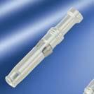
267 heavy mate Information Drawings turned contacts Series Part Number Wire gauge A B Drawing Figure heavy mate D, DD, M 100 Pieces.N X VN C VN C VN C VN C VN C 0,14-0,37 0,5 0,75-1,0 1,5 2,5 0,9 1,1 1,45 1,75 2,25 2,6 2,6 2,6 3,0 3,2 VN C VN C VN C VN C VN C 0,14-0,37 0,5 0,75-1,0 1,5 2,5 0,9 1,1 1,45 1,75 2,25 2,6 2,6 2,6 3,0 3,2.N X heavy mate E, EE 100 Pieces VN C VN C VN C VN C VN C 0,5 0,75-1,0 1,5 2,5 4,0 1,1 1,45 1,75 2,3 2,9 2,6 2,6 3,0 3,2 4,0.N X VN C VN C VN C VN C VN C 0,5 0,75-1,0 1,5 2,5 4,0 1,1 1,45 1,75 2,3 2,9 2,6 2,6 3,0 3,2 4,0.N X heavy mate K 100 Pieces VN C VN C VN C VN C 1,5 2,5 4 6 heavy mate M 100 Pieces VN C VN C VN C VN C VN C 0,5 0,75-1,0 1,5 2,5 4,0 1,1 1,45 1,75 2,25 2,85 2,6 2,6 3,0 3,45 3,9.N XX VN C VN C VN C VN C VN C 0,5 0,75-1,0 1,5 2,5 4,0 1,1 1,45 1,75 2,25 2,85 2,6 2,6 3,0 3,45 3,9.N XX VN C VN C VN C VN C VN C 1,5 2,5 4,0 6,0 10,0 1,75 2,25 2,85 3,55 4,4 3,0 3,45 3,9 4,9 5,9.N X VN C VN C VN C VN C VN C 1,5 2,5 4,0 6,0 10,0 1,75 2,25 2,85 3,55 4,4 3,0 3,45 3,9 4,9 5,9.N X 267


268 heavy mate Information Drawings FO, coax contacts Series Part Number Drawing single contact Figure heavy mate M, FO N N heavy mate M, Coax 17 DM DM DM DM
Han PCB termination. Han-Fast Lock PCB adapter for Han DD PCB adapter for Han DDD module
 Han termination Contents Page Han-Fast Lock... 20.11 adapter for Han DD... 20.13 adapter for Han DDD module... 20.16 adapter for Han 40 A Axial module... 20.18 adapter for Han E... 20.20 adapter for Han
Applications
 Han PCB adapter Contents Page Technical characteristics PCB adapter for Han DD... 20.02 Han DD Inserts with PCB adapter... 20.03 Technical characteristics PCB adapter for Han E... 20.04 Han E Inserts with
Han-Brid. Contents Han-Brid Features Han-Brid Data interfaces Han-Brid Overview Han-Brid Cu
 Contents Page Features... 19.02 Data interfaces... 19.03 Overview... 19.04 Cu... 19.06 F.O.... 19.08 Quintax 3 A... 19.10 RJ45 C... 19.12 USB / FireWire... 19.14 Han 4 A SC... 19.16 Hoods/Housings... 19.18
Technical data: Pin Spacing
 282 Female Connectors, Double-Row Pin Spacing: 3.5 mm Universal connection for all conductor types Unique, compact, double-row connector system for conductor cross sections up to 1.5 mm 2 High-density,
Details of the Han-Terminal block connector Han D AV Han D AV Distributor Han E AV Han ES AV
 Contents -Terminal Block Connectors Page Details of the -Terminal block connector........................ 08.02 D................................................... 08.10 D Distributor...........................................
Han R 23. Circular Connector. Certified acc. to DIN EN ISO 9001 in design/ development, production, installation and servicing.
 Circular Connector Certified acc to DIN EN ISO 9001 in design/ development, production, installation and servicing Data Sheet 0039-4 Circular Connectors Features Size R 23 Outer diameter 26 mm High contact
Data sheet. HDC insert HDC HQ 7 FC
 The HQ series - big features in a compact design The electrical values speak for themselves. The standard HE crimp contacts can also be used here. The wire connection level is designed as a crimp contact
VMEbus systems System description Technical characteristics System description
 Directory chapter 06 / inverse Page VMEbus systems................................................ 06.02 System description.............................................. 06.03 Technical characteristics..........................................
Extract from new. Device Connectivity catalogue. HARTING har-flex. People Power Partnership
 Extract from new Device Connectivity catalogue HARTING har-flex People Power Partnership . har-flex CONNECTORS The continuous scalability by an even number of contacts, i.e. from 6 to 100, of the HARTING
Data sheet. HDC insert HDC HQ 5 FC
 A small unit that packs a big punch. The electrical values speak for themselves. Proven HE crimp contacts can also be used here. Number of poles: 5 (+PE) Rated current: 16 A Rated voltage: 250 V Rated
ERNIPRESS Trapezoidal-Connectors Series TMC
 ERNIPRESS Trapezoidal-Connectors Series TMC Subminiatur-D Connectors to DIN 41 652/IEC 807-3 with Press-fit zone General Solderless press-in technology for connectors in bus systems permits rationalized
ODU MAC LC. Modular Attachable Connector System
 Catalogue No. 1004 LC-a ODU MAC LC Modular Attachable Connector System ODU Steckverbindungssysteme GmbH & Co. KG, Pregelstr. 11, 84453 Mühldorf a. Inn, Germany Phone: +49/ 86 31/61 56-0, Fax: +49/ 86 31/61
M23 Connectors and cables
 Contents Product Description: SAI M23 Connectors.2 Contact assignment.7 Technical data.8 Overview.10 M23 connector for signal transmission.12 M23 connector for power transmission.18 Moulded M23 cables.22
09. DIN Connectors
 . Connectors Connectors that comply with have been in use for years for both board-to-board applications and cable-to-board applications. Their robustness and universality are legendary. The classic signal
Description of parts Panel mounting Insert mounting without/with Carrier element Plastic housings
 - Contents Page Features -... 11.02 Component range -... 11.03 Description of parts... 11.04 Latching parts without/with Strain relief and Panel mounting parts... 11.06 Panel mounting... 11.08 Insert mounting
2.54 mm Single Row Connector (SRC) MaxiBridge.
 MaxiBridge.") 2.54 mm Single Row Connector (SRC) www.erni.com Katalog Catalog D E 074593 074518 Ausgabe 02/10 3, 03/05 www.erni.com Edition 7 1 www.erni.com Catalog E 074593 02/10 Edition 7 Table of Contents General...2
2.54 mm Single Row Connector (SRC) www.erni.com Katalog Catalog D E 074593 074518 Ausgabe 02/10 3, 03/05 www.erni.com Edition 7 1 www.erni.com Catalog E 074593 02/10 Edition 7 Table of Contents General...2
Modular Connector System with High Power, Signal, Fibre-Optic, Coaxial Contacts and Pneumatic Valves
 Modular Connector System with High Power, Signal, Fibre-Optic, Coaxial Contacts and Pneumatic Valves 2 rue René Laennec 51500 Taissy France Fax: 03 26 85 19 08, Tel : 03 26 82 49 29 E-mail:hvssystem@hvssystem.com
2.54 mm Single Row Connector (SRC) MaxiBridge.
 MaxiBridge.") 2.54 mm Single Row Connector (SRC) www.erni.com Katalog Catalog D E 074591 074518 02/10 Ausgabe 3, 03/05 Edition www.erni.com 7 1 www.erni.com Catalog E 074591 02/10 Edition 7 Table of Contents General..............................................................................................2
2.54 mm Single Row Connector (SRC) www.erni.com Katalog Catalog D E 074591 074518 02/10 Ausgabe 3, 03/05 Edition www.erni.com 7 1 www.erni.com Catalog E 074591 02/10 Edition 7 Table of Contents General..............................................................................................2
07. har-link Interface Connectors
 . Interface Connectors The highest data rates in combination with perfect shielding characterize the connector. This way data can be passed on optimally within the control cabinet. The locking mechanism
revos revos Industrial Multipole Connectors
 revos revos Industrial Multipole Connectors Catalog 2018 revos MINI Plant II, Rodezstraße in Bamberg Company headquarters in Bamberg STOCKO main plant in Wuppertal Solutions for Building technology AT
07. har-link INTERFACE CONNECTORS
 . INTERFACE CONNECTORS The highest data rates in combination with perfect shielding characterize the connector. This way data can be passed on optimally within the control cabinet. The locking mechanism
Ø 36 Ø 34 Ø 3,5 Ø 3,5
 HEC English version locking system, 8 and contacts Degree of protection IP68/IP69K Crimp termination Diameter 6 mm VDE-, UL-approval Designed for harsh environments Description Male cable connector Drawing
Data sheet... OMNIMATE Power - series BL/SL 7.62HP BLZ 7.62HP/04/180LR SN BK BX
 Power on board #96 100% safety, 100% integration, 100% cost-effectiveness: The compact and efficient solution for UL-600V applications in the lower performance range (up to 12 kva). 29 A at 400V (IEC)
1-Conductor Female Connector with Levers Pin Spacing: mm MCS MAXI 16
 -Conductor Female Connector with evers Pin Spacing: 0.6 mm MCS MAXI 6 Intuitive and tool-free lever actuation Universal connection for all conductor types Push-in termination of solid or ferruled conductors
Amphenol Amphenol-Tuchel Electronics GmbH. heavy mate. Heavy Duty Connectors Core Programme.
 Amphenol Amphenol-Tuchel Electronics GmbH heavy mate Heavy Duty Connectors Core Programme www.industrial-amphenol.com heavy mate is a Modular Metal Connector Line Modular system With the new series heavy
Powermate Range pitch 10.16
 Contents owermate Range pitch.16 owermate Range pitch.16 owermate Range pitch.16 Male connectors with solder connection.2 Socket connectors with clamping yoke connection.8.1 owermate Range pitch.16 SU.16/9
ODU MINI-SNAP PC Product Description. ODU MINI-SNAP PC: The Connector with Push-Pull-Locking in Plastic
 ODU MINI-SNAP PC Product Description ODU MINI-SNAP PC: The Connector with Push-Pull-Locking in Plastic Cylindrical Connectors are generally available with several locking mechanisms: The most frequently
Connectors DIN 41612/IEC
 Connectors DIN 41612/IEC 60603-2 and completions ERNI-electronic components quality assessed according to CECC 75101-801 2 www.erni.com/contact/ General information The DIN 41612/IEC 60603-2 connector
400 Series Buccaneer BUCCANEER FOR POWER. IP68 rating tested at 1.054kg/sq cm (15lb/sq in) 10m depth for 2 weeks
 10m depth for 2 weeks") IP68 rating tested at 1.054kg/sq cm (15lb/sq in) m depth for 2 weeks IP69K, Tested in accordance with DIN 40050/Part 9 IP6k9k 2 and 3 pole -, 250V rating 4, 6 and 8 pole -, 125V rating and 12 pole -, 50V
IP68 rating tested at 1.054kg/sq cm (15lb/sq in) m depth for 2 weeks IP69K, Tested in accordance with DIN 40050/Part 9 IP6k9k 2 and 3 pole -, 250V rating 4, 6 and 8 pole -, 125V rating and 12 pole -, 50V
UTS UTS. UTS provides a connection that performs faster, easier, safer and more reliable, it makes :
 Company Profile UTS Contents Company profile... 2 Contents... 3 Description... 3 Overview TRIM TRIO... 4 Major features & benefits 5-9 Contact styles... 5 Rapid and secure locking system... 6 Rapid and
D-Sub SEaled subminiature D connectors, 2.54 mm pitch
 SE D-Sub SEaled subminiature D connectors, 2.54 mm pitch Page Technical characteristics.......................................... 02 IP 67 versions with turned solder cups......... 04 IP 67 versions with
High-density multi-pin connectors
 High-density multi-pin connectors Mating and mounting conditions to DIN 41612/IEC 60603-2 General With the ever increasing miniaturization and higher packaging densities in highly integrated circuits there
AT, ATM and ATP Series Kits Are Now Available!!!
 Sine Systems AT, ATM and ATP Series Kits Are Now Available!!! Q: Why are we offering kits? A: Making kits available to our customers allows for reducing the number of part numbers necessary for any given
Operating voltages up to 40 kvdc Operating current up to 30 Amps Advanced contact technology Silver plated and gold plated contacts available High
 Operating voltages up to 40 kvdc Operating current up to 30 Amps Advanced contact technology Silver plated and contacts available High performance insulation material General characteristics and technical
Connectors DIN 41612/IEC
 Connectors DIN 41612/IEC 60603-2 and completions General information The DIN 41612/IEC 60603-2 connector family consists of 13 basic sizes and many complementary versions. It was developed for use in 19"
HARTING Connectors for High Mating Cycles
 HARTING Connectors for High Mating Cycles HARTING worldwide Transforming customer wishes into concrete solutions The HARTING Technology Group is skilled in the fields of electrical, electronic and optical
Transforming customer wishes into concrete solutions
 HARTING News 2013 HARTING worldwide Introduction Transforming customer wishes into concrete solutions The HARTING Technology Group is skilled in the fields of electrical, electronic and optical connection,
ERNIPRESS. DIN 41612/IEC Press-fit connectors catalog E /02 Edition 4
 ERNIPRESS DIN 41612/IEC 60603-2 Press-fit connectors 132 www.erni.com/contact/ Benefits of ERNIPRESS Gas-tight, corrosionproof and mechanically strong connection No soldering errors No terminal stress
2.54mm Board to Cable Connectors Series LPV IEC Catalog E /05 Edition 1
 2.54mm Board to Cable Connectors Series LPV IEC 60603-13 www.erni.com Catalog E 074546 05/05 Edition 1 www.erni.com Catalog E 074546 05/05 Edition 1 Table Of Contents Board to Cable Connectors Series LPV.....................................................................2
IDC Assembly (depends on cable) -55/125 C. IDC Assembly (depends on cable) By ambient temperature: 20 C 1,2 A 70 C 0,9 A 100 C 0,6 A
 -55/125 C. IDC Assembly (depends on cable) By ambient temperature: 20 C 1,2 A 70 C 0,9 A 100 C 0,6 A") mm Connectors Surface Mount Technology, Solderless Pressfit, IDC Electrical And Mechanical Characteristics Number of Pins Technical data Climate Category Bearing and operating temperature area Current
mm Connectors Surface Mount Technology, Solderless Pressfit, IDC Electrical And Mechanical Characteristics Number of Pins Technical data Climate Category Bearing and operating temperature area Current
ODU DOCK and ODU ROB. Connectors for Docking and Robot Systems.
 and ODU ROB Connectors for Docking and Robot Systems Robust Circular Connectors and ROB Applications Industrial robots Tool change and depot systems Cable connections for robot systems Test equipment Features
Data sheet. OMNIMATE Signal - series B2L/S2L row S2L-SMT 3.50/08/180G 3.5SN BK BX
 OMNIMATE Signal - series /S2L 3.50-2-row High-temperature-resistant, straight, 2-tier male connector for all common soldering methods. Optimised for automatic assembly. Packed in box or tape. 3.2 mm solder
Industrial Ethernet Panel-Mount Adaptors for PROFINET or EtherNet/IP Applications
 Industrial Ethernet Panel-Mount Adaptors for PROFINET or EtherNet/IP Applications Type 0981 ENC 100 RJ45/M12 adaptor, female receptacle connector M12, D coding, chassis side thread PG 9, RJ45 female connector,
Better all-round. DataVoice Circular connectors STX M12x1 IP67 Connector series for industrial applications. PoE+ 10 GBE. coded.
 Better all-round. X coded D coded 10 GBE PoE+ DataVoice Circular connectors STX M12x1 IP67 Connector series for industrial applications STX M12x1 IP67 connector series With the STX M12x1 IP67 connector
AX SERIES XLR CABLE CONNECTORS
 AX SERIES XLR CABLE CONNECTORS The revolutionary AX series of XLR connectors introduce an exciting contemporary look and feel to the professional audio interconnect market. They are designed to complement
Standard Buccaneer BUCCANEER FOR POWER
 IP8 rating tested at 1.05kg/sq cm (15lb/sq in) 10m depth for weeks and.8kg/sq cm (10lb/sq in) 100m depth for hours IPK, Tested in accordance with DIN 0050/Part IPkk Water and dustproof to IP8 when mated,,,,,,
SBE 80 / SBO 60 Connectors - up to 80 Amps
 Connectors - up to 80 Amps SBE and SBO connectors build on the capability of the two pole SB connectors by offering up to 8 auxiliary power / signal contacts along with an IEC 60950 touch safe housing.
Surface Mount Terminal Blocks with Push-Buttons
 Surface Mount Terminal Blocks with Push-Buttons Surface Mount Terminal Blocks with Push-Buttons Pin Spacing 4 mm, 8 mm 2060 Series Surface mount terminal blocks with CAGE CLAMP S connection and push-buttons
Item No.: /
 mounting adapter also for DIN 35 rail; % protected against mismating; Plate thickness 06x12 mm; Male connector; with snap-in mounting foot; 4-pole; pin spacing 35 mm / 0138 in; with 209-137 mounting adapter
Multipole Industrial Connectors Heavy duty connectors
 Multipole Industrial Connectors Heavy duty connectors Compact catalogue For more technical details, specifications ions and special products please consult the Westec General Catalogue Multipole Industrial
Module 18plus. Description. 18plus
 Module 8plus Description Wiring of load and signal lines in a space-saving manner will become ever more important for designers of electrical plants and systems, because all control cabinets and control
07. har-link Interface Connectors
 . Interface Connectors The highest data rates in combination with perfect shielding characterize the connector. This way data can be passed on optimally within the control cabinet. The locking mechanism
High-density multi-pin connectors
 High-density multi-pin connectors Mating and mounting conditions to DIN 41612/IEC 60603-2 General With the ever increasing miniaturization and higher packaging densities in highly integrated circuits there
modlink msdd Front panel interfaces
 Tight and with full visibility The connecting mechanism of the Modlink MSDD with integrated locking mechanism allows the components to be used under protection class IP65. This protection class prevents
EPIC LS1 Series Circular Power & Mixed Power Connectors
 EPIC LS1 Series Circular Power & Mixed Power Connectors EPIC LS1 Circular and Mixed Power Connectors are designed to DIN specification EN61984 and have a standard M23 threaded connection housing. They
Right angle press-fit D-Sub connectors
 Right angle press-fit D-Sub connectors Version in Standard and in Eurostyle General The new generation of right angle D-Sub connectors with press-fit termination of the TMC series are according to DIN
2.54 mm Single Row Connector (SRC) MaxiBridge.
 MaxiBridge.") 2.54 mm Single Row Connector (SRC) www.erni.com Katalog Catalog D E 074593 074518 10/08 Ausgabe 3, 03/05 Edition www.erni.com 4 1 www.erni.com Catalog E 074593 10/08 Edition 4 Table of Contents General..............................................................................................2
2.54 mm Single Row Connector (SRC) www.erni.com Katalog Catalog D E 074593 074518 10/08 Ausgabe 3, 03/05 Edition www.erni.com 4 1 www.erni.com Catalog E 074593 10/08 Edition 4 Table of Contents General..............................................................................................2
Connector System for Fluorescent Lighting Fixtures. Connectors for In-Line Mounting of Fluorescent Lighting Fixtures. Fully Polarized Connectors
 Connector System for Fluorescent Lighting Fixtures Connectors for In-Line Mounting of Fluorescent Lighting Fixtures Fully Polarized Connectors Luminaire Disconnect Connectors Pluggable Lighting Connectors
02. PushPull CONNECTORS
 . CONNECTORS A distributed automation system does not contain any central automated control cabinets. Controls, sensors and actuators are designed for a high degree of protection (IP 65 / IP 67) and are
AMPHENOL AUSTRALIA WEBSITE. AMPHENOL WORLD HEADQUARTERS WEBSITE ISO VIEW OF AC3MM ISO VIEW OF AC3FI
 ISO VIEW OF AC3MM ISO VIEW OF AC3FI AMPHENOL AUSTRALIA WEBSITE AMPHENOL WORLD HEADQUARTERS WEBSITE www.amphenol.com 2 AC SERIES XLR CABLE CONNECTORS Amphenol Australia have been manufacturing and designing
Hypermod Series. Heavy Duty Modular Connectors. Technical Characteristics
 Heavy Duty Modular Connectors Heavy duty modular rectangular connector for signal, power, fiber optics, databus and coaxial contacts. From 1 mm to 3.5 mm nominal pin DIA crimp contacts; 3, 5, 10 and 20
TABLE OF CONTENTS. IEC and IEC Pin and Sleeve Devices. IEC and IEC Mechanical Interlocks. Manual Disconnect Switches
 TABLE OF CONTENTS IEC-309-1 and IEC-309- Pin and Sleeve Devices Introduction... - Material Specifications... 6-7 North American Ratings (0 to 100 Amp)... 8-16 Accessories... 17-18 International Ratings
CMC Hybrid Connectors Standard and Power Versions
 The Molex family of provides a sealed, high-density, modular and cost-effective connection system for heavy-duty, powertrain and body-electronics applications in the transportation industry The CMC connector
CMC CP Terminals CP 0.635mm (.025 ) CP 1.50mm (.059 ) CP 2.80mm (.110 ) FEATURES AND SPECIFICATIONS
 CP 1.50mm (.059 ) CP 2.80mm (.110 ) FEATURES AND SPECIFICATIONS") FEATURES AND SPECIFICATIONS CMC Connectors sealed, high-density, modular and cost-effective connection system for heavy-duty applications The CMC connector family from Molex is a sealed, high-density connection
FEATURES AND SPECIFICATIONS CMC Connectors sealed, high-density, modular and cost-effective connection system for heavy-duty applications The CMC connector family from Molex is a sealed, high-density connection
Connect - Contact - Control. Connectors according to UIC VE EP Series. F 121.en
 Connect - Contact - Control Connectors according to UIC 541-5 VE 123 F 121.en 2 Connector to UIC standard 541-5 VE, The connector is designed in accordance with the specifications of the international
HARTING News 2007
 98 42 914 0201 HARTING News 2007 People Power Partnership Quality Connections Worldwide HARTING was founded in 1945 by the family that still owns the company. Its headquarters are situated in Espelkamp,
Male connector; 6-pole; pin spacing 3.5 mm / in; 100% protected against mismating
 Male connector; 6-pole; pin spacing 35 mm / 0138 in; % protected against mismating Item Male connector; 6-pole; pin spacing 35 mm / 0138 in; % protected against mismating Marking Business data Supplier
4000 Series Buccaneer
 Sealed to IP66 IP68 and IP69K when mated IP68 rating tested at 1.054kg/sq cm (15lb/sq in) m depth for 2 weeks 2, 3,, & 12 pole configuration Power ratings up to 13A, 600V Cable range from 3 to 7mm Diameter
Standard Series Standard
 Standard Series Standard Technical Data Coupler connector, cable connector and coupler connector rectangular housing Locking screw connection Protection IP 50 to IP 54 with conexil in the housing, flat-gasket
SL 7.62/8/90B3.2SN OR - Weidmüller
 1624430000 7.62/8/90B3.2SN - Weidmüller Page 1 of 6 Searching... This page in English Product catalogue Product selector Configurator Your opinion Terms Your inquiry list contains 0 articles Product catalogue
- 1 - General ordering data Order No
 General ordering data Order No. 1727690000 Part designation B2L 3.5/16 SN SW Version EAN 4032248037889 Qty. 50 pc(s). PCB plug-in connector, Female connectors, Tension clamp connection, Clamping range,
02. PushPull CONNECTORS
 . CONNECTORS A distributed automation system does not contain any central automated control cabinets. Controls, sensors and actuators are designed for a high degree of protection (IP 65 / IP 67) and are
EPIC Circular Connectors CIRCON M23 Series
 The M3 connectors have many inherent features which offer application advantages and provide significant benefits for the customer. These features make it one of the most application friendly connectors
Accessories Cassette Style Mating Connectors
 Description All 19" cassette style converters are equipped with either H11, H15, H15S4, or H15S2 male connectors. Mating female connectors are available as accessories. The four H- type connector versions
Magnetic and Hydraulic-Magnetic Circuit Breaker 8340-F...
 Magnetic and Hydraulic-Magnetic Circuit Breaker 830-F... Description Single and multipole magnetic circuit breakers with trip-free mechanism and toggle actuation. A choice of fast magnetic only or hydraulically
Magnetic and Hydraulic-Magnetic Circuit Breaker 8340-F...
 Description Single and multipole magnetic circuit breakers with trip-free mechanism and toggle actuation. A choice of fast magnetic only or hydraulically delayed switching characteristics (S-type MO or
AC SERIES XLR CABLE CONNECTORS
 AC SERIES XLR CABLE CONNECTORS Amphenol Australia have been manufacturing and designing innovative XLR connectors since 1955 and were the first to offer the cost saving Insulation Displacement Contact
- 1 - General ordering data Order No
 General ordering data Order No. 1627280000 Part designation SLS 5.08/6B SN OR Version EAN 4008190199791 Qty. 50 pc(s). PCB plug-in connector, Male connectors, Clamping yoke connection, Clamping range,
CROWN LINE Power Bus Bar Distribution System
 COWN LINE Power Bus Bar Distribution System COWN LINE Power Bus Bar Distribution System The pluggable bus bar system Currents up to 300 Amps Up to 2 meters in length Pluggable breakers VDE finger proof
Switch cabinet housings. Distribution housings. Appropriate housings for each application. Our experience. Your safety.
 Switch cabinet housings Distribution housings Appropriate housings for each application Our experience. Your safety. Overview of the housing ranges Mounting rail bus system In-Rail Bus...6 Switch cabinet
Technical Data, 4-way High Voltage. Cannon APD / ISO Connectors. Electrical Data. Mechanical Data. Materials List
 Technical Data, 4-way High Voltage APD 4-way connectors are the original DIN72585 (now ISO 15170) versions using a 2,5 mm contact system. Designed for automotive applications they also meet the requirements
 Distributed by: www.jameco.com 1-800-831-4242 The content and copyrights of the attached material are the property of its owner. Power Connectors FEATURES AND SPECIFICATIONS Features and Benefits Positive
8WH5 Combination Plug-In Terminals
 8WH Combination Plug-In Terminals /2 Introduction / 8WH through-type terminals 1) /7 8WH hybrid through-type terminals with ipo connection /8 8WH9 plugs 1) 1) Also available as a PE version More technical
The reliable connector to power up your device
 The reliable connector to power up your device The UTL series is a sealed plastic connector range able to carry up to 16A 277V. Key shape coupling with latching retention system Designed to be overmoulded
Ø 11,4 21,5. M9 x 0,5 Ø 12 Ø 11,4. M9 x 0,5 Ø 12. M9 x 0,5
 Subminiature 7 series Screw termination M9 8 contacts Degree of protection IP7 Solder termination Moulded versions Diameter, mm Male angled connector 8,, Ø,, Contacts Cable outlet Ordering-No. 99 00 70
Accessories Cassette Style Mating Connectors
 Description All 19" cassette style converters are equipped with either H11-, H15-, H15S4, or H15S2 male connectors. Mating female connectors are available as accessories. The four H- type connector versions
INTERCONNECT SOLUTIONS
 INTERCONNECT SOLUTIONS Products Overview Connect with Us... Experience Makes the Difference Who We Are We have been designing and manufacturing interconnect products for over 40 years. Today we supply
Sales: Technical: Fax:
 DATA SHEET Weatherproof Order code Manufacturer code Description 23-2650 PX0410/02S/5560 2 WAY FREE SOCKET MICRO BUCCANNEER 23-2652 PX0410/03S/5560 3 WAY FREE SOCKET MICRO BUCCANNEER (RC) 23-2654 PX0410/04S/4550
Electrical Components Catalog Universal MATE-N-LOK Connector System
 Introduction Product Facts Pins and sockets can be intermixed in the same housing Positive polarization Rear cavity identification Contacts completely enclosed in housings Positive locking housings Insulation
M12 Field Wireable Connectors. M12 CAT.6A Field Wireable Connectors. M12 Field Wireable Connectors for PROFINET
 M12 Connectors Application Advantage Shielded design ETHERLINE Ethernet Cable, Connectors & Tools M12 Field Wireable Connectors Male Female Temperature Range: Max. 85 C Nominal Voltage: Nominal Current:
Datasheet. Datasheet-No Type: RS(W)T(S) - RK(W)T(S) -.../ M. Page: 1 of 7
T(S) - RK(W)T(S) -.../ M. Page: 1 of 7") The information/details in this datasheet merely contain general descriptions or performance factors which, when applied in an actual situation, do not always correspond with the described form, and may
The information/details in this datasheet merely contain general descriptions or performance factors which, when applied in an actual situation, do not always correspond with the described form, and may
Summary of shell housings and accessories Shell housing A Shell housing D EMC housing
 Directory chapter 20 Page Summary of shell and accessories........................... 20.02 housing C.......................... 20.04 housing A................................................. 20.08 housing
SEPTEMBER C.CS.1000 / GB
 SEPTEMBER 2005 - C.CS.1000 / GB C R I M P F L E X C O N N E C T O R S CRIMPFLEX connectors TECHNICAL DATA MATERIAL Phosphor bronze MALE SOLDER TAB PLATING The standard connector is tin plated (thickness
DUBOX SHUNTS BOARD/WIRE-TO-BOARD CONNECTORS FEATURES & BENEFITS. Dual-beam contacts for added reliability
 BOARD/WIRE-TO-BOARD CONNECTORS DUBOX SHUNTS FEATURES & BENEFITS Dual-beam contacts for added reliability Slotted cutout in low profile housing simplifies electrical testing Side-by-side and end-to-end
Magnetic and Hydraulic-Magnetic Circuit Breaker 8340-T...
 Description ngle, two and three pole magnetic and hydraulic-magnetic circuit breakers with trip-free mechanism and toggle actuation. A choice of fast magnetic only hydraulically delayed switching characteristics
HARTING. Interface Connectors. People Power Partnership
 11 5 HARTING Interface Connectors People Power Partnership Directory chapter 00 Modular metric high speed connectors, 2.0 mm pitch Page connector system general information......................... 00.04
Amphenol. Printed Circuit Board Technology NAFI + UHD CONNECTORS STANDARD. RELIABLE. PROVEN.
 Amphenol Printed Circuit Board Technology NAFI + UHD CONNECTORS STANDARD. RELIABLE. PROVEN. FEATURES & BENEFITS Available in 2 through 4 rows - Offers maximum design flexibility Tested and qualified to
Introduction. The information pages provide standard data common to all D-subminiature connectors. These include:
 Connectors Information Introduction The D-subminiature is one of the most popular styles of connectors in the I/O category. It is used in computer, telecom, datacom, medical, and test instrumentation applications
Modular plugs, accessories and tooling
 Modular plugs, accessories and tooling Introducing the new Cat 6A/6 modular plugs, slim-line boots and color clips CommScope modular plug portfolio CommScope offers a vast portfolio of Modular Plugs for
ATP SERIES ATP Series
 ATP SERIES ATP Series 87 ATP Series Overview ATP Series connectors are designed as a high-performance, cost-effective, thermoplastic solution to be used within the Marine, Heavy Equipment, Agricultural,